EP4095444A1 - Air-processing apparatus - Google Patents
Air-processing apparatus Download PDFInfo
- Publication number
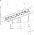
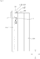
- EP4095444A1 EP4095444A1 EP22173423.9A EP22173423A EP4095444A1 EP 4095444 A1 EP4095444 A1 EP 4095444A1 EP 22173423 A EP22173423 A EP 22173423A EP 4095444 A1 EP4095444 A1 EP 4095444A1
- Authority
- EP
- European Patent Office
- Prior art keywords
- louver
- air
- disposed
- rotation shaft
- processing apparatus
- Prior art date
- Legal status (The legal status is an assumption and is not a legal conclusion. Google has not performed a legal analysis and makes no representation as to the accuracy of the status listed.)
- Granted
Links
Images














Classifications
-
- F—MECHANICAL ENGINEERING; LIGHTING; HEATING; WEAPONS; BLASTING
- F24—HEATING; RANGES; VENTILATING
- F24F—AIR-CONDITIONING; AIR-HUMIDIFICATION; VENTILATION; USE OF AIR CURRENTS FOR SCREENING
- F24F13/00—Details common to, or for air-conditioning, air-humidification, ventilation or use of air currents for screening
- F24F13/08—Air-flow control members, e.g. louvres, grilles, flaps or guide plates
- F24F13/10—Air-flow control members, e.g. louvres, grilles, flaps or guide plates movable, e.g. dampers
- F24F13/14—Air-flow control members, e.g. louvres, grilles, flaps or guide plates movable, e.g. dampers built up of tilting members, e.g. louvre
- F24F13/15—Air-flow control members, e.g. louvres, grilles, flaps or guide plates movable, e.g. dampers built up of tilting members, e.g. louvre with parallel simultaneously tiltable lamellae
-
- F—MECHANICAL ENGINEERING; LIGHTING; HEATING; WEAPONS; BLASTING
- F24—HEATING; RANGES; VENTILATING
- F24F—AIR-CONDITIONING; AIR-HUMIDIFICATION; VENTILATION; USE OF AIR CURRENTS FOR SCREENING
- F24F13/00—Details common to, or for air-conditioning, air-humidification, ventilation or use of air currents for screening
- F24F13/08—Air-flow control members, e.g. louvres, grilles, flaps or guide plates
- F24F13/10—Air-flow control members, e.g. louvres, grilles, flaps or guide plates movable, e.g. dampers
- F24F13/14—Air-flow control members, e.g. louvres, grilles, flaps or guide plates movable, e.g. dampers built up of tilting members, e.g. louvre
- F24F13/1426—Air-flow control members, e.g. louvres, grilles, flaps or guide plates movable, e.g. dampers built up of tilting members, e.g. louvre characterised by actuating means
-
- F—MECHANICAL ENGINEERING; LIGHTING; HEATING; WEAPONS; BLASTING
- F24—HEATING; RANGES; VENTILATING
- F24F—AIR-CONDITIONING; AIR-HUMIDIFICATION; VENTILATION; USE OF AIR CURRENTS FOR SCREENING
- F24F1/00—Room units for air-conditioning, e.g. separate or self-contained units or units receiving primary air from a central station
- F24F1/0007—Indoor units, e.g. fan coil units
- F24F1/0011—Indoor units, e.g. fan coil units characterised by air outlets
-
- F—MECHANICAL ENGINEERING; LIGHTING; HEATING; WEAPONS; BLASTING
- F24—HEATING; RANGES; VENTILATING
- F24F—AIR-CONDITIONING; AIR-HUMIDIFICATION; VENTILATION; USE OF AIR CURRENTS FOR SCREENING
- F24F13/00—Details common to, or for air-conditioning, air-humidification, ventilation or use of air currents for screening
- F24F13/02—Ducting arrangements
- F24F13/06—Outlets for directing or distributing air into rooms or spaces, e.g. ceiling air diffuser
-
- F—MECHANICAL ENGINEERING; LIGHTING; HEATING; WEAPONS; BLASTING
- F24—HEATING; RANGES; VENTILATING
- F24F—AIR-CONDITIONING; AIR-HUMIDIFICATION; VENTILATION; USE OF AIR CURRENTS FOR SCREENING
- F24F13/00—Details common to, or for air-conditioning, air-humidification, ventilation or use of air currents for screening
- F24F13/08—Air-flow control members, e.g. louvres, grilles, flaps or guide plates
- F24F13/10—Air-flow control members, e.g. louvres, grilles, flaps or guide plates movable, e.g. dampers
- F24F13/14—Air-flow control members, e.g. louvres, grilles, flaps or guide plates movable, e.g. dampers built up of tilting members, e.g. louvre
-
- F—MECHANICAL ENGINEERING; LIGHTING; HEATING; WEAPONS; BLASTING
- F24—HEATING; RANGES; VENTILATING
- F24F—AIR-CONDITIONING; AIR-HUMIDIFICATION; VENTILATION; USE OF AIR CURRENTS FOR SCREENING
- F24F13/00—Details common to, or for air-conditioning, air-humidification, ventilation or use of air currents for screening
- F24F13/28—Arrangement or mounting of filters
-
- F—MECHANICAL ENGINEERING; LIGHTING; HEATING; WEAPONS; BLASTING
- F24—HEATING; RANGES; VENTILATING
- F24F—AIR-CONDITIONING; AIR-HUMIDIFICATION; VENTILATION; USE OF AIR CURRENTS FOR SCREENING
- F24F8/00—Treatment, e.g. purification, of air supplied to human living or working spaces otherwise than by heating, cooling, humidifying or drying
- F24F8/10—Treatment, e.g. purification, of air supplied to human living or working spaces otherwise than by heating, cooling, humidifying or drying by separation, e.g. by filtering
- F24F8/108—Treatment, e.g. purification, of air supplied to human living or working spaces otherwise than by heating, cooling, humidifying or drying by separation, e.g. by filtering using dry filter elements
-
- F—MECHANICAL ENGINEERING; LIGHTING; HEATING; WEAPONS; BLASTING
- F24—HEATING; RANGES; VENTILATING
- F24F—AIR-CONDITIONING; AIR-HUMIDIFICATION; VENTILATION; USE OF AIR CURRENTS FOR SCREENING
- F24F13/00—Details common to, or for air-conditioning, air-humidification, ventilation or use of air currents for screening
- F24F13/08—Air-flow control members, e.g. louvres, grilles, flaps or guide plates
- F24F13/10—Air-flow control members, e.g. louvres, grilles, flaps or guide plates movable, e.g. dampers
- F24F13/14—Air-flow control members, e.g. louvres, grilles, flaps or guide plates movable, e.g. dampers built up of tilting members, e.g. louvre
- F24F13/1426—Air-flow control members, e.g. louvres, grilles, flaps or guide plates movable, e.g. dampers built up of tilting members, e.g. louvre characterised by actuating means
- F24F2013/1433—Air-flow control members, e.g. louvres, grilles, flaps or guide plates movable, e.g. dampers built up of tilting members, e.g. louvre characterised by actuating means with electric motors
-
- F—MECHANICAL ENGINEERING; LIGHTING; HEATING; WEAPONS; BLASTING
- F24—HEATING; RANGES; VENTILATING
- F24F—AIR-CONDITIONING; AIR-HUMIDIFICATION; VENTILATION; USE OF AIR CURRENTS FOR SCREENING
- F24F13/00—Details common to, or for air-conditioning, air-humidification, ventilation or use of air currents for screening
- F24F13/08—Air-flow control members, e.g. louvres, grilles, flaps or guide plates
- F24F13/10—Air-flow control members, e.g. louvres, grilles, flaps or guide plates movable, e.g. dampers
- F24F13/14—Air-flow control members, e.g. louvres, grilles, flaps or guide plates movable, e.g. dampers built up of tilting members, e.g. louvre
- F24F13/1426—Air-flow control members, e.g. louvres, grilles, flaps or guide plates movable, e.g. dampers built up of tilting members, e.g. louvre characterised by actuating means
- F24F2013/1446—Air-flow control members, e.g. louvres, grilles, flaps or guide plates movable, e.g. dampers built up of tilting members, e.g. louvre characterised by actuating means with gearings
Definitions
- the present disclosure relates to an air-processing apparatus, and more particularly to an air-processing apparatus including a louver for adjusting the direction of air blown out through an outlet.
- An air-processing apparatus may conceptually include an air conditioner for adjusting indoor temperature and an air purifier for removing fine dust from indoor air.
- a stand-type indoor unit, a wall-mounted indoor unit, or a ceiling-mounted indoor unit may be mounted in an indoor space in order to adjust the temperature of the indoor space.
- An air purifier is generally configured to be movable, and is disposed on the floor of an indoor space in order to purify contaminated air in the indoor space.
- the region in which the air conditioner discharges heat-exchanged air and the region in which the air purifier discharges purified air may differ from each other.
- a filter may be disposed in the inlet region of the air conditioner.
- HEPA high-efficiency particulate air
- Korean Patent Laid-Open Publication No. 10-2012-0034446 discloses a structure in which a separate air conditioner is disposed in a lower space in a stand-type air conditioner. This structure enables individual air conditioning for a lower region and an upper region in an indoor space. However, it is difficult to perform air conditioning and air purification for overlapping regions.
- a ceiling-mounted air-processing apparatus or a wall-mounted air-processing apparatus has an outlet formed to be long in a leftward-rightward direction.
- this type of air-processing apparatus includes a louver for adjusting the direction of air blown out from the outlet formed in the leftward-rightward direction and a louver actuator for changing the orientation of the louver.
- Korean Patent Laid-Open Publication No. 10-2018-0066546 discloses an air-processing apparatus capable of adjusting the direction of air that is blown out by changing the orientation of a vane.
- a driving motor for changing the orientation of the vane is disposed on the left or right side of the vane, and thus an outlet may not be formed in the portion in which the driving motor is disposed, which may incur a problem in which the area of the outlet is comparatively reduced.
- a louver which is formed to be long in the leftward-rightward direction, may be relatively susceptible to distortion. It is still another object of the present disclosure to provide an air-processing apparatus including a louver having a stable structure.
- an air-processing apparatus may include a case having an outlet formed therein, a louver rotatably disposed in the case and configured to adjust the direction of air flowing through the outlet, and a louver actuator configured to adjust the orientation of the louver.
- the louver may include a louver rotation shaft and a plurality of vanes disposed so as to be spaced apart from each other in a radial direction based on the louver rotation shaft.
- the louver actuator may be disposed so as to be in contact with the vane located at the outermost position among the plurality of vanes to change the orientation of the louver. Accordingly, the size of the outlet may be secured in a leftward-rightward direction to the maximum extent.
- the louver rotation shaft may extend along the rotation center of the louver.
- the plurality of vanes may include an outer vane spaced outwards apart from the louver rotation shaft in the radial direction and a plurality of inner vanes disposed between the louver rotation shaft and the outer vane so as to be spaced apart from each other in the radial direction.
- the louver may be connected at the outer circumferential surface of the outer vane to the louver actuator.
- the louver actuator may be disposed outside the louver in the radial direction of the louver rotation shaft.
- a vane gear may be formed on the outer circumferential surface of the outer vane in a circumferential direction, and the louver actuator may be engaged with the vane gear to rotate the louver.
- the louver actuator may be disposed outside the louver in the radial direction of the louver rotation shaft.
- the outer vane may have an arc shape that extends in the circumferential direction based on the louver rotation shaft. Accordingly, it is possible to change the orientation of the louver and to change the direction of air that is discharged.
- the plurality of inner vanes may be shorter than the outer vane. That is, the outer vane may be formed to be larger than the inner vanes in order to change the orientation of the louver and to adjust the direction of air.
- Each of the plurality of inner vanes may have a different length from the remaining ones of the plurality of inner vanes.
- the lengths of the plurality of inner vanes may gradually increase in a direction approaching the louver rotation shaft. That is, the lengths of the plurality of inner vanes may gradually decrease in a direction approaching the outer vane. Accordingly, it is possible to prevent a reduction in the size of a flow path between the outer vane and the inner vanes.
- the spacing distance between the outer vane and each of the plurality of inner vanes may gradually increase from above to below.
- Each of the plurality of inner vanes may include a lower inner vane portion formed to be inclined so as to be gradually closer to the louver rotation shaft in a downward direction and an upper inner vane portion formed to be bent and extend upwards from the upper end of the lower inner vane portion. This structure is determined in consideration of the direction in which the lower inner vane portion for guiding air that is discharged is oriented according to a change in the orientation of the louver.
- the louver may include an axial vane extending from the louver rotation shaft, and the axial vane may extend in a direction parallel to the lower inner vane portion. Accordingly, it is possible to effectively guide the direction of air that flows along the louver rotation shaft.
- the louver may include a pair of end panels disposed at both ends of the plurality of vanes in a direction perpendicular to the plurality of vanes and a support panel disposed between the pair of end panels and provided at one side thereof with a vane gear.
- the vane gear may be engaged with the louver actuator. Accordingly, the plurality of vanes may be stably disposed.
- the louver actuator may be spaced apart from the louver rotation shaft in a centrifugal direction, and may be disposed so as to be in contact with the outer circumferential surface of the louver. That is, the louver actuator for rotating the louver may not be disposed on the side surface of the louver, and thus the size of the louver may increase to the left and right surfaces of the outlet.
- the louver actuator may include a louver gear configured to be engaged with one side of the louver to rotate the louver and a louver motor configured to rotate the louver gear.
- the louver actuator may include a pair of louver gears arranged so as to be spaced apart from each other and engaged with one side of the louver to rotate the louver, a gear rotation shaft interconnecting the pair of louver gears, and a louver motor connected to the gear rotation shaft to rotate the gear rotation shaft. Accordingly, it is possible to easily rotate the louver, which is formed to be long in the leftward-rightward direction.
- the case may include an upper cover, a lower cover disposed below the upper cover, a rear cover forming an inlet and supporting the filter device mounted thereto, and a front cover disposed so as to be spaced forwards apart from the rear cover.
- the louver may be rotatably disposed at the lower end of the front cover. Accordingly, it is possible to discharge air in the downward direction or the forward direction of the case.
- the front cover may include a louver protrusion having formed therein a louver groove in which the louver rotation shaft is disposed in order to limit a range within which the louver rotates.
- the louver protrusion may include an upper protruding portion forming a surface that is inclined from the upper end of the louver groove in a rearward-upward direction and a lower protruding portion forming a surface that is inclined from the lower end of the louver groove in a forward-downward direction. Accordingly, it is possible to limit the rotation of the louver in both directions.
- FIGS. 1 to 35C indicate an upward direction, a downward direction, a leftward direction, a rightward direction, a forward direction, and a rearward direction, respectively.
- the aforementioned directions are used only for convenience of description, and are not intended to limit the scope of the disclosure. Thus, the aforementioned directions may be set differently according to some reference.
- An air-conditioning system of the present disclosure includes a first air-processing apparatus 100, which adjusts the temperature of air through heat exchange between the air and a refrigerant, and a second air-processing apparatus 200, which is disposed on one side of the first air-processing apparatus in order to remove foreign substances from the air.
- the air-conditioning system of the present disclosure includes a plurality of air-processing apparatuses 100a, 100b, and 200.
- the air-conditioning system of the present disclosure includes one or two or more first air-processing apparatuses 100a and 100b and one or two or more second air-processing apparatuses 200.
- the air-conditioning system of the present disclosure may include a filter cleaner 300, which moves along the surface in which inlets 102a and 202a of the plurality of air-processing apparatuses 100a, 100b, and 200 are formed in order to clean pre-filters 188 and 288 disposed in the inlets 102a and 202a.
- the air-conditioning system of the present disclosure includes one second air-processing apparatus 200 and two first air-processing apparatuses 100 disposed on both sides of the second air-processing apparatus 200.
- this is merely illustrative, and the numbers and arrangement of first and second air-processing apparatuses 100 and 200 may be set differently.
- the air-conditioning system includes a guide rail 10, which is disposed at the rear sides of the first air-processing apparatuses 100 and the second air-processing apparatus 200 in order to guide movement of the filter cleaner 300.
- Support rails 116 and 244 for supporting the movement of the filter cleaner 300 may be disposed at the upper ends of the rear surfaces of the first air-processing apparatuses 100 and the second air-processing apparatus 200.
- the support rails may include first support rails 116 disposed at the first air-processing apparatuses 100 and a second support rail 244 disposed at the second air-processing apparatus 200.
- the first support rails 116 may be formed integrally with first rear covers 114 (refer to FIG. 8 ) of the first air-processing apparatuses 100, which will be described later.
- the second support rail 244 may be formed integrally with a second rear cover 242 (refer to FIG. 24 ) of the second air-processing apparatus 200, which will be described later.
- the guide rail 10 is disposed on the rear sides of the first rear covers 114 and the second rear cover 242.
- the guide rail 10 is disposed above the first inlets 102a and the second inlet 202a.
- the guide rail 10 has a structure that extends in the leftward-rightward direction on the rear sides of the first rear covers 114 and the second rear cover 242.
- the guide rail 10 may be fixedly disposed below first rail-fixing protrusions 117 of the first rear covers 114 and a second rail-fixing protrusion 245 of the second rear cover 242.
- the guide rail 10 includes a gear rail 20, which has threads to be engaged with a moving gear (not shown) of the filter cleaner 300, and a roller rail 22, which is in contact with a guide roller (not shown) of the filter cleaner 300.
- the roller rail 22 is disposed behind the gear rail 20.
- the roller rail 22 is disposed at each of the upper side and the lower side of the guide rail 10.
- the gear rail 20 is disposed in front of the roller rail 22.
- the gear rail 20 is formed on the lower surface of the guide rail 10.
- the gear rail 20 may have the shape of a rack gear.
- the guide rail 10 When viewed from the rear, the guide rail 10 may have a structure in which the gear rail 20 is shielded by the roller rail 22.
- a rail groove 24 is formed in the rear surface of the guide rail 10.
- the rail groove 24 has a shape that is recessed in the forward direction and extends in the leftward-rightward direction.
- An object to be sensed 26 is disposed in the rail groove 24.
- the object to be sensed 26 may be provided in a plural number, and the plurality of objects to be sensed may be disposed so as to be spaced apart from each other in the leftward-rightward direction.
- a sensor (not shown) may be disposed at the filter cleaner 300, and when the sensor senses the object to be sensed 26, the position of the filter cleaner 300 may be detected.
- the object to be sensed 26 may be formed in a structure corresponding to the sensor.
- the object to be sensed 26 may have the shape of a protrusion that protrudes rearwards.
- the sensor is a Hall sensor
- the object to be sensed 26 may be implemented as a magnet.
- An end plate 28 for limiting movement of the filter cleaner 300 in one direction is disposed at the left end or the right end of the guide rail 10.
- the end plate 28 is disposed in a direction perpendicular to the direction in which the guide rail 10 extends.
- the end plate 28 protrudes rearwards from the rear cover 114.
- the end plate 28 is provided with a charging terminal 30, with which a connection terminal 320 of the filter cleaner 300 is brought into contact.
- the charging terminal 30 protrudes from the end plate 28 in the direction in which the guide rail 10 extends. Accordingly, when the filter cleaner 300 reaches the end plate 28, the connection terminal 320 of the filter cleaner 300 may be brought into contact with and connected to the charging terminal 30.
- the first air-processing apparatus 100 induces air to exchange heat with a refrigerant and discharges the heat-exchanged air to the outside.
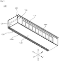
- the first air-processing apparatus 100 has a first inlet 102a formed in one side thereof in order to suction air thereinto and a first outlet 102b formed in another side thereof perpendicular to the first inlet 102a in order to discharge air therefrom.
- the first inlet 102a is formed so as to be perpendicular to the surface of the floor or ceiling.
- the first outlet 102b is formed so as to be open downwards.
- the first outlet 102b is formed perpendicular to the first inlet 102a.
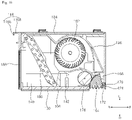
- the first air-processing apparatus 100 includes a first fan 182, which causes air to flow, a first fan motor 184, which rotates the first fan 182, and a heat exchanger 186, through which a refrigerant flows to exchange heat with air.
- the first air-processing apparatus 100 includes a first case 102, which forms the external appearance of the first air-processing apparatus 100, and a first housing 132, which is disposed inside the first case 102 and which forms a flow path through which air flows.
- the first air-processing apparatus 100 includes a first louver 150, which is rotatably disposed in the first case 102 in order to adjust the direction of air that is discharged from the first outlet 102b, and a first louver actuator 174, which changes the orientation of the first louver 150.
- the first air-processing apparatus 100 may include a first control box 190 for controlling the operation of the first fan motor 184 or the operation of the first louver actuator 174.
- the first case 102 includes a first upper cover 104, which is secured to the ceiling, a first lower cover 106, which is disposed below the first upper cover 104, a first rear cover 114, which forms therein the first inlet 102a and to which a first pre-filter 188 is mounted, a first front cover 118, which is disposed so as to be spaced forwards apart from the first rear cover 114, and two first side covers 128, which are disposed at both side ends of the first lower cover 106.
- the first case 102 further includes a first bottom cover 130, which is disposed below the first lower cover 106.
- the first inlet 102a is formed in the first rear cover 114.
- the guide rail 10 may be mounted on the outer surface of the first rear cover 114.
- the first inlet 102a is formed in the lower portion of the first rear cover 114.
- the first pre-filter 188 is mounted in the first inlet 102a formed in the first rear cover 114.
- the guide rail 10 and the first support rail 116 for guiding movement of the filter cleaner 300 are mounted on the first rear cover 114.
- the guide rail 10 is disposed above the first inlet 102a.
- the first support rail 116 is disposed at the upper end of the first rear cover 114.
- the guide rail 10 may be provided separately from the first rear cover 114.
- the first support rail 116 may be formed integrally with the first rear cover 114.
- the first support rail 116 includes a first top plate 116a, which protrudes rearwards from the upper end of the first rear cover 114, and a first bent portion 116b, which is bent and extends downwards from the rear end of the first top plate 116a.
- a top roller 326 (refer to FIG. 2 ) of the filter cleaner 300 may be in contact with the first bent portion 116b.
- the first rear cover 114 is disposed behind a first vertical plate 110 of the first lower cover 106, which will be described later.
- the first rear cover 114 is fixedly disposed behind the first vertical plate 110.
- the first upper cover 104 has a first fixing recess 104a formed in the upper surface thereof, into which a fixing member 12 for fixing the first case 102 to the ceiling is inserted.
- a plurality of first fixing recesses 104a is formed in the upper surface of the first upper cover 104.
- the fixing member 12 is inserted into and fixed to each of the plurality of first fixing recesses 104a.
- the fixing member 12 may have a substantial "[" shape when viewed from the side.
- the fixing member 12 may be connected to a mounting member 14 that is fixed to the ceiling, thereby fixing the first case 102 to the ceiling.
- the first upper cover 104 may include two side plates 105, which are bent and extend downwards from both side ends thereof. Each of the two side plates 105 may be connected to a respective one of the two first side covers 128.
- the first lower cover 106 is disposed below the first housing 132.
- the first louver actuator 174 is disposed on the first lower cover 106.
- the first lower cover 106 includes a first horizontal plate 108, which is disposed above the first bottom cover 130, a first vertical plate 110, which is disposed at the rear side of the first horizontal plate 108 so as to be perpendicular thereto and in which a first inner suction hole 110a is formed, and two first side walls 112, which are bent and extend upwards from both side ends of the first horizontal plate 108.
- the first louver actuator 174 is disposed on the first horizontal plate 108.
- the first horizontal plate 108 has a connection slit 108a formed therein to allow a vertical protrusion 131 of the first bottom cover 130 to be inserted thereinto.
- each of the two first side covers 128 is connected at the lower portion thereof to the first lower cover 106, and is connected at the upper portion thereof to the first upper cover 104.
- a first rotation support rod 168 for supporting rotation of the first louver 150 is disposed on each of the two first side covers 128.
- the first rotation support rod 168 is connected to each of both ends of the first louver 150, thereby supporting rotation of the first louver 150.
- the first front cover 118 is disposed in front of the first housing 132. Referring to FIG. 9 , the lower end of the first front cover 118 is spaced a predetermined gap apart from the front end portion 106a of the first lower cover 106.
- the first outlet 102b is formed between the first front cover 118 and the first lower cover 106.
- a first louver protrusion 120 in which a first louver groove 122 for receiving a louver rotation shaft 160 is formed, is formed on the first front cover 118 in order to limit the range within which the first louver 150 can rotate.
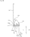
- the first louver protrusion 120 is formed to be long in the leftward-rightward direction, in which the first front cover 118 is formed. Referring to FIG. 14B , the first louver protrusion 120 has the first louver groove 122 formed therein to allow the louver rotation shaft 160 of the first louver 150 to be disposed therein. The first louver groove 122 is also formed to be long in the leftward-rightward direction, in which the first louver protrusion 120 extends.
- a first support-rod recess 124 in which a first auxiliary support rod 170 is disposed is formed between the left end and the right end of the first louver protrusion 120.
- the first auxiliary support rod 170 may be fixedly disposed on the first front cover 118, and may support rotation of the first louver 150.
- the first auxiliary support rod 170 is disposed between the two first rotation support rods 168, which will be described later.
- the first auxiliary support rod 170 may be connected to the first louver 150 via a first auxiliary rotation shaft 172.
- the first louver protrusion 120 includes an upper protruding portion 120a, which forms a surface that is inclined from the upper end of the first louver groove 122 in the rearward-upward direction, and a lower protruding portion 120b, which forms a surface that is inclined from the lower end of the first louver groove 122 in the forward-downward direction.
- a first stepped portion 126 which interferes with an end portion of a first upper housing 134 to be described later, is formed in the first front cover 118.
- the first housing 132 is disposed inside the first case 102, and forms therein a space through which air flows.
- the first fan 182 and the heat exchanger 186 are disposed inside the first housing 132.
- the heat exchanger 186 is disposed in a region adjacent to the first inlet 102a.
- the heat exchanger 186 is disposed so as to be inclined toward the first fan 182 to thereby increase a heat-exchange area and minimize resistance to air flow.
- the first fan motor 184 for rotating the first fan 182 is disposed inside the first housing 132.
- the first fan motor 184 is disposed on the rotation shaft of the first fan 182 in order to rotate the first fan 182.
- the first fan 182 may be implemented as a cross-flow fan, which is configured to suction air into one side thereof in the radial direction and to discharge air from another side thereof in the radial direction.
- a fan support bracket 146 may be disposed inside the first housing 132 in order to support rotation of the first fan 182 or to support placement of the first fan motor 184.
- the first housing 132 includes a first upper housing 134, which is disposed above the first fan 182, and a first lower housing 138, which is disposed below the first fan 182.
- the first upper housing 134 and the first lower housing 138 form discharge guides 136 and 144, along which air flows from the first fan 182 to the first outlet 102b.
- the first upper housing 134 may be mounted to the first upper cover 104.
- the lower end of the first upper housing 134 may be disposed on the upper side of the first stepped portion 126 of the first front cover 118.
- the first upper housing 134 includes an upper guide 136, along which air flowing out of the first fan 182 moves to the first outlet 102b.
- the upper guide 136 induces air flowing along the first fan 182 to move downwards.
- the upper guide 136 induces air flowing out of the first fan 182 to move toward the first front cover 118.
- the first lower housing 138 is disposed above the first lower cover 106.
- the first lower housing 138 includes a drain pan 140, which is disposed below the heat exchanger 186 in order to collect therein condensation dropping from the heat exchanger 186.
- the drain pan 140 is disposed below the heat exchanger 186 in the region in which the heat exchanger 186 is disposed.
- the first lower housing 138 includes a driving device cover 142, which is disposed in front of the drain pan 140 and which protrudes upwards from the first lower cover 106.
- the driving device cover 142 forms a space thereunder in which to dispose the first louver actuator 174.
- the driving device cover 142 protrudes at an incline further upwards from the region in which the drain pan 140 is disposed to the region in which the first fan 182 is disposed.
- the driving device cover 142 may induce air passing through the heat exchanger 186 to flow to the region in which the first fan 182 is disposed.
- the driving device cover 142 includes a lower guide 144 for inducing air passing through the first fan 182 to flow to the first outlet 102b.
- the lower guide 144 is spaced apart from the upper guide 136 so as to form a discharge flow path 132a.
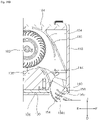
- the lower guide 144 has a first gear hole 142a formed in the portion thereof corresponding to the region in which the first louver gear 176 of the first louver actuator 174 is disposed. Referring to FIG. 9 , a portion of the first louver gear 176 may protrude outside the first gear hole 142a and may be in contact with the first louver 150.
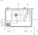
- the first air-processing apparatus 100 includes a first louver 150, which is rotatably disposed in the first outlet 102b in order to adjust the direction of air blown out through the first outlet 102b, and a first louver actuator 174 for adjusting the orientation of the first louver 150.
- the first louver 150 includes a plurality of vanes 154, 156, and 158, which are spaced apart from each other in the radial direction based on the rotation shaft.
- the first louver 150 includes a louver rotation shaft 160, which extends along the rotation center of the first louver 150, an outer vane 154, which is spaced outwards apart from the louver rotation shaft 160 in the radial direction, a plurality of inner vanes 156, which are spaced apart from each other in the radial direction between the louver rotation shaft 160 and the outer vane 154, and a vane gear 166, which is formed on the outer surface of the outer vane 154 in the circumferential direction.
- the plurality of vanes 154, 156, and 158 may include the outer vane 154 and the plurality of inner vanes 156.
- the louver rotation shaft 160 may be disposed so as to be in contact with the first front cover 118.
- the louver rotation shaft 160 is disposed in the first louver groove 122 in the first front cover 118.
- the orientation of the plurality of vanes 154, 156, and 158, which are spaced apart from each other in the radial direction based on the louver rotation shaft 160, may be changed.
- the louver rotation shaft 160 may include an axial vane 158, which extends from the louver rotation shaft 160 in a direction parallel to the inner vanes 156.
- the axial vane 158 extends in a direction parallel to the lower portions of the inner vanes 156.
- the outer vane 154 is disposed farther from the louver rotation shaft 160 than the inner vanes 156.
- the outer vane 154 may be longer than the inner vanes 156 in the circumferential direction.
- the outer vane 154 is formed in the circumferential direction based on the louver rotation shaft 160.
- the inner vanes 156 are disposed between the louver rotation shaft 160 and the outer vane 154 so as to be spaced apart from each other.
- the inner vanes 156 are shorter than the outer vane 154.
- the inner vanes 156 are longer than the axial vane 158.
- the inner vanes 156 have different lengths, respectively.
- the lengths of the inner vanes 156 gradually increase in a direction approaching the louver rotation shaft 160.
- the lengths of the inner vanes 156 gradually decrease in a direction approaching the outer vane 154.
- the inner vanes 156 include lower inner vane portions 156a1, 156b1, and 156c1, which are inclined so as to be gradually closer to the louver rotation shaft 160 in a downward direction, and upper inner vane portions 156a2, 156b2, and 156c2, which are bent and extend upwards from the upper ends of the lower inner vane portions 156a1, 156b1, and 156c1.
- the axial vane 158 extends in a direction parallel to the lower inner vane portions 156a1, 156b1, and 156c1.
- the inner vanes 156 include a first inner vane 156a, which is disposed closest to the louver rotation shaft 160, a second inner vane 156b, which is disposed farther from the louver rotation shaft 160 than the first inner vane 156a, and a third inner vane 156c, which is disposed farther from the louver rotation shaft 160 than the second inner vane 156b.
- the first louver 150 includes end panels 162, which are disposed at both ends of the vanes 154, 156, and 158 in a direction perpendicular to the vanes 154, 156, and 158, and a support panel 164, which is disposed between the end panels 162.
- the vane gear 166 is disposed on one side of the support panel 164.
- the end panels 162, which are disposed at both ends of the vanes 154, 156, and 158, may prevent the air flowing through the first louver 150 from being discharged in the leftward-rightward direction.
- the support panel 164 which is disposed between the end panels 162, may support the vanes 154, 156, and 158.
- the vanes 154, 156, and 158 are formed to be long in the longitudinal direction, in which the louver rotation shaft 160 is formed. Accordingly, the support panel 164 may stably maintain the arrangement of the vanes 154, 156, and 158.
- the support panel 164 may be formed in a fan shape.
- the vane gear 166 is disposed on the outer circumferential end of the support panel 164.
- the vane gear 166 may form threads on the outer circumferential end of the support panel 164 in the circumferential direction.
- the support panel 164 may be connected to the first auxiliary support rod 170.
- the support panel 164 forms a space in which the first auxiliary support rod 170 is disposed in the portion in which the louver rotation shaft 160 is formed.
- the first auxiliary rotation shaft 172 is disposed inside the first auxiliary support rod 170, and the first auxiliary support rod 170 is connected to the louver rotation shaft 160 via the first auxiliary rotation shaft 172.
- the vanes 154, 156, and 158 are disposed so as to protrude downwards further than the end panels 162 and the support panel 164.
- the first louver actuator 174 is spaced apart from the louver rotation shaft 160 of the first louver 150 in the centrifugal direction.
- the first louver actuator 174 is spaced apart from the louver rotation shaft 160, and is disposed so as to be in contact with the outer circumferential surface of the first louver 150.
- the first louver actuator 174 includes a first louver gear 176, which is in contact with the first louver 150 in order to rotate the first louver 150, and a first louver motor 178 for rotating the first louver gear 176.
- two first louver gears 176 are provided so as to be spaced apart from each other, and the first louver actuator 174 further includes a first gear rotation shaft 180 interconnecting the two first louver gears 176.
- the two first louver gears 176 which are connected to each other via the first gear rotation shaft 180, may rotate in the same direction.
- the first louver 150 may be switched to a first mode P1 for forming an oblique air current in the forward direction, a second mode P2 for forming a horizontal air current in the forward direction, and a third mode P3 for forming a vertical air current toward the floor.
- the first louver 150 is disposed above the first bottom cover 130 in the first mode P1.
- the lower end of each of the vanes 154, 156, and 158 of the first louver 150 may be disposed above the first bottom cover 130 in the vertical direction.
- the lower end of the outer vane 154 may be oriented in a direction perpendicular to the floor.
- the lower end of each of the inner vanes 156a, 156b, and 156c may be inclined in the forward direction.
- a portion of the first louver 150 is disposed below the first bottom cover 130 in the second mode P2.
- the lower end of the outer vane 154 and the lower end of each of the inner vanes 156a, 156b, and 156c may be disposed below the first bottom cover 130 in the vertical direction.
- the inclination angle ⁇ 2 formed by the lower inner vane portion 157a of each of the inner vanes 156a, 156b, and 156c and the floor may be set to 30 degrees or less. Accordingly, in the second mode P2, the air flowing through the first louver 150 may be discharged in a direction substantially parallel to the floor.
- the first louver 150 is disposed above the first bottom cover 130 in the third mode P3.
- the lower end of the outer vane 154 and the lower end of each of the inner vanes 156a, 156b, and 156c may be disposed above the first bottom cover 130 in the vertical direction.
- the inclination angle ⁇ 3 formed by the lower inner vane portion 157a of each of the inner vanes 156a, 156b, and 156c and the floor may be set to a range from 60 degrees to 90 degrees. Accordingly, in the third mode P3, the air flowing through the first louver 150 may be discharged in a direction substantially perpendicular to the floor.
- the second air-processing apparatus 200 induces air to flow through a filter device 284 and discharges the air to the outside.
- the second air-processing apparatus 200 has a second inlet 202a formed in one side thereof in order to suction air thereinto and a second outlet 202b formed in another side thereof perpendicular to the second inlet 202a in order to discharge air therefrom.
- the second inlet 202a is formed so as to be perpendicular to the surface of the floor or ceiling.
- the second outlet 202b is formed so as to be open downwards.
- the second outlet 202b is formed perpendicular to the second inlet 202a.
- the second air-processing apparatus 200 includes a second fan 280, which causes air to flow, and a second fan motor 280a, which rotates the second fan 280.
- a plurality of second fans 280 is provided, and a plurality of second fan motors 280a is provided such that each of the second fan motors 280a is connected to a respective one of the second fans 280.
- the second air-processing apparatus 200 includes a second case 202, which forms the external appearance of the second air-processing apparatus 200, and a second housing 268, which is disposed inside the second case 202 and which forms a flow path through which air flows.
- the second air-processing apparatus 200 includes a second louver 290, which is rotatably disposed in the second case 202 in order to adjust the direction of air that is discharged from the second outlet 202b, and a second louver actuator 294, which changes the orientation of the second louver 290.
- the second louver 290 and the second louver actuator 294 disposed in the second air-processing apparatus 200 may have the same structures and perform the same functions as the first louver 150 and the first louver actuator 174 of the first air-processing apparatus 100 described above with reference to FIGS. 12 to 17 . Therefore, the description of the first louver 150 and the first louver actuator 174 of the first air-processing apparatus 100 may apply to the second louver 290 and the second louver actuator 294 disposed in the second air-processing apparatus 200.
- the second air-processing apparatus 200 may include a second control box 290 for controlling the operation of the second fan motor 280a or the operation of the second louver actuator 294.
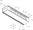
- the second case 202 includes a second upper cover 204, which is secured to the ceiling, a second lower cover 206, which is disposed below the second upper cover 204, a second rear cover 242, which forms therein the second inlet 202a and to which the filter device 284 is mounted, a second front cover 246, which is disposed so as to be spaced forwards apart from the second rear cover 242, and two second side covers 256, which are disposed at both side ends of the second lower cover 206.
- the second case 202 further includes a second bottom cover 258, which is disposed below the second lower cover 206 so as to be movable in the forward-rearward direction.
- the second inlet 202a is formed in the second rear cover 242.
- the guide rail 10 (refer to FIG. 3 ) may be mounted on the outer surface of the second rear cover 242.
- the second inlet 202a, in which the filter device 284 is mounted, is formed in the lower portion of the second rear cover 242.
- the guide rail 10 and the second support rail 244 for guiding movement of the filter cleaner 300 are mounted on the second rear cover 242.
- the guide rail 10 is disposed above the second inlet 202a.
- the second support rail 244 is disposed at the upper end of the second rear cover 242.
- the second support rail 244 includes a second top plate 244a, which protrudes rearwards from the upper end of the second rear cover 242, and a second bent portion 244b, which is bent and extends downwards from the rear end of the second top plate 244a.
- the top roller 326 of the filter cleaner 300 may be in contact with the second bent portion 244b.
- the second rear cover 242 is disposed behind a second vertical plate 214 of the second lower cover 206, which will be described later.
- the second rear cover 242 is fixedly disposed behind the second vertical plate 214.
- a filter-mounting part 234 (refer to FIG. 31 ) for moving the filter device 284 in the upward-downward direction is disposed in the second inlet 202a in the second rear cover 242.
- the filter-mounting part 234 may be moved in the upward-downward direction by a filter-driving device 228, which will be described later.
- the second upper cover 204 has a second fixing recess 204a formed in the upper surface thereof, into which a fixing member 12 for fixing the second case 202 to the ceiling is inserted.
- the second fixing recess 204a formed in the second upper cover 204 may have the same shape as the first fixing recess 104a formed in the first upper cover 104. Accordingly, the second upper cover 204 may be fixed to the mounting member 14 mounted to the ceiling by the fixing member 12 disposed at the upper side of the first upper cover 104.
- the second upper cover 204 may include two side plates 266d, which are bent and extend downwards from both side ends thereof. Each of the two side plates 266d may be connected to a respective one of the two second side covers 256.
- the second lower cover 206 is disposed below the second housing 268.
- the second louver actuator 294 is disposed on the second lower cover 206.
- a cover-driving device 220 for moving the second bottom cover 258 in the forward-rearward direction is disposed on the second lower cover 206.
- the filter-driving device 228 for moving the filter device 284 and the filter-mounting part 234 in the upward-downward direction is disposed on the second lower cover 206.
- the second lower cover 206 includes a second horizontal plate 208, which is disposed above the second bottom cover 258, a second vertical plate 214, which is disposed at the rear side of the second horizontal plate 208 so as to be perpendicular thereto and in which a second inner suction hole 214a is formed, and two second side walls 216, which are bent and extend upwards from both side ends of the second horizontal plate 208.
- the second louver actuator 294 is disposed on the second horizontal plate 208.
- the cover-driving device 220 is disposed above the second horizontal plate 208.
- the second horizontal plate 208 has guide grooves 208a formed therein to allow cover guides 262 and 264 of the second bottom cover 258 to be inserted thereinto.
- the cover-driving device 220 includes a cover-driving gear 222, which meshes with a guide gear 262c of the first cover guide 262, which will be described later, so as to rotate together therewith, and a cover-driving motor 224 for rotating the cover-driving gear 222.
- two cover-driving gears 222 may be provided so as to be spaced apart from each other in the leftward-rightward direction.
- the cover-driving device 220 includes a cover-driving shaft 226 for interconnecting the two cover-driving gears 222 spaced apart from each other. Accordingly, the two cover-driving gears 222 connected to both ends of the cover-driving shaft 226 may rotate identically.
- the second horizontal plate 208 is provided with fixing guides 210, which are connected to the cover guides 262 and 264 of the second bottom cover 258 in order to prevent the second bottom cover 258 from moving in the upward-downward direction.
- the fixing guides 210 protrude upwards from the second horizontal plate 208, and extend in the forward-rearward direction.
- the fixing guides 210 may be disposed so as to be in contact with the first cover guide 262 or the second cover guide 264, which will be described later.
- the fixing guides 210 support the movement of the second bottom cover 258 in the forward-rearward direction.
- the fixing guides 210 prevent the second bottom cover 258 from moving in the upward-downward direction.
- the fixing guides 210 may have fixing protrusions 212, which protrude toward the cover guides 262 and 264.
- the fixing protrusions 212 extend in the forward-rearward direction.
- the fixing protrusions 212 may be disposed so as to be in contact with a first guide protrusion 262b of the first cover guide 262 or a second guide protrusion 264b of the second cover guide 264.
- the fixing protrusions 212 have a structure corresponding to the first guide protrusion 262b of the first cover guide 262 or the second guide protrusion 264b of the second cover guide 264, thereby preventing the second bottom cover 258 from moving in the upward-downward direction.
- the second vertical plate 214 has a second inner suction hole 214a formed therein.
- the second inner suction hole 214a may be formed to have a size corresponding to the second inlet 202a.
- the filter-driving device 228 is disposed on the second vertical plate 214.
- Each of the two second side covers 256 is connected at the lower portion thereof to the second lower cover 206, and is connected at the upper portion thereof to the second upper cover 204.
- a second rotation support rod 292 for supporting rotation of the second louver 290 is disposed on each of the two second side covers 256.
- the second rotation support rod 292, which is connected to each of the second side covers 256, may have the same shape as the first rotation support rod 168 connected to each of the first side covers 128.
- the second front cover 246 is disposed in front of the second housing 268.
- the second front cover 246 may have the same shape as the first front cover 118.
- the second front cover 246 may be disposed in the same manner as the first front cover 118. Therefore, the lower end of the second front cover 246 is spaced a predetermined gap apart from the front end portion of the second lower cover 206, thereby forming the second outlet 202b.
- a second stepped portion 254 which interferes with an end portion of a second upper housing 270 to be described later, is formed in the second front cover 246.
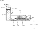
- the second bottom cover 258 is disposed at the second lower cover 206 so as to be movable in the forward-rearward direction. Referring to FIG. 33B , when the second bottom cover 258 is disposed at a rear position adjacent to the second rear cover 242, the second bottom cover 258 may cover the lower side of the filter device 284. Referring to FIG. 34B , when the second bottom cover 258 is disposed at a front position adjacent to the second front cover 246, the second bottom cover 258 may block the second outlet 202b. Referring to FIG. 34B , when the second bottom cover 258 is disposed at a front position adjacent to the second front cover 246, the second bottom cover 258 may open the lower side of the filter device 284.
- the second bottom cover 258 includes a bottom plate 260, which is disposed below the second lower cover 206, and cover guides 262 and 264, which protrude upwards from the bottom plate 260 and which move the bottom plate 260 in the forward-rearward direction.
- the cover guides 262 and 264 include a first cover guide 262, which is connected to the cover-driving device 220 to move the bottom plate 260, and a second cover guide 264, which prevents the bottom plate 260 from vibrating in the upward-downward direction.
- the first cover guide 262 includes a first guide wall 262a, which protrudes upwards from the bottom plate 260 and extends in the forward-rearward direction, a guide gear 262c, which is disposed on one side of the first guide wall 262a and is screwed to the cover-driving device 220, and a first guide protrusion 262b, which is disposed on the opposite side of the first guide wall 262a and guides the movement of the second bottom cover 258 in the forward-rearward direction.
- the second cover guide 264 includes a second guide wall 264a, which protrudes upwards from the bottom plate 260 and extends in the forward-rearward direction, and a second guide protrusion 264b, which is disposed on one side of the second guide wall 264a and guides the movement of the second bottom cover 258 in the forward-rearward direction.
- the second air-processing apparatus 200 includes an inner cover 266, which is disposed above the second lower cover 206 and covers the upper sides of the second louver actuator 294 and the cover-driving device 220.
- the inner cover 266 may guide the flow of air flowing inside the second case 202, and may prevent the air from flowing to the second louver actuator 294.
- the inner cover 266 is coupled to the second lower cover 206 to form a space in which the second louver actuator 294 and the cover-driving device 220 are disposed.
- the inner cover 266 includes an upper plate 266a, which is disposed above the second louver actuator 294, a front plate 266b, which covers the front side of the second louver actuator 294, a rear plate 266c, which covers the rear side of the second louver actuator 294, and side plates 266d, which cover the lateral sides of the second louver actuator 294.
- the rear plate 266c may prevent the air flowing through the filter device 284 from flowing to the space under the inner cover 266.
- the upper plate 266a may guide the air flowing through the filter device 284 to the space in which the second fan 280 is disposed.
- the front plate 266b may guide the air flowing through the second fan 280 toward the second outlet 202b.
- the front plate 266b has a second gear hole 266b 1 formed in the region in which a second louver gear 294a of the second louver actuator 294 is disposed. A portion of the second louver gear 294a may protrude outside the second gear hole 266b 1 (refer to FIG. 25A ), and may be in contact with the second louver 290.
- the inner cover 266 includes a plurality of partition walls 266e, which vertically extend downwards from the upper plate 266a.
- the plurality of partition walls 266e may be spaced apart from each other in the leftward-rightward direction, and may increase the rigidity of the inner cover 266.
- the second housing 268 is disposed inside the second case 202 to form a space in which air flows.
- a second fan 280 and a second fan motor 280a for rotating the second fan 280 are disposed inside the second housing 268.
- the second fan 280 may be implemented as a centrifugal fan, which suctions air in a direction parallel to the rotation axis and discharges air in the centrifugal direction. Accordingly, referring to FIG. 24 , the second fan motor 280a may be disposed inside the second fan 280 to rotate the second fan 280.
- the second fan motor 280a may be fixed to a second upper housing 270, which will be described later.
- the second housing 268 includes a second upper housing 270, which is disposed above the second fan 280, and a second lower housing 274, which is disposed below the second fan 280.
- the second upper housing 270 may be mounted to the second upper cover 204.
- the lower end of the second upper housing 270 may be disposed on the second stepped portion 254 of the second front cover 246.
- the second upper housing 270 includes a front guide 272 for guiding the air flowing through the second fan 280 to the second outlet 202b.
- the front guide 272 extends downwards from the front end of the second upper housing 270.
- the front guide 272 causes the air flowing along the second fan 280 to flow downwards.
- the front guide 272 guides the air flowing through the second fan 280 to the second outlet 202b.
- the front guide 272 is disposed so as to be smoothly connected to the second front cover 246. Accordingly, the air flowing along the front guide 272 flows to the second outlet 202b via the second front cover 246.
- the second fan motor 280a is mounted in the second upper housing 270.
- the second lower housing 274 is disposed above the inner cover 266.
- the second lower housing 274 includes a plurality of fan housings 276 forming spaces in which a plurality of second fans 280 is disposed.
- Each of the fan housings 276 is spaced apart from the outer circumferential surface of the second fan 280 in the radial direction.
- Each of the fan housings 276 has an open front portion. Accordingly, the air flowing in the radial direction of the second fan 280 may be discharged to the open front portion of each of the fan housings 276.
- a fan inlet 276a, through which air is introduced into the second fan 280, is formed below each of the fan housings 276.
- the second lower housing 274 is spaced upwards apart from the inner cover 266. Accordingly, a suction flow path 268a, through which the air passing through the filter device 284 flows, is formed between the second lower housing 274 and the inner cover 266.
- the second lower housing 274 is spaced rearwards apart from the front guide 272 of the second upper housing 270.
- the second lower housing 274 includes a rear guide 278, which is spaced apart from the front guide 272 and extends downwards.
- the second lower housing 274 is spaced upwards apart from the inner cover 266 by the rear guide 278.
- the rear guide 278 forms a second discharge flow path 268b in the upward-downward direction together with the front guide 272.
- the front guide 272 and the rear guide 278 may guide the air flowing from the second fan 180 to the second outlet 202b.
- the filter device 284 is mounted to the filter-mounting part 234.
- the filter-mounting part 234 is movably disposed in the second case 202.
- the filter device 284 and the filter-mounting part 234 may be coupled to each other by means of a first magnet 287 disposed in the filter device 284 and a second magnet 238 disposed in the filter-mounting part 234. Accordingly, the position of the filter device 284 may be changed in the upward-downward direction according to movement of the filter-mounting part 234. Also, a user may easily separate the filter device 284 from the filter-mounting part 234.
- the filter-mounting part 234 includes a mounting body 236, to which the filter device 284 is mounted, and a body gear 240 for adjusting the position of the mounting body 236.
- the mounting body 236 includes an upper body 236a, which is disposed above the filter device 284, side bodies 236b, which extend downwards from both ends of the upper body 236a, a front body 236c, which extends downwards from the front end of the upper body 236a, and a rear body 236d, which extends downwards from the rear end of the upper body 236a.
- the side bodies 236b extend downwards to be longer than the front body 236c or the rear body 236d.
- Two side bodies 236 may be provided at respective ends of the upper body 236a.
- a partition body 236e for isolating a plurality of filter devices 284 from each other may be disposed between the two side bodies 236b.
- the length that the front body 236c extends downwards from the upper body 236a may be longer than the length that the rear body 236d extends downwards from the upper body 236a.
- the front body 236c, the rear body 236d, and the side bodies 236b may guide mounting of the filter device 284 to the filter-mounting part 234.
- a body gear 240 is disposed outside the side body 236b.
- the body gear 240 may be a rack gear in which threads protruding forwards extend in the upward-downward direction.
- a plurality of second magnets 238 is disposed above the upper body 236a.
- the filter device 284 includes a filter case 286, which supports a second pre-filter 288 disposed in one side thereof and has an open opposite side, and a HEPA filter 289, which is disposed so as to be inserted into or withdrawn out of the filter case 286 and functions to remove fine dust.
- the filter case 286 is formed to have a size capable of accommodating the HEPA filter 289.
- the second pre-filter 288 for primarily removing foreign substances from the air introduced into the second inlet 202a is disposed in one side of the filter case 286.
- the filter case 286 has an opening 286a formed in a surface thereof opposite the second pre-filter 288.
- the HEPA filter 289 may be inserted into or withdrawn out of the filter case 286 through the opening 286a.
- the first magnet 287 is disposed on the upper wall of the filter case 286.
- the first magnet 287 is disposed at a position corresponding to the second magnet 238 when the filter device 284 is mounted to the filter-mounting part 234.
- the filter-driving device 228 is disposed on the second lower cover 206, and moves the filter-mounting part 234 in the upward-downward direction.
- the filter-driving device 228 is disposed on the second vertical plate 214.
- the filter-driving device 228 is disposed at each of both side ends of the second vertical plate 214.
- the filter-driving device 228 includes a filter-driving gear 230, which meshes with the body gear 240 and rotates together therewith, and a filter-driving motor 232, which rotates the filter-driving gear 230.
- the filter-driving gear 230 may be implemented as a spur gear.
- the filter-driving gear 230 and the filter-driving motor 232 are fixedly disposed on the second vertical plate 214.
- the second air-processing apparatus 200 includes a second louver 290, which is rotatably disposed in the second outlet 202b in order to adjust the direction of air that is discharged from the second outlet 202b, and a second louver actuator 294, which adjusts the orientation of the second louver 290.
- the second louver 290 and the second louver actuator 294 may have the same structures and perform the same functions as the first louver 150 and the first louver actuator 174 of the first air-processing apparatus 100 described above. Therefore, the description of the first louver 150 and the first louver actuator 174 of the first air-processing apparatus 100 may apply to the second louver 290 and the second louver actuator 294.
- the second bottom cover 258 is disposed below the filter device 284. Accordingly, the lower side of the second louver 270 may be opened, and thus the orientation of the second louver 270 may be changed.
- the filter device 284 and the filter-mounting part 234 for moving the filter device 284 are disposed above the second bottom cover 258.
- the second bottom cover 258 may be moved forwards, and may be disposed below the second outlet 202b.
- the second bottom cover 258 may be moved forwards by the operation of the cover-driving device 220.
- the filter device 284 and the filter-mounting part 234 may be moved downwards.
- the filter-mounting part 234 may be moved downwards by the filter-driving device 228.
- the coupled state of the filter-mounting part 234 and the filter device 284 may be maintained by the first magnet 287 and the second magnet 238. Accordingly, when the filter-mounting part 234 is moved downwards, the filter device 284 is also moved downwards.
- the air-conditioning system of the present disclosure has one or more effects as follows.
- an air-processing apparatus for discharging heat-exchanged air and an air-processing apparatus for discharging purified air are arranged in series in the leftward-rightward direction, it is possible to simultaneously perform air purification and temperature control in an indoor space.
- first air-processing apparatus and the second air-processing apparatus are arranged in the leftward-rightward direction and the louvers disposed in the outlets of the first and second air-processing apparatuses are individually operated, it is possible to individually adjust the directions of air discharged therefrom in consideration of the temperature of air that is discharged, thereby promoting air circulation in an indoor space.
- the louver actuator for driving the louver since the louver actuator for driving the louver is disposed outside in the radial direction of the rotation shaft of the louver, the size of the louver may increase in the leftward-rightward direction. Accordingly, it is possible to secure the size of the outlet in the leftward-rightward direction to the maximum extent. Accordingly, the amount of air that is discharged from the air-processing apparatus may be maximized, and thus the air in the indoor space may be rapidly processed.
- the outer vane has an arc shape and is spaced apart from the louver rotation shaft, the range within which the outer vane can protrude outside the outlet or can move inside the outlet may increase, thereby increasing the angular range within which air is discharged.
- the louver has a structure including a plurality of vanes and a support panel, and is connected to the louver actuator at the support panel. Accordingly, the rigidity of the louver may increase, and thus the orientation of the louver may be stably changed.
- the louver groove which is formed in the case to receive therein the louver rotation shaft, includes an upper protruding portion and a lower protruding portion for limiting the rotation of the louver. Accordingly, the rotation of the louver may be stably limited.
Landscapes
- Engineering & Computer Science (AREA)
- Chemical & Material Sciences (AREA)
- Combustion & Propulsion (AREA)
- Mechanical Engineering (AREA)
- General Engineering & Computer Science (AREA)
- Air-Flow Control Members (AREA)
- Air Filters, Heat-Exchange Apparatuses, And Housings Of Air-Conditioning Units (AREA)
Abstract
Description
- The present disclosure relates to an air-processing apparatus, and more particularly to an air-processing apparatus including a louver for adjusting the direction of air blown out through an outlet.
- An air-processing apparatus may conceptually include an air conditioner for adjusting indoor temperature and an air purifier for removing fine dust from indoor air.
- In the case of an air conditioner, a stand-type indoor unit, a wall-mounted indoor unit, or a ceiling-mounted indoor unit may be mounted in an indoor space in order to adjust the temperature of the indoor space.
- An air purifier is generally configured to be movable, and is disposed on the floor of an indoor space in order to purify contaminated air in the indoor space.
- Because an air conditioner and an air purifier are physically separated from each other and are located at different positions, the region in which the air conditioner discharges heat-exchanged air and the region in which the air purifier discharges purified air may differ from each other.
- In order to address this problem, a filter may be disposed in the inlet region of the air conditioner. However, when a high-efficiency particulate air (HEPA) filter for use in an air purifier is mounted in the air conditioner, the HEPA filter acts as resistance to the flow of air to a heat exchanger. Therefore, it is difficult to use a HEPA filter in an air conditioner.
-
Korean Patent Laid-Open Publication No. 10-2012-0034446 - A ceiling-mounted air-processing apparatus or a wall-mounted air-processing apparatus has an outlet formed to be long in a leftward-rightward direction. In addition, this type of air-processing apparatus includes a louver for adjusting the direction of air blown out from the outlet formed in the leftward-rightward direction and a louver actuator for changing the orientation of the louver.
-
Korean Patent Laid-Open Publication No. 10-2018-0066546 - It is an object of the present disclosure to provide an air-conditioning system capable of simultaneously supplying heat-exchanged air and purified air to an indoor space.
- It is another object of the present disclosure to provide an air-conditioning system capable of rapidly circulating heat-exchanged air and purified air in an indoor space.
- It is still another object of the present disclosure to provide an air-processing apparatus including a louver and a louver actuator capable of opening an outlet, which is formed in the air-processing device in a leftward-rightward direction, to the maximum extent.
- It is still another object of the present disclosure to provide an air-processing apparatus capable of increasing the range within which the direction of air is capable of being adjusted by a louver.
- A louver, which is formed to be long in the leftward-rightward direction, may be relatively susceptible to distortion. It is still another object of the present disclosure to provide an air-processing apparatus including a louver having a stable structure.
- It is still another object of the present disclosure to provide an air-processing apparatus capable of stably restricting movement of a louver.
- The objects of the present disclosure are not limited to the above-described objects, and other objects not mentioned herein may be readily understood by those skilled in the art from the following description.
- The invention is defined in the independent claim. Dependent claims describe preferred embodiments.
- In order to accomplish the above and other objects, an air-processing apparatus according to an embodiment of the present disclosure may include a case having an outlet formed therein, a louver rotatably disposed in the case and configured to adjust the direction of air flowing through the outlet, and a louver actuator configured to adjust the orientation of the louver. The louver may include a louver rotation shaft and a plurality of vanes disposed so as to be spaced apart from each other in a radial direction based on the louver rotation shaft. The louver actuator may be disposed so as to be in contact with the vane located at the outermost position among the plurality of vanes to change the orientation of the louver. Accordingly, the size of the outlet may be secured in a leftward-rightward direction to the maximum extent.
- The louver rotation shaft may extend along the rotation center of the louver. The plurality of vanes may include an outer vane spaced outwards apart from the louver rotation shaft in the radial direction and a plurality of inner vanes disposed between the louver rotation shaft and the outer vane so as to be spaced apart from each other in the radial direction. The louver may be connected at the outer circumferential surface of the outer vane to the louver actuator. The louver actuator may be disposed outside the louver in the radial direction of the louver rotation shaft.
- A vane gear may be formed on the outer circumferential surface of the outer vane in a circumferential direction, and the louver actuator may be engaged with the vane gear to rotate the louver. The louver actuator may be disposed outside the louver in the radial direction of the louver rotation shaft.
- The outer vane may have an arc shape that extends in the circumferential direction based on the louver rotation shaft. Accordingly, it is possible to change the orientation of the louver and to change the direction of air that is discharged.
- The plurality of inner vanes may be shorter than the outer vane. That is, the outer vane may be formed to be larger than the inner vanes in order to change the orientation of the louver and to adjust the direction of air.
- Each of the plurality of inner vanes may have a different length from the remaining ones of the plurality of inner vanes.
- The lengths of the plurality of inner vanes may gradually increase in a direction approaching the louver rotation shaft. That is, the lengths of the plurality of inner vanes may gradually decrease in a direction approaching the outer vane. Accordingly, it is possible to prevent a reduction in the size of a flow path between the outer vane and the inner vanes.
- The spacing distance between the outer vane and each of the plurality of inner vanes may gradually increase from above to below.
- Each of the plurality of inner vanes may include a lower inner vane portion formed to be inclined so as to be gradually closer to the louver rotation shaft in a downward direction and an upper inner vane portion formed to be bent and extend upwards from the upper end of the lower inner vane portion. This structure is determined in consideration of the direction in which the lower inner vane portion for guiding air that is discharged is oriented according to a change in the orientation of the louver.
- The louver may include an axial vane extending from the louver rotation shaft, and the axial vane may extend in a direction parallel to the lower inner vane portion. Accordingly, it is possible to effectively guide the direction of air that flows along the louver rotation shaft.
- The louver may include a pair of end panels disposed at both ends of the plurality of vanes in a direction perpendicular to the plurality of vanes and a support panel disposed between the pair of end panels and provided at one side thereof with a vane gear. The vane gear may be engaged with the louver actuator. Accordingly, the plurality of vanes may be stably disposed.
- The louver actuator may be spaced apart from the louver rotation shaft in a centrifugal direction, and may be disposed so as to be in contact with the outer circumferential surface of the louver. That is, the louver actuator for rotating the louver may not be disposed on the side surface of the louver, and thus the size of the louver may increase to the left and right surfaces of the outlet.
- The louver actuator may include a louver gear configured to be engaged with one side of the louver to rotate the louver and a louver motor configured to rotate the louver gear.
- The louver actuator may include a pair of louver gears arranged so as to be spaced apart from each other and engaged with one side of the louver to rotate the louver, a gear rotation shaft interconnecting the pair of louver gears, and a louver motor connected to the gear rotation shaft to rotate the gear rotation shaft. Accordingly, it is possible to easily rotate the louver, which is formed to be long in the leftward-rightward direction.
- The case may include an upper cover, a lower cover disposed below the upper cover, a rear cover forming an inlet and supporting the filter device mounted thereto, and a front cover disposed so as to be spaced forwards apart from the rear cover. The louver may be rotatably disposed at the lower end of the front cover. Accordingly, it is possible to discharge air in the downward direction or the forward direction of the case.
- The front cover may include a louver protrusion having formed therein a louver groove in which the louver rotation shaft is disposed in order to limit a range within which the louver rotates.
- The louver protrusion may include an upper protruding portion forming a surface that is inclined from the upper end of the louver groove in a rearward-upward direction and a lower protruding portion forming a surface that is inclined from the lower end of the louver groove in a forward-downward direction. Accordingly, it is possible to limit the rotation of the louver in both directions.
- The details of other aspects will be included in the detailed description and the drawings below.
- The above and other objects, features and other advantages of the present disclosure will be more clearly understood from the following detailed description taken in conjunction with the accompanying drawings, in which:
-
FIG. 1 is a perspective view showing the state in which a first air-processing apparatus, a second air-processing apparatus, and a filter cleaner according to an embodiment of the present disclosure are disposed in an indoor space; -
FIG. 2 is a side view for explaining a filter cleaner disposed behind a first air-processing apparatus or a second air-processing apparatus according to an embodiment of the present disclosure; -
FIG. 3 is a perspective view for explaining a guide rail disposed behind a first air-processing apparatus and a second air-processing apparatus according to an embodiment of the present disclosure; -
FIG. 4 is a rear view ofFIG. 3 ; -
FIG. 5 is a perspective view of a first air-processing apparatus according to an embodiment of the present disclosure; -
FIG. 6 is an exploded perspective view ofFIG. 5 ; -
FIG. 7 is a bottom view ofFIG. 5 ; -
FIG. 8 is a rear view ofFIG. 5 ; -
FIG. 9 is a cross-sectional view taken along line X1-X1' inFIG. 7 ; -
FIG. 10 is a cross-sectional view taken along line X2-X2' inFIG. 7 ; -
FIG. 11 is a cross-sectional view taken along line X3-X3' inFIG. 7 ; -
FIG. 12 is a perspective view showing the coupled state of a front cover and a louver according to an embodiment of the present disclosure; -
FIG. 13 is a rear view ofFIG. 12 ; -
FIG. 14A is a cross-sectional view taken along line Y1-Y1' inFIG. 13 ; -
FIG. 14B is a cross-sectional view taken along line Y2-Y2' inFIG. 13 ; -
FIG. 15 is a perspective view of a louver according to an embodiment of the present disclosure; -
FIG. 16 is a rear view ofFIG. 15 ; -
FIG. 17 is a cross-sectional view taken along line Y3-Y3' inFIG. 16 ; -
FIG. 18A is a cross-sectional view for explaining the orientation of a first louver in a first mode; -
FIG. 18B is a cross-sectional view for explaining the orientation of the first louver in a second mode; -
FIG. 18C is a cross-sectional view for explaining the orientation of the first louver in a third mode; -
FIG. 19 is a perspective view of a second air-processing apparatus according to an embodiment of the present disclosure; -
FIG. 20 is an exploded perspective view ofFIG. 19 ; -
FIG. 21 is a bottom view ofFIG. 19 ; -
FIG. 22 is a cross-sectional view taken along line Z1-Z1' inFIG. 21 ; -
FIG. 23 is an enlarged view of portion A inFIG. 22 ; -
FIG. 24 is a cross-sectional view taken along line Z2-Z2' inFIG. 21 ; -
FIG. 25A is a perspective view of an inner cover according to an embodiment of the present disclosure; -
FIG. 25B is a perspective view of the inner cover when viewed from a direction different from that ofFIG. 25A ; -
FIG. 26A is a perspective view of a second upper housing according to an embodiment of the present disclosure; -
FIG. 26B is a side view ofFIG. 26A ; -
FIG. 27 is a perspective view of a second lower housing according to an embodiment of the present disclosure; -
FIG. 28 is an exploded perspective view of a filter-mounting part and a filter device according to an embodiment of the present disclosure; -
FIG. 29 is a bottom perspective view of a filter-mounting part according to an embodiment of the present disclosure; -
FIG. 30 is an exploded perspective view of a filter device according to an embodiment of the present disclosure; -
FIG. 31 is a cross-sectional view taken along line Z3-Z3' inFIG. 21 ; -
FIG. 32 is a cross-sectional view taken along line Z4-Z4' inFIG. 21 ; -
FIG. 33A is a perspective view for explaining the arrangement of the second bottom cover, the filter-mounting part, and the filter device in the state in which the second bottom cover is located at a rear position; -
FIG. 33B is a cross-sectional view ofFIG. 33A ; -
FIG. 34A is a perspective view for explaining the arrangement of the second bottom cover, the filter-mounting part, and the filter device in the state in which the second bottom cover is located at a front position; -
FIG. 34B is a cross-sectional view ofFIG. 34A ; -
FIG. 35A is a perspective view for explaining the arrangement of the second bottom cover, the filter-mounting part, and the filter device in the state in which the second bottom cover is located at a front position and the filter-mounting part is moved downwards; -
FIG. 35B is a cross-sectional view ofFIG. 35A ; and -
FIG. 35C is a cross-sectional view ofFIG. 35A when viewed from a direction different from that ofFIG. 35A . - Advantages and features of the present disclosure and methods for achieving them will be made clear from embodiments described below in detail with reference to the accompanying drawings. The present disclosure may, however, be embodied in many different forms, and should not be construed as being limited to the embodiments set forth herein. Rather, these embodiments are provided so that this disclosure will be thorough and complete, and will fully convey the scope of the disclosure to those skilled in the art. The present disclosure is defined only by the scope of the claims. Throughout the specification, the same reference numerals represent the same components.
- The terms "U", "D", "Le", "Ri", "F", and "R" shown in
FIGS. 1 to 35C indicate an upward direction, a downward direction, a leftward direction, a rightward direction, a forward direction, and a rearward direction, respectively. The aforementioned directions are used only for convenience of description, and are not intended to limit the scope of the disclosure. Thus, the aforementioned directions may be set differently according to some reference. - Hereinafter, an air-conditioning system according to an embodiment of the present disclosure will be described with reference to the accompanying drawings.
- An air-conditioning system of the present disclosure includes a first air-
processing apparatus 100, which adjusts the temperature of air through heat exchange between the air and a refrigerant, and a second air-processing apparatus 200, which is disposed on one side of the first air-processing apparatus in order to remove foreign substances from the air. The air-conditioning system of the present disclosure includes a plurality of air-processing apparatuses processing apparatuses processing apparatuses 200. - The air-conditioning system of the present disclosure may include a
filter cleaner 300, which moves along the surface in whichinlets processing apparatuses pre-filters inlets - Referring to
FIG. 1 , the air-conditioning system of the present disclosure includes one second air-processing apparatus 200 and two first air-processing apparatuses 100 disposed on both sides of the second air-processing apparatus 200. However, this is merely illustrative, and the numbers and arrangement of first and second air-processing apparatuses - Referring to
FIG. 2 , the air-conditioning system includes aguide rail 10, which is disposed at the rear sides of the first air-processing apparatuses 100 and the second air-processing apparatus 200 in order to guide movement of thefilter cleaner 300. - Support rails 116 and 244 (see
Fig. 20 ) for supporting the movement of thefilter cleaner 300 may be disposed at the upper ends of the rear surfaces of the first air-processing apparatuses 100 and the second air-processing apparatus 200. - The support rails may include first support rails 116 disposed at the first air-
processing apparatuses 100 and asecond support rail 244 disposed at the second air-processing apparatus 200. - The first support rails 116 may be formed integrally with first rear covers 114 (refer to
FIG. 8 ) of the first air-processing apparatuses 100, which will be described later. Thesecond support rail 244 may be formed integrally with a second rear cover 242 (refer toFIG. 24 ) of the second air-processing apparatus 200, which will be described later. - The
guide rail 10 is disposed on the rear sides of the first rear covers 114 and the secondrear cover 242. Theguide rail 10 is disposed above thefirst inlets 102a and thesecond inlet 202a. Theguide rail 10 has a structure that extends in the leftward-rightward direction on the rear sides of the first rear covers 114 and the secondrear cover 242. Theguide rail 10 may be fixedly disposed below first rail-fixingprotrusions 117 of the first rear covers 114 and a second rail-fixing protrusion 245 of the secondrear cover 242. - The
guide rail 10 includes agear rail 20, which has threads to be engaged with a moving gear (not shown) of thefilter cleaner 300, and aroller rail 22, which is in contact with a guide roller (not shown) of thefilter cleaner 300. - The
roller rail 22 is disposed behind thegear rail 20. Theroller rail 22 is disposed at each of the upper side and the lower side of theguide rail 10. Thegear rail 20 is disposed in front of theroller rail 22. Thegear rail 20 is formed on the lower surface of theguide rail 10. Thegear rail 20 may have the shape of a rack gear. - When viewed from the rear, the
guide rail 10 may have a structure in which thegear rail 20 is shielded by theroller rail 22. - A
rail groove 24 is formed in the rear surface of theguide rail 10. Therail groove 24 has a shape that is recessed in the forward direction and extends in the leftward-rightward direction. An object to be sensed 26 is disposed in therail groove 24. The object to be sensed 26 may be provided in a plural number, and the plurality of objects to be sensed may be disposed so as to be spaced apart from each other in the leftward-rightward direction. A sensor (not shown) may be disposed at thefilter cleaner 300, and when the sensor senses the object to be sensed 26, the position of thefilter cleaner 300 may be detected. - The object to be sensed 26 may be formed in a structure corresponding to the sensor. For example, when the sensor is a switch sensor, the object to be sensed 26 may have the shape of a protrusion that protrudes rearwards. Alternatively, when the sensor is a Hall sensor, the object to be sensed 26 may be implemented as a magnet.
- An
end plate 28 for limiting movement of thefilter cleaner 300 in one direction is disposed at the left end or the right end of theguide rail 10. Theend plate 28 is disposed in a direction perpendicular to the direction in which theguide rail 10 extends. Theend plate 28 protrudes rearwards from therear cover 114. - The
end plate 28 is provided with a chargingterminal 30, with which a connection terminal 320 of thefilter cleaner 300 is brought into contact. The chargingterminal 30 protrudes from theend plate 28 in the direction in which theguide rail 10 extends. Accordingly, when thefilter cleaner 300 reaches theend plate 28, the connection terminal 320 of thefilter cleaner 300 may be brought into contact with and connected to the chargingterminal 30. - Hereinafter, a first air-processing apparatus according to an embodiment of the present disclosure will be described with reference to
FIGS. 5 to 17C. - The first air-
processing apparatus 100 induces air to exchange heat with a refrigerant and discharges the heat-exchanged air to the outside. The first air-processing apparatus 100 has afirst inlet 102a formed in one side thereof in order to suction air thereinto and afirst outlet 102b formed in another side thereof perpendicular to thefirst inlet 102a in order to discharge air therefrom. Referring toFIG. 5 , thefirst inlet 102a is formed so as to be perpendicular to the surface of the floor or ceiling. Thefirst outlet 102b is formed so as to be open downwards. Thefirst outlet 102b is formed perpendicular to thefirst inlet 102a. - Referring to
FIG. 6 , the first air-processing apparatus 100 includes afirst fan 182, which causes air to flow, afirst fan motor 184, which rotates thefirst fan 182, and aheat exchanger 186, through which a refrigerant flows to exchange heat with air. The first air-processing apparatus 100 includes afirst case 102, which forms the external appearance of the first air-processing apparatus 100, and afirst housing 132, which is disposed inside thefirst case 102 and which forms a flow path through which air flows. The first air-processing apparatus 100 includes afirst louver 150, which is rotatably disposed in thefirst case 102 in order to adjust the direction of air that is discharged from thefirst outlet 102b, and afirst louver actuator 174, which changes the orientation of thefirst louver 150. - The first air-
processing apparatus 100 may include afirst control box 190 for controlling the operation of thefirst fan motor 184 or the operation of thefirst louver actuator 174. - Referring to
FIG. 6 , thefirst case 102 includes a firstupper cover 104, which is secured to the ceiling, a firstlower cover 106, which is disposed below the firstupper cover 104, a firstrear cover 114, which forms therein thefirst inlet 102a and to which afirst pre-filter 188 is mounted, a firstfront cover 118, which is disposed so as to be spaced forwards apart from the firstrear cover 114, and two first side covers 128, which are disposed at both side ends of the firstlower cover 106. Referring toFIG. 6 , thefirst case 102 further includes afirst bottom cover 130, which is disposed below the firstlower cover 106. - Referring to
FIG. 6 , thefirst inlet 102a is formed in the firstrear cover 114. Theguide rail 10 may be mounted on the outer surface of the firstrear cover 114. Thefirst inlet 102a is formed in the lower portion of the firstrear cover 114. Thefirst pre-filter 188 is mounted in thefirst inlet 102a formed in the firstrear cover 114. Theguide rail 10 and thefirst support rail 116 for guiding movement of thefilter cleaner 300 are mounted on the firstrear cover 114. - Referring to
FIG. 2 , theguide rail 10 is disposed above thefirst inlet 102a. Thefirst support rail 116 is disposed at the upper end of the firstrear cover 114. Theguide rail 10 may be provided separately from the firstrear cover 114. Thefirst support rail 116 may be formed integrally with the firstrear cover 114. - Referring to
FIG. 9 , thefirst support rail 116 includes a firsttop plate 116a, which protrudes rearwards from the upper end of the firstrear cover 114, and a firstbent portion 116b, which is bent and extends downwards from the rear end of the firsttop plate 116a. - A top roller 326 (refer to
FIG. 2 ) of thefilter cleaner 300 may be in contact with the firstbent portion 116b. - Referring to
FIG. 9 , the firstrear cover 114 is disposed behind a firstvertical plate 110 of the firstlower cover 106, which will be described later. The firstrear cover 114 is fixedly disposed behind the firstvertical plate 110. - Referring to
FIG. 6 , the firstupper cover 104 has afirst fixing recess 104a formed in the upper surface thereof, into which a fixingmember 12 for fixing thefirst case 102 to the ceiling is inserted. Referring toFIG. 6 , a plurality offirst fixing recesses 104a is formed in the upper surface of the firstupper cover 104. The fixingmember 12 is inserted into and fixed to each of the plurality of first fixing recesses 104a. The fixingmember 12 may have a substantial "[" shape when viewed from the side. The fixingmember 12 may be connected to a mountingmember 14 that is fixed to the ceiling, thereby fixing thefirst case 102 to the ceiling. - The first
upper cover 104 may include twoside plates 105, which are bent and extend downwards from both side ends thereof. Each of the twoside plates 105 may be connected to a respective one of the two first side covers 128. - Referring to
FIG. 6 , the firstlower cover 106 is disposed below thefirst housing 132. Thefirst louver actuator 174 is disposed on the firstlower cover 106. The firstlower cover 106 includes a firsthorizontal plate 108, which is disposed above thefirst bottom cover 130, a firstvertical plate 110, which is disposed at the rear side of the firsthorizontal plate 108 so as to be perpendicular thereto and in which a firstinner suction hole 110a is formed, and twofirst side walls 112, which are bent and extend upwards from both side ends of the firsthorizontal plate 108. - The
first louver actuator 174 is disposed on the firsthorizontal plate 108. The firsthorizontal plate 108 has aconnection slit 108a formed therein to allow avertical protrusion 131 of thefirst bottom cover 130 to be inserted thereinto. - Referring to
FIG. 6 , each of the two first side covers 128 is connected at the lower portion thereof to the firstlower cover 106, and is connected at the upper portion thereof to the firstupper cover 104. A firstrotation support rod 168 for supporting rotation of thefirst louver 150 is disposed on each of the two first side covers 128. The firstrotation support rod 168 is connected to each of both ends of thefirst louver 150, thereby supporting rotation of thefirst louver 150. - Referring to
FIG. 9 , the firstfront cover 118 is disposed in front of thefirst housing 132. Referring toFIG. 9 , the lower end of the firstfront cover 118 is spaced a predetermined gap apart from the front end portion 106a of the firstlower cover 106. Thefirst outlet 102b is formed between the firstfront cover 118 and the firstlower cover 106. Afirst louver protrusion 120, in which afirst louver groove 122 for receiving alouver rotation shaft 160 is formed, is formed on the firstfront cover 118 in order to limit the range within which thefirst louver 150 can rotate. - The
first louver protrusion 120 is formed to be long in the leftward-rightward direction, in which the firstfront cover 118 is formed. Referring toFIG. 14B , thefirst louver protrusion 120 has thefirst louver groove 122 formed therein to allow thelouver rotation shaft 160 of thefirst louver 150 to be disposed therein. Thefirst louver groove 122 is also formed to be long in the leftward-rightward direction, in which thefirst louver protrusion 120 extends. - Referring to
FIG. 14A , a first support-rod recess 124 in which a firstauxiliary support rod 170 is disposed is formed between the left end and the right end of thefirst louver protrusion 120. The firstauxiliary support rod 170 may be fixedly disposed on the firstfront cover 118, and may support rotation of thefirst louver 150. The firstauxiliary support rod 170 is disposed between the two firstrotation support rods 168, which will be described later. The firstauxiliary support rod 170 may be connected to thefirst louver 150 via a firstauxiliary rotation shaft 172. - Referring to
FIG. 14B , thefirst louver protrusion 120 includes an upper protrudingportion 120a, which forms a surface that is inclined from the upper end of thefirst louver groove 122 in the rearward-upward direction, and a lower protrudingportion 120b, which forms a surface that is inclined from the lower end of thefirst louver groove 122 in the forward-downward direction. - When the upper surface of the
louver rotation shaft 160 of thefirst louver 150, which will be described later, comes into contact with the upper protrudingportion 120a, rotation of thefirst louver 150 in one direction is limited by the upper protrudingportion 120a. When anaxial vane 158 of thefirst louver 150, which will be described later, comes into contact with the lower protrudingportion 120b, rotation of thefirst louver 150 in the opposite direction is limited by the lower protrudingportion 120b. - Referring to
FIG. 14B , a first steppedportion 126, which interferes with an end portion of a firstupper housing 134 to be described later, is formed in the firstfront cover 118. - Referring to
FIG. 9 , thefirst housing 132 is disposed inside thefirst case 102, and forms therein a space through which air flows. Thefirst fan 182 and theheat exchanger 186 are disposed inside thefirst housing 132. Referring toFIG. 9 , theheat exchanger 186 is disposed in a region adjacent to thefirst inlet 102a. Theheat exchanger 186 is disposed so as to be inclined toward thefirst fan 182 to thereby increase a heat-exchange area and minimize resistance to air flow. - The
first fan motor 184 for rotating thefirst fan 182 is disposed inside thefirst housing 132. Thefirst fan motor 184 is disposed on the rotation shaft of thefirst fan 182 in order to rotate thefirst fan 182. Thefirst fan 182 may be implemented as a cross-flow fan, which is configured to suction air into one side thereof in the radial direction and to discharge air from another side thereof in the radial direction. - Referring to
FIG. 6 , afan support bracket 146 may be disposed inside thefirst housing 132 in order to support rotation of thefirst fan 182 or to support placement of thefirst fan motor 184. - Referring to
FIG. 6 , thefirst housing 132 includes a firstupper housing 134, which is disposed above thefirst fan 182, and a firstlower housing 138, which is disposed below thefirst fan 182. - Referring to
FIG. 9 , the firstupper housing 134 and the firstlower housing 138 form discharge guides 136 and 144, along which air flows from thefirst fan 182 to thefirst outlet 102b. - The first
upper housing 134 may be mounted to the firstupper cover 104. The lower end of the firstupper housing 134 may be disposed on the upper side of the first steppedportion 126 of the firstfront cover 118. Referring toFIG. 9 , the firstupper housing 134 includes anupper guide 136, along which air flowing out of thefirst fan 182 moves to thefirst outlet 102b. Theupper guide 136 induces air flowing along thefirst fan 182 to move downwards. Theupper guide 136 induces air flowing out of thefirst fan 182 to move toward the firstfront cover 118. - The first
lower housing 138 is disposed above the firstlower cover 106. Referring toFIG. 9 , the firstlower housing 138 includes adrain pan 140, which is disposed below theheat exchanger 186 in order to collect therein condensation dropping from theheat exchanger 186. Thedrain pan 140 is disposed below theheat exchanger 186 in the region in which theheat exchanger 186 is disposed. - Referring to
FIG. 10 , the firstlower housing 138 includes a drivingdevice cover 142, which is disposed in front of thedrain pan 140 and which protrudes upwards from the firstlower cover 106. The drivingdevice cover 142 forms a space thereunder in which to dispose thefirst louver actuator 174. The drivingdevice cover 142 protrudes at an incline further upwards from the region in which thedrain pan 140 is disposed to the region in which thefirst fan 182 is disposed. The drivingdevice cover 142 may induce air passing through theheat exchanger 186 to flow to the region in which thefirst fan 182 is disposed. - The driving
device cover 142 includes alower guide 144 for inducing air passing through thefirst fan 182 to flow to thefirst outlet 102b. Thelower guide 144 is spaced apart from theupper guide 136 so as to form a discharge flow path 132a. Thelower guide 144 has a first gear hole 142a formed in the portion thereof corresponding to the region in which thefirst louver gear 176 of thefirst louver actuator 174 is disposed. Referring toFIG. 9 , a portion of thefirst louver gear 176 may protrude outside the first gear hole 142a and may be in contact with thefirst louver 150. - Referring to
FIG. 6 , the first air-processing apparatus 100 includes afirst louver 150, which is rotatably disposed in thefirst outlet 102b in order to adjust the direction of air blown out through thefirst outlet 102b, and afirst louver actuator 174 for adjusting the orientation of thefirst louver 150. - Referring to
FIG. 17 , thefirst louver 150 includes a plurality ofvanes - Referring to
FIG. 17 , thefirst louver 150 includes alouver rotation shaft 160, which extends along the rotation center of thefirst louver 150, anouter vane 154, which is spaced outwards apart from thelouver rotation shaft 160 in the radial direction, a plurality ofinner vanes 156, which are spaced apart from each other in the radial direction between thelouver rotation shaft 160 and theouter vane 154, and avane gear 166, which is formed on the outer surface of theouter vane 154 in the circumferential direction. - The plurality of
vanes outer vane 154 and the plurality ofinner vanes 156. - Referring to
FIG. 14B , thelouver rotation shaft 160 may be disposed so as to be in contact with the firstfront cover 118. Thelouver rotation shaft 160 is disposed in thefirst louver groove 122 in the firstfront cover 118. When thelouver rotation shaft 160 rotates, the orientation of the plurality ofvanes louver rotation shaft 160, may be changed. - The
louver rotation shaft 160 may include anaxial vane 158, which extends from thelouver rotation shaft 160 in a direction parallel to theinner vanes 156. Theaxial vane 158 extends in a direction parallel to the lower portions of theinner vanes 156. - Referring to
FIG. 17 , theouter vane 154 is disposed farther from thelouver rotation shaft 160 than theinner vanes 156. Theouter vane 154 may be longer than theinner vanes 156 in the circumferential direction. Referring toFIG. 16 , theouter vane 154 is formed in the circumferential direction based on thelouver rotation shaft 160. - Referring to
FIG. 17 , theinner vanes 156 are disposed between thelouver rotation shaft 160 and theouter vane 154 so as to be spaced apart from each other. Theinner vanes 156 are shorter than theouter vane 154. Theinner vanes 156 are longer than theaxial vane 158. - Referring to
FIG. 17 , theinner vanes 156 have different lengths, respectively. The lengths of theinner vanes 156 gradually increase in a direction approaching thelouver rotation shaft 160. The lengths of theinner vanes 156 gradually decrease in a direction approaching theouter vane 154. - Referring to
FIG. 17 , theinner vanes 156 include lower inner vane portions 156a1, 156b1, and 156c1, which are inclined so as to be gradually closer to thelouver rotation shaft 160 in a downward direction, and upper inner vane portions 156a2, 156b2, and 156c2, which are bent and extend upwards from the upper ends of the lower inner vane portions 156a1, 156b1, and 156c1. Theaxial vane 158 extends in a direction parallel to the lower inner vane portions 156a1, 156b1, and 156c1. - The
inner vanes 156 include a firstinner vane 156a, which is disposed closest to thelouver rotation shaft 160, a secondinner vane 156b, which is disposed farther from thelouver rotation shaft 160 than the firstinner vane 156a, and a thirdinner vane 156c, which is disposed farther from thelouver rotation shaft 160 than the secondinner vane 156b. - Referring to
FIG. 12 , thefirst louver 150 includesend panels 162, which are disposed at both ends of thevanes vanes support panel 164, which is disposed between theend panels 162. Thevane gear 166 is disposed on one side of thesupport panel 164. Theend panels 162, which are disposed at both ends of thevanes first louver 150 from being discharged in the leftward-rightward direction. - The
support panel 164, which is disposed between theend panels 162, may support thevanes vanes louver rotation shaft 160 is formed. Accordingly, thesupport panel 164 may stably maintain the arrangement of thevanes - Referring to
FIG. 14A , thesupport panel 164 may be formed in a fan shape. Thevane gear 166 is disposed on the outer circumferential end of thesupport panel 164. Thevane gear 166 may form threads on the outer circumferential end of thesupport panel 164 in the circumferential direction. - Referring to
FIG. 14A , thesupport panel 164 may be connected to the firstauxiliary support rod 170. Thesupport panel 164 forms a space in which the firstauxiliary support rod 170 is disposed in the portion in which thelouver rotation shaft 160 is formed. The firstauxiliary rotation shaft 172 is disposed inside the firstauxiliary support rod 170, and the firstauxiliary support rod 170 is connected to thelouver rotation shaft 160 via the firstauxiliary rotation shaft 172. - The
vanes end panels 162 and thesupport panel 164. - The
first louver actuator 174 is spaced apart from thelouver rotation shaft 160 of thefirst louver 150 in the centrifugal direction. Thefirst louver actuator 174 is spaced apart from thelouver rotation shaft 160, and is disposed so as to be in contact with the outer circumferential surface of thefirst louver 150. - Referring to
FIG. 6 , thefirst louver actuator 174 includes afirst louver gear 176, which is in contact with thefirst louver 150 in order to rotate thefirst louver 150, and afirst louver motor 178 for rotating thefirst louver gear 176. According to the embodiment, two first louver gears 176 are provided so as to be spaced apart from each other, and thefirst louver actuator 174 further includes a firstgear rotation shaft 180 interconnecting the two first louver gears 176. The two first louver gears 176, which are connected to each other via the firstgear rotation shaft 180, may rotate in the same direction. - Referring to
FIGS. 18A to 18C , thefirst louver 150 may be switched to a first mode P1 for forming an oblique air current in the forward direction, a second mode P2 for forming a horizontal air current in the forward direction, and a third mode P3 for forming a vertical air current toward the floor. - Referring to
FIG. 18A , thefirst louver 150 is disposed above thefirst bottom cover 130 in the first mode P1. In the first mode P1, the lower end of each of thevanes first louver 150 may be disposed above thefirst bottom cover 130 in the vertical direction. - In the first mode P1, the lower end of the
outer vane 154 may be oriented in a direction perpendicular to the floor. In the first mode P1, the lower end of each of theinner vanes - Referring to
FIG. 18B , a portion of thefirst louver 150 is disposed below thefirst bottom cover 130 in the second mode P2. In the second mode P2, the lower end of theouter vane 154 and the lower end of each of theinner vanes first bottom cover 130 in the vertical direction. - In the second mode P2, the inclination angle θ2 formed by the lower inner vane portion 157a of each of the
inner vanes first louver 150 may be discharged in a direction substantially parallel to the floor. - Referring to
FIG. 18C , thefirst louver 150 is disposed above thefirst bottom cover 130 in the third mode P3. In the third mode P3, the lower end of theouter vane 154 and the lower end of each of theinner vanes first bottom cover 130 in the vertical direction. - In the third mode P3, the inclination angle θ3 formed by the lower inner vane portion 157a of each of the
inner vanes first louver 150 may be discharged in a direction substantially perpendicular to the floor. - Hereinafter, a second air-processing apparatus according to an embodiment of the present disclosure will be described with reference to
FIGS. 19 to 35C . - The second air-
processing apparatus 200 induces air to flow through afilter device 284 and discharges the air to the outside. The second air-processing apparatus 200 has asecond inlet 202a formed in one side thereof in order to suction air thereinto and asecond outlet 202b formed in another side thereof perpendicular to thesecond inlet 202a in order to discharge air therefrom. Referring toFIG. 19 , thesecond inlet 202a is formed so as to be perpendicular to the surface of the floor or ceiling. Thesecond outlet 202b is formed so as to be open downwards. Thesecond outlet 202b is formed perpendicular to thesecond inlet 202a. - Referring to
FIG. 20 , the second air-processing apparatus 200 includes asecond fan 280, which causes air to flow, and asecond fan motor 280a, which rotates thesecond fan 280. According to the embodiment, a plurality ofsecond fans 280 is provided, and a plurality ofsecond fan motors 280a is provided such that each of thesecond fan motors 280a is connected to a respective one of thesecond fans 280. - The second air-
processing apparatus 200 includes asecond case 202, which forms the external appearance of the second air-processing apparatus 200, and asecond housing 268, which is disposed inside thesecond case 202 and which forms a flow path through which air flows. The second air-processing apparatus 200 includes asecond louver 290, which is rotatably disposed in thesecond case 202 in order to adjust the direction of air that is discharged from thesecond outlet 202b, and asecond louver actuator 294, which changes the orientation of thesecond louver 290. - The
second louver 290 and thesecond louver actuator 294 disposed in the second air-processing apparatus 200 may have the same structures and perform the same functions as thefirst louver 150 and thefirst louver actuator 174 of the first air-processing apparatus 100 described above with reference toFIGS. 12 to 17 . Therefore, the description of thefirst louver 150 and thefirst louver actuator 174 of the first air-processing apparatus 100 may apply to thesecond louver 290 and thesecond louver actuator 294 disposed in the second air-processing apparatus 200. - The second air-
processing apparatus 200 may include asecond control box 290 for controlling the operation of thesecond fan motor 280a or the operation of thesecond louver actuator 294. - Referring to
FIG. 20 , thesecond case 202 includes a secondupper cover 204, which is secured to the ceiling, a secondlower cover 206, which is disposed below the secondupper cover 204, a secondrear cover 242, which forms therein thesecond inlet 202a and to which thefilter device 284 is mounted, a secondfront cover 246, which is disposed so as to be spaced forwards apart from the secondrear cover 242, and two second side covers 256, which are disposed at both side ends of the secondlower cover 206. Thesecond case 202 further includes asecond bottom cover 258, which is disposed below the secondlower cover 206 so as to be movable in the forward-rearward direction. - Referring to
FIG. 20 , thesecond inlet 202a is formed in the secondrear cover 242. The guide rail 10 (refer toFIG. 3 ) may be mounted on the outer surface of the secondrear cover 242. Thesecond inlet 202a, in which thefilter device 284 is mounted, is formed in the lower portion of the secondrear cover 242. Theguide rail 10 and thesecond support rail 244 for guiding movement of thefilter cleaner 300 are mounted on the secondrear cover 242. - The
guide rail 10 is disposed above thesecond inlet 202a. Referring toFIG. 24 , thesecond support rail 244 is disposed at the upper end of the secondrear cover 242. - The
second support rail 244 includes a secondtop plate 244a, which protrudes rearwards from the upper end of the secondrear cover 242, and a secondbent portion 244b, which is bent and extends downwards from the rear end of the secondtop plate 244a. Thetop roller 326 of thefilter cleaner 300 may be in contact with the secondbent portion 244b. - The second
rear cover 242 is disposed behind a secondvertical plate 214 of the secondlower cover 206, which will be described later. The secondrear cover 242 is fixedly disposed behind the secondvertical plate 214. - A filter-mounting part 234 (refer to
FIG. 31 ) for moving thefilter device 284 in the upward-downward direction is disposed in thesecond inlet 202a in the secondrear cover 242. The filter-mountingpart 234 may be moved in the upward-downward direction by a filter-drivingdevice 228, which will be described later. - Referring to
FIG. 20 , the secondupper cover 204 has asecond fixing recess 204a formed in the upper surface thereof, into which a fixingmember 12 for fixing thesecond case 202 to the ceiling is inserted. Thesecond fixing recess 204a formed in the secondupper cover 204 may have the same shape as thefirst fixing recess 104a formed in the firstupper cover 104. Accordingly, the secondupper cover 204 may be fixed to the mountingmember 14 mounted to the ceiling by the fixingmember 12 disposed at the upper side of the firstupper cover 104. - Referring to
FIG. 20 , the secondupper cover 204 may include twoside plates 266d, which are bent and extend downwards from both side ends thereof. Each of the twoside plates 266d may be connected to a respective one of the two second side covers 256. - Referring to
FIG. 23 , the secondlower cover 206 is disposed below thesecond housing 268. Thesecond louver actuator 294 is disposed on the secondlower cover 206. A cover-drivingdevice 220 for moving thesecond bottom cover 258 in the forward-rearward direction is disposed on the secondlower cover 206. The filter-drivingdevice 228 for moving thefilter device 284 and the filter-mountingpart 234 in the upward-downward direction is disposed on the secondlower cover 206. - The second
lower cover 206 includes a secondhorizontal plate 208, which is disposed above thesecond bottom cover 258, a secondvertical plate 214, which is disposed at the rear side of the secondhorizontal plate 208 so as to be perpendicular thereto and in which a secondinner suction hole 214a is formed, and twosecond side walls 216, which are bent and extend upwards from both side ends of the secondhorizontal plate 208. - Referring to
FIG. 33A , thesecond louver actuator 294 is disposed on the secondhorizontal plate 208. The cover-drivingdevice 220 is disposed above the secondhorizontal plate 208. The secondhorizontal plate 208 hasguide grooves 208a formed therein to allow cover guides 262 and 264 of thesecond bottom cover 258 to be inserted thereinto. - Referring to
FIGS. 31 and33A , the cover-drivingdevice 220 includes a cover-driving gear 222, which meshes with aguide gear 262c of thefirst cover guide 262, which will be described later, so as to rotate together therewith, and a cover-drivingmotor 224 for rotating the cover-driving gear 222. - According to the embodiment, two cover-driving
gears 222 may be provided so as to be spaced apart from each other in the leftward-rightward direction. The cover-drivingdevice 220 includes a cover-drivingshaft 226 for interconnecting the two cover-drivinggears 222 spaced apart from each other. Accordingly, the two cover-drivinggears 222 connected to both ends of the cover-drivingshaft 226 may rotate identically. - Referring to
FIG. 33A , the secondhorizontal plate 208 is provided with fixingguides 210, which are connected to the cover guides 262 and 264 of thesecond bottom cover 258 in order to prevent thesecond bottom cover 258 from moving in the upward-downward direction. The fixing guides 210 protrude upwards from the secondhorizontal plate 208, and extend in the forward-rearward direction. - Referring to
FIG. 33A , the fixing guides 210 may be disposed so as to be in contact with thefirst cover guide 262 or thesecond cover guide 264, which will be described later. The fixing guides 210 support the movement of thesecond bottom cover 258 in the forward-rearward direction. The fixing guides 210 prevent thesecond bottom cover 258 from moving in the upward-downward direction. - Referring to
FIG. 23 , the fixing guides 210 may have fixingprotrusions 212, which protrude toward the cover guides 262 and 264. The fixingprotrusions 212 extend in the forward-rearward direction. The fixingprotrusions 212 may be disposed so as to be in contact with afirst guide protrusion 262b of thefirst cover guide 262 or a second guide protrusion 264b of thesecond cover guide 264. - The fixing
protrusions 212 have a structure corresponding to thefirst guide protrusion 262b of thefirst cover guide 262 or the second guide protrusion 264b of thesecond cover guide 264, thereby preventing thesecond bottom cover 258 from moving in the upward-downward direction. - Referring to
FIG. 20 , the secondvertical plate 214 has a secondinner suction hole 214a formed therein. The secondinner suction hole 214a may be formed to have a size corresponding to thesecond inlet 202a. The filter-drivingdevice 228 is disposed on the secondvertical plate 214. - Each of the two second side covers 256 is connected at the lower portion thereof to the second
lower cover 206, and is connected at the upper portion thereof to the secondupper cover 204. A secondrotation support rod 292 for supporting rotation of thesecond louver 290 is disposed on each of the two second side covers 256. The secondrotation support rod 292, which is connected to each of the second side covers 256, may have the same shape as the firstrotation support rod 168 connected to each of the first side covers 128. - The second
front cover 246 is disposed in front of thesecond housing 268. The secondfront cover 246 may have the same shape as the firstfront cover 118. Also, the secondfront cover 246 may be disposed in the same manner as the firstfront cover 118. Therefore, the lower end of the secondfront cover 246 is spaced a predetermined gap apart from the front end portion of the secondlower cover 206, thereby forming thesecond outlet 202b. - In addition, a
second louver protrusion 248, in which asecond louver groove 250 for receiving a second louver rotation shaft 270a of thesecond louver 290 is formed, is formed on the secondfront cover 246 in order to limit the range within which thesecond louver 290 can rotate. A second support-rod recess 252 in which a secondauxiliary support rod 293 is disposed is formed between the left end and the right end of thesecond louver protrusion 248. - Referring to
FIG. 24 , a second steppedportion 254, which interferes with an end portion of a secondupper housing 270 to be described later, is formed in the secondfront cover 246. - The
second bottom cover 258 is disposed at the secondlower cover 206 so as to be movable in the forward-rearward direction. Referring toFIG. 33B , when thesecond bottom cover 258 is disposed at a rear position adjacent to the secondrear cover 242, thesecond bottom cover 258 may cover the lower side of thefilter device 284. Referring toFIG. 34B , when thesecond bottom cover 258 is disposed at a front position adjacent to the secondfront cover 246, thesecond bottom cover 258 may block thesecond outlet 202b. Referring toFIG. 34B , when thesecond bottom cover 258 is disposed at a front position adjacent to the secondfront cover 246, thesecond bottom cover 258 may open the lower side of thefilter device 284. - Referring to
FIG. 20 , thesecond bottom cover 258 includes abottom plate 260, which is disposed below the secondlower cover 206, and cover guides 262 and 264, which protrude upwards from thebottom plate 260 and which move thebottom plate 260 in the forward-rearward direction. - Referring to
FIG. 23 , the cover guides 262 and 264 include afirst cover guide 262, which is connected to the cover-drivingdevice 220 to move thebottom plate 260, and asecond cover guide 264, which prevents thebottom plate 260 from vibrating in the upward-downward direction. - Referring to
FIG. 23 , thefirst cover guide 262 includes afirst guide wall 262a, which protrudes upwards from thebottom plate 260 and extends in the forward-rearward direction, aguide gear 262c, which is disposed on one side of thefirst guide wall 262a and is screwed to the cover-drivingdevice 220, and afirst guide protrusion 262b, which is disposed on the opposite side of thefirst guide wall 262a and guides the movement of thesecond bottom cover 258 in the forward-rearward direction. A recess 262b1, into which the fixingprotrusion 212 is inserted, is formed in thefirst guide protrusion 262b. - Referring to
FIG. 23 , thesecond cover guide 264 includes asecond guide wall 264a, which protrudes upwards from thebottom plate 260 and extends in the forward-rearward direction, and a second guide protrusion 264b, which is disposed on one side of thesecond guide wall 264a and guides the movement of thesecond bottom cover 258 in the forward-rearward direction. A recess 264b1, into which the fixingprotrusion 212 is inserted, is formed in the second guide protrusion 264b. - Referring to
FIG. 20 , the second air-processing apparatus 200 includes aninner cover 266, which is disposed above the secondlower cover 206 and covers the upper sides of thesecond louver actuator 294 and the cover-drivingdevice 220. Referring toFIG. 24 , theinner cover 266 may guide the flow of air flowing inside thesecond case 202, and may prevent the air from flowing to thesecond louver actuator 294. Theinner cover 266 is coupled to the secondlower cover 206 to form a space in which thesecond louver actuator 294 and the cover-drivingdevice 220 are disposed. - Referring to
FIGS. 25A and 25B , theinner cover 266 includes anupper plate 266a, which is disposed above thesecond louver actuator 294, afront plate 266b, which covers the front side of thesecond louver actuator 294, arear plate 266c, which covers the rear side of thesecond louver actuator 294, andside plates 266d, which cover the lateral sides of thesecond louver actuator 294. - The
rear plate 266c may prevent the air flowing through thefilter device 284 from flowing to the space under theinner cover 266. Theupper plate 266a may guide the air flowing through thefilter device 284 to the space in which thesecond fan 280 is disposed. Thefront plate 266b may guide the air flowing through thesecond fan 280 toward thesecond outlet 202b. Thefront plate 266b has asecond gear hole 266b 1 formed in the region in which asecond louver gear 294a of thesecond louver actuator 294 is disposed. A portion of thesecond louver gear 294a may protrude outside thesecond gear hole 266b 1 (refer toFIG. 25A ), and may be in contact with thesecond louver 290. - Referring to
FIG. 25B , theinner cover 266 includes a plurality ofpartition walls 266e, which vertically extend downwards from theupper plate 266a. The plurality ofpartition walls 266e may be spaced apart from each other in the leftward-rightward direction, and may increase the rigidity of theinner cover 266. - Referring to
FIG. 24 , thesecond housing 268 is disposed inside thesecond case 202 to form a space in which air flows. Asecond fan 280 and asecond fan motor 280a for rotating thesecond fan 280 are disposed inside thesecond housing 268. - The
second fan 280 may be implemented as a centrifugal fan, which suctions air in a direction parallel to the rotation axis and discharges air in the centrifugal direction. Accordingly, referring toFIG. 24 , thesecond fan motor 280a may be disposed inside thesecond fan 280 to rotate thesecond fan 280. - The
second fan motor 280a may be fixed to a secondupper housing 270, which will be described later. - Referring to
FIG. 24 , thesecond housing 268 includes a secondupper housing 270, which is disposed above thesecond fan 280, and a secondlower housing 274, which is disposed below thesecond fan 280. - Referring to
FIGS. 26A and 26B , the secondupper housing 270 may be mounted to the secondupper cover 204. The lower end of the secondupper housing 270 may be disposed on the second steppedportion 254 of the secondfront cover 246. The secondupper housing 270 includes afront guide 272 for guiding the air flowing through thesecond fan 280 to thesecond outlet 202b. Thefront guide 272 extends downwards from the front end of the secondupper housing 270. - Referring to
FIG. 24 , thefront guide 272 causes the air flowing along thesecond fan 280 to flow downwards. Thefront guide 272 guides the air flowing through thesecond fan 280 to thesecond outlet 202b. - The
front guide 272 is disposed so as to be smoothly connected to the secondfront cover 246. Accordingly, the air flowing along thefront guide 272 flows to thesecond outlet 202b via the secondfront cover 246. - Referring to
FIG. 24 , thesecond fan motor 280a is mounted in the secondupper housing 270. - Referring to
FIG. 24 , the secondlower housing 274 is disposed above theinner cover 266. Referring toFIG. 27 , the secondlower housing 274 includes a plurality offan housings 276 forming spaces in which a plurality ofsecond fans 280 is disposed. Each of thefan housings 276 is spaced apart from the outer circumferential surface of thesecond fan 280 in the radial direction. Each of thefan housings 276 has an open front portion. Accordingly, the air flowing in the radial direction of thesecond fan 280 may be discharged to the open front portion of each of thefan housings 276. Afan inlet 276a, through which air is introduced into thesecond fan 280, is formed below each of thefan housings 276. - The second
lower housing 274 is spaced upwards apart from theinner cover 266. Accordingly, a suction flow path 268a, through which the air passing through thefilter device 284 flows, is formed between the secondlower housing 274 and theinner cover 266. - The second
lower housing 274 is spaced rearwards apart from thefront guide 272 of the secondupper housing 270. The secondlower housing 274 includes arear guide 278, which is spaced apart from thefront guide 272 and extends downwards. The secondlower housing 274 is spaced upwards apart from theinner cover 266 by therear guide 278. Therear guide 278 forms a second discharge flow path 268b in the upward-downward direction together with thefront guide 272. - The
front guide 272 and therear guide 278 may guide the air flowing from thesecond fan 180 to thesecond outlet 202b. - The
filter device 284 is mounted to the filter-mountingpart 234. The filter-mountingpart 234 is movably disposed in thesecond case 202. Thefilter device 284 and the filter-mountingpart 234 may be coupled to each other by means of afirst magnet 287 disposed in thefilter device 284 and asecond magnet 238 disposed in the filter-mountingpart 234. Accordingly, the position of thefilter device 284 may be changed in the upward-downward direction according to movement of the filter-mountingpart 234. Also, a user may easily separate thefilter device 284 from the filter-mountingpart 234. - Referring to
FIGS. 28 and29 , the filter-mountingpart 234 includes a mountingbody 236, to which thefilter device 284 is mounted, and abody gear 240 for adjusting the position of the mountingbody 236. - Referring to
FIGS. 28 and29 , the mountingbody 236 includes anupper body 236a, which is disposed above thefilter device 284,side bodies 236b, which extend downwards from both ends of theupper body 236a, afront body 236c, which extends downwards from the front end of theupper body 236a, and arear body 236d, which extends downwards from the rear end of theupper body 236a. Theside bodies 236b extend downwards to be longer than thefront body 236c or therear body 236d. Twoside bodies 236 may be provided at respective ends of theupper body 236a. Apartition body 236e for isolating a plurality offilter devices 284 from each other may be disposed between the twoside bodies 236b. - The length that the
front body 236c extends downwards from theupper body 236a may be longer than the length that therear body 236d extends downwards from theupper body 236a. - The
front body 236c, therear body 236d, and theside bodies 236b may guide mounting of thefilter device 284 to the filter-mountingpart 234. - A
body gear 240 is disposed outside theside body 236b. Thebody gear 240 may be a rack gear in which threads protruding forwards extend in the upward-downward direction. - A plurality of
second magnets 238 is disposed above theupper body 236a. - Referring to
FIG. 30 , thefilter device 284 includes afilter case 286, which supports asecond pre-filter 288 disposed in one side thereof and has an open opposite side, and aHEPA filter 289, which is disposed so as to be inserted into or withdrawn out of thefilter case 286 and functions to remove fine dust. - The
filter case 286 is formed to have a size capable of accommodating theHEPA filter 289. Thesecond pre-filter 288 for primarily removing foreign substances from the air introduced into thesecond inlet 202a is disposed in one side of thefilter case 286. Thefilter case 286 has anopening 286a formed in a surface thereof opposite thesecond pre-filter 288. TheHEPA filter 289 may be inserted into or withdrawn out of thefilter case 286 through theopening 286a. - The
first magnet 287 is disposed on the upper wall of thefilter case 286. Thefirst magnet 287 is disposed at a position corresponding to thesecond magnet 238 when thefilter device 284 is mounted to the filter-mountingpart 234. - Referring to
FIG. 33A , the filter-drivingdevice 228 is disposed on the secondlower cover 206, and moves the filter-mountingpart 234 in the upward-downward direction. The filter-drivingdevice 228 is disposed on the secondvertical plate 214. The filter-drivingdevice 228 is disposed at each of both side ends of the secondvertical plate 214. - Referring to
FIGS. 32 and33A , the filter-drivingdevice 228 includes a filter-driving gear 230, which meshes with thebody gear 240 and rotates together therewith, and a filter-drivingmotor 232, which rotates the filter-driving gear 230. The filter-driving gear 230 may be implemented as a spur gear. The filter-driving gear 230 and the filter-drivingmotor 232 are fixedly disposed on the secondvertical plate 214. - The second air-
processing apparatus 200 includes asecond louver 290, which is rotatably disposed in thesecond outlet 202b in order to adjust the direction of air that is discharged from thesecond outlet 202b, and asecond louver actuator 294, which adjusts the orientation of thesecond louver 290. - The
second louver 290 and thesecond louver actuator 294 may have the same structures and perform the same functions as thefirst louver 150 and thefirst louver actuator 174 of the first air-processing apparatus 100 described above. Therefore, the description of thefirst louver 150 and thefirst louver actuator 174 of the first air-processing apparatus 100 may apply to thesecond louver 290 and thesecond louver actuator 294. - Hereinafter, the movement of the
second bottom cover 258, the filter-mountingpart 234, and thefilter device 284 will be described with reference toFIGS. 33A to 35C . - Referring to
FIGS. 33A and33B , thesecond bottom cover 258 is disposed below thefilter device 284. Accordingly, the lower side of thesecond louver 270 may be opened, and thus the orientation of thesecond louver 270 may be changed. Thefilter device 284 and the filter-mountingpart 234 for moving thefilter device 284 are disposed above thesecond bottom cover 258. - Referring to
FIGS. 34A and34B , thesecond bottom cover 258 may be moved forwards, and may be disposed below thesecond outlet 202b. Thesecond bottom cover 258 may be moved forwards by the operation of the cover-drivingdevice 220. - Referring to
FIG. 34B , when thesecond bottom cover 258 is moved forwards, the region below thefilter device 284 is opened. Referring toFIG. 34B , when thesecond bottom cover 258 is moved forwards, the lower side of thesecond outlet 202b is blocked. Accordingly, the rotation of thesecond louver 270 is restricted. - Referring to
FIGS. 35A to 35C , in the state in which thesecond bottom cover 258 is moved forwards, thefilter device 284 and the filter-mountingpart 234 may be moved downwards. The filter-mountingpart 234 may be moved downwards by the filter-drivingdevice 228. - The coupled state of the filter-mounting
part 234 and thefilter device 284 may be maintained by thefirst magnet 287 and thesecond magnet 238. Accordingly, when the filter-mountingpart 234 is moved downwards, thefilter device 284 is also moved downwards. - When the
filter device 284 is moved downwards by the filter-mountingpart 234, a user may easily separate thefilter device 284 from the filter-mountingpart 234. - As is apparent from the above description, the air-conditioning system of the present disclosure has one or more effects as follows.
- First, since an air-processing apparatus for discharging heat-exchanged air and an air-processing apparatus for discharging purified air are arranged in series in the leftward-rightward direction, it is possible to simultaneously perform air purification and temperature control in an indoor space.
- Second, since the first air-processing apparatus and the second air-processing apparatus are arranged in the leftward-rightward direction and the louvers disposed in the outlets of the first and second air-processing apparatuses are individually operated, it is possible to individually adjust the directions of air discharged therefrom in consideration of the temperature of air that is discharged, thereby promoting air circulation in an indoor space.
- Third, since the louver actuator for driving the louver is disposed outside in the radial direction of the rotation shaft of the louver, the size of the louver may increase in the leftward-rightward direction. Accordingly, it is possible to secure the size of the outlet in the leftward-rightward direction to the maximum extent. Accordingly, the amount of air that is discharged from the air-processing apparatus may be maximized, and thus the air in the indoor space may be rapidly processed.
- Fourth, since the outer vane has an arc shape and is spaced apart from the louver rotation shaft, the range within which the outer vane can protrude outside the outlet or can move inside the outlet may increase, thereby increasing the angular range within which air is discharged.
- Fifth, the louver has a structure including a plurality of vanes and a support panel, and is connected to the louver actuator at the support panel. Accordingly, the rigidity of the louver may increase, and thus the orientation of the louver may be stably changed.
- Sixth, the louver groove, which is formed in the case to receive therein the louver rotation shaft, includes an upper protruding portion and a lower protruding portion for limiting the rotation of the louver. Accordingly, the rotation of the louver may be stably limited.
- The effects of the present disclosure are not limited to the above-described effects, and other effects not mentioned herein may be clearly understood by those skilled in the art from the accompanying claims.
Claims (15)
- An air-processing apparatus (100, 100a, 100b, 200) comprising:a case (102, 202) having an outlet (102b, 202b) formed therein;a louver (150, 290) rotatably disposed in the case (102, 202), the louver (150, 290) being configured to adjust a direction of air flowing through the outlet (102b, 202b); anda louver actuator (174, 294) configured to adjust an orientation of the louver (150, 290),wherein the louver (150, 290) comprises a louver rotation shaft (160, 270a) and a plurality of vanes (154, 156, 158) disposed so as to be spaced apart from each other in a radial direction based on the louver rotation shaft (160, 270a), andwherein the louver actuator (174, 294) is disposed so as to be in contact with a vane (158) located at an outermost position among the plurality of vanes (154, 156, 158) to change an orientation of the louver (150, 290).
- The air-processing apparatus (100, 100a, 100b, 200) according to claim 1, wherein the louver rotation shaft (160, 270a) extends along a rotation center of the louver (150, 290),
wherein the plurality of vanes (154, 156, 158) comprises:an outer vane (154) spaced outwards apart from the louver rotation shaft (160, 270a) in the radial direction; anda plurality of inner vanes (156) disposed between the louver rotation shaft (160, 270a) and the outer vane (154) so as to be spaced apart from each other in the radial direction, andwherein the louver (150, 290) is connected at an outer circumferential surface of the outer vane (154) to the louver actuator (174, 294). - The air-processing apparatus (100, 100a, 100b, 200) according to claim 2, wherein a vane gear (166) is formed on the outer circumferential surface of the outer vane (154) in a circumferential direction, and
wherein the louver actuator (174, 294) is engaged with the vane gear (166) to rotate the louver (150, 290). - The air-processing apparatus (100, 100a, 100b, 200) according to claim 2 or 3, wherein the outer vane (154) has an arc shape that extends in a circumferential direction based on the louver rotation shaft (160, 270a).
- The air-processing apparatus (100, 100a, 100b, 200) according to any one of claims 2 to 4, wherein the plurality of inner vanes (156) is shorter than the outer vane (154) in a circumferential direction based on the louver rotation shaft (160, 270a).
- The air-processing apparatus (100, 100a, 100b, 200) according to any one of claims 2 to 5, wherein each of the plurality of inner vanes (156) has a different length from remaining ones of the plurality of inner vanes (156) in a circumferential direction based on the louver rotation shaft (160, 270a).
- The air-processing apparatus (100, 100a, 100b, 200) according to any one of claims 2 to 6, wherein lengths of the plurality of inner vanes (156) in a circumferential direction based on the louver rotation shaft (160, 270a) gradually increase in a direction approaching the louver rotation shaft (160, 270a).
- The air-processing apparatus (100, 100a, 100b, 200) according to any one of claims 2 to 7, wherein a spacing distance between the outer vane (154) and each of the plurality of inner vanes (156) gradually increases towards the louver rotation shaft (160, 270a).
- The air-processing apparatus (100, 100a, 100b, 200) according to any one of claims 2 to 8, wherein each of the plurality of inner vanes (156) comprises:a lower inner vane portion (156a1, 156b1, 156c1) formed to be inclined with reference to a vertical plane so as to be gradually closer to the louver rotation shaft (160, 270a) in a direction towards the outlet (102b, 202b); andan upper inner vane portion (156a2, 156b2, 156c2) formed to be bent and extend upwards from an upper end of the lower inner vane portion (156a1, 156b1, 156c1).
- The air-processing apparatus (100, 100a, 100b, 200) according to claim 9, wherein the louver (150, 290) comprises an axial vane (158) extending from the louver rotation shaft (160, 270a), and
wherein the axial vane (158) extends in a direction parallel to the lower inner vane portion (156a1, 156b1, 156c1). - The air-processing apparatus (100, 100a, 100b, 200) according to any one of the preceding claims, wherein the louver (150, 290) comprises:a pair of end panels (162) disposed at both ends of the plurality of vanes (154, 156, 158) in a direction perpendicular to the plurality of vanes (154, 156, 158); anda support panel (164) disposed between the pair of end panels (162), the support panel (164) being provided at one side thereof with a vane gear (166), andwherein the vane gear (166) is engaged with the louver actuator (174, 294).
- The air-processing apparatus (100, 100a, 100b, 200) according to any one of the preceding claims, wherein the louver actuator (174, 294) is spaced apart from the louver rotation shaft (160, 270a) in a centrifugal direction, and is disposed so as to be in contact with an outer circumferential surface of the louver (150, 290).
- The air-processing apparatus (100, 100a, 100b, 200) according to any one of the preceding claims, wherein the louver actuator (174, 294) comprises:a louver gear (176, 294a) configured to be engaged with one side of the louver (150, 290) to rotate the louver (150, 290); anda louver motor (178) configured to rotate the louver gear (176, 294a).
- The air-processing apparatus (100, 100a, 100b, 200) according to any one of the preceding claims, wherein the louver actuator (174, 294) comprises:a pair of louver gears (176, 294a) arranged so as to be spaced apart from each other, the pair of louver gears (176, 294a) being engaged with one side of the louver (150, 290) to rotate the louver (150, 290);a gear rotation shaft (180) interconnecting the pair of louver gears (176, 294a); anda louver motor (178) connected to the gear rotation shaft (180) to rotate the gear rotation shaft (180).
- The air-processing apparatus (100, 100a, 100b, 200) according to any one of the preceding claims 1, wherein the case (102, 202) comprises:an upper cover (104, 204);a lower cover (106, 206) disposed below the upper cover (104, 204);a rear cover (114, 242) forming an inlet (102a, 202a), the rear cover (114, 242) supporting a filter device (188, 284, 288) mounted thereto; anda front cover (118, 246) disposed so as to be spaced forwards apart from the rear cover (114, 242), andwherein the louver (150, 290) is rotatably disposed at a lower end of the front cover (118, 246), wherein the front cover (118, 246) includes a louver protrusion (120, 248) having formed therein a louver groove (122, 250) in which the louver rotation shaft (160, 270a) is disposed in order to limit a range within which the louver (150, 290) rotates.
Applications Claiming Priority (3)
| Application Number | Priority Date | Filing Date | Title |
|---|---|---|---|
| KR20210065990 | 2021-05-24 | ||
| KR1020210065987A KR102587028B1 (en) | 2021-05-24 | 2021-05-24 | Air Processing Apparatus |
| KR1020210174217A KR102730699B1 (en) | 2021-05-24 | 2021-12-07 | Air Conditioning System |
Publications (2)
| Publication Number | Publication Date |
|---|---|
| EP4095444A1 true EP4095444A1 (en) | 2022-11-30 |
| EP4095444B1 EP4095444B1 (en) | 2025-07-02 |
Family
ID=81654988
Family Applications (1)
| Application Number | Title | Priority Date | Filing Date |
|---|---|---|---|
| EP22173423.9A Active EP4095444B1 (en) | 2021-05-24 | 2022-05-16 | Air-processing apparatus |
Country Status (4)
| Country | Link |
|---|---|
| US (1) | US12385666B2 (en) |
| EP (1) | EP4095444B1 (en) |
| JP (1) | JP2022180330A (en) |
| CN (1) | CN115388543B (en) |
Citations (7)
| Publication number | Priority date | Publication date | Assignee | Title |
|---|---|---|---|---|
| EP1271065A2 (en) * | 2001-06-19 | 2003-01-02 | Lg Electronics Inc. | Air conditioner |
| KR20090017290A (en) * | 2007-08-14 | 2009-02-18 | 엘지전자 주식회사 | Indoor unit of air conditioner |
| WO2011043123A1 (en) * | 2009-10-05 | 2011-04-14 | ダイキン工業株式会社 | Indoor unit for an air conditioner |
| KR20120034446A (en) | 2010-10-01 | 2012-04-12 | 엘지전자 주식회사 | Air conditioning system |
| KR20180066546A (en) | 2016-12-09 | 2018-06-19 | 엘지전자 주식회사 | Air conditioner |
| KR20190107784A (en) * | 2018-03-13 | 2019-09-23 | 엘지전자 주식회사 | Indoor unit of air conditioner |
| CN110332611A (en) * | 2019-07-19 | 2019-10-15 | 珠海格力电器股份有限公司 | Air deflector assembly, heat exchange equipment and air conditioner |
Family Cites Families (128)
| Publication number | Priority date | Publication date | Assignee | Title |
|---|---|---|---|---|
| US3618659A (en) | 1970-04-06 | 1971-11-09 | Davis I Rawal | Environmental conditioning system and method |
| JPS5197953U (en) * | 1975-01-31 | 1976-08-05 | ||
| JPS5485872U (en) * | 1977-11-30 | 1979-06-18 | ||
| US4203566A (en) * | 1978-08-21 | 1980-05-20 | United Aircraft Products, Inc. | Air inlet control for aircraft or the like |
| DE3403084C1 (en) | 1984-01-30 | 1985-06-20 | Aurora Konrad G. Schulz Gmbh & Co, 6933 Mudau | Ventilation nozzle |
| JPS6113224U (en) * | 1984-06-28 | 1986-01-25 | 株式会社東芝 | air conditioner |
| JPH0336818Y2 (en) * | 1986-05-02 | 1991-08-05 | ||
| JPS6357423U (en) * | 1986-10-01 | 1988-04-16 | ||
| JPH06106967A (en) | 1992-09-29 | 1994-04-19 | Nippon Plast Co Ltd | Conditioned air blow-out device for vehicle |
| JPH06147531A (en) | 1992-11-10 | 1994-05-27 | Toshiba Corp | Room unit of air conditioning apparatus |
| JP2965120B2 (en) | 1994-02-10 | 1999-10-18 | 株式会社富士通ゼネラル | Air conditioner |
| JPH085091A (en) | 1994-06-15 | 1996-01-12 | Shimizu Corp | Ceiling embedded air conditioner |
| AUPM792094A0 (en) * | 1994-09-07 | 1994-09-29 | Ventec Pty Ltd | Composite air flow director, deflector and shut off valve |
| US5564626A (en) | 1995-01-27 | 1996-10-15 | York International Corporation | Control system for air quality and temperature conditioning unit with high capacity filter bypass |
| JPH08197940A (en) * | 1995-01-30 | 1996-08-06 | Nippon Plast Co Ltd | Wind direction adjusting device |
| US5674124A (en) * | 1995-02-08 | 1997-10-07 | Davis; Reed A. | Air register with pivoting air deflector |
| JP3519482B2 (en) | 1995-02-20 | 2004-04-12 | 三菱電機株式会社 | Ventilation system and ventilation unit |
| JP3365135B2 (en) | 1995-03-30 | 2003-01-08 | 三菱電機株式会社 | Air conditioner |
| US5595068A (en) | 1995-12-15 | 1997-01-21 | Carrier Corporation | Ceiling mounted indoor unit for an air conditioning system |
| KR100267549B1 (en) | 1998-02-03 | 2000-10-16 | 구자홍 | Air exit device of airconditioner |
| JP2000283544A (en) * | 1999-03-31 | 2000-10-13 | Fujitsu General Ltd | Ceiling-mounted air conditioner |
| KR200164654Y1 (en) | 1999-09-01 | 2000-02-15 | 대우전자주식회사 | Opening and shutting module of outlet for indoor unit of air-conditioner |
| JP3438684B2 (en) | 1999-11-05 | 2003-08-18 | ダイキン工業株式会社 | Ceiling embedded air conditioner |
| KR200184583Y1 (en) | 1999-12-30 | 2000-06-01 | 주식회사일진엔지니어링 | A dry type dehumidfying air-conditioner of a larger capacity |
| JP3861555B2 (en) | 2000-03-24 | 2006-12-20 | 松下電器産業株式会社 | Separate type air conditioner |
| JP4688367B2 (en) | 2001-08-24 | 2011-05-25 | 三洋電機株式会社 | Wall-mounted air conditioner |
| JP2003148763A (en) | 2001-11-08 | 2003-05-21 | Sanyo Electric Co Ltd | Wall-mounted air conditioner |
| KR100432693B1 (en) | 2001-12-24 | 2004-05-22 | 위니아만도 주식회사 | Device for lifting a frame filter of an indoor unit for an air conditioner |
| JP4145106B2 (en) | 2002-09-10 | 2008-09-03 | シャープ株式会社 | Air conditioner |
| KR20040056151A (en) | 2002-12-23 | 2004-06-30 | 삼성전자주식회사 | Air purifier |
| AU2003203151A1 (en) | 2003-02-07 | 2004-08-30 | A/S Ribe Jernindustri | Ventilating aggregate , units, system and methode including units that are easily connectable to other units and safety switch |
| WO2004079271A1 (en) | 2003-03-04 | 2004-09-16 | Matsushita Electric Industrial Co. Ltd. | Air conditioner having indoor unit with automatic air filter celaning function |
| FR2859522B1 (en) | 2003-09-10 | 2006-10-27 | Airinspace Ltd | METHOD AND APPARATUS FOR VENTILATION AND DECONTAMINATION AIRBORNE BY A BLOW FLOW MIXTURE AND COANDA-ATTACHED SUCTION |
| JP2005172261A (en) | 2003-12-08 | 2005-06-30 | Matsushita Electric Ind Co Ltd | Air conditioner control device |
| JP2005214429A (en) | 2004-01-27 | 2005-08-11 | Hitachi Ltd | Indoor unit |
| US6974377B2 (en) * | 2004-02-05 | 2005-12-13 | Collins & Aikman Products Co. | Air duct outlets for inclined surfaces |
| KR20050117665A (en) | 2004-06-11 | 2005-12-15 | 엘지전자 주식회사 | Indoor unit for air conditioner |
| KR100546618B1 (en) | 2004-06-24 | 2006-01-26 | 엘지전자 주식회사 | Air conditioning system |
| KR101123316B1 (en) | 2004-08-16 | 2012-03-20 | 엘지전자 주식회사 | Air conditioner |
| WO2006043430A1 (en) | 2004-10-18 | 2006-04-27 | Matsushita Electric Industrial Co., Ltd. | Air conditioner |
| WO2006049060A1 (en) | 2004-11-05 | 2006-05-11 | Matsushita Electric Industrial Co., Ltd. | Air conditioner |
| KR20060056107A (en) | 2004-11-19 | 2006-05-24 | 삼성전자주식회사 | Ceiling type air conditioner and its operation control method |
| JP3847313B2 (en) | 2004-12-10 | 2006-11-22 | シャープ株式会社 | Air conditioner |
| KR200380530Y1 (en) | 2005-01-11 | 2005-03-30 | 한국 창호 자동화 주식회사 | Transparent louver opened or closed by a pneumatic cylinder |
| KR20060119068A (en) | 2005-05-18 | 2006-11-24 | 위니아만도 주식회사 | Air conditioner with independent air cleaning |
| JP2007024345A (en) | 2005-07-12 | 2007-02-01 | Mitsubishi Electric Corp | Air conditioner |
| KR100922017B1 (en) | 2005-07-29 | 2009-10-16 | 캐리어 코포레이션 | Horizontal louver support bracket for an evaporator unit |
| JP2008039293A (en) | 2006-08-07 | 2008-02-21 | Toshiba Kyaria Kk | Air conditioner indoor unit |
| KR100865090B1 (en) | 2006-09-20 | 2008-10-24 | 엘지전자 주식회사 | Air conditioner |
| TW200817640A (en) | 2006-08-31 | 2008-04-16 | Daikin Ind Ltd | Air conditioner |
| JP4737015B2 (en) | 2006-09-12 | 2011-07-27 | 株式会社富士通ゼネラル | Air conditioner |
| KR101085903B1 (en) | 2006-11-09 | 2011-11-23 | 삼성전자주식회사 | Ceiling air conditioners |
| KR100787501B1 (en) | 2006-11-24 | 2007-12-21 | 삼성전자주식회사 | Ceiling air conditioners |
| JP2008133973A (en) | 2006-11-27 | 2008-06-12 | Matsushita Electric Ind Co Ltd | Air conditioner |
| KR20080058732A (en) | 2006-12-22 | 2008-06-26 | 엘지전자 주식회사 | Air Conditioner and Control Method |
| JP4943833B2 (en) | 2006-12-27 | 2012-05-30 | シャープ株式会社 | Air conditioner |
| DE202007001644U1 (en) | 2007-01-31 | 2007-06-06 | Schmidt, Carsten, Dipl.-Ing. (FH) | Ventilation system, for clean air zones, has functional modules for the fan and heat exchangers and filters for assembly as required in a compact appliance |
| KR20080078199A (en) | 2007-02-22 | 2008-08-27 | 엘지전자 주식회사 | Air conditioner |
| JP4125354B1 (en) | 2007-03-13 | 2008-07-30 | 松下電器産業株式会社 | Air conditioner |
| ES2378205B2 (en) | 2007-03-14 | 2013-02-15 | Mitsubishi Electric Corporation | AIR CONDITIONER. |
| JP2008241054A (en) | 2007-03-26 | 2008-10-09 | Hitachi Appliances Inc | Air conditioner |
| JP2008267795A (en) | 2007-03-27 | 2008-11-06 | Daikin Ind Ltd | Air conditioning management system |
| JP2008270978A (en) | 2007-04-17 | 2008-11-06 | Toshiba Tec Corp | Wireless communication device |
| JP2009002602A (en) | 2007-06-22 | 2009-01-08 | Panasonic Corp | Air conditioner |
| US8568211B2 (en) | 2007-07-19 | 2013-10-29 | Gregory R. Miller | Damper for positive pressure air cleaner |
| WO2009016838A1 (en) | 2007-07-31 | 2009-02-05 | Daikin Industries, Ltd. | Air conditioner and cleaner extension nozzle |
| JP4426609B2 (en) * | 2007-08-28 | 2010-03-03 | 三菱電機株式会社 | Air conditioner |
| KR101420321B1 (en) | 2007-11-21 | 2014-07-16 | 엘지전자 주식회사 | Air conditioner and its control method |
| KR101329754B1 (en) | 2008-01-24 | 2013-11-14 | 엘지전자 주식회사 | Ceiling type air conditioner |
| JP4894773B2 (en) | 2008-02-05 | 2012-03-14 | ダイキン工業株式会社 | Air conditioning indoor unit |
| TWM349665U (en) | 2008-08-15 | 2009-01-21 | Enermax Technology Corp | Fan device with light emitting |
| JP5193782B2 (en) | 2008-09-30 | 2013-05-08 | 三洋電機株式会社 | Air conditioner and control method of air conditioner |
| CN102607111B (en) | 2008-09-30 | 2014-10-22 | 日立空调·家用电器株式会社 | Air conditioner |
| EP2350534A4 (en) | 2008-10-21 | 2017-08-23 | LG Electronics Inc. | Air conditioner |
| KR101632884B1 (en) | 2008-12-23 | 2016-06-23 | 엘지전자 주식회사 | Ceiling Type Air Conditioner |
| KR100921921B1 (en) | 2009-04-22 | 2009-10-16 | 주식회사 태하엔지니어링건축사사무소 | Air Conditioner with Wet Filter Cleaning |
| JP4735736B2 (en) | 2009-04-30 | 2011-07-27 | ダイキン工業株式会社 | Indoor unit of air conditioner |
| CN102460031B (en) | 2009-06-11 | 2014-07-09 | 日立空调·家用电器株式会社 | Air conditioner |
| US8790228B2 (en) | 2009-12-13 | 2014-07-29 | Felton, Inc. | Agricultural harvester stripper roller |
| JP5489890B2 (en) | 2010-07-05 | 2014-05-14 | 三菱重工業株式会社 | Air filter automatic cleaning mechanism and air conditioner equipped with the same |
| US9101866B2 (en) | 2010-11-16 | 2015-08-11 | Gregory R. Miller | Room air purifier |
| JP2012128280A (en) | 2010-12-16 | 2012-07-05 | Sanyo Electric Co Ltd | Air filter device and electronic apparatus |
| KR101331246B1 (en) | 2012-03-26 | 2013-11-19 | 전영길 | System Louver Device |
| CN202747532U (en) | 2012-06-21 | 2013-02-20 | 杭州洲洋电器有限公司 | Lighting and ventilating air purifier |
| US10254005B2 (en) * | 2012-08-28 | 2019-04-09 | Gd Midea Air-Conditioning Equipment Co., Ltd. | Indoor unit of air conditioner |
| JP2014077599A (en) | 2012-10-11 | 2014-05-01 | Daikin Ind Ltd | Air conditioning system |
| KR20140056465A (en) | 2012-10-26 | 2014-05-12 | 삼성전자주식회사 | Air conditioner |
| US9969244B2 (en) * | 2012-11-14 | 2018-05-15 | Ford Global Technologies, Llc | Vehicle instrument panel with deployable air register |
| JP2014126282A (en) * | 2012-12-26 | 2014-07-07 | Daikin Ind Ltd | Ceiling mounted indoor unit |
| JP6160806B2 (en) | 2012-12-28 | 2017-07-12 | 株式会社富士通ゼネラル | Air conditioner and control circuit |
| KR102149736B1 (en) | 2013-08-09 | 2020-08-31 | 삼성전자주식회사 | Indoor unit of air conditioner |
| DE202013105590U1 (en) | 2013-12-09 | 2014-01-28 | Dr. Schneider Kunststoffwerke Gmbh | Illuminable air guide element |
| KR102199380B1 (en) | 2014-01-17 | 2021-01-06 | 엘지전자 주식회사 | Air conditioner |
| GB201412453D0 (en) | 2014-07-14 | 2014-08-27 | Payne Robert A | An air conditioning filter cleaner and associated multiple filter cleaning system |
| CN206890671U (en) | 2015-01-29 | 2018-01-16 | 三菱电机株式会社 | Air conditioner |
| KR102095757B1 (en) | 2015-02-18 | 2020-04-01 | 다이킨 고교 가부시키가이샤 | Air conditioning system |
| TR201617263T1 (en) | 2015-03-27 | 2017-08-21 | Mitsubishi Electric Corp | Air conditioner indoor unit. |
| US10739034B2 (en) | 2015-03-31 | 2020-08-11 | Gd Midea Air-Conditioning Equipment Co., Ltd. | Indoor unit for air conditioner |
| KR102403337B1 (en) | 2015-12-31 | 2022-05-27 | 엘지전자 주식회사 | An air conditioner |
| KR102403336B1 (en) | 2015-12-31 | 2022-05-27 | 엘지전자 주식회사 | An air conditioner |
| JP6828249B2 (en) | 2016-03-02 | 2021-02-10 | ダイキン工業株式会社 | Air conditioning system |
| JP6658107B2 (en) | 2016-03-02 | 2020-03-04 | ダイキン工業株式会社 | Air conditioning system |
| EP3276276B1 (en) | 2016-07-28 | 2021-11-03 | Daikin Industries, Ltd. | Filter cleaning device for an air conditioner and air conditioner having such filter cleaning device |
| US10948810B2 (en) | 2016-09-15 | 2021-03-16 | Sony Corporation | Projection-type image display apparatus, filter apparatus, control apparatus, and control method |
| KR102645875B1 (en) * | 2016-10-21 | 2024-03-11 | 삼성전자주식회사 | Air conditioner |
| WO2018182022A1 (en) | 2017-03-31 | 2018-10-04 | ダイキン工業株式会社 | Air conditioning system |
| CN206682042U (en) | 2017-04-01 | 2017-11-28 | 东莞动利电子有限公司 | A fan blade module and its light-transmitting fan blade |
| KR102549153B1 (en) | 2017-05-17 | 2023-06-30 | 코웨이 주식회사 | Air purifier |
| KR102235273B1 (en) | 2017-12-21 | 2021-04-02 | 엘지전자 주식회사 | Ceiling type indoor unit of air conditioner |
| CN108180547B (en) | 2018-01-04 | 2023-05-19 | 青岛海尔空调器有限总公司 | air conditioner indoor unit |
| KR102531649B1 (en) * | 2018-01-17 | 2023-05-11 | 삼성전자주식회사 | Air conditioner |
| WO2019167313A1 (en) | 2018-02-28 | 2019-09-06 | シャープ株式会社 | Air conditioner and air conditioning system |
| KR102103586B1 (en) | 2018-03-06 | 2020-04-23 | 동서콘트롤(주) | Integrated air conditioning control system |
| KR102390638B1 (en) | 2018-03-07 | 2022-04-26 | 엘지전자 주식회사 | Indoor Unit for Air Conditioner |
| US11541342B2 (en) | 2018-03-07 | 2023-01-03 | Lg Electronics Inc. | Indoor unit for air conditioner |
| JP6816737B2 (en) | 2018-03-29 | 2021-01-20 | 三菱電機株式会社 | Dehumidifier |
| CN108387133A (en) | 2018-04-12 | 2018-08-10 | 吉林大学 | A kind of evaporator for air-conditioning system of automobile automatic cleaning apparatus |
| DE102018219702A1 (en) | 2018-11-16 | 2020-05-20 | Faurecia Innenraum Systeme Gmbh | Air vents with a lamp |
| KR102111216B1 (en) | 2018-11-30 | 2020-05-14 | 자이에스앤디 주식회사 | Air cleaning device and clean air supply system |
| CN111503729B (en) | 2019-01-31 | 2022-01-28 | Lg电子株式会社 | Indoor unit of air conditioner and control method thereof |
| CN210463497U (en) | 2019-03-01 | 2020-05-05 | 广东美的制冷设备有限公司 | Panel assembly and air treatment equipment |
| KR102493848B1 (en) | 2019-03-04 | 2023-01-30 | 엘지전자 주식회사 | Indoor Unit for Air Conditioner |
| CN209763287U (en) | 2019-04-30 | 2019-12-10 | 广东美的制冷设备有限公司 | Air treatment equipment |
| CN210050921U (en) | 2019-05-22 | 2020-02-11 | 广东美的制冷设备有限公司 | Air handling equipment and air conditioners |
| JP7289039B2 (en) | 2019-09-19 | 2023-06-09 | パナソニックIpマネジメント株式会社 | Air conditioner provided with filter cleaning device and air filter cleaning method for air conditioner |
| CN211977205U (en) | 2020-04-22 | 2020-11-20 | 广东美的制冷设备有限公司 | Air guide assembly and air treatment equipment |
| CN111637508A (en) | 2020-05-11 | 2020-09-08 | 东南大学 | A cooling and heating radiant air conditioning system suitable for waiting halls in tall spaces |
| US12134058B2 (en) | 2021-05-24 | 2024-11-05 | Lg Electronics Inc. | Filter cleaner and air-processing apparatus including filter cleaner |
-
2022
- 2022-05-12 US US17/742,758 patent/US12385666B2/en active Active
- 2022-05-16 EP EP22173423.9A patent/EP4095444B1/en active Active
- 2022-05-19 CN CN202210557597.4A patent/CN115388543B/en active Active
- 2022-05-23 JP JP2022083588A patent/JP2022180330A/en active Pending
Patent Citations (7)
| Publication number | Priority date | Publication date | Assignee | Title |
|---|---|---|---|---|
| EP1271065A2 (en) * | 2001-06-19 | 2003-01-02 | Lg Electronics Inc. | Air conditioner |
| KR20090017290A (en) * | 2007-08-14 | 2009-02-18 | 엘지전자 주식회사 | Indoor unit of air conditioner |
| WO2011043123A1 (en) * | 2009-10-05 | 2011-04-14 | ダイキン工業株式会社 | Indoor unit for an air conditioner |
| KR20120034446A (en) | 2010-10-01 | 2012-04-12 | 엘지전자 주식회사 | Air conditioning system |
| KR20180066546A (en) | 2016-12-09 | 2018-06-19 | 엘지전자 주식회사 | Air conditioner |
| KR20190107784A (en) * | 2018-03-13 | 2019-09-23 | 엘지전자 주식회사 | Indoor unit of air conditioner |
| CN110332611A (en) * | 2019-07-19 | 2019-10-15 | 珠海格力电器股份有限公司 | Air deflector assembly, heat exchange equipment and air conditioner |
Also Published As
| Publication number | Publication date |
|---|---|
| JP2022180330A (en) | 2022-12-06 |
| CN115388543B (en) | 2025-10-21 |
| EP4095444B1 (en) | 2025-07-02 |
| US20220373223A1 (en) | 2022-11-24 |
| US12385666B2 (en) | 2025-08-12 |
| CN115388543A (en) | 2022-11-25 |
Similar Documents
| Publication | Publication Date | Title |
|---|---|---|
| EP4095445A1 (en) | Air-conditioning system | |
| EP3040627B1 (en) | Air conditioner | |
| EP3040628B1 (en) | Air conditioner | |
| EP2565550B1 (en) | Ventilation apparatus | |
| AU2015230855B2 (en) | Ceiling-embedded air conditioner | |
| EP4095456B1 (en) | Air-processing apparatus | |
| EP1686324B1 (en) | Indoor unit of air-conditioning system | |
| CN112556161B (en) | Filter mechanism and air conditioner having the same | |
| EP4095444B1 (en) | Air-processing apparatus | |
| KR101611327B1 (en) | Stand type air conditioner | |
| EP2551607B1 (en) | Ventilation apparatus | |
| KR20220102962A (en) | Air-conditioner | |
| KR102550361B1 (en) | Air Processing Apparatus | |
| CN214199148U (en) | Filter screen mechanism and air conditioner with same | |
| KR102706903B1 (en) | Air Conditioning System | |
| EP3828476B1 (en) | Air conditioner | |
| CN115388502B (en) | Air conditioning system | |
| KR102587028B1 (en) | Air Processing Apparatus | |
| JP2025019536A (en) | Ventilation system | |
| KR102346983B1 (en) | Blower and air conditioner therewith | |
| KR20090020962A (en) | Duct type air conditioner | |
| KR102392958B1 (en) | Indoor unit of air conditioner | |
| JP4715154B2 (en) | Fan coil unit | |
| KR20180111363A (en) | Air conditioner | |
| KR20220158349A (en) | Air Processing Aparatus |
Legal Events
| Date | Code | Title | Description |
|---|---|---|---|
| PUAI | Public reference made under article 153(3) epc to a published international application that has entered the european phase |
Free format text: ORIGINAL CODE: 0009012 |
|
| STAA | Information on the status of an ep patent application or granted ep patent |
Free format text: STATUS: REQUEST FOR EXAMINATION WAS MADE |
|
| 17P | Request for examination filed |
Effective date: 20220616 |
|
| AK | Designated contracting states |
Kind code of ref document: A1 Designated state(s): AL AT BE BG CH CY CZ DE DK EE ES FI FR GB GR HR HU IE IS IT LI LT LU LV MC MK MT NL NO PL PT RO RS SE SI SK SM TR |
|
| RBV | Designated contracting states (corrected) |
Designated state(s): AL AT BE BG CH CY CZ DE DK EE ES FI FR GB GR HR HU IE IS IT LI LT LU LV MC MK MT NL NO PL PT RO RS SE SI SK SM TR |
|
| GRAP | Despatch of communication of intention to grant a patent |
Free format text: ORIGINAL CODE: EPIDOSNIGR1 |
|
| STAA | Information on the status of an ep patent application or granted ep patent |
Free format text: STATUS: GRANT OF PATENT IS INTENDED |
|
| INTG | Intention to grant announced |
Effective date: 20250221 |
|
| GRAS | Grant fee paid |
Free format text: ORIGINAL CODE: EPIDOSNIGR3 |
|
| GRAA | (expected) grant |
Free format text: ORIGINAL CODE: 0009210 |
|
| STAA | Information on the status of an ep patent application or granted ep patent |
Free format text: STATUS: THE PATENT HAS BEEN GRANTED |
|
| AK | Designated contracting states |
Kind code of ref document: B1 Designated state(s): AL AT BE BG CH CY CZ DE DK EE ES FI FR GB GR HR HU IE IS IT LI LT LU LV MC MK MT NL NO PL PT RO RS SE SI SK SM TR |
|
| REG | Reference to a national code |
Ref country code: GB Ref legal event code: FG4D |
|
| REG | Reference to a national code |
Ref country code: CH Ref legal event code: EP |
|
| REG | Reference to a national code |
Ref country code: DE Ref legal event code: R096 Ref document number: 602022016711 Country of ref document: DE |
|
| REG | Reference to a national code |
Ref country code: IE Ref legal event code: FG4D |
|
| REG | Reference to a national code |
Ref country code: NL Ref legal event code: MP Effective date: 20250702 |
|
| PG25 | Lapsed in a contracting state [announced via postgrant information from national office to epo] |
Ref country code: PT Free format text: LAPSE BECAUSE OF FAILURE TO SUBMIT A TRANSLATION OF THE DESCRIPTION OR TO PAY THE FEE WITHIN THE PRESCRIBED TIME-LIMIT Effective date: 20251103 |
|
| PG25 | Lapsed in a contracting state [announced via postgrant information from national office to epo] |
Ref country code: NL Free format text: LAPSE BECAUSE OF FAILURE TO SUBMIT A TRANSLATION OF THE DESCRIPTION OR TO PAY THE FEE WITHIN THE PRESCRIBED TIME-LIMIT Effective date: 20250702 |
|
| REG | Reference to a national code |
Ref country code: AT Ref legal event code: MK05 Ref document number: 1809603 Country of ref document: AT Kind code of ref document: T Effective date: 20250702 |
|
| PG25 | Lapsed in a contracting state [announced via postgrant information from national office to epo] |
Ref country code: IS Free format text: LAPSE BECAUSE OF FAILURE TO SUBMIT A TRANSLATION OF THE DESCRIPTION OR TO PAY THE FEE WITHIN THE PRESCRIBED TIME-LIMIT Effective date: 20251102 |
|
| PG25 | Lapsed in a contracting state [announced via postgrant information from national office to epo] |
Ref country code: NO Free format text: LAPSE BECAUSE OF FAILURE TO SUBMIT A TRANSLATION OF THE DESCRIPTION OR TO PAY THE FEE WITHIN THE PRESCRIBED TIME-LIMIT Effective date: 20251002 |
|
| REG | Reference to a national code |
Ref country code: LT Ref legal event code: MG9D |
|
| PG25 | Lapsed in a contracting state [announced via postgrant information from national office to epo] |
Ref country code: AT Free format text: LAPSE BECAUSE OF FAILURE TO SUBMIT A TRANSLATION OF THE DESCRIPTION OR TO PAY THE FEE WITHIN THE PRESCRIBED TIME-LIMIT Effective date: 20250702 |
|
| PG25 | Lapsed in a contracting state [announced via postgrant information from national office to epo] |
Ref country code: FI Free format text: LAPSE BECAUSE OF FAILURE TO SUBMIT A TRANSLATION OF THE DESCRIPTION OR TO PAY THE FEE WITHIN THE PRESCRIBED TIME-LIMIT Effective date: 20250702 |
|
| PG25 | Lapsed in a contracting state [announced via postgrant information from national office to epo] |
Ref country code: HR Free format text: LAPSE BECAUSE OF FAILURE TO SUBMIT A TRANSLATION OF THE DESCRIPTION OR TO PAY THE FEE WITHIN THE PRESCRIBED TIME-LIMIT Effective date: 20250702 |
|
| PG25 | Lapsed in a contracting state [announced via postgrant information from national office to epo] |
Ref country code: GR Free format text: LAPSE BECAUSE OF FAILURE TO SUBMIT A TRANSLATION OF THE DESCRIPTION OR TO PAY THE FEE WITHIN THE PRESCRIBED TIME-LIMIT Effective date: 20251003 |
|
| PG25 | Lapsed in a contracting state [announced via postgrant information from national office to epo] |
Ref country code: CZ Free format text: LAPSE BECAUSE OF FAILURE TO SUBMIT A TRANSLATION OF THE DESCRIPTION OR TO PAY THE FEE WITHIN THE PRESCRIBED TIME-LIMIT Effective date: 20250702 Ref country code: SE Free format text: LAPSE BECAUSE OF FAILURE TO SUBMIT A TRANSLATION OF THE DESCRIPTION OR TO PAY THE FEE WITHIN THE PRESCRIBED TIME-LIMIT Effective date: 20250702 |
|
| PG25 | Lapsed in a contracting state [announced via postgrant information from national office to epo] |
Ref country code: LV Free format text: LAPSE BECAUSE OF FAILURE TO SUBMIT A TRANSLATION OF THE DESCRIPTION OR TO PAY THE FEE WITHIN THE PRESCRIBED TIME-LIMIT Effective date: 20250702 |
|
| PG25 | Lapsed in a contracting state [announced via postgrant information from national office to epo] |
Ref country code: PL Free format text: LAPSE BECAUSE OF FAILURE TO SUBMIT A TRANSLATION OF THE DESCRIPTION OR TO PAY THE FEE WITHIN THE PRESCRIBED TIME-LIMIT Effective date: 20250702 Ref country code: BG Free format text: LAPSE BECAUSE OF FAILURE TO SUBMIT A TRANSLATION OF THE DESCRIPTION OR TO PAY THE FEE WITHIN THE PRESCRIBED TIME-LIMIT Effective date: 20250702 |
|
| PG25 | Lapsed in a contracting state [announced via postgrant information from national office to epo] |
Ref country code: RS Free format text: LAPSE BECAUSE OF FAILURE TO SUBMIT A TRANSLATION OF THE DESCRIPTION OR TO PAY THE FEE WITHIN THE PRESCRIBED TIME-LIMIT Effective date: 20251002 |
|
| PG25 | Lapsed in a contracting state [announced via postgrant information from national office to epo] |
Ref country code: ES Free format text: LAPSE BECAUSE OF FAILURE TO SUBMIT A TRANSLATION OF THE DESCRIPTION OR TO PAY THE FEE WITHIN THE PRESCRIBED TIME-LIMIT Effective date: 20250702 |
|
| PG25 | Lapsed in a contracting state [announced via postgrant information from national office to epo] |
Ref country code: SM Free format text: LAPSE BECAUSE OF FAILURE TO SUBMIT A TRANSLATION OF THE DESCRIPTION OR TO PAY THE FEE WITHIN THE PRESCRIBED TIME-LIMIT Effective date: 20250702 |
|
| PG25 | Lapsed in a contracting state [announced via postgrant information from national office to epo] |
Ref country code: DK Free format text: LAPSE BECAUSE OF FAILURE TO SUBMIT A TRANSLATION OF THE DESCRIPTION OR TO PAY THE FEE WITHIN THE PRESCRIBED TIME-LIMIT Effective date: 20250702 |
|
| PG25 | Lapsed in a contracting state [announced via postgrant information from national office to epo] |
Ref country code: EE Free format text: LAPSE BECAUSE OF FAILURE TO SUBMIT A TRANSLATION OF THE DESCRIPTION OR TO PAY THE FEE WITHIN THE PRESCRIBED TIME-LIMIT Effective date: 20250702 Ref country code: SK Free format text: LAPSE BECAUSE OF FAILURE TO SUBMIT A TRANSLATION OF THE DESCRIPTION OR TO PAY THE FEE WITHIN THE PRESCRIBED TIME-LIMIT Effective date: 20250702 |