EP4095397B1 - Device for compensating for tolerances between two components to be connected to each other - Google Patents
Device for compensating for tolerances between two components to be connected to each other Download PDFInfo
- Publication number
- EP4095397B1 EP4095397B1 EP22175690.1A EP22175690A EP4095397B1 EP 4095397 B1 EP4095397 B1 EP 4095397B1 EP 22175690 A EP22175690 A EP 22175690A EP 4095397 B1 EP4095397 B1 EP 4095397B1
- Authority
- EP
- European Patent Office
- Prior art keywords
- compensating
- inner contour
- connecting element
- nut
- thread
- Prior art date
- Legal status (The legal status is an assumption and is not a legal conclusion. Google has not performed a legal analysis and makes no representation as to the accuracy of the status listed.)
- Active
Links
Images


Classifications
-
- F—MECHANICAL ENGINEERING; LIGHTING; HEATING; WEAPONS; BLASTING
- F16—ENGINEERING ELEMENTS AND UNITS; GENERAL MEASURES FOR PRODUCING AND MAINTAINING EFFECTIVE FUNCTIONING OF MACHINES OR INSTALLATIONS; THERMAL INSULATION IN GENERAL
- F16B—DEVICES FOR FASTENING OR SECURING CONSTRUCTIONAL ELEMENTS OR MACHINE PARTS TOGETHER, e.g. NAILS, BOLTS, CIRCLIPS, CLAMPS, CLIPS OR WEDGES; JOINTS OR JOINTING
- F16B5/00—Joining sheets or plates, e.g. panels, to one another or to strips or bars parallel to them
- F16B5/02—Joining sheets or plates, e.g. panels, to one another or to strips or bars parallel to them by means of fastening members using screw-thread
- F16B5/025—Joining sheets or plates, e.g. panels, to one another or to strips or bars parallel to them by means of fastening members using screw-thread specially designed to compensate for misalignement or to eliminate unwanted play
-
- F—MECHANICAL ENGINEERING; LIGHTING; HEATING; WEAPONS; BLASTING
- F16—ENGINEERING ELEMENTS AND UNITS; GENERAL MEASURES FOR PRODUCING AND MAINTAINING EFFECTIVE FUNCTIONING OF MACHINES OR INSTALLATIONS; THERMAL INSULATION IN GENERAL
- F16B—DEVICES FOR FASTENING OR SECURING CONSTRUCTIONAL ELEMENTS OR MACHINE PARTS TOGETHER, e.g. NAILS, BOLTS, CIRCLIPS, CLAMPS, CLIPS OR WEDGES; JOINTS OR JOINTING
- F16B25/00—Screws that cut thread in the body into which they are screwed, e.g. wood screws
- F16B25/0036—Screws that cut thread in the body into which they are screwed, e.g. wood screws characterised by geometric details of the screw
- F16B25/0078—Screws that cut thread in the body into which they are screwed, e.g. wood screws characterised by geometric details of the screw with a shaft of non-circular cross-section or other special geometric features of the shaft
-
- F—MECHANICAL ENGINEERING; LIGHTING; HEATING; WEAPONS; BLASTING
- F16—ENGINEERING ELEMENTS AND UNITS; GENERAL MEASURES FOR PRODUCING AND MAINTAINING EFFECTIVE FUNCTIONING OF MACHINES OR INSTALLATIONS; THERMAL INSULATION IN GENERAL
- F16B—DEVICES FOR FASTENING OR SECURING CONSTRUCTIONAL ELEMENTS OR MACHINE PARTS TOGETHER, e.g. NAILS, BOLTS, CIRCLIPS, CLAMPS, CLIPS OR WEDGES; JOINTS OR JOINTING
- F16B29/00—Screwed connection with deformation of nut or auxiliary member while fastening
-
- F—MECHANICAL ENGINEERING; LIGHTING; HEATING; WEAPONS; BLASTING
- F16—ENGINEERING ELEMENTS AND UNITS; GENERAL MEASURES FOR PRODUCING AND MAINTAINING EFFECTIVE FUNCTIONING OF MACHINES OR INSTALLATIONS; THERMAL INSULATION IN GENERAL
- F16B—DEVICES FOR FASTENING OR SECURING CONSTRUCTIONAL ELEMENTS OR MACHINE PARTS TOGETHER, e.g. NAILS, BOLTS, CIRCLIPS, CLAMPS, CLIPS OR WEDGES; JOINTS OR JOINTING
- F16B37/00—Nuts or like thread-engaging members
- F16B37/04—Devices for fastening nuts to surfaces, e.g. sheets, plates
-
- F—MECHANICAL ENGINEERING; LIGHTING; HEATING; WEAPONS; BLASTING
- F16—ENGINEERING ELEMENTS AND UNITS; GENERAL MEASURES FOR PRODUCING AND MAINTAINING EFFECTIVE FUNCTIONING OF MACHINES OR INSTALLATIONS; THERMAL INSULATION IN GENERAL
- F16B—DEVICES FOR FASTENING OR SECURING CONSTRUCTIONAL ELEMENTS OR MACHINE PARTS TOGETHER, e.g. NAILS, BOLTS, CIRCLIPS, CLAMPS, CLIPS OR WEDGES; JOINTS OR JOINTING
- F16B5/00—Joining sheets or plates, e.g. panels, to one another or to strips or bars parallel to them
- F16B5/02—Joining sheets or plates, e.g. panels, to one another or to strips or bars parallel to them by means of fastening members using screw-thread
- F16B5/0216—Joining sheets or plates, e.g. panels, to one another or to strips or bars parallel to them by means of fastening members using screw-thread the position of the plates to be connected being adjustable
- F16B5/0233—Joining sheets or plates, e.g. panels, to one another or to strips or bars parallel to them by means of fastening members using screw-thread the position of the plates to be connected being adjustable allowing for adjustment perpendicular to the plane of the plates
Definitions
- the invention relates to a device for compensating tolerances between two components to be joined together.
- Known devices for compensating tolerances between two components are formed by a base element or body and an axial compensating element, for example metallic threaded sleeves, which are in a threaded engagement, for example left-hand thread engagement.
- a spring element is usually arranged in the axial compensating element, which creates a frictional connection between a connecting element that passes through the compensating device and has another thread (right-hand thread) and the axial compensating element, so that when the connecting element is tightened, for example rotated, a torque is exerted on the axial compensating element, which causes the compensating element to be axially unscrewed from the base element against the insertion direction of the connecting screw and thus compensates for axial tolerances.
- Such devices are known, for example, from the EP 2 049 807 B1 , EP 1 780 424 B1 or DE 10 2013 216 716 A1 known.
- the invention is based on the object of specifying a particularly simply constructed device for compensating tolerances between two components to be connected to one another.
- the device according to the invention for compensating tolerances between two components to be connected to one another comprises at least one hollow cylindrical base element, a hollow cylindrical compensating element which is in threaded engagement with the base element and which can be moved from an initial position into a compensating position by rotation relative to the base element, and a connecting element extending through a cavity of the compensating element for connecting the two components, wherein the cavity has an inner contour in cross section and the connecting element has an outer contour in cross section, and wherein the inner contour differs from the outer contour in such a way that when the inner contour and the outer contour are concentrically aligned, there is at least one radial projection.
- the design with at least one radial projection enables a targeted force connection between the connecting element and the compensating element, at least in sections.
- at least one section of the connecting element for example a connecting screw or a threaded bolt, can be used to maintain a distance between the components to be connected.
- This enables the device to be designed without springs compared to conventional compensating devices. In other words: a separate spring element as a driver for unscrewing the compensating element can be dispensed with.
- the integrated driver is formed by means of the bulge through frictional contact and/or the radial projection is formed through positive contact.
- the bulge is formed by a non-circular inner contour or a non-circular outer contour.
- the interaction of the inner contour and outer contour by means of the bulge provides at least one force connection directly between the connecting element and the compensating element, whereby the torque of the connecting element is transmitted to and exerted on the compensating element.
- the number of components of the device according to the invention is thus reduced.
- the device according to the invention is particularly simple and consists of just a few parts and is inexpensive to manufacture. The tolerance compensation between the two components to be connected to one another is carried out with high precision and only with little effort.
- the bulge of the inner contour or the outer contour is formed in the shape of a part-circle or a circular segment or as a spherical bulge.
- the compensating element is preferably formed in one piece, in particular without an additional driver or an additional spring element.
- the device can be formed without springs.
- the inner contour is not circular
- the outer contour is circular.
- the inner contour can be circular and the outer contour can be non-circular.
- the inner contour is oval, elliptical or trilobular in cross-section, in particular triangular or square
- the outer contour is circular, in particular circular, or vice versa.
- the individual radial projection or the individual integrated driver section can be designed to be as small as possible in order to achieve a sufficient force-fit or form-fit, in particular self-locking, between the contours.
- the inner contour and the outer contour are designed to correspond to one another in such a way that, despite self-locking between the contours, a desired adjustment of the position of the compensating element relative to the base element and thus a tolerance compensation between the components and an adjustment of the position of one component relative to the other component are still possible.
- the inner contour of the compensating element can have a conical shape. This enables a secure frictional connection between the connecting element and the compensating element in certain sections.
- the diameter of the conical shape of the compensating element decreases in the direction of insertion of the connecting element.
- the frictional connection in the area of the conical shape between the connecting element and the compensating element decreases in the direction of insertion of the connecting element and along a longitudinal extension of the connecting element.
- the inner contour and the outer contour are designed in such a way that they come into frictional engagement with one another, in particular a driver engagement, at least when the device is being assembled.
- the compensating element and the connecting element come into frictional engagement with one another in such a way that, in particular when the device is being assembled and the two components are being connected to one another, a torque exerted by the connecting element can be transferred to the compensating element. This makes it possible to compensate for undesirable distances between the two components to be connected.
- the base element and the compensating element can each be made of a plastic material. Alternatively, other materials, such as metals, can also be provided.
- the base element and the compensating element can be made of the same material or of different materials.
- the inner contour and the outer contour can also form a positive connection with each other.
- the inner contour, in particular including its bulge, and/or the outer contour, in particular including its bulge can be provided with an engagement structure.
- the inner contour and/or the outer contour can be provided with a friction layer, for example a fine- or coarse-grained top layer. This increases the frictional connection between the connecting element and the compensating element.
- the compensating element and/or the connecting element can also be at least partially deformable. Due to the small radial projection, particularly in some sections, and/or the at least one bulge between the inner contour and the outer contour, the compensating element and/or the connecting element can be deformed when the device is assembled, in particular by a slight expansion and/or compression.
- the compensating element and the base element coaxially surround the connecting element.
- the compensating element and the base element have a longitudinal extension, which is an extension along a longitudinal axis.
- the compensating element and the base element are in particular rotationally symmetrical about their longitudinal axes. When the device is assembled, the longitudinal axes of the compensating element, the base element and the connecting element coincide.
- the compensating element is arranged in the base element so that it can move axially to compensate for tolerances.
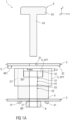
- Figure 1A shows a schematic representation of a first embodiment of a device 1 for compensating tolerances, in particular axial tolerances, in particular a height gap S, between two components to be connected to one another.
- the device 1 is intended, for example, for attaching a first component 2, for example a bearing bracket, an electronic part, a light, a decorative part, to a second component 3, for example a door panel, a supporting structure or a body structure of a vehicle.
- the device 1 comprises at least one hollow cylindrical base element 4 and a hollow cylindrical compensating element 5.
- the hollow cylindrical base element 4 is designed as a holding element for the first component 2.
- the first component 2 has at least one or more recesses (not shown in detail).
- the base element 4 comprises at least one or more flexible holding lugs 41, which reach through the recesses and abut against an underside of the first component 2.
- the device 1 further comprises a connecting element 6 which extends at least through a first cavity H1 of the device 1 in order to connect the first component 2 and the second component 3 to one another.
- the first cavity H1 has an inner contour 51 in cross section.
- the connecting element 6 has an outer contour 61 in cross section.
- the first cavity H1 is formed by the hollow interior of the compensating element 5.
- the inner contour 51 is formed on the inner wall of the compensating element 5.
- connecting element 6 extends through a second cavity H2 which is formed by the hollow interior of the base element 4.
- the base element 4 is arranged coaxially in the compensation element 5.
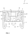
- the compensation element 5 can be arranged coaxially in the base element 4, as shown in Figure 4 is shown.
- the inner contour 51 (as in Figures 2A to 2D shown) has in cross section at least one bulge 511 extending radially outwards, in particular protruding from the inner circumference.
- the inner contour 51 has a plurality of bulges 511 evenly distributed around the inner circumference of the compensating element 5.
- At least one or more bulges 611 can be provided on the outer contour 61 of the connecting element 6, as in Figures 2E, 2F shown.
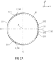
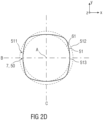
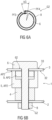
- FIG 2A A first embodiment of the inner contour 51 and the outer contour 61 is shown in a plan view from below.
- the outer contour 61 of the connecting element 6 is circular, in particular round.
- the inner contour 51 of the Compensating element 5 according to Figure 2A has three bulges 511, which are arranged in particular evenly distributed on the inner circumference of the compensating element 5.
- Figure 2B shows the inner contour 51 and the outer contour 61 according to Figure 2A in top view.
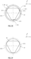
- Figure 2C shows a second embodiment of the inner contour 51 and the outer contour 61 in a plan view from below.
- the outer contour 61 is circular, in particular round.
- the inner contour 51 according to Figure 2C has four bulges 511, which are arranged in particular evenly distributed on the inner circumference of the compensating element 5.
- Figure 2D shows the inner contour 51 and the outer contour 61 according to Figure 2C in top view.
- Figure 2E shows a third embodiment of the inner contour 51 and the outer contour 61 in a plan view from below.
- the inner contour 51 is circular, in particular round.
- the outer contour 61 according to Figure 2E has three bulges 611, which are arranged in particular evenly distributed on the outer circumference of the connecting element 6.
- Figure 2F shows the inner contour 51 and the outer contour 61 according to Figure 2C in top view.
- the inner contour 51 of the compensating element 5 is cylindrical for all embodiments.
- the respective inner contour 51 of the various embodiments is conical or truncated cone-shaped in longitudinal section with a first radius 512 and a second radius 513.
- the first radius 512 is larger than the second radius 513, as in Figure 7A and 8A shown.
- the first radius 512 is, for example, circular.
- the second radius 513 is, for example, triangular or trilobular, as in Figures 2A and 2B shown, or square, as in Figures 2C and 2D.
- the bulges 511 on the inner circumference of the compensating element 5 or the bulges 611 of the connecting element 6 extend in the longitudinal extension of the compensating element 5 and the connecting element 6, in particular over a Figure 3B compensation section 523 shown.
- the respective bulge 511 or 611 can be partially circular or circular segment-shaped or can be designed as a spherical bulge. If several bulges 511 or 611 are provided, they all have the same shape.
- the compensating element 5 is designed in one piece.
- the compensating element 5 is designed without springs.
- the compensating element 5 has no spring elements.
- the inner contour 51 differs from the outer contour 61 in such a way that when the inner contour 51 and the outer contour 61 are concentrically aligned with each other, at least one radial projection 7 is present, as is the case in the various embodiments in Figures 2A to 2E is shown.
- Such a design of the contours with at least one radial projection 7 and/or integrated driver 50, in particular an integrated driver section, enables a targeted frictional connection between the connecting element 6 and the compensating element 5, at least in sections.
- at least one section of the connecting element 6 can be used to maintain a distance between the components 2, 3 to be connected.
- This enables a spring-free design of the device compared to conventional compensating devices.
- the integrated driver 50 is formed on the compensating element 5 in the device 1.
- the interaction of the inner contour 51 and the outer contour 61 provides a frictional connection and/or positive connection, whereby the torque of the connecting element 6 is transmitted to and exerted on the compensating element 5.
- the number of components of the device according to the invention is reduced.
- Figure 1A shows the device 1 in a partially assembled state in a starting position AP1, in which the compensating element 5 is arranged at a distance according to a height gap S from the second component 3.
- the compensating element 5 comes into a first threaded engagement G1 with the base element 4 at least during assembly of the device 1, wherein the compensating element 5 can be moved by rotation relative to the base element 4 from the starting position AP1 into a compensating position AP2 to compensate for the height gap S in a first compensating movement AB1, as is shown by the sequence of Figures 1A and 1B is shown.
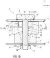
- Figure 1B shows the device 1 in the compensation position AP2, in which the height gap S is compensated and the two components 2 and 3 are connected to each other by means of a connecting element 6, in particular by means of a clamping connection.
- the connecting element 6 is, for example, a connecting screw which extends at least through a first cavity H1 and a second cavity H2 of the device 1 in order to connect the first component 2 and the second component 3 to one another.
- the connecting element 6 comes into a second threaded engagement G2 with one of the components 2, 3 and/or a first nut element 8, in particular for connecting, in particular clamping, the two components 2 and 3 to one another.
- a second nut element 9 is provided for synchronizing the first thread engagement G1 and the second thread engagement G2 when assembling the device 1.
- the second nut element 9 is arranged in the compensating element 5 in such a way that it is at least partially independent of the compensating element 5 and axially relative to it, in particular according to a second compensating movement AB2, as described in more detail below.
- the assembly process is as follows:
- the base element 4 and the compensating element 5 are arranged in the screwed state with one another on the first component 2, in particular clipped, for example connected to the first component 2 by means of retaining lugs 41.
- the second nut element 9 is arranged in a rotationally fixed manner in a receptacle 52, in particular in a receptacle section 522, of the compensating element 5.
- the second component 3 is arranged with a through opening 31 concentrically to the opening of the receptacle 52.
- the second nut element 9 is arranged in a rotationally fixed manner in the compensating element 5.
- the connecting element 6 is then further inserted into the compensating element 5 and comes into contact with a non-circular inner contour 51, in particular with the bulges 511, of the compensating element 5, as can be seen from the examples according to Figures 2A to 2D Alternatively, as for example in Figures 2E, 2F As shown, the connecting element 6 can have a non-circular outer contour 61, in particular with the bulges 611, and the inner contour 51 can be circular. Alternatively, instead of the non-circular inner contour 51, a conventional driving element (not shown in more detail), in particular a spring element, can be arranged in the compensating element 5.
- first compensating movement AB1 in that the non-circular inner contour 51 or the spring element is carried along by the connecting element 6 the compensating element 5 is brought into contact with the second component 3, as shown in the Figure 1B is shown.
- the connecting element 6 and the compensating element 5 come into a driving engagement by the integrated driver 50 and/or the radial projection 7 for the first, in particular axial, compensating movement AB1.
- the compensating element 5 moves against the insertion direction of the connecting element 6 and relative to the base element 4.
- This first compensating movement AB 1 in the axial direction serves to compensate for axial tolerances between the two components 2 and 3.
- the maximum length of the first compensating movement AB 1 corresponds approximately to the height gap S.
- the connecting element 6 thereby comes into frictional engagement with the inner contour 51 of the compensating element 5 through the integrated driver 50 and/or the radial projection 7.
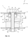
- the connecting element 6 transmits a torque to the compensating element 5, so that the compensating element 5 moves in the opposite direction to the insertion direction of the connecting element 6 and relative to the second nut element 9 and the base element 4 axially in the direction of the second component 3 according to the first compensating movement AB 1 until the compensating element 5 strikes the underside 32 of the second component 3, as shown in Figure 1B or 1C shown.
- This position corresponds to the compensation position AP2.
- This movement of the compensation element 5 when the connecting element 6 is screwed into the device 1 represents the first compensation movement AB 1, in which the compensation element 5 is moved axially in the direction of the second component 3 relative to the base element 4 and to the components 2 and 3. This compensates for axial tolerances between the components 2 and 3.
- the second nut element 9 is arranged in the compensating element 5 in such a way that it can be carried along during this first compensating movement AB1 of the compensating element 5.
- the second nut element 9 has moved relative to the base element 4 and the components 2 and 3, but not axially relative to to the compensating element 5.
- the second nut element 9 can be arranged in a recess 52 in the compensating element 5 so that it can move axially upwards and downwards, so that the compensating element 5 does not necessarily take the second nut element 9 with it.
- the second nut element 9 is therefore moved axially relative to the compensating element 5 and independently of it in accordance with the second compensating movement AB2 as a result of the thread engagement between the second nut element 9 and the connecting element 6.
- the second nut element 9 is moved axially independently of the compensating element 5 in the opposite direction to the insertion direction of the connecting element 6 until the thread of the connecting element 6 engages in the thread of the first nut element 8.
- the maximum length of the second compensating movement AB2 corresponds approximately to a synchronization height S1.
- a torque is exerted on the second nut element 9 as a result of the third thread engagement G3 between the connecting element 6 and the second nut element 9, which overcomes the positive connection on the longitudinal webs 524, so that the second nut element 9 is rotated axially in or out of the receiving section 522 against the insertion direction of the connecting element 6.
- the second nut element 9 is axially rotated in the direction of the flange surface and independently of the compensating element 5 and base element 4 in the receiving section 522 or at least partially out of it.
- the second nut element 9 is moved axially in the receiving section 522 until the thread of the connecting element 6 engages or threads into the thread of the first nut element 8. This movement serves to synchronize of the threads of the second thread engagement G2 and represents the second compensating movement AB2.
- the synchronization length can, under certain circumstances, be up to a rotation of 360° until the threads mesh.
- This synchronization length according to the second compensating movement AB2 has a corresponding adjustable synchronization height S1 of the second nut element 9.
- One rotation can, for example, be approximately one thread pitch. This one thread pitch can in turn correspond approximately to the synchronization height S1 and/or the height gap S.
- the second compensation movement AB2 does not completely compensate for the height gap S, because, for example, only half a thread pitch is necessary for the connecting element 6 to thread into the first nut element 8, in particular for their threads to mesh.
- the synchronization height S1 is smaller than the height gap S, as shown in Figure 1B is shown.
- the torque of the fastening process of the two components 2 and 3 can, under certain circumstances, lead to a force flow KF1 of a compressive stress that is different from conventional clamp connections, in particular to a clamp connection (also called clamping) between the connecting element 6 and the second nut element 9, in particular between the screw head 63 and the second nut element 9.
- the connecting element 6 is subjected to a tensile stress ZS in the assembled state of the device 1.
- This modified power flow KF1 is in Figure 1C shown.
- the second nut element 9 comes into contact with the second component 3, so that the tensile force of the connecting element 6 clamps the second nut element 9 to the second component 3 and fixes them together.
- a type of settling behaviour between the base element 4 and the compensating element 5 can occur during assembly and thus during the screwing-in process or later in the assembled state, for example when plastic parts are involved, so that the changed force flow KF1 always occurs in the device 1.
- the second nut element 9 is arranged in the recess 52 of the compensating element 5 in such a way that when the connecting element 6 is screwed into the device 1, this second nut element 9 comes into a third threaded engagement G3 with the connecting element 6, as a result of which the second nut element 9 is moved at least in sections independently of the compensating element 5 and axially relative to it when the connecting element 6 is screwed into the first component 2 and/or the first nut element 8, as described in detail above.
- the compensating element 5 and the base element 4 are located outside the changed force flow KF1 of the second nut element 9 with the connecting element 6. Due to the force connection of the connecting element 6 with the second nut element 9 via the third thread engagement G3, the second nut element 9 is 5 is moved axially in the device 1, which enables easy synchronization of the subsequent first and second thread engagements G1 and G2.
- the inner contour 51 differs from the outer contour 61 in such a way that when the inner contour 51 and the outer contour 61 are concentrically aligned with each other, radial projections 7 and/or integrated drivers 50 are formed by means of the bulges 511 or 611, as shown in Figure 2A to 2E is shown.
- Such a design of the contours with at least one radial projection 7 and/or with at least one integrated driver 50 enables a targeted frictional connection between the connecting element 6 and the compensating element 5, at least in sections.
- at least one section of the connecting element 6 can be used to maintain a distance between the components 2, 3 to be connected.
- This enables a spring-free design of the device compared to conventional compensating devices.
- the inner contour 51 in particular a non-circular inner contour 51, the radial projection 7 and/or the integrated driver 50 is formed on the compensating element 5 in the device 1.
- the interaction of the inner contour 51 and the outer contour 61 creates a frictional connection, whereby the torque of the connecting element 6 is transmitted to and exerted on the compensating element 5.
- the number of components of the device 1 according to the invention is reduced.
- Figures 2A and 2B show in a simplified schematic representation in cross section the inner contour 51 of the compensating element 5 and the outer contour 61 of the connecting element 6.
- the Figure 2A or 2B The inner contour 51 shown and the outer contour 61 lie in a plane which is spanned by two axes B and C, wherein the axis B and the axis C are aligned perpendicular to each other and perpendicular to the longitudinal axis A of the device 1.
- the longitudinal axis A passes through the intersection point of the two axes B and C.
- the respective inner contour 51 is essentially non-circular.
- the respective outer contour 61 is essentially circular.
- the inner contour 51 is trilobular and has three round corners, also referred to as triangular-round.
- the inner contour 51 can be oval or elliptical, in which case only two radial projections 7 are formed instead of three radial projections 7 and/or integrated drivers 50.
- the inner contour 51 can also be formed in such a way that four radial projections 7 and/or integrated drivers 50 are formed, as in Figure 2B shown. Such an inner contour 51 is also called a square-round.
- the outer contour 61 may be non-circular and the inner contour 51 may be substantially circular, as in Figures 2E and 2F shown.
- a first nut element 8 is provided on the underside of the first component 2.
- the first nut element 8 can be a separate element.
- the first nut element 8 can be welded to the first component 2.
- the first component 2 and the second component 3 each comprise associated through openings 21 and 31 for the connecting element 6.
- the first component 2 itself can have an internal thread as a nut, wherein the internal thread is formed in the associated through opening 21.
- the first component 2 and the second component 3 are screwed together.
- the device 1 is arranged on the first component 2, for example by means of the base element 4, and held there, for example by means of the holding lugs 41.
- the second component 3 is arranged on the side of the compensating element 5 facing away from the base element 4.
- the connecting element 6 is then guided through the through-opening 31 in the second component 3, the first cavity H1 and the second cavity H2 as well as the through-opening 21 in the first component 2 and screwed into the first component 2 and/or the first nut element 8.
- the compensating element 5 and the connecting element 6 come into frictional engagement with one another at least in sections, in particular in the area of the inner contour 51 and the outer contour 61.
- the compensating element 5 and the connecting element 6 thus come into frictional engagement with one another in such a way that when the two components 2 and 3 are connected to one another, a torque exerted by the connecting element 6 can be transmitted to the compensating element 5.
- the undesirable height gap S between the two components 2 and 3 to be connected is compensated and closed by moving the compensating element 5 axially from a starting position AP1 to the compensating position AP2 according to arrow PF1 during the screwing.
- the compensating element 5 is arranged at a distance according to the height gap S from a bottom side 32 of the second component 3, as shown in Figure 1A
- the compensation position AP2 (shown in dashed lines), the compensation element 5 rests against the underside 32 of the second component 3, as shown in Figure 1B or 1C is shown.
- the base element 4 and the compensating element 5 can each be made of a plastic material. Alternatively, other materials, such as metals, can also be provided. The base element 4 and the compensating element 5 can be made of the same material or of different materials.
- the inner contour 51 and the outer contour 61 can also come into a positive connection with one another.
- the inner contour 51 and/or the outer contour 61 can be provided with an engagement structure (not shown in detail).
- the inner contour 51 and/or the outer contour 61 can be provided with a friction layer, for example a fine- or coarse-grained top layer. This The frictional connection between the connecting element 6 and the compensating element 5 is increased in the area of the interlocking contours.
- the device 1 comprises a second nut element 9.
- the second nut element 9 serves to synchronize compensating movements of the compensating element 5 to the base element 4 and of the connecting element 6 to the compensating element 5 and to the first nut element 8, as previously described for the Figures 1B and 1C described.
- the second nut element 9 is arranged in a recess 52 of the compensating element 5.
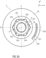
- Figures 3A and 3B show a top view and a perspective view of an embodiment for the axial compensation element 5.
- the axial compensation element 5 has a flange 53.
- the flange 53 is designed as a projection or a radial projection on a hollow cylindrical shaft 54.
- the recess 52 is stepped.
- the recess 52 has a first compensating section 521 for the second nut element 9, a receiving section 522 for the second nut element 9 and a second compensating section 523 for the compensating element 5.
- the second compensation section 523 has a non-circular inner contour 51, in particular a trilobular shape in cross section, which enables a frictional engagement with the connecting element 6 when it is screwed in.
- the inner contour 51 can also have another suitable cross-sectional shape, in particular a two-, four- or multi-cornered round shape.
- the inner contour 51 also has a conical shape in longitudinal section. This conical shape supports the frictional engagement of the connecting element 6 and compensation element 5 during the tolerance compensating movement between the two components 2 and 3.
- the inner contour 51 can be provided with an engagement structure not shown in detail, in particular a friction layer.
- the second nut element 9 is arranged in its initial position AP1 in the receiving section 522 in a form-fitting manner.
- the receiving section 522 has a number of longitudinal webs 524, which are distributed in particular symmetrically.
- the second nut element 9 is inserted, in particular pressed, into the receiving section 522 during assembly of the device 1, wherein the longitudinal webs 524 form a form-fitting connection between the second nut element 9 and the compensating element 5.
- the second nut element 9 is, for example, a hexagon nut.
- the receiving section 522 has a corresponding hexagon contour 525 on the inside and at least in sections.
- a slot-shaped recess 531 is provided in the area of the flange 53. This forms a flexible securing arm 532 which Figure 7B is explained in more detail.
- the longitudinal webs 524 extend along the longitudinal axis A at least in some areas in the region of the receiving section 522.
- the longitudinal webs 524 have a decreasing height in the direction of the first compensation section 521.
- the longitudinal webs 524 have a shape and/or dimensions such that the second nut element 9 is arranged in the receiving section 522 at least in a form-fitting manner, in particular in the direction of rotation of the connecting element 6.
- the second nut element 9 is arranged in a friction-fitting manner, in particular in the axial direction along the longitudinal axis A, in the receiving section 522.
- the second nut element 9 has a height which approximately corresponds to the height of the receiving section 522.
- the connecting element 6 When the connecting element 6 is inserted into the second nut element 9, they come into threaded engagement with one another.
- the second nut element 9 has a corresponding internal thread for this purpose.
- the connecting element 6 is designed as a connecting screw or a threaded bolt with a corresponding external thread.
- the inner contour 51 of the compensating element 5 can be designed to be flexible or resilient.
- the compensating element 5 comprises an annular groove 56 on its end face opposite the flange 53.
- the annular groove 56 serves in particular to prevent material accumulation during an injection molding process of a compensating element 5 made of plastic.
- such a compensating element 5 made of plastic with an annular groove 56 enables a resilient uniform thickness shape.
- the compensating element 5 also has a compensating thread 55 in the embodiment shown according to Figures 3A and 3B .
- the compensating thread 55 is in the respective embodiment according to Figures 1A-1C , 5B, 6B an internal thread and in the respective embodiment according to Figures 3B , 4 , 7A , 8A an external thread.
- the base element 4 has an associated base element thread 42, which is shown by way of example in the following Figures 4 , 7A and 8A
- the basic element thread 42 is an internal thread.
- the basic element thread 42 is an external thread.
- the basic element thread 42 can be designed as a thread with a single thread crest.
- the basic element thread 42 can also have several threads with corresponding thread crests, in particular two thread crests. With only one thread, an opening/closing tool is advantageously possible and thus cost-effective production. With two or more threads, however, a rotatable core is also required for demolding.
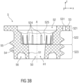
- Figure 4 shows a sectional view of the device 1 without connecting element 6.
- the second nut element 9 is arranged in the initial position AP1 in the receiving section 522 in a form-fitting manner.
- the first compensation section 521 represents the synchronization height S1 which the second nut element 9 axially compensates for when the connecting element 6 is screwed into the first nut element 8, independently of the compensation element 5, in order to synchronize the threads in accordance with the second compensation movement AB2, without the compensation element 5 being moved axially, as is the case for the Figures 1B and 1C described and shown.
- This second compensating movement AB2 serves to synchronize the thread engagements, in particular the compensating thread engagement between compensating element 5 and base element 4 and the fastening engagement between connecting element 6 and first nut element 8.
- the second nut element 9 is arranged, in particular pressed, in the recess 52 in the compensating element 5 at least the synchronization height S1, in particular at least one thread pitch of the first thread engagement G1, lower than the front or flange surface of the compensating element 5.
- the synchronization height S1 corresponds to at least one thread pitch.
- This internal position of the second nut element 9 in the starting position AP1 enables the axial movement of the second nut element 9 without axial movement of the compensation element 5.
- the second nut element 9 can also move at least partially out of the recess 52.
- the second nut element 9 can move out of the recess 52 during the second compensating movement AB2 until the second nut element 9 strikes the underside 32 of the second component 3, as is shown by way of example in Figures 1C and 6B is shown.
- the sole movement of the second nut element 9 when screwing the connecting element 6 into the device 1, in particular into the first nut element 8, represents the second compensating movement AB2 relative to the compensating element 5 and base element 4 as well as to the components 2 and 3.
- Figure 5A shows in a simplified schematic cross-sectional representation the area of the second thread engagement G2 between the connecting element 6 and the first nut element 8, after the compensating element 5 is placed in its compensating position AP2 as a result of the first compensating movement AB1 and before their thread starts thread or engage with each other when the connecting element 6 is screwed into the first nut element 8.
- ⁇ G thread offset
- Figure 5B shows the device 1 in the assembled state, wherein the compensating element 5 is set in its compensating position AP2 due to its first compensating movement AB1 during assembly. Due to the thread offset ⁇ G, no synchronization of the thread starts of the second thread engagement G2 is required. Thus, in this embodiment, no second compensating movement AB2 of the second nut element 9 takes place. The second nut element 9 remains in its starting position AP1. The compensating element 5 is set in its compensation position AP2 and rests on the underside 32 of the second component 3.
- the connecting element 6 can be screwed into the first nut element 8 until a head underside 62 of the connecting element 6 strikes an upper side 33 of the second component 3.
- the two components 2 and 3 are connected to one another by means of the device 1 in a way that compensates for axial tolerances.
- the first nut element 8 can be formed separately or fastened to the first component 2, in particular welded.
- the first component 2 has a component thread in the through-opening 21, into which the connecting element 6 engages in a connecting manner, so that the first nut element 8 can be omitted.
- Figure 6A shows in a simplified schematic cross-sectional representation a further example of the area of the second thread engagement G2 between the connecting element 6 and the first nut element 8, after the compensating element 5 is set in its compensating position AP2 as a result of the first compensating movement AB1 and before the thread starts of the second thread engagement G2 thread or engage with each other when the connecting element 6 is screwed into the first nut element 8.
- the compensating element 5 is already set in its compensating position AP2.
- the second nut element 9 is therefore moved axially relative to the compensating element 5 and independently of it in accordance with the second compensating movement AB2 as a result of the third thread engagement G3 between the second nut element 9 and the connecting element 6.
- the second nut element 9 is moved axially independently of the compensating element 5 against the insertion direction of the connecting element 6 until the thread of the connecting element 6 engages in the thread of the first nut element 8.
- the maximum length of the second compensating movement AB2 corresponds approximately to a synchronization height S1.
- the synchronization height S1 can, under certain circumstances, be up to a rotation of 360° before the threads mesh.
- One rotation can, for example, correspond approximately to one thread pitch.
- This one thread pitch can, in turn, correspond approximately to the synchronization height S1 and/or the height gap S.
- Figure 6B shows the device 1 in the assembled state, whereby due to the large thread offset ⁇ G both the compensating element 5 and the second nut element 9 are set in the compensating position AP2.
- the connecting element 6 is screwed into the first nut element 8 by a further screwing movement of the connecting element 6 into the device 1 until the head bottom 62 of the connecting element 6 is in contact with the top 33 of the second component 3.
- the two components 2 and 3 are connected to one another by means of the device 1 in a way that compensates for axial tolerances.
- the first nut element 8 can be formed separately or fastened to the first component 2, in particular welded.
- the first component 2 has a component thread in the through-opening 21, into which the connecting element 6 engages in a connecting manner, so that the first nut element 8 can be omitted.
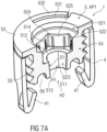
- Figures 7A and 7B show in perspective and partially sectioned view the device 1 in the assembled state without connecting element 6 and second nut element 9, wherein the compensating element 5 is set in the starting position AP1.
- the inner contour 51 is conical with the first radius 512 at the upper end of the second compensation section 523 and the second radius 513 at the lower end of the second compensation section.
- the first radius 512 is larger than the second radius 513.
- a chamfer 514 can be introduced into the upper edge of the second compensation section 523.
- a free end 533 of the securing arm 532 of the compensating element 5 has a projection 534 which is in engagement with a securing recess 43 in the base element 4 before assembly with the components 2 and 3 takes place.
- the engagement of the projection 534 in the securing recess 43 forms an anti-twist device between the compensating element 5 and the base element 4.
- This anti-twist device between the compensating element 5 and the base element 4 serves as a bearing lock during pre-assembly of the device 1 on the first component 2 and/or as a transport lock for the device 1 before assembly on the components 2 and 3.
- Figures 8A and 8B show in perspective and partially sectioned view the device 1 in the assembled state without connecting element 6 and second nut element 9, wherein the compensating element 5 is set in the compensating position AP2.
Landscapes
- Engineering & Computer Science (AREA)
- General Engineering & Computer Science (AREA)
- Mechanical Engineering (AREA)
- Physics & Mathematics (AREA)
- Geometry (AREA)
- Bolts, Nuts, And Washers (AREA)
- Mutual Connection Of Rods And Tubes (AREA)
Description
Die Erfindung betrifft eine Vorrichtung zum Ausgleichen von Toleranzen zwischen zwei miteinander zu verbindenden Bauteilen.The invention relates to a device for compensating tolerances between two components to be joined together.
Bekannte Vorrichtungen zum Ausgleichen von Toleranzen zwischen zwei Bauteilen (auch kurz Ausgleichsvorrichtung genannt) sind durch ein Grundelement oder - körper und ein axiales Ausgleichselement, zum Beispiel metallische Gewindehülsen, gebildet, welche in einem Gewindeeingriff, zum Beispiel Linksgewindeeingriff, stehen. In dem axialen Ausgleichselement ist üblicherweise ein Federelement angeordnet, welches einen Reibschluss zwischen einem durch die Ausgleichsvorrichtung hindurchgeführten und ein weiteres Gewinde (Rechtsgewinde) aufweisenden Verbindungselement und dem axialen Ausgleichselement herstellt, so dass beim Anziehen, zum Beispiel Drehen, des Verbindungselements ein Drehmoment auf das axiale Ausgleichselement ausgeübt wird, welches ein axiales Herausdrehen des Ausgleichselements aus dem Grundelement entgegen der Einführrichtung der Verbindungsschraube bewirkt und somit axiale Toleranzen ausgleicht.Known devices for compensating tolerances between two components (also called compensating devices for short) are formed by a base element or body and an axial compensating element, for example metallic threaded sleeves, which are in a threaded engagement, for example left-hand thread engagement. A spring element is usually arranged in the axial compensating element, which creates a frictional connection between a connecting element that passes through the compensating device and has another thread (right-hand thread) and the axial compensating element, so that when the connecting element is tightened, for example rotated, a torque is exerted on the axial compensating element, which causes the compensating element to be axially unscrewed from the base element against the insertion direction of the connecting screw and thus compensates for axial tolerances.
Solche Vorrichtungen sind zum Beispiel aus der
Der Erfindung liegt die Aufgabe zugrunde, eine besonders einfach aufgebaute Vorrichtung zum Ausgleichen von Toleranzen zwischen zwei miteinander zu verbindenden Bauteilen anzugeben.The invention is based on the object of specifying a particularly simply constructed device for compensating tolerances between two components to be connected to one another.
Die Aufgabe wird erfindungsgemäß mit einer Vorrichtung zum Ausgleichen von Toleranzen zwischen zwei miteinander zu verbindenden Bauteilen mit den Merkmalen des Patentanspruchs 1 gelöst.The object is achieved according to the invention with a device for compensating tolerances between two components to be connected to one another with the features of
Vorteilhafte Weiterbildungen sind Gegenstand der abhängigen Patentansprüche.Advantageous further developments are the subject of the dependent patent claims.
Die erfindungsgemäße Vorrichtung zum Ausgleichen von Toleranzen zwischen zwei miteinander zu verbindenden Bauteilen umfasst zumindest ein hohlzylindrisches Grundelement, ein hohlzylindrisches Ausgleichselement, das mit dem Grundelement in Gewindeeingriff steht und das durch Verdrehen relativ zu dem Grundelement aus einer Ausgangsposition in eine Ausgleichsposition bewegbar ist, und ein sich durch einen Hohlraum des Ausgleichselements hindurch erstreckendes Verbindungselement zum Verbinden der beiden Bauteile, wobei der Hohlraum im Querschnitt eine Innenkontur und das Verbindungselement im Querschnitt eine Außenkontur aufweisen, und wobei sich die Innenkontur von der Außenkontur derart unterscheidet, dass bei konzentrischer Ausrichtung der Innenkontur und der Außenkontur mindestens ein radialer Überstand vorliegt.The device according to the invention for compensating tolerances between two components to be connected to one another comprises at least one hollow cylindrical base element, a hollow cylindrical compensating element which is in threaded engagement with the base element and which can be moved from an initial position into a compensating position by rotation relative to the base element, and a connecting element extending through a cavity of the compensating element for connecting the two components, wherein the cavity has an inner contour in cross section and the connecting element has an outer contour in cross section, and wherein the inner contour differs from the outer contour in such a way that when the inner contour and the outer contour are concentrically aligned, there is at least one radial projection.
Insbesondere ermöglicht die Ausgestaltung mit mindestens einem radialen Überstand zumindest abschnittsweise einen gezielten Kraftschluss zwischen dem Verbindungselement und dem Ausgleichselement. Dadurch kann zumindest ein Abschnitt des Verbindungselements, zum Beispiel einer Verbindungsschraube oder eines Gewindebolzens, zur Einhaltung eines Abstands zwischen den zu verbindenden Bauteilen genutzt werden. Hierdurch ist gegenüber herkömmlichen Ausgleichsvorrichtungen eine federfreie Ausbildung der Vorrichtung ermöglicht. Mit anderen Worten: Auf ein separates Federelement als Mitnehmer zum Herausdrehen des Ausgleichselements kann verzichtet werden.In particular, the design with at least one radial projection enables a targeted force connection between the connecting element and the compensating element, at least in sections. This means that at least one section of the connecting element, for example a connecting screw or a threaded bolt, can be used to maintain a distance between the components to be connected. This enables the device to be designed without springs compared to conventional compensating devices. In other words: a separate spring element as a driver for unscrewing the compensating element can be dispensed with.
Eine weitere erfindungsgemäße Vorrichtung zum Ausgleichen von Toleranzen zwischen zwei miteinander zu verbindenden Bauteilen umfasst zumindest ein hohlzylindrisches Grundelement, ein hohlzylindrisches Ausgleichselement, das mit dem Grundelement in Gewindeeingriff steht und das durch Verdrehen relativ zu dem Grundelement aus einer Ausgangsposition in eine Ausgleichsposition bewegbar ist, und ein sich durch einen Hohlraum des Ausgleichselements hindurch erstreckendes Verbindungselement zum Verbinden der beiden Bauteile, wobei der Hohlraum im Querschnitt eine Innenkontur und das Verbindungselement im Querschnitt eine Außenkontur aufweisen, und wobei die Innenkontur oder die Außenkontur im Querschnitt mindestens eine sich radial erstreckende Auswölbung aufweist und wobei bei konzentrischer Ausrichtung der Innenkontur und der Außenkontur durch die mindestens eine Auswölbung der Außenkontur oder Innenkontur im Querschnitt des Ausgleichselements mindestens ein radialer Überstand und/oder ein integrierter Mitnehmer, insbesondere ein integrierter Mitnahmeabschnitt, gebildet ist.A further device according to the invention for compensating tolerances between two components to be connected to one another comprises at least one hollow cylindrical base element, a hollow cylindrical compensating element which is in threaded engagement with the base element and which can be adjusted by rotation relative to the base element is movable from a starting position into a compensating position, and a connecting element extending through a cavity of the compensating element for connecting the two components, wherein the cavity has an inner contour in cross-section and the connecting element has an outer contour in cross-section, and wherein the inner contour or the outer contour has at least one radially extending bulge in cross-section and wherein, with concentric alignment of the inner contour and the outer contour, at least one radial projection and/or an integrated driver, in particular an integrated driver section, is formed by the at least one bulge of the outer contour or inner contour in the cross-section of the compensating element.
Bei der erfindungsgemäßen Vorrichtung ist mittels der Auswölbung durch Reibschlusskontakt der integrierte Mitnehmer und/oder durch Formschlusskontakt der radiale Überstand gebildet. Beispielsweise ist die Auswölbung durch eine nicht kreisförmige Innenkontur oder eine nicht kreisförmige Außenkontur gebildet. Durch die Wechselwirkung von Innenkontur und Außenkontur mittels der Auswölbung ist zumindest ein Kraftschluss direkt zwischen dem Verbindungselement und dem Ausgleichselement gegeben, wodurch das Drehmoment des Verbindungselements auf das Ausgleichselement übertragen und ausgeübt wird. Somit ist die Anzahl der Komponenten der erfindungsgemäßen Vorrichtung reduziert. Die erfindungsgemäße Vorrichtung ist besonders einfach aus wenigen Teilen aufgebaut und in der Herstellung kostengünstig. Dabei erfolgt der Toleranzausgleich zwischen den zwei miteinander zu verbindenden Bauteilen mit hoher Genauigkeit und nur geringem Aufwand.In the device according to the invention, the integrated driver is formed by means of the bulge through frictional contact and/or the radial projection is formed through positive contact. For example, the bulge is formed by a non-circular inner contour or a non-circular outer contour. The interaction of the inner contour and outer contour by means of the bulge provides at least one force connection directly between the connecting element and the compensating element, whereby the torque of the connecting element is transmitted to and exerted on the compensating element. The number of components of the device according to the invention is thus reduced. The device according to the invention is particularly simple and consists of just a few parts and is inexpensive to manufacture. The tolerance compensation between the two components to be connected to one another is carried out with high precision and only with little effort.
Beispielsweise ist die Auswölbung der Innenkontur oder der Außenkontur teilkreisförmig oder kreissegmentförmig oder als sphärische Auswölbung ausgebildet. Bevorzugt ist das Ausgleichselement einteilig, insbesondere ohne einen zusätzlichen Mitnehmer oder ein zusätzliches Federelement, ausgebildet. Beispielsweise kann die Vorrichtung federfrei ausgebildet sein. Anstelle eines separaten Mitnehmers bildet die mindestens eine Auswölbung des Ausgleichselements oder des Verbindungselements den radialen Überstand und/oder den integrierten Mitnehmer, insbesondere den integrierten Mitnehmerabschnitt.For example, the bulge of the inner contour or the outer contour is formed in the shape of a part-circle or a circular segment or as a spherical bulge. The compensating element is preferably formed in one piece, in particular without an additional driver or an additional spring element. For example, the device can be formed without springs. Instead of a separate driver, the at least one bulge of the Compensating element or the connecting element, the radial projection and/or the integrated driver, in particular the integrated driver section.
Eine Weiterbildung sieht vor, dass, wenn die Innenkontur nicht kreisförmig ausgebildet ist, die Außenkontur kreisförmig ausgebildet ist. Alternativ kann die Innenkontur kreisförmig und die Außenkontur nicht kreisförmig ausgebildet sein. Beispielsweise ist die Innenkontur im Querschnitt oval, elliptisch oder trilobular, insbesondere dreiecksrund, oder vierecksrund und die Außenkontur kreisförmig, insbesondere kreisrund, oder umgekehrt ausgebildet. Durch eine solche Kontur und Gegenkontur von Ausgleichselement und Verbindungselement ist in einfacher Art und Weise ohne zusätzliche Mittel ein besonders wirkungsvoller Kraftschluss und/oder Formschluss und damit ein mitnehmender Eingriff ermöglicht. Aufgrund des zwei- oder mehrfachen, insbesondere dreifachen oder vierfachen, radialen Überstandes und/oder integrierten Mitnehmerabschnitts zwischen der Innen- und Außenkontur kann der einzelne radiale Überstand beziehungsweise der einzelne integrierte Mitnehmerabschnitt möglichst gering ausgelegt sein, um einen hinreichenden Kraftschluss beziehungsweise Formschluss, insbesondere eine Selbsthemmung, zwischen den Konturen zu erzielen. Dabei sind die Innenkontur und die Außenkontur derart korrespondierend zueinander ausgebildet, dass trotz Selbsthemmung zwischen den Konturen ein gewünschtes Verstellen der Position des Ausgleichselements relativ zum Grundelement und somit ein Toleranzausgleich zwischen den Bauteilen und ein Einstellen der Position des einen Bauteils relativ zum anderen Bauteil weiterhin ermöglicht bleibt.A further development provides that if the inner contour is not circular, the outer contour is circular. Alternatively, the inner contour can be circular and the outer contour can be non-circular. For example, the inner contour is oval, elliptical or trilobular in cross-section, in particular triangular or square, and the outer contour is circular, in particular circular, or vice versa. Such a contour and counter-contour of the compensating element and connecting element enables a particularly effective force-fit and/or form-fit and thus a driving engagement in a simple manner and without additional means. Due to the double or multiple, in particular triple or quadruple, radial projection and/or integrated driver section between the inner and outer contour, the individual radial projection or the individual integrated driver section can be designed to be as small as possible in order to achieve a sufficient force-fit or form-fit, in particular self-locking, between the contours. The inner contour and the outer contour are designed to correspond to one another in such a way that, despite self-locking between the contours, a desired adjustment of the position of the compensating element relative to the base element and thus a tolerance compensation between the components and an adjustment of the position of one component relative to the other component are still possible.
Zusätzlich kann die Innenkontur des Ausgleichselements eine Konusform aufweisen. Hierdurch ist abschnittsweise ein sicherer Kraftschluss zwischen Verbindungselement und Ausgleichselement ermöglicht. Dabei nimmt der Durchmesser der Konusform des Ausgleichselements in Einführrichtung des Verbindungselements ab. Der Kraftschluss im Bereich der Konusform zwischen Verbindungselement und Ausgleichselement nimmt in Einführrichtung des Verbindungselements und entlang einer Längserstreckung des Verbindungselements hingegen zu.In addition, the inner contour of the compensating element can have a conical shape. This enables a secure frictional connection between the connecting element and the compensating element in certain sections. The diameter of the conical shape of the compensating element decreases in the direction of insertion of the connecting element. The frictional connection in the area of the conical shape between the connecting element and the compensating element decreases in the direction of insertion of the connecting element and along a longitudinal extension of the connecting element.
In einem möglichen Ausführungsbeispiel sind die Innenkontur und die Außenkontur derart eingerichtet, dass diese zumindest beim Zusammenbau der Vorrichtung in Reibeingriff miteinander, insbesondere einen Mitnehmereingriff, gelangen. Insbesondere gelangen das Ausgleichselement und das Verbindungselement derart in einem Reibeingriff miteinander, dass, insbesondere beim Zusammenbau der Vorrichtung und dem Verbinden der beiden Bauteile miteinander, ein durch das Verbindungselement ausgeübtes Drehmoment an das Ausgleichselement übertragbar ist. Hierdurch können unerwünschte Abstände zwischen den beiden zu verbindenden Bauteilen ausgeglichen werden.In one possible embodiment, the inner contour and the outer contour are designed in such a way that they come into frictional engagement with one another, in particular a driver engagement, at least when the device is being assembled. In particular, the compensating element and the connecting element come into frictional engagement with one another in such a way that, in particular when the device is being assembled and the two components are being connected to one another, a torque exerted by the connecting element can be transferred to the compensating element. This makes it possible to compensate for undesirable distances between the two components to be connected.
Das Grundelement und das Ausgleichselement können jeweils aus einem Kunststoffmaterial gebildet sein. Alternativ können auch andere Materialien, wie beispielsweise Metalle, vorgesehen sein. Das Grundelement und das Ausgleichselement können dabei aus demselben Material oder aus unterschiedlichen Materialien gebildet sein.The base element and the compensating element can each be made of a plastic material. Alternatively, other materials, such as metals, can also be provided. The base element and the compensating element can be made of the same material or of different materials.
Je nach Größe des radialen Überstandes können die Innenkontur und die Außenkontur auch in einen Formschluss miteinander gelangen. Je größer der radiale Überstand ist, desto eher gelangen die Innenkontur und die Außenkontur über den Reibschluss hinaus in einen Formschluss miteinander.Depending on the size of the radial projection, the inner contour and the outer contour can also form a positive connection with each other. The larger the radial projection, the more likely it is that the inner contour and the outer contour will form a positive connection with each other beyond the frictional connection.
Zusätzlich kann die Innenkontur, insbesondere einschließlich deren Auswölbung, und/oder die Außenkontur, insbesondere einschließlich deren Auswölbung, mit einer Eingriffsstruktur versehen sein. Beispielsweise kann die Innenkontur und/oder die Außenkontur mit einer Reibschicht, zum Beispiel einer fein- oder grobkörnigen Oberschicht, versehen sein. Hierdurch wird der Kraftschluss zwischen dem Verbindungselement und dem Ausgleichselement erhöht.In addition, the inner contour, in particular including its bulge, and/or the outer contour, in particular including its bulge, can be provided with an engagement structure. For example, the inner contour and/or the outer contour can be provided with a friction layer, for example a fine- or coarse-grained top layer. This increases the frictional connection between the connecting element and the compensating element.
Auch können beziehungsweise kann das Ausgleichselement und/oder das Verbindungselement zumindest teilweise verformbar sein. Durch den insbesondere abschnittsweise geringen radialen Überstand und/oder die mindestens eine Auswölbung zwischen der Innenkontur und der Außenkontur kann es im zusammengebauten Zustand der Vorrichtung zu einer Verformung des Ausgleichselements und/oder des Verbindungselements kommen, insbesondere zu einer geringen Dehnung und/oder Kompression.The compensating element and/or the connecting element can also be at least partially deformable. Due to the small radial projection, particularly in some sections, and/or the at least one bulge between the inner contour and the outer contour, the compensating element and/or the connecting element can be deformed when the device is assembled, in particular by a slight expansion and/or compression.
Darüber hinaus umgeben das Ausgleichselement und das Grundelement das Verbindungselement koaxial. Das Ausgleichselement und das Grundelement weisen eine Längserstreckung auf, bei der es sich um eine Erstreckung entlang einer Längsachse handelt. Das Ausgleichselement und das Grundelement sind dabei insbesondere rotationssymmetrisch um ihre Längsachsen ausgebildet. Im zusammengebauten Zustand der Vorrichtung fallen die Längsachsen des Ausgleichselements, des Grundelements und des Verbindungselements zusammen. Darüber hinaus ist das Ausgleichselement zum Toleranzausgleich axial beweglich im Grundelement angeordnet.In addition, the compensating element and the base element coaxially surround the connecting element. The compensating element and the base element have a longitudinal extension, which is an extension along a longitudinal axis. The compensating element and the base element are in particular rotationally symmetrical about their longitudinal axes. When the device is assembled, the longitudinal axes of the compensating element, the base element and the connecting element coincide. In addition, the compensating element is arranged in the base element so that it can move axially to compensate for tolerances.
Ausführungsbeispiele der Erfindung werden anhand von Zeichnungen näher erläutert. Dabei zeigen:
- Figuren 1A bis 1C
- in schematischer Darstellung eine Ausführungsform für eine Vorrichtung zum Ausgleichen von Toleranzen zwischen zwei Bauteilen in einer Ausgangsposition mit einem auszugleichenden Höhenspalt zwischen den Bauteilen bzw. in einer Ausgleichsposition mit ausgeglichenem Höhenspalt und ausgeglichener Synchronisierhöhe,
- Figuren 2A und 2B
- jeweils in schematischer Darstellung ein erstes Ausführungsbeispiel für eine Innenkontur eines Ausgleichselements und eine Außenkontur eines Verbindungselements,
- Figuren 2C und 2D
- jeweils in schematischer Darstellung ein zweites Ausführungsbeispiel für eine Innenkontur eines Ausgleichselements und eine Außenkontur eines Verbindungselements,
- Figuren 2E und 2F
- jeweils in schematischer Darstellung ein drittes Ausführungsbeispiel für eine Innenkontur eines Ausgleichselements und eine Außenkontur eines Verbindungselements,
- Figuren 3A und 3B
- in Draufsicht bzw. in perspektivischer Ansicht eine Ausführungsform für ein Ausgleichselement,
Figur 4 in- Schnittdarstellung eine Ausführungsform für die Vorrichtung ohne Verbindungselement,
- Figuren 5A und 5B
- in schematischer Darstellung Bewegungsrichtungen von Komponenten der Vorrichtung während eines toleranzausgleichenden Verbindens der zwei Bauteile und die Vorrichtung im zusammengebauten Zustand, wobei das Ausgleichselement in einer Ausgangsposition gestellt ist,
- Figuren 6A und 6B
- in schematischer Darstellung Bewegungsrichtungen von Komponenten der Vorrichtung während eines toleranzausgleichenden Verbindens der zwei Bauteile und die Vorrichtung im zusammengebauten Zustand, wobei das Ausgleichselement in einer Ausgleichsposition gestellt ist,
- Figuren 7A und 7B
- in perspektivischer und teilgeschnittener Ansicht die Vorrichtung im zusammengebauten Zustand ohne Verbindungselement und ohne zweites Mutterelement, wobei das Ausgleichselement in einer Ausgangsposition gestellt ist, und
- Figuren 8A und 8B
- in perspektivischer und teilgeschnittener Ansicht die Vorrichtung im zusammengebauten Zustand ohne Verbindungselement und ohne zweites Mutterelement, wobei das Ausgleichselement in einer Ausgleichsposition gestellt ist.
- Figures 1A to 1C
- in schematic representation an embodiment of a device for compensating tolerances between two components in a starting position with a height gap to be compensated between the components or in a compensation position with a compensated height gap and compensated synchronization height,
- Figures 2A and 2B
- each in a schematic representation of a first embodiment for an inner contour of a compensating element and an outer contour of a connecting element,
- Figures 2C and 2D
- each in a schematic representation of a second embodiment for an inner contour of a compensating element and an outer contour of a connecting element,
- Figures 2E and 2F
- each in a schematic representation of a third embodiment for an inner contour of a compensating element and an outer contour of a connecting element,
- Figures 3A and 3B
- in plan view or in perspective view an embodiment for a compensation element,
- Figure 4 in
- Sectional view of an embodiment of the device without connecting element,
- Figures 5A and 5B
- in schematic representation directions of movement of components of the device during a tolerance-compensating connection of the two components and the device in the assembled state, wherein the compensating element is placed in a starting position,
- Figures 6A and 6B
- in schematic representation directions of movement of components of the device during a tolerance-compensating connection of the two components and the device in the assembled state, wherein the compensating element is placed in a compensating position,
- Figures 7A and 7B
- in perspective and partially sectioned view the device in the assembled state without connecting element and without second nut element, wherein the compensating element is placed in a starting position, and
- Figures 8A and 8B
- in perspective and partially sectioned view of the device in the assembled state without connecting element and without second nut element, wherein the compensating element is placed in a compensating position.
Einander entsprechende Teile sind in allen Figuren mit den gleichen Bezugszeichen versehen.Corresponding parts are provided with the same reference numerals in all figures.
Die Vorrichtung 1 umfasst zumindest ein hohlzylindrisches Grundelement 4 und ein hohlzylindrisches Ausgleichselement 5. Das hohlzylindrische Grundelement 4 ist als Halteelement für das erste Bauteil 2 ausgebildet. Hierzu weist das erste Bauteil 2 zumindest eine oder mehrere nicht näher dargestellte Aussparung/en auf. Das Grundelement 4 umfasst zumindest eine oder mehrere flexible Haltenase/n 41, welche die Aussparungen durchgreifen und an einer Unterseite des ersten Bauteils 2 haltend anschlagen.The
Die Vorrichtung 1 umfasst darüber hinaus ein Verbindungselement 6, das sich zumindest durch einen ersten Hohlraum H1 der Vorrichtung 1 hindurch erstreckt, um das erste Bauteil 2 und das zweite Bauteil 3 miteinander zu verbinden.The
Dabei weist der erste Hohlraum H1 im Querschnitt eine Innenkontur 51 auf. Das Verbindungselement 6 weist im Querschnitt eine Außenkontur 61 auf.The first cavity H1 has an
Der erste Hohlraum H1 ist durch den hohlen Innenraum des Ausgleichselements 5 gebildet. Die Innenkontur 51 ist an der Innenwandung des Ausgleichselements 5 ausgebildet.The first cavity H1 is formed by the hollow interior of the compensating
Darüber hinaus erstreckt sich das Verbindungselement 6 durch einen zweiten Hohlraum H2, der durch den hohlen Innenraum des Grundelements 4 gebildet ist.Furthermore, the connecting
Im Ausführungsbeispiel ist das Grundelement 4 koaxial im Ausgleichselement 5 angeordnet. Alternativ kann das Ausgleichselement 5 koaxial im Grundelement 4 angeordnet sein, wie dies in
Die Innenkontur 51 (wie in
In einer alternativen Ausführungsform der Vorrichtung 1 kann anstelle der Auswölbung 511 an der Innenkontur 51 des Ausgleichselements 5 mindestens eine oder mehrere Auswölbung/en 611 an der Außenkontur 61 des Verbindungselements 6 vorgesehen sein, wie in
Bei konzentrischer Ausrichtung der Innenkontur 51 des Ausgleichselements 5 und der Außenkontur 61 des Verbindungselements 6 ist im Querschnitt durch die mindestens eine Auswölbung 511 der Innenkontur 51 (
In
Die Innenkontur 51 des Ausgleichselements 5 ist für alle Ausführungsbeispiele zylinderförmig. Insbesondere ist die jeweilige Innenkontur 51 der verschiedenen Ausführungsbeispiele im Längsschnitt konusförmig oder kegelstumpfförmig mit einem ersten Radius 512 und einem zweiten Radius 513 ausgebildet. Der erste Radius 512 ist größer als der zweite Radius 513, wie in
Der erste Radius 512 ist beispielsweise kreisförmig. Der zweite Radius 513 ist beispielsweise dreiecksrund oder trilobular, wie in
Die jeweilige Auswölbung 511 oder 611 kann teilkreisförmig oder kreissegmentförmig oder als sphärische Auswölbung ausgebildet sein. Sind mehrere Auswölbungen 511 oder 611 vorgesehen, so weisen alle die gleiche Form auf.The
Das Ausgleichselement 5 ist einteilig ausgebildet. Das Ausgleichselement 5 ist federfrei ausgebildet. Das Ausgleichselement 5 weist keine Federelemente auf.The compensating
Im gezeigten Ausführungsbeispiel unterscheidet sich die Innenkontur 51 von der Außenkontur 61 derart, dass bei konzentrischer Ausrichtung der Innenkontur 51 und der Außenkontur 61 zueinander der mindestens eine radiale Überstand 7 vorliegt, wie dies in den verschiedenen Ausführungsbeispielen in
Durch eine solche Ausgestaltung der Konturen mit mindestens einem radialen Überstand 7 und/oder integrierten Mitnehmer 50, insbesondere integrierten Mitnehmerabschnitt, ist zumindest abschnittsweise ein gezielter Kraftschluss zwischen dem Verbindungselement 6 und dem Ausgleichselement 5 ermöglicht. Dadurch kann zumindest ein Abschnitt des Verbindungselements 6 zur Einhaltung eines Abstands zwischen den zu verbindenden Bauteilen 2, 3 genutzt werden. Hierdurch ist gegenüber herkömmlichen Ausgleichsvorrichtungen eine federfreie Ausbildung der Vorrichtung ermöglicht. Durch eine entsprechende Ausgestaltung der Innenkontur 51, insbesondere einer nicht kreisförmigen Innenkontur 51, und kreisrunder Außenkontur 61 oder umgekehrt ist bei der Vorrichtung 1 der integrierte Mitnehmer 50 am Ausgleichselement 5 gebildet. Insbesondere durch die Wechselwirkung von Innenkontur 51 und Außenkontur 61 ist ein Kraftschluss und/oder Formschluss gegeben, wodurch das Drehmoment des Verbindungselement 6 auf das Ausgleichselement 5 übertragen und ausgeübt wird. Darüber hinaus ist die Anzahl der Komponenten der erfindungsgemäßen Vorrichtung reduziert.Such a design of the contours with at least one radial projection 7 and/or
Das Ausgleichselement 5 gelangt zumindest beim Zusammenbau der Vorrichtung 1 in einen ersten Gewindeeingriff G1 mit dem Grundelement 4, wobei das Ausgleichselement 5 durch Verdrehen relativ zu dem Grundelement 4 aus der Ausgangsposition AP1 in eine Ausgleichsposition AP2 zum Ausgleich des Höhenspalts S in einer ersten Ausgleichsbewegung AB1 bewegbar ist, wie dies durch die Abfolge der
Das Verbindungselement 6 ist beispielsweise eine Verbindungsschraube, die sich zumindest durch einen ersten Hohlraum H1 und einen zweiten Hohlraum H2 der Vorrichtung 1 hindurch erstreckt, um das erste Bauteil 2 und das zweite Bauteil 3 miteinander zu verbinden.The connecting
Beim Zusammenbau der Vorrichtung 1 gelangt das Verbindungselement 6 mit einem der Bauteile 2, 3 und/oder einem ersten Mutterelement 8 in einen zweiten Gewindeeingriff G2, insbesondere zum Verbinden, insbesondere Verklemmen, der beiden Bauteile 2 und 3 miteinander.When assembling the
Zur Synchronisation des ersten Gewindeeingriffs G1 und des zweiten Gewindeeingriffs G2 beim Zusammenbau der Vorrichtung 1 ist ein zweites Mutterelement 9 vorgesehen. Das zweite Mutterelement 9 ist dabei im Ausgleichselement 5 derart angeordnet, dass es im Ausgleichselement 5 zumindest abschnittsweise unabhängig vom Ausgleichselement 5 und relativ zu diesem axial, insbesondere entsprechend einer zweiten Ausgleichsbewegung AB2, bewegt wird, wie es nachfolgend näher beschrieben ist.A
Das Grundelement 4 und das Ausgleichselement 5 werden im verschraubten Zustand miteinander an dem ersten Bauteil 2 angeordnet, insbesondere geklipst, zum Beispiel mittels Haltenasen 41 mit dem ersten Bauteil 2 verbunden. Das zweite Mutterelement 9 ist drehfest in einer Aufnahme 52, insbesondere in einem Aufnahmeabschnitt 522, des Ausgleichselements 5 angeordnet.The
Das zweite Bauteil 3 wird mit einer Durchgangsöffnung 31 konzentrisch zur Öffnung der Aufnahme 52 angeordnet.The
Das Verbindungselement 6, insbesondere eine Schraube mit einem Schraubenkopf 63 und einem Gewindeschaft 64, wird durch die Durchgangsöffnung 31 im zweiten Bauteil 3 in das zweite Mutterelement 9 eingeführt, insbesondere eingeschraubt. Das zweite Mutterelement 9 ist drehfest in dem Ausgleichselement 5 angeordnet.The connecting
Das Verbindungselement 6 wird dann weiter in das Ausgleichselement 5 eingeführt und kommt in Kontakt mit einer nicht kreisförmigen Innenkontur 51, insbesondere mit den Auswölbungen 511, des Ausgleichselements 5, wie anhand der Beispiele nach
Dabei kommt es zu einer ersten Ausgleichsbewegung AB1, indem durch die Mitnahme der nicht kreisförmigen Innenkontur 51 oder des Federelements durch das Verbindungselement 6 das Ausgleichselement 5 bis zur Anlage an das zweite Bauteil 3 gebracht wird, wie dies in der
Das Verbindungselement 6 gelangt dabei in einen Reibeingriff mit der Innenkontur 51 des Ausgleichselements 5 durch den integrierten Mitnehmer 50 und/oder den radialen Überstand 7. Infolge des Reibeingriffs überträgt das Verbindungselement 6 ein Drehmoment an das Ausgleichselement 5, so dass sich das Ausgleichselement 5 in entgegengesetzte Richtung zur Einführrichtung des Verbindungselements 6 und relativ zum zweiten Mutterelement 9 und zum Grundelement 4 axial in Richtung des zweiten Bauelements 3 gemäß der ersten Ausgleichsbewegung AB 1 bewegt, bis das Ausgleichselement 5 an der Unterseite 32 des zweiten Bauteils 3 anschlägt, wie in
Das zweite Mutterelement 9 ist derart im Ausgleichselement 5 angeordnet, dass es bei dieser ersten Ausgleichsbewegung AB1 des Ausgleichselements 5 mitgenommen werden kann. Mit anderen Worten: Das zweite Mutterelement 9 hat sich während dieser ersten Ausgleichsbewegung AB1 des Ausgleichselements 5 zwar relativ zum Grundelement 4 und den Bauteilen 2 und 3, jedoch nicht axial relativ zum Ausgleichselement 5 bewegt. Alternativ kann das zweite Mutterelement 9 in einer Ausnehmung 52 im Ausgleichselement 5 axial nach oben und unten beweglich angeordnet sein, so dass das Ausgleichselement 5 das zweite Mutterelement 9 nicht zwangsläufig mitnimmt.The
Beim weiteren Einführen des Verbindungselements 6 in die Vorrichtung 1 kann es dazu kommen, dass der Gewindegang des Verbindungselements 6 nicht gleich in den Gewindegang des ersten Mutterelements 8 eingreifen kann oder diesen trifft.When the connecting
Um die beiden Gewindegänge zu synchronisieren, wird daher infolge des Gewindeeingriffs zwischen dem zweiten Mutterelement 9 und dem Verbindungselement 6 das zweite Mutterelement 9 axial relativ zum Ausgleichselement 5 und unabhängig von diesem entsprechend der zweiten Ausgleichsbewegung AB2 bewegt. Dabei wird das zweite Mutterelement 9 unabhängig vom Ausgleichselement 5 soweit axial entgegen der Einführrichtung des Verbindungselements 6 bewegt, bis der Gewindegang des Verbindungselements 6 in den Gewindegang des ersten Mutterelements 8 eingreift. Die maximale Länge der zweiten Ausgleichsbewegung AB2 entspricht in etwa einer Synchronisierhöhe S1.In order to synchronize the two threads, the
Zur Synchronisation der Gewindeanfänge des zweiten Gewindeeingriffs G2 wird infolge des dritten Gewindeeingriffs G3 zwischen dem Verbindungselement 6 und dem zweiten Mutterelement 9 ein Drehmoment auf das zweite Mutterelement 9 ausgeübt, welches den Formschluss an den Längsstegen 524 überwindet, so dass das zweite Mutterelement 9 axial im oder aus dem Aufnahmeabschnitt 522 entgegen der Einführrichtung des Verbindungselements 6 gedreht wird. Insbesondere wird das zweite Mutterelement 9 axial in Richtung der Flanschoberfläche und unabhängig vom Ausgleichselement 5 und Grundelement 4 im Aufnahmeabschnitt 522 oder aus diesem zumindest teilweise herausgedreht. Insbesondere wird das zweite Mutterelement 9 so lange im Aufnahmeabschnitt 522 axial bewegt, bis der Gewindegang des Verbindungselements 6 in den Gewindegang des ersten Mutterelements 8 eingreift oder einfädelt. Diese Bewegung dient der Synchronisation der Gewindegänge des zweiten Gewindeeingriffs G2 und stellt die zweite Ausgleichsbewegung AB2 dar.In order to synchronize the thread starts of the second thread engagement G2, a torque is exerted on the
Je nach Anordnung der Gewindegänge zueinander kann die Synchronisierlänge unter Umständen bis zu einer Umdrehung von 360° betragen, bis die Gewindegänge ineinandergreifen. Diese Synchronisierlänge gemäß der zweiten Ausgleichsbewegung AB2 weist eine entsprechende verstellbare Synchronisierhöhe S1 des zweiten Mutterelements 9 auf. Eine Umdrehung kann beispielsweise in etwa einer Gewindesteigung betragen. Diese eine Gewindesteigung kann wiederum in etwa der Synchronisierhöhe S1 und/oder dem Höhenspalt S entsprechen.Depending on the arrangement of the threads in relation to one another, the synchronization length can, under certain circumstances, be up to a rotation of 360° until the threads mesh. This synchronization length according to the second compensating movement AB2 has a corresponding adjustable synchronization height S1 of the
Es kann aber auch so sein, dass die zweite Ausgleichsbewegung AB2 den Höhenspalt S nicht vollständig ausgleicht, weil beispielsweise nur eine halbe Gewindesteigung notwendig ist, damit das Verbindungselement 6 in das erste Mutterelement 8 einfädeln kann, insbesondere deren Gewindegänge ineinandergreifen. In diesem Fall ist die Synchronisierhöhe S1 kleiner dem Höhenspalt S, wie dies in
In diesem Fall, wenn nur das Ausgleichselement 5 gegen das zweite Bauteil 3 mittels des Verbindungselements 6 verspannt wird, verläuft ein entsprechender Kraftfluss KF einer Druckspannung zwischen dem Verbindungselement 6 und dem ersten Mutterelement 8 über das Ausgleichselement 5 und das Grundelement 4.In this case, if only the compensating
Darüber hinaus kann das Drehmoment des Befestigungsvorgangs der beiden Bauteile 2 und 3 unter Umständen zu einem gegenüber herkömmlichen Klemmverbindungen veränderten Kraftfluss KF1 einer Druckspannung, insbesondere zu einer Klemmverbindung (auch Klemmung genannt) zwischen dem Verbindungselement 6 und dem zweiten Mutterelement 9, insbesondere zwischen dem Schraubenkopf 63 und dem zweiten Mutterelement 9, führen. Das Verbindungselement 6 wird im zusammengebauten Zustand der Vorrichtung 1 mit einer Zugspannung ZS beaufschlagt.In addition, the torque of the fastening process of the two
Dieser geänderte Kraftfluss KF1 ist in
Dabei kommt es bei der zweiten Ausgleichsbewegung AB2 zu einer Anlage des zweiten Mutterelements 9 am zweiten Bauteil 3, so dass die Zugkraft des Verbindungselements 6 das zweite Mutterelement 9 mit dem zweiten Bauteil 3 verspannt und diese miteinander fixiert.During the second compensating movement AB2, the
Alternativ oder zusätzlich kann es auch bereits beim Zusammenbau und somit beim Einschraubvorgang oder später im zusammengebauten Zustand zu einer Art Setzverhalten zwischen dem Grundelement 4 und dem Ausgleichselement 5 kommen, wenn es sich beispielsweise um Kunststoffteile handelt, so dass sich der veränderte Kraftfluss KF1 stets bei der Vorrichtung 1 einstellt.Alternatively or additionally, a type of settling behaviour between the
In dem Fall des veränderten Kraftflusses KF1 zwischen Verbindungselement 6 und zweitem Mutterelement 9 im zusammengebauten Zustand der Vorrichtung 1 ist eine Klemmlast oder Verspannung zwischen den anderen Komponenten, insbesondere zwischen dem Ausgleichselement 5 und dem Grundelement 4, vermieden.In the case of the changed force flow KF1 between the connecting
Das zweite Mutterelement 9 ist derart in der Ausnehmung 52 des Ausgleichselements 5 angeordnet, dass bei einem Eindrehen des Verbindungselements 6 in die Vorrichtung 1 hinein dieses zweite Mutterelement 9 in einen dritten Gewindeeingriff G3 mit dem Verbindungselement 6 gelangt, wobei infolgedessen das zweite Mutterelement 9 beim Eindrehen des Verbindungselements 6 in das erste Bauteil 2 und/oder das erste Mutterelement 8 hinein zumindest abschnittsweise unabhängig vom Ausgleichselement 5 und relativ zu diesem axial bewegt wird, wie dies zuvor im Detail beschrieben ist.The
Somit liegen das Ausgleichselement 5 und das Grundelement 4 im zusammengebauten Zustand der Vorrichtung 1 außerhalb des veränderten Kraftflusses KF1 des zweiten Mutterelements 9 mit dem Verbindungselement 6. Durch den Kraftschluss des Verbindungselements 6 mit dem zweiten Mutterelement 9 über den dritten Gewindeeingriff G3 wird das zweite Mutterelement 9 ohne das Ausgleichselement 5 in der Vorrichtung 1 axial bewegt, wodurch eine einfache Synchronisation der nachfolgenden ersten und zweiten Gewindeeingriffe G1 und G2 ermöglicht ist.Thus, in the assembled state of the
Erfindungsgemäß unterscheidet sich die Innenkontur 51 von der Außenkontur 61 derart, dass bei konzentrischer Ausrichtung der Innenkontur 51 und der Außenkontur 61 zueinander mittels der Auswölbungen 511 oder 611 radiale Überstände 7 und/oder integrierte Mitnehmer 50 gebildet sind beziehungsweise ist, wie dies in
Durch eine solche Ausgestaltung der Konturen mit mindestens einem radialen Überstand 7 und/oder mit mindestens einem integrierten Mitnehmer 50 ist zumindest abschnittsweise ein gezielter Kraftschluss zwischen dem Verbindungselement 6 und dem Ausgleichselement 5 ermöglicht. Dadurch kann zumindest ein Abschnitt des Verbindungselements 6 zur Einhaltung eines Abstands zwischen den zu verbindenden Bauteilen 2, 3 genutzt werden. Hierdurch ist gegenüber herkömmlichen Ausgleichsvorrichtungen eine federfreie Ausbildung der Vorrichtung ermöglicht. Durch eine entsprechende Ausgestaltung der Innenkontur 51, insbesondere einer nicht kreisförmigen Innenkontur 51, ist bei der Vorrichtung 1 der radiale Überstand 7 und/oder der integrierte Mitnehmer 50 am Ausgleichselement 5 gebildet. Insbesondere durch die Wechselwirkung von Innenkontur 51 und Außenkontur 61 ist ein Kraftschluss gegeben, wodurch das Drehmoment des Verbindungselements 6 auf das Ausgleichselement 5 übertragen und ausgeübt wird. Darüber hinaus ist die Anzahl der Komponenten der erfindungsgemäßen Vorrichtung 1 reduziert.Such a design of the contours with at least one radial projection 7 and/or with at least one
Die jeweilige Innenkontur 51 ist im Wesentlichen nicht kreisförmig. Die jeweilige Außenkontur 61 ist im Wesentlichen kreisförmig. Im Ausführungsbeispiel ist die Innenkontur 51 trilobular ausgebildet und weist drei runde Ecken auf, auch als Dreieck-Rund bezeichnet. Alternativ kann die Innenkontur 51 oval oder elliptisch ausgebildet sein, wobei dann anstelle von drei radialen Überständen 7 und/oder integrierten Mitnehmern 50 nur zwei radiale Überstände 7 ausgebildet sind. Auch kann die Innenkontur 51 derart ausgebildet sein, dass vier radiale Überstände 7 und/oder integrierte Mitnehmer 50 gebildet sind, wie in
Alternativ kann die Außenkontur 61 nicht kreisförmig und die Innenkontur 51 im Wesentlichen kreisförmig ausgebildet sein, wie in
Zum Verbinden der beiden Bauteile 2 und 3 ist an der Unterseite des ersten Bauteils 2 ein erstes Mutterelement 8 vorgesehen. Das erste Mutterelement 8 kann ein separates Element sein. Alternativ kann das erste Mutterelement 8 an das erste Bauteil 2 angeschweißt sein. Das erste Bauteil 2 und das zweite Bauteil 3 umfassen jeweils zugehörige Durchgangsöffnungen 21 bzw. 31 für das Verbindungselement 6. In einer weiteren alternativen Ausführungsform kann das erste Bauteil 2 selbst ein Innengewinde als Mutter aufweisen, wobei das Innengewinde in der zugehörigen Durchgangsöffnung 21 ausgebildet ist.To connect the two
Zum Zusammensetzen der Vorrichtung 1 werden das erste Bauteil 2 und das zweite Bauteil 3 miteinander verschraubt. Dabei wird beispielsweise die Vorrichtung 1 beispielsweise mittels des Grundelements 4 am ersten Bauteil 2 angeordnet und dort gehalten, zum Beispiel mittels der Haltenasen 41. Auf der vom Grundelement 4 abgewandten Seite des Ausgleichselements 5 wird das zweite Bauteil 3 angeordnet. Anschließend wird das Verbindungselement 6 durch die Durchgangsöffnung 31 im zweiten Bauteil 3, den ersten Hohlraum H1 und den zweiten Hohlraum H2 sowie die Durchgangsöffnung 21 im ersten Bauteil 2 hindurch geführt und in das erste Bauteil 2 und/oder das erste Mutterelement 8 eingeschraubt.To assemble the
Dabei gelangen das Ausgleichselement 5 und das Verbindungselement 6 zumindest abschnittsweise, insbesondere im Bereich der Innenkontur 51 und der Außenkontur 61, in Reibeingriff miteinander. So gelangen das Ausgleichselement 5 und das Verbindungselement 6 derart in Reibeingriff miteinander, dass beim Verbinden der beiden Bauteile 2 und 3 miteinander ein durch das Verbindungselement 6 ausgeübtes Drehmoment an das Ausgleichselement 5 übertragbar ist. Durch die Verschraubung der Bauteile 2 und 3 miteinander wird der unerwünschte Höhenspalt S zwischen den beiden zu verbindenden Bauteilen 2 und 3 ausgeglichen und geschlossen, indem das Ausgleichselement 5 während der Verschraubung axial von einer Ausgangsposition AP1 in die Ausgleichsposition AP2 gemäß Pfeil PF1 bewegt wird. In der Ausgangsposition AP1 ist das Ausgleichselement 5 mit einem Abstand gemäß Höhenspalt S zu einer Unterseite 32 des zweiten Bauteils 3 angeordnet, wie dies in
Das Grundelement 4 und das Ausgleichselement 5 können jeweils aus einem Kunststoffmaterial gebildet sein. Alternativ können auch andere Materialien, wie beispielsweise Metalle, vorgesehen sein. Das Grundelement 4 und das Ausgleichselement 5 können aus demselben Material oder aus unterschiedlichen Materialien gebildet sein.The
Je nach Größe und/oder Anzahl des radialen Überstandes 7 können die Innenkontur 51 und die Außenkontur 61 auch in einen Formschluss miteinander gelangen. Je größer der radiale Überstand 7 ist, desto eher gelangen die Innenkontur 51 und die Außenkontur 61 über den Reibschluss hinaus in einen Formschluss miteinander.Depending on the size and/or number of the radial projection 7, the
Optional kann die Innenkontur 51 und/oder die Außenkontur 61 mit einer Eingriffsstruktur (nicht näher dargestellt) versehen sein. Beispielsweise kann die Innenkontur 51 und/oder die Außenkontur 61 mit einer Reibschicht, zum Beispiel einer fein- oder grobkörnigen Oberschicht, versehen sein. Hierdurch wird der Kraftschluss zwischen dem Verbindungselement 6 und dem Ausgleichselement 5 im Bereich der ineinandergreifenden Konturen erhöht.Optionally, the
Darüber hinaus umfasst die Vorrichtung 1 ein zweites Mutterelement 9. Das zweite Mutterelement 9 dient der Synchronisation von Ausgleichsbewegungen des Ausgleichselements 5 zum Grundelement 4 und des Verbindungselements 6 zum Ausgleichselement 5 und zum ersten Mutterelement 8, wie dies zuvor zu den
Das axiale Ausgleichselement 5 weist einen Flansch 53 auf. Der Flansch 53 ist als eine Auskragung oder ein radialer Überstand an einem hohlzylindrischen Schaft 54 ausgebildet.The
Die Ausnehmung 52 ist abgestuft ausgebildet. Im Ausführungsbeispiel weist die Ausnehmung 52 einen ersten Ausgleichsabschnitt 521 für das zweite Mutterelement 9, einen Aufnahmeabschnitt 522 für das zweite Mutterelement 9 und einen zweiten Ausgleichsabschnitt 523 für das Ausgleichselement 5 auf.The
Wie in
Wie in
Zusätzlich kann die Innenkontur 51 mit einer nicht näher dargestellten Eingriffsstruktur, insbesondere einer Reibschicht, versehen sein.In addition, the
Das zweite Mutterelement 9 ist in seiner Ausgangsposition AP1 im Aufnahmeabschnitt 522 formschlüssig angeordnet. Der Aufnahmeabschnitt 522 weist dazu eine Anzahl von, insbesondere symmetrisch verteilten, Längsstegen 524 auf. Das zweite Mutterelement 9 wird beim Zusammenbau der Vorrichtung 1 in den Aufnahmeabschnitt 522 eingesetzt, insbesondere eingepresst, wobei durch die Längsstege 524 ein Formschluss zwischen dem zweiten Mutterelement 9 und dem Ausgleichselement 5 gebildet wird.The
Das zweite Mutterelement 9 ist beispielsweise eine Sechskantmutter. Der Aufnahmeabschnitt 522 weist hierzu innenseitig und zumindest abschnittsweise eine entsprechende Sechskantkontur 525 auf.The
Im Bereich des Flansches 53 ist eine schlitzförmige Ausnehmung 531 eingebracht. Dadurch ist ein flexibler Sicherungsarm 532 gebildet, der in
Wie in
Das zweite Mutterelement 9 weist dabei eine Höhe auf, die in etwa der Höhe des Aufnahmeabschnitts 522 entspricht.The
Beim Einführen des Verbindungselements 6 in das zweite Mutterelement 9 gelangen diese in Gewindeeingriff miteinander. Das zweite Mutterelement 9 weist hierzu ein entsprechendes Innengewinde auf. Das Verbindungselement 6 ist als eine Verbindungsschraube oder ein Gewindebolzen mit einem korrespondierenden Außengewinde ausgebildet.When the connecting
Darüber hinaus kann die Innenkontur 51 des Ausgleichselements 5 nachgiebig oder flexibel oder federnd ausgebildet sein. Hierzu umfasst das Ausgleichselement 5 an seiner dem Flansch 53 gegenüberliegenden Stirnseite eine Ringnut 56. Die Ringnut 56 dient insbesondere der Verhinderung von Materialanhäufung bei einem Spritzprozess eines aus Kunststoff gefertigten Ausgleichselements 5. Darüber hinaus ermöglicht ein solches aus Kunststoff gefertigtes Ausgleichselement 5 mit Ringnut 56 eine federnde Gleichdickform.In addition, the
Das Ausgleichselement 5 weist darüber hinaus ein Ausgleichsgewinde 55 auf im gezeigten Ausführungsbeispiel nach
Zum Gewindeeingriff zwischen dem Ausgleichselement 5 und dem Grundelement 4 weist das Grundelement 4 ein zugehöriges Grundelementgewinde 42 auf, das beispielhaft in den nachfolgenden
Das Grundelementgewinde 42 kann als ein Gewindegang mit einer einzelnen Gewindespitze ausgebildet sein. Alternativ kann das Grundelementgewinde 42 auch mehrere Gewindegänge mit entsprechenden Gewindespitzen, insbesondere zwei Gewindespitzen, aufweisen. Bei nur einem Gewindegang ist vorteilhafterweise ein Auf-/Zu-Werkzeug ermöglicht und somit eine kostengünstige Produktion. Bei zwei oder mehr Gewindegängen ist hingegen zusätzlich ein drehbarer Kern zur Entformung erforderlich.The
Das zweite Mutterelement 9 ist in der Ausgangsposition AP1 im Aufnahmeabschnitt 522 formschlüssig angeordnet. Der erste Ausgleichsabschnitt 521 stellt jene Synchronisierhöhe S1 dar, die das zweite Mutterelement 9 beim Eindrehen des Verbindungselements 6 in das erste Mutterelement 8 unabhängig vom Ausgleichselement 5 zum Synchronisieren der Gewindegänge gemäß der zweiten Ausgleichsbewegung AB2 axial ausgleicht, ohne dass das Ausgleichselement 5 axial bewegt wird, wie dies beispielhaft zu den
Diese zweite Ausgleichsbewegung AB2 dient der Synchronisation der Gewindeeingriffe, insbesondere dem Ausgleichsgewindeeingriff zwischen Ausgleichselement 5 und Grundelement 4 und dem Befestigungseingriff zwischen Verbindungselement 6 und erstem Mutterelement 8. Hierzu ist das zweite Mutterelement 9 in der Ausnehmung 52 im Ausgleichselement 5 um mindestens die Synchronisierhöhe S1, insbesondere um mindestens eine Gewindesteigung des ersten Gewindeeingriffs G1 tiefer als die Stirn- oder Flanschoberfläche des Ausgleichselements 5 angeordnet, insbesondere eingepresst.This second compensating movement AB2 serves to synchronize the thread engagements, in particular the compensating thread engagement between compensating
Mit anderen Worten: Die Synchronisierhöhe S1 entspricht mindestens einer Gewindesteigung. Diese innenliegende Lage des zweiten Mutterelements 9 in der Ausgangsposition AP1 ermöglicht die axiale Bewegung des zweiten Mutterelements 9 ohne axiale Bewegung des Ausgleichselements 5.In other words: the synchronization height S1 corresponds to at least one thread pitch. This internal position of the
Darüber hinaus kann sich das zweite Mutterelement 9 zumindest teilweise auch aus der Ausnehmung 52 heraus bewegen. Insbesondere kann sich das zweite Mutterelement 9 beim Zusammenbau der Vorrichtung 1 während der zweiten Ausgleichsbewegung AB2 derart aus der Ausnehmung 52 herausbewegen, bis das zweite Mutterelement 9 an der Unterseite 32 des zweiten Bauteils 3 anschlägt, wie dies beispielhaft in
Infolge der Einfädelung der Gewindeanfänge ohne Synchronisation kann das Verbindungselement 6 in das erste Mutterelement 8 eingeschraubt werden, bis eine Kopfunterseite 62 des Verbindungselements 6 an eine Oberseite 33 des zweiten Bauteils 3 anschlägt. In diesem zusammengebauten Endzustand der Vorrichtung 1 sind die beiden Bauteile 2 und 3 mittels der Vorrichtung 1 axiale Toleranzen ausgleichend miteinander verbunden.As a result of the threading of the thread starts without synchronization, the connecting
Das erste Mutterelement 8 kann separat ausgebildet sein oder an das erste Bauteil 2 befestigt, insbesondere geschweißt sein.The
In einer alternativen, nicht näher dargestellten Ausführungsform weist das erste Bauteil 2 in der Durchgangsöffnung 21 ein Bauteilgewinde auf, in welches das Verbindungselement 6 verbindend eingreift, so dass das erste Mutterelement 8 entfallen kann.In an alternative embodiment, not shown in detail, the
Beim weiteren Eindrehen des Verbindungselements 6 in das erste Mutterelement 8 kann es dazu kommen, dass der Gewindegang des Verbindungselements 6 nicht gleich in den Gewindegang des ersten Mutterelements 8 eingreifen kann oder diesen trifft.When screwing the connecting
Im gezeigten Ausführungsbeispiel nach
Um die beiden Gewindegänge des zweiten Gewindeeingriffs G2 zu synchronisieren, wird daher infolge des dritten Gewindeeingriffs G3 zwischen dem zweiten Mutterelement 9 und dem Verbindungselement 6 das zweite Mutterelement 9 axial relativ zum Ausgleichselement 5 und unabhängig von diesem entsprechend der zweiten Ausgleichsbewegung AB2 bewegt. Dabei wird das zweite Mutterelement 9 unabhängig vom Ausgleichselement 5 soweit axial entgegen der Einführrichtung des Verbindungselements 6 bewegt, bis der Gewindegang des Verbindungselements 6 in den Gewindegang des ersten Mutterelements 8 eingreift. Die maximale Länge der zweiten Ausgleichsbewegung AB2 entspricht in etwa einer Synchronisierhöhe S1.In order to synchronize the two threads of the second thread engagement G2, the
Je nach Anordnung der Gewindegänge zueinander kann die Synchronisierhöhe S1 unter Umständen bis zu einer Umdrehung von 360° betragen, bis die Gewindegänge ineinandergreifen. Eine Umdrehung kann beispielsweise in etwa einer Gewindesteigung entsprechen. Diese eine Gewindesteigung kann wiederum in etwa der Synchronisierhöhe S1 und/oder dem Höhenspalt S entsprechen.Depending on the arrangement of the threads in relation to one another, the synchronization height S1 can, under certain circumstances, be up to a rotation of 360° before the threads mesh. One rotation can, for example, correspond approximately to one thread pitch. This one thread pitch can, in turn, correspond approximately to the synchronization height S1 and/or the height gap S.
Nach Synchronisation der Gewindegänge des zweiten Gewindeeingriffs G2 wird durch eine weitere Eindrehbewegung des Verbindungselements 6 in die Vorrichtung 1 hinein das Verbindungselement 6 in das erste Mutterelement 8 einschraubt, bis die Kopfunterseite 62 des Verbindungselements 6 an die Oberseite 33 des zweiten Bauteils 3 anschlägt. In diesem zusammengebauten Endzustand der Vorrichtung 1 sind die beiden Bauteile 2 und 3 mittels der Vorrichtung 1 axiale Toleranzen ausgleichend miteinander verbunden.After synchronization of the threads of the second thread engagement G2, the connecting
Das erste Mutterelement 8 kann separat ausgebildet sein oder an das erste Bauteil 2 befestigt, insbesondere geschweißt sein.The
In einer alternativen, nicht näher dargestellten Ausführungsform weist das erste Bauteil 2 in der Durchgangsöffnung 21 ein Bauteilgewinde auf, in welches das Verbindungselement 6 verbindend eingreift, so dass das erste Mutterelement 8 entfallen kann.In an alternative embodiment, not shown in detail, the
Die Innenkontur 51 ist konusförmig mit dem ersten Radius 512 am oberen Ende des zweiten Ausgleichsabschnitts 523 und dem zweiten Radius 513 am unteren Ende des zweiten Ausgleichsabschnitts ausgebildet. Der erste Radius 512 ist größer als der zweite Radius 513. Zusätzlich kann im oberen Rand des zweiten Ausgleichsabschnitts 523 eine Fase 514 eingebracht sein.The
Wie in
- 11
- Vorrichtungdevice
- 22
- erstes Bauteilfirst component
- 2121
- DurchgangsöffnungPassage opening
- 33
- zweites Bauteilsecond component
- 3131
- DurchgangsöffnungPassage opening
- 3232
- Unterseitebottom
- 3333
- OberseiteTop
- 44
- GrundelementBasic element
- 4141
- HaltenasenRetaining lugs
- 4242
- GrundelementgewindeBasic element thread
- 4343
- SicherungsausnehmungSafety recess
- 55
- AusgleichselementCompensating element
- 5050
- integrierter Mitnehmerintegrated driver
- 5151
- InnenkonturInner contour
- 511511
- AuswölbungBulge
- 512512
- erster Radiusfirst radius
- 513513
- zweiter Radiussecond radius
- 514514
- Fasechamfer
- 5252
- AusnehmungRecess
- 521521
- erster Ausgleichsabschnittfirst compensation section
- 522522
- AufnahmeabschnittRecording section
- 523523
- zweiter Ausgleichsabschnittsecond compensation section
- 524524
- LängsstegLongitudinal web
- 525525
- SechskantkonturHexagonal contour
- 5353
- Flanschflange
- 531531
- AusnehmungRecess
- 532532
- SicherungsarmSafety arm
- 533533
- freies Endefree end
- 5454
- hohlzylindrischer Schafthollow cylindrical shaft
- 5555
- AusgleichsgewindeCompensating thread
- 5656
- RingnutRing groove
- 66
- VerbindungselementConnecting element
- 6161
- AußenkonturOuter contour
- 611611
- AuswölbungBulge
- 6262
- KopfunterseiteUnderside of the head
- 6363
- SchraubenkopfScrew head
- 6464
- GewindeschaftThreaded shaft
- 77
- ÜberstandOverhang
- 88
- erstes Mutterelementfirst mother element
- 99
- zweites Mutterelementsecond nut element
- AA
- LängsachseLongitudinal axis
- AB1AB1
- erste Ausgleichsbewegungfirst balancing movement
- AB2AB2
- zweite Ausgleichsbewegungsecond balancing movement
- AP1AP1
- AusgangspositionStarting position
- AP2WP2
- AusgleichspositionBalancing position
- B, CB, C
- Achsen (Querachsen)Axes (transverse axes)
- G1G1
- erster Gewindeeingrifffirst thread engagement
- G2G2
- zweiter Gewindeeingriffsecond thread engagement
- G3G3
- dritter Gewindeeingriffthird thread engagement
- H1H1
- erster Hohlraumfirst cavity
- H2H2
- zweiter Hohlraumsecond cavity
- KFKF
- KraftflussPower flow
- KF1KF1
- veränderter Kraftflusschanged power flow
- PF1 bis PFPF1 to PF
- PfeileArrows
- SS
- HöhenspaltHeight gap
- S1S1
- SynchronisierhöheSynchronization height
- ZSZS
- ZugspannungTensile stress
- ΔGΔG
- GewindeversatzThread offset
Claims (13)
- Device (1) for compensating for tolerances between two components (2, 3) to be connected to one another, having- a hollow-cylindrical base element (4), and- a hollow-cylindrical compensation element (5) which is in a first threaded engagement (G1) with the base element (4) and is movable by rotation relative to the base element (4) from a starting position (AP1) to a compensation position (AP2),- a connecting element (6), extending at least through a first cavity (H1) in the device (1), for connecting the two components (2, 3),wherein the first cavity (H1) has, in cross section, an inner contour (51) and the connecting element (6) has, in cross section, an outer contour (61),wherein the inner contour (51) or the outer contour (61) has, in cross section, at least one radially extending bulge (511, 611), andwherein, in the event of a concentric orientation of the inner contour (51) and the outer contour (61), the at least one bulge (511) of the inner contour (51) or of the outer contour (61) forms, in cross section, at least one radial protrusion (7) and/or an integrated driver (50), andwherein, when the device (1) is assembled, the connecting element (6) passes into a second threaded engagement (G2) with a first nut element (8), characterized in that the compensation element (5) has an aperture (52) in which a second nut element (9) is rotationally fixedly and axially movably provided for synchronization of the first threaded engagement (G1) and the second threaded engagement (G2) .
- Device (1) according to Claim 1, wherein the bulge (511, 611) is part-circular or in the shape of a circle segment or in the form of a spherical bulge.
- Device (1) according to Claim 1 or 2, wherein the compensation element (5) is of one-part design.
- Device (1) according to one of the preceding claims, characterized by a spring-free design.
- Device (1) according to one of the preceding claims, wherein, when the inner contour (51) is not circular, the outer contour (61) is circular, or vice versa.
- Device (1) according to one of the preceding claims, wherein the inner contour (51) or the outer contour (61) is, in cross section, oval, elliptical or trilobular.
- Device (1) according to one of the preceding claims, wherein the inner contour (51) has a cone shape.
- Device (1) according to one of the preceding claims, wherein the inner contour (51) and the outer contour (61) pass into frictional engagement with one another at least when the device (1) is assembled.
- Device (1) according to one of the preceding claims, wherein the compensation element (5) and the connecting element (6) pass into frictional engagement in such a way that a torque exerted by the connecting element (6) is transmittable to the compensation element (5).
- Device (1) according to one of the preceding claims, wherein the inner contour (51) is provided with an engagement structure.
- Device (1) according to one of the preceding claims, wherein the compensation element (5) is at least partially deformable.
- Device (1) according to one of the preceding claims, wherein the compensation element (5) and the base element (4) coaxially surround the connecting element (6).
- Device (1) according to one of the preceding claims, wherein the compensation element (5) is axially movably arranged in the base element (4).
Applications Claiming Priority (1)
| Application Number | Priority Date | Filing Date | Title |
|---|---|---|---|
| DE102021205410.2A DE102021205410A1 (en) | 2021-05-27 | 2021-05-27 | Device for compensating for tolerances between two components to be connected |
Publications (2)
| Publication Number | Publication Date |
|---|---|
| EP4095397A1 EP4095397A1 (en) | 2022-11-30 |
| EP4095397B1 true EP4095397B1 (en) | 2024-09-18 |
Family
ID=82100498
Family Applications (1)
| Application Number | Title | Priority Date | Filing Date |
|---|---|---|---|
| EP22175690.1A Active EP4095397B1 (en) | 2021-05-27 | 2022-05-27 | Device for compensating for tolerances between two components to be connected to each other |
Country Status (4)
| Country | Link |
|---|---|
| US (1) | US12060903B2 (en) |
| EP (1) | EP4095397B1 (en) |
| CN (1) | CN115405594B (en) |
| DE (1) | DE102021205410A1 (en) |
Family Cites Families (22)
| Publication number | Priority date | Publication date | Assignee | Title |
|---|---|---|---|---|
| US6357953B1 (en) * | 1999-12-16 | 2002-03-19 | General Motors Corporation | Tolerance compensation apparatus |
| WO2002010597A1 (en) | 2000-07-28 | 2002-02-07 | Ozawa, Junzo | Fastening implement |
| DE202005009017U1 (en) * | 2005-06-08 | 2005-08-25 | Böllhoff Verbindungstechnik GmbH | Tolerance compensation device between two components consists of main part and adjusting sleeve, and separate driver part, all of thermoplastic material |
| DE202005010873U1 (en) * | 2005-07-11 | 2005-09-22 | Böllhoff Verbindungstechnik GmbH | Tolerance equalizing unit for automatic equalizing of tolerances in the distance between two structural components and is cost effective to produce |
| DE102005044064A1 (en) * | 2005-09-15 | 2007-03-22 | GM Global Technology Operations, Inc., Detroit | Screw connection with tolerance compensation |
| DE202005016823U1 (en) * | 2005-10-26 | 2006-02-09 | Böllhoff Verbindungstechnik GmbH | Fastening device with tolerance compensation |
| US20070207012A1 (en) * | 2006-03-06 | 2007-09-06 | Nissan Technical Center North America, Inc. | Tolerance compensating mounting device |
| DE102006034463B3 (en) | 2006-07-26 | 2008-01-10 | A. Raymond Et Cie | Device for attaching an attachment and a support member at a distance from each other |
| DE202006012493U1 (en) * | 2006-08-14 | 2006-11-02 | Böllhoff Verbindungstechnik GmbH | Fastening device for fastening of one component to another with tolerance compensation has adjusting unit consisting of threaded sleeve and locating plate, wherein threaded sleeve is screwed into adjusting threaded nut of base unit |
| DE202007008643U1 (en) | 2007-06-20 | 2007-09-13 | Nedschroef Weert B.V. | Threaded element |
| DE202008011318U1 (en) * | 2008-08-28 | 2008-11-06 | Böllhoff Verbindungstechnik GmbH | Mounting arrangement with tolerance compensation |
| DE202012102440U1 (en) * | 2012-07-03 | 2013-10-07 | Jörg Schwarzbich | Tolerance compensation element |
| WO2014107388A1 (en) * | 2013-01-02 | 2014-07-10 | Illinois Tool Works Inc. | Compensation nut fastener assembly |
| DE102013109036A1 (en) * | 2013-08-21 | 2015-02-26 | Heiko Schmidt | Method for connecting components and assembly |
| DE102013216716B4 (en) * | 2013-08-22 | 2023-05-04 | Witte Automotive Gmbh | tolerance compensation device |
| EP2851552B1 (en) * | 2013-09-18 | 2017-03-01 | Continental Automotive GmbH | Fastening assembly for a fuel rail of a combustion engine |
| DE102016208179A1 (en) | 2016-05-12 | 2017-11-16 | Springfix-Befestigungstechnik Gmbh | Device for fixing to a component |
| DE102016208176A1 (en) | 2016-05-12 | 2017-11-16 | Springfix-Befestigungstechnik Gmbh | Device for fixing to a component |
| DE102017124809A1 (en) * | 2017-10-24 | 2019-04-25 | Böllhoff Verbindungstechnik GmbH | Tolerance compensation arrangement |
| DE102017130605A1 (en) * | 2017-12-19 | 2019-06-19 | Böllhoff Verbindungstechnik GmbH | Tolerance compensation arrangement with clamp protection |
| DE102020204180A1 (en) * | 2020-03-31 | 2021-09-30 | Witte Automotive Gmbh | Fastener |
| DE102021205411A1 (en) * | 2021-05-27 | 2022-12-01 | Witte Automotive Gmbh | Device for compensating for tolerances between two components to be connected |
-
2021
- 2021-05-27 DE DE102021205410.2A patent/DE102021205410A1/en active Pending
-
2022
- 2022-05-27 US US17/804,315 patent/US12060903B2/en active Active
- 2022-05-27 CN CN202210591848.0A patent/CN115405594B/en active Active
- 2022-05-27 EP EP22175690.1A patent/EP4095397B1/en active Active
Also Published As
| Publication number | Publication date |
|---|---|
| US20220381281A1 (en) | 2022-12-01 |
| US12060903B2 (en) | 2024-08-13 |
| DE102021205410A1 (en) | 2022-12-01 |
| CN115405594A (en) | 2022-11-29 |
| EP4095397A1 (en) | 2022-11-30 |
| CN115405594B (en) | 2025-09-09 |
Similar Documents
| Publication | Publication Date | Title |
|---|---|---|
| EP3698055B1 (en) | Tolerance compensation assembly | |
| EP2217469B1 (en) | Adjustment element | |
| EP2318723B1 (en) | Fastening arrangement with tolerance compensation | |
| EP2130722B1 (en) | Tolerance compensation element | |
| EP3036443B1 (en) | Method for joining components, and an assembly | |
| DE202007008152U1 (en) | Component e.g. bracket of motor vehicle, fastening device, has bolt connected with adjusting unit by detachable connection to rotate adjusting unit simultaneously during rotation of fixing bolt | |
| EP3159552B1 (en) | Expanding rivet connection and method of mounting the same | |
| EP2532568A2 (en) | Device to attach a component, e.g. a railing, to a vehicle body | |
| EP4293241B1 (en) | An adjusting element and a method of installing an add-on part using the adjusting element | |
| DE102012221228A1 (en) | Device for compensating tolerances between two screwed components, has spacer ring that acts in axial direction and is moved to component against restoring force of fastener fixedly connected to base element | |
| DE102018126958A1 (en) | Connection unit for connecting two components with a space between them | |
| EP3132146B1 (en) | Fastening device | |
| EP4095398B1 (en) | Device for compensating for tolerances between two components to be connected to each other | |
| EP4095396A1 (en) | Tolerance compensating device | |
| EP0534001B1 (en) | Screwed connections for connecting two structural members at some distance, in particular sheets | |
| EP3387270B1 (en) | Fastening element | |
| DE102023205044A1 (en) | Device for compensating tolerances between two components to be connected to one another | |
| EP4095397B1 (en) | Device for compensating for tolerances between two components to be connected to each other | |
| DE10020218B4 (en) | Assembly unit of a component and at least one thread-forming screw | |
| EP0768468A1 (en) | Device for connecting spaced components | |
| EP2503163A2 (en) | Fixing unit | |
| EP1612432B1 (en) | Fastening assembly for a trim panel and fastening method | |
| DE102019206750B4 (en) | Device for compensating tolerances between a first component and a second component | |
| DE19734539C2 (en) | Component connection | |
| EP4388206B1 (en) | Tolerance compensating element having a double threaded bolt, screw connection between two components by means of the tolerance compensating element, and method for producing the tolerance compensating element |
Legal Events
| Date | Code | Title | Description |
|---|---|---|---|
| PUAI | Public reference made under article 153(3) epc to a published international application that has entered the european phase |
Free format text: ORIGINAL CODE: 0009012 |
|
| STAA | Information on the status of an ep patent application or granted ep patent |
Free format text: STATUS: THE APPLICATION HAS BEEN PUBLISHED |
|
| AK | Designated contracting states |
Kind code of ref document: A1 Designated state(s): AL AT BE BG CH CY CZ DE DK EE ES FI FR GB GR HR HU IE IS IT LI LT LU LV MC MK MT NL NO PL PT RO RS SE SI SK SM TR |
|
| STAA | Information on the status of an ep patent application or granted ep patent |
Free format text: STATUS: REQUEST FOR EXAMINATION WAS MADE |
|
| 17P | Request for examination filed |
Effective date: 20230526 |
|
| RBV | Designated contracting states (corrected) |
Designated state(s): AL AT BE BG CH CY CZ DE DK EE ES FI FR GB GR HR HU IE IS IT LI LT LU LV MC MK MT NL NO PL PT RO RS SE SI SK SM TR |
|
| GRAP | Despatch of communication of intention to grant a patent |
Free format text: ORIGINAL CODE: EPIDOSNIGR1 |
|
| STAA | Information on the status of an ep patent application or granted ep patent |
Free format text: STATUS: GRANT OF PATENT IS INTENDED |
|
| INTG | Intention to grant announced |
Effective date: 20240425 |
|
| P01 | Opt-out of the competence of the unified patent court (upc) registered |
Free format text: CASE NUMBER: APP_37893/2024 Effective date: 20240625 |
|
| GRAS | Grant fee paid |
Free format text: ORIGINAL CODE: EPIDOSNIGR3 |
|
| GRAA | (expected) grant |
Free format text: ORIGINAL CODE: 0009210 |
|
| STAA | Information on the status of an ep patent application or granted ep patent |
Free format text: STATUS: THE PATENT HAS BEEN GRANTED |
|
| AK | Designated contracting states |
Kind code of ref document: B1 Designated state(s): AL AT BE BG CH CY CZ DE DK EE ES FI FR GB GR HR HU IE IS IT LI LT LU LV MC MK MT NL NO PL PT RO RS SE SI SK SM TR |
|
| REG | Reference to a national code |
Ref country code: GB Ref legal event code: FG4D Free format text: NOT ENGLISH |
|
| REG | Reference to a national code |
Ref country code: CH Ref legal event code: EP |
|
| REG | Reference to a national code |
Ref country code: DE Ref legal event code: R096 Ref document number: 502022001683 Country of ref document: DE |
|
| REG | Reference to a national code |
Ref country code: IE Ref legal event code: FG4D Free format text: LANGUAGE OF EP DOCUMENT: GERMAN |
|
| REG | Reference to a national code |
Ref country code: LT Ref legal event code: MG9D |
|
| PG25 | Lapsed in a contracting state [announced via postgrant information from national office to epo] |
Ref country code: NO Free format text: LAPSE BECAUSE OF FAILURE TO SUBMIT A TRANSLATION OF THE DESCRIPTION OR TO PAY THE FEE WITHIN THE PRESCRIBED TIME-LIMIT Effective date: 20241218 |
|
| PG25 | Lapsed in a contracting state [announced via postgrant information from national office to epo] |
Ref country code: GR Free format text: LAPSE BECAUSE OF FAILURE TO SUBMIT A TRANSLATION OF THE DESCRIPTION OR TO PAY THE FEE WITHIN THE PRESCRIBED TIME-LIMIT Effective date: 20241219 Ref country code: FI Free format text: LAPSE BECAUSE OF FAILURE TO SUBMIT A TRANSLATION OF THE DESCRIPTION OR TO PAY THE FEE WITHIN THE PRESCRIBED TIME-LIMIT Effective date: 20240918 |
|
| PG25 | Lapsed in a contracting state [announced via postgrant information from national office to epo] |
Ref country code: BG Free format text: LAPSE BECAUSE OF FAILURE TO SUBMIT A TRANSLATION OF THE DESCRIPTION OR TO PAY THE FEE WITHIN THE PRESCRIBED TIME-LIMIT Effective date: 20240918 |
|
| PG25 | Lapsed in a contracting state [announced via postgrant information from national office to epo] |
Ref country code: LV Free format text: LAPSE BECAUSE OF FAILURE TO SUBMIT A TRANSLATION OF THE DESCRIPTION OR TO PAY THE FEE WITHIN THE PRESCRIBED TIME-LIMIT Effective date: 20240918 |
|
| PG25 | Lapsed in a contracting state [announced via postgrant information from national office to epo] |
Ref country code: HR Free format text: LAPSE BECAUSE OF FAILURE TO SUBMIT A TRANSLATION OF THE DESCRIPTION OR TO PAY THE FEE WITHIN THE PRESCRIBED TIME-LIMIT Effective date: 20240918 |
|
| REG | Reference to a national code |
Ref country code: NL Ref legal event code: MP Effective date: 20240918 |
|
| PG25 | Lapsed in a contracting state [announced via postgrant information from national office to epo] |
Ref country code: RS Free format text: LAPSE BECAUSE OF FAILURE TO SUBMIT A TRANSLATION OF THE DESCRIPTION OR TO PAY THE FEE WITHIN THE PRESCRIBED TIME-LIMIT Effective date: 20241218 |
|
| PG25 | Lapsed in a contracting state [announced via postgrant information from national office to epo] |
Ref country code: RS Free format text: LAPSE BECAUSE OF FAILURE TO SUBMIT A TRANSLATION OF THE DESCRIPTION OR TO PAY THE FEE WITHIN THE PRESCRIBED TIME-LIMIT Effective date: 20241218 Ref country code: NO Free format text: LAPSE BECAUSE OF FAILURE TO SUBMIT A TRANSLATION OF THE DESCRIPTION OR TO PAY THE FEE WITHIN THE PRESCRIBED TIME-LIMIT Effective date: 20241218 Ref country code: LV Free format text: LAPSE BECAUSE OF FAILURE TO SUBMIT A TRANSLATION OF THE DESCRIPTION OR TO PAY THE FEE WITHIN THE PRESCRIBED TIME-LIMIT Effective date: 20240918 Ref country code: HR Free format text: LAPSE BECAUSE OF FAILURE TO SUBMIT A TRANSLATION OF THE DESCRIPTION OR TO PAY THE FEE WITHIN THE PRESCRIBED TIME-LIMIT Effective date: 20240918 Ref country code: GR Free format text: LAPSE BECAUSE OF FAILURE TO SUBMIT A TRANSLATION OF THE DESCRIPTION OR TO PAY THE FEE WITHIN THE PRESCRIBED TIME-LIMIT Effective date: 20241219 Ref country code: FI Free format text: LAPSE BECAUSE OF FAILURE TO SUBMIT A TRANSLATION OF THE DESCRIPTION OR TO PAY THE FEE WITHIN THE PRESCRIBED TIME-LIMIT Effective date: 20240918 Ref country code: BG Free format text: LAPSE BECAUSE OF FAILURE TO SUBMIT A TRANSLATION OF THE DESCRIPTION OR TO PAY THE FEE WITHIN THE PRESCRIBED TIME-LIMIT Effective date: 20240918 |
|
| PG25 | Lapsed in a contracting state [announced via postgrant information from national office to epo] |
Ref country code: NL Free format text: LAPSE BECAUSE OF FAILURE TO SUBMIT A TRANSLATION OF THE DESCRIPTION OR TO PAY THE FEE WITHIN THE PRESCRIBED TIME-LIMIT Effective date: 20240918 |
|
| PG25 | Lapsed in a contracting state [announced via postgrant information from national office to epo] |
Ref country code: IS Free format text: LAPSE BECAUSE OF FAILURE TO SUBMIT A TRANSLATION OF THE DESCRIPTION OR TO PAY THE FEE WITHIN THE PRESCRIBED TIME-LIMIT Effective date: 20250118 Ref country code: PT Free format text: LAPSE BECAUSE OF FAILURE TO SUBMIT A TRANSLATION OF THE DESCRIPTION OR TO PAY THE FEE WITHIN THE PRESCRIBED TIME-LIMIT Effective date: 20250120 |
|
| PG25 | Lapsed in a contracting state [announced via postgrant information from national office to epo] |
Ref country code: RO Free format text: LAPSE BECAUSE OF FAILURE TO SUBMIT A TRANSLATION OF THE DESCRIPTION OR TO PAY THE FEE WITHIN THE PRESCRIBED TIME-LIMIT Effective date: 20240918 Ref country code: SM Free format text: LAPSE BECAUSE OF FAILURE TO SUBMIT A TRANSLATION OF THE DESCRIPTION OR TO PAY THE FEE WITHIN THE PRESCRIBED TIME-LIMIT Effective date: 20240918 |
|
| PG25 | Lapsed in a contracting state [announced via postgrant information from national office to epo] |
Ref country code: ES Free format text: LAPSE BECAUSE OF FAILURE TO SUBMIT A TRANSLATION OF THE DESCRIPTION OR TO PAY THE FEE WITHIN THE PRESCRIBED TIME-LIMIT Effective date: 20240918 |
|
| PG25 | Lapsed in a contracting state [announced via postgrant information from national office to epo] |
Ref country code: EE Free format text: LAPSE BECAUSE OF FAILURE TO SUBMIT A TRANSLATION OF THE DESCRIPTION OR TO PAY THE FEE WITHIN THE PRESCRIBED TIME-LIMIT Effective date: 20240918 |
|
| PG25 | Lapsed in a contracting state [announced via postgrant information from national office to epo] |
Ref country code: PL Free format text: LAPSE BECAUSE OF FAILURE TO SUBMIT A TRANSLATION OF THE DESCRIPTION OR TO PAY THE FEE WITHIN THE PRESCRIBED TIME-LIMIT Effective date: 20240918 Ref country code: CZ Free format text: LAPSE BECAUSE OF FAILURE TO SUBMIT A TRANSLATION OF THE DESCRIPTION OR TO PAY THE FEE WITHIN THE PRESCRIBED TIME-LIMIT Effective date: 20240918 |
|
| PG25 | Lapsed in a contracting state [announced via postgrant information from national office to epo] |
Ref country code: SK Free format text: LAPSE BECAUSE OF FAILURE TO SUBMIT A TRANSLATION OF THE DESCRIPTION OR TO PAY THE FEE WITHIN THE PRESCRIBED TIME-LIMIT Effective date: 20240918 Ref country code: IT Free format text: LAPSE BECAUSE OF FAILURE TO SUBMIT A TRANSLATION OF THE DESCRIPTION OR TO PAY THE FEE WITHIN THE PRESCRIBED TIME-LIMIT Effective date: 20240918 |
|
| REG | Reference to a national code |
Ref country code: DE Ref legal event code: R097 Ref document number: 502022001683 Country of ref document: DE |
|
| PGFP | Annual fee paid to national office [announced via postgrant information from national office to epo] |
Ref country code: DE Payment date: 20250519 Year of fee payment: 4 |
|
| PG25 | Lapsed in a contracting state [announced via postgrant information from national office to epo] |
Ref country code: DK Free format text: LAPSE BECAUSE OF FAILURE TO SUBMIT A TRANSLATION OF THE DESCRIPTION OR TO PAY THE FEE WITHIN THE PRESCRIBED TIME-LIMIT Effective date: 20240918 |
|
| PGFP | Annual fee paid to national office [announced via postgrant information from national office to epo] |
Ref country code: FR Payment date: 20250521 Year of fee payment: 4 |
|
| PGFP | Annual fee paid to national office [announced via postgrant information from national office to epo] |
Ref country code: AT Payment date: 20250721 Year of fee payment: 4 |
|
| PLBE | No opposition filed within time limit |
Free format text: ORIGINAL CODE: 0009261 |
|
| STAA | Information on the status of an ep patent application or granted ep patent |
Free format text: STATUS: NO OPPOSITION FILED WITHIN TIME LIMIT |
|
| 26N | No opposition filed |
Effective date: 20250619 |
|
| PG25 | Lapsed in a contracting state [announced via postgrant information from national office to epo] |
Ref country code: SE Free format text: LAPSE BECAUSE OF FAILURE TO SUBMIT A TRANSLATION OF THE DESCRIPTION OR TO PAY THE FEE WITHIN THE PRESCRIBED TIME-LIMIT Effective date: 20240918 |