EP4095005B1 - Bremssystem für ein fahrzeug - Google Patents
Bremssystem für ein fahrzeug Download PDFInfo
- Publication number
- EP4095005B1 EP4095005B1 EP21175737.2A EP21175737A EP4095005B1 EP 4095005 B1 EP4095005 B1 EP 4095005B1 EP 21175737 A EP21175737 A EP 21175737A EP 4095005 B1 EP4095005 B1 EP 4095005B1
- Authority
- EP
- European Patent Office
- Prior art keywords
- master cylinder
- pressure
- brake
- operated
- brake pedal
- Prior art date
- Legal status (The legal status is an assumption and is not a legal conclusion. Google has not performed a legal analysis and makes no representation as to the accuracy of the status listed.)
- Active
Links
Images



Classifications
-
- B—PERFORMING OPERATIONS; TRANSPORTING
- B60—VEHICLES IN GENERAL
- B60T—VEHICLE BRAKE CONTROL SYSTEMS OR PARTS THEREOF; BRAKE CONTROL SYSTEMS OR PARTS THEREOF, IN GENERAL; ARRANGEMENT OF BRAKING ELEMENTS ON VEHICLES IN GENERAL; PORTABLE DEVICES FOR PREVENTING UNWANTED MOVEMENT OF VEHICLES; VEHICLE MODIFICATIONS TO FACILITATE COOLING OF BRAKES
- B60T8/00—Arrangements for adjusting wheel-braking force to meet varying vehicular or ground-surface conditions, e.g. limiting or varying distribution of braking force
- B60T8/32—Arrangements for adjusting wheel-braking force to meet varying vehicular or ground-surface conditions, e.g. limiting or varying distribution of braking force responsive to a speed condition, e.g. acceleration or deceleration
- B60T8/34—Arrangements for adjusting wheel-braking force to meet varying vehicular or ground-surface conditions, e.g. limiting or varying distribution of braking force responsive to a speed condition, e.g. acceleration or deceleration having a fluid pressure regulator responsive to a speed condition
- B60T8/44—Arrangements for adjusting wheel-braking force to meet varying vehicular or ground-surface conditions, e.g. limiting or varying distribution of braking force responsive to a speed condition, e.g. acceleration or deceleration having a fluid pressure regulator responsive to a speed condition co-operating with a power-assist booster means associated with a master cylinder for controlling the release and reapplication of brake pressure through an interaction with the power assist device, i.e. open systems
- B60T8/445—Arrangements for adjusting wheel-braking force to meet varying vehicular or ground-surface conditions, e.g. limiting or varying distribution of braking force responsive to a speed condition, e.g. acceleration or deceleration having a fluid pressure regulator responsive to a speed condition co-operating with a power-assist booster means associated with a master cylinder for controlling the release and reapplication of brake pressure through an interaction with the power assist device, i.e. open systems replenishing the released brake fluid volume into the brake piping
-
- B—PERFORMING OPERATIONS; TRANSPORTING
- B60—VEHICLES IN GENERAL
- B60T—VEHICLE BRAKE CONTROL SYSTEMS OR PARTS THEREOF; BRAKE CONTROL SYSTEMS OR PARTS THEREOF, IN GENERAL; ARRANGEMENT OF BRAKING ELEMENTS ON VEHICLES IN GENERAL; PORTABLE DEVICES FOR PREVENTING UNWANTED MOVEMENT OF VEHICLES; VEHICLE MODIFICATIONS TO FACILITATE COOLING OF BRAKES
- B60T7/00—Brake-action initiating means
- B60T7/02—Brake-action initiating means for personal initiation
- B60T7/04—Brake-action initiating means for personal initiation foot actuated
- B60T7/042—Brake-action initiating means for personal initiation foot actuated by electrical means, e.g. using travel or force sensors
-
- B—PERFORMING OPERATIONS; TRANSPORTING
- B60—VEHICLES IN GENERAL
- B60T—VEHICLE BRAKE CONTROL SYSTEMS OR PARTS THEREOF; BRAKE CONTROL SYSTEMS OR PARTS THEREOF, IN GENERAL; ARRANGEMENT OF BRAKING ELEMENTS ON VEHICLES IN GENERAL; PORTABLE DEVICES FOR PREVENTING UNWANTED MOVEMENT OF VEHICLES; VEHICLE MODIFICATIONS TO FACILITATE COOLING OF BRAKES
- B60T13/00—Transmitting braking action from initiating means to ultimate brake actuator with power assistance or drive; Brake systems incorporating such transmitting means, e.g. air-pressure brake systems
- B60T13/10—Transmitting braking action from initiating means to ultimate brake actuator with power assistance or drive; Brake systems incorporating such transmitting means, e.g. air-pressure brake systems with fluid assistance, drive, or release
- B60T13/12—Transmitting braking action from initiating means to ultimate brake actuator with power assistance or drive; Brake systems incorporating such transmitting means, e.g. air-pressure brake systems with fluid assistance, drive, or release the fluid being liquid
- B60T13/14—Transmitting braking action from initiating means to ultimate brake actuator with power assistance or drive; Brake systems incorporating such transmitting means, e.g. air-pressure brake systems with fluid assistance, drive, or release the fluid being liquid using accumulators or reservoirs fed by pumps
- B60T13/142—Systems with master cylinder
- B60T13/147—In combination with distributor valve
-
- B—PERFORMING OPERATIONS; TRANSPORTING
- B60—VEHICLES IN GENERAL
- B60T—VEHICLE BRAKE CONTROL SYSTEMS OR PARTS THEREOF; BRAKE CONTROL SYSTEMS OR PARTS THEREOF, IN GENERAL; ARRANGEMENT OF BRAKING ELEMENTS ON VEHICLES IN GENERAL; PORTABLE DEVICES FOR PREVENTING UNWANTED MOVEMENT OF VEHICLES; VEHICLE MODIFICATIONS TO FACILITATE COOLING OF BRAKES
- B60T13/00—Transmitting braking action from initiating means to ultimate brake actuator with power assistance or drive; Brake systems incorporating such transmitting means, e.g. air-pressure brake systems
- B60T13/10—Transmitting braking action from initiating means to ultimate brake actuator with power assistance or drive; Brake systems incorporating such transmitting means, e.g. air-pressure brake systems with fluid assistance, drive, or release
- B60T13/12—Transmitting braking action from initiating means to ultimate brake actuator with power assistance or drive; Brake systems incorporating such transmitting means, e.g. air-pressure brake systems with fluid assistance, drive, or release the fluid being liquid
- B60T13/14—Transmitting braking action from initiating means to ultimate brake actuator with power assistance or drive; Brake systems incorporating such transmitting means, e.g. air-pressure brake systems with fluid assistance, drive, or release the fluid being liquid using accumulators or reservoirs fed by pumps
- B60T13/142—Systems with master cylinder
- B60T13/145—Master cylinder integrated or hydraulically coupled with booster
-
- B—PERFORMING OPERATIONS; TRANSPORTING
- B60—VEHICLES IN GENERAL
- B60T—VEHICLE BRAKE CONTROL SYSTEMS OR PARTS THEREOF; BRAKE CONTROL SYSTEMS OR PARTS THEREOF, IN GENERAL; ARRANGEMENT OF BRAKING ELEMENTS ON VEHICLES IN GENERAL; PORTABLE DEVICES FOR PREVENTING UNWANTED MOVEMENT OF VEHICLES; VEHICLE MODIFICATIONS TO FACILITATE COOLING OF BRAKES
- B60T13/00—Transmitting braking action from initiating means to ultimate brake actuator with power assistance or drive; Brake systems incorporating such transmitting means, e.g. air-pressure brake systems
- B60T13/10—Transmitting braking action from initiating means to ultimate brake actuator with power assistance or drive; Brake systems incorporating such transmitting means, e.g. air-pressure brake systems with fluid assistance, drive, or release
- B60T13/66—Electrical control in fluid-pressure brake systems
- B60T13/68—Electrical control in fluid-pressure brake systems by electrically-controlled valves
- B60T13/686—Electrical control in fluid-pressure brake systems by electrically-controlled valves in hydraulic systems or parts thereof
-
- B—PERFORMING OPERATIONS; TRANSPORTING
- B60—VEHICLES IN GENERAL
- B60T—VEHICLE BRAKE CONTROL SYSTEMS OR PARTS THEREOF; BRAKE CONTROL SYSTEMS OR PARTS THEREOF, IN GENERAL; ARRANGEMENT OF BRAKING ELEMENTS ON VEHICLES IN GENERAL; PORTABLE DEVICES FOR PREVENTING UNWANTED MOVEMENT OF VEHICLES; VEHICLE MODIFICATIONS TO FACILITATE COOLING OF BRAKES
- B60T13/00—Transmitting braking action from initiating means to ultimate brake actuator with power assistance or drive; Brake systems incorporating such transmitting means, e.g. air-pressure brake systems
- B60T13/74—Transmitting braking action from initiating means to ultimate brake actuator with power assistance or drive; Brake systems incorporating such transmitting means, e.g. air-pressure brake systems with electrical assistance or drive
- B60T13/745—Transmitting braking action from initiating means to ultimate brake actuator with power assistance or drive; Brake systems incorporating such transmitting means, e.g. air-pressure brake systems with electrical assistance or drive acting on a hydraulic system, e.g. a master cylinder
-
- B—PERFORMING OPERATIONS; TRANSPORTING
- B60—VEHICLES IN GENERAL
- B60T—VEHICLE BRAKE CONTROL SYSTEMS OR PARTS THEREOF; BRAKE CONTROL SYSTEMS OR PARTS THEREOF, IN GENERAL; ARRANGEMENT OF BRAKING ELEMENTS ON VEHICLES IN GENERAL; PORTABLE DEVICES FOR PREVENTING UNWANTED MOVEMENT OF VEHICLES; VEHICLE MODIFICATIONS TO FACILITATE COOLING OF BRAKES
- B60T7/00—Brake-action initiating means
- B60T7/02—Brake-action initiating means for personal initiation
- B60T7/04—Brake-action initiating means for personal initiation foot actuated
-
- B—PERFORMING OPERATIONS; TRANSPORTING
- B60—VEHICLES IN GENERAL
- B60T—VEHICLE BRAKE CONTROL SYSTEMS OR PARTS THEREOF; BRAKE CONTROL SYSTEMS OR PARTS THEREOF, IN GENERAL; ARRANGEMENT OF BRAKING ELEMENTS ON VEHICLES IN GENERAL; PORTABLE DEVICES FOR PREVENTING UNWANTED MOVEMENT OF VEHICLES; VEHICLE MODIFICATIONS TO FACILITATE COOLING OF BRAKES
- B60T8/00—Arrangements for adjusting wheel-braking force to meet varying vehicular or ground-surface conditions, e.g. limiting or varying distribution of braking force
- B60T8/17—Using electrical or electronic regulation means to control braking
- B60T8/1755—Brake regulation specially adapted to control the stability of the vehicle, e.g. taking into account yaw rate or transverse acceleration in a curve
-
- B—PERFORMING OPERATIONS; TRANSPORTING
- B60—VEHICLES IN GENERAL
- B60T—VEHICLE BRAKE CONTROL SYSTEMS OR PARTS THEREOF; BRAKE CONTROL SYSTEMS OR PARTS THEREOF, IN GENERAL; ARRANGEMENT OF BRAKING ELEMENTS ON VEHICLES IN GENERAL; PORTABLE DEVICES FOR PREVENTING UNWANTED MOVEMENT OF VEHICLES; VEHICLE MODIFICATIONS TO FACILITATE COOLING OF BRAKES
- B60T8/00—Arrangements for adjusting wheel-braking force to meet varying vehicular or ground-surface conditions, e.g. limiting or varying distribution of braking force
- B60T8/32—Arrangements for adjusting wheel-braking force to meet varying vehicular or ground-surface conditions, e.g. limiting or varying distribution of braking force responsive to a speed condition, e.g. acceleration or deceleration
- B60T8/321—Arrangements for adjusting wheel-braking force to meet varying vehicular or ground-surface conditions, e.g. limiting or varying distribution of braking force responsive to a speed condition, e.g. acceleration or deceleration deceleration
- B60T8/3255—Systems in which the braking action is dependent on brake pedal data
- B60T8/326—Hydraulic systems
-
- B—PERFORMING OPERATIONS; TRANSPORTING
- B60—VEHICLES IN GENERAL
- B60T—VEHICLE BRAKE CONTROL SYSTEMS OR PARTS THEREOF; BRAKE CONTROL SYSTEMS OR PARTS THEREOF, IN GENERAL; ARRANGEMENT OF BRAKING ELEMENTS ON VEHICLES IN GENERAL; PORTABLE DEVICES FOR PREVENTING UNWANTED MOVEMENT OF VEHICLES; VEHICLE MODIFICATIONS TO FACILITATE COOLING OF BRAKES
- B60T8/00—Arrangements for adjusting wheel-braking force to meet varying vehicular or ground-surface conditions, e.g. limiting or varying distribution of braking force
- B60T8/32—Arrangements for adjusting wheel-braking force to meet varying vehicular or ground-surface conditions, e.g. limiting or varying distribution of braking force responsive to a speed condition, e.g. acceleration or deceleration
- B60T8/34—Arrangements for adjusting wheel-braking force to meet varying vehicular or ground-surface conditions, e.g. limiting or varying distribution of braking force responsive to a speed condition, e.g. acceleration or deceleration having a fluid pressure regulator responsive to a speed condition
- B60T8/36—Arrangements for adjusting wheel-braking force to meet varying vehicular or ground-surface conditions, e.g. limiting or varying distribution of braking force responsive to a speed condition, e.g. acceleration or deceleration having a fluid pressure regulator responsive to a speed condition including a pilot valve responding to an electromagnetic force
- B60T8/3615—Electromagnetic valves specially adapted for anti-lock brake and traction control systems
- B60T8/3675—Electromagnetic valves specially adapted for anti-lock brake and traction control systems integrated in modulator units
- B60T8/368—Electromagnetic valves specially adapted for anti-lock brake and traction control systems integrated in modulator units combined with other mechanical components, e.g. pump units, master cylinders
-
- B—PERFORMING OPERATIONS; TRANSPORTING
- B60—VEHICLES IN GENERAL
- B60T—VEHICLE BRAKE CONTROL SYSTEMS OR PARTS THEREOF; BRAKE CONTROL SYSTEMS OR PARTS THEREOF, IN GENERAL; ARRANGEMENT OF BRAKING ELEMENTS ON VEHICLES IN GENERAL; PORTABLE DEVICES FOR PREVENTING UNWANTED MOVEMENT OF VEHICLES; VEHICLE MODIFICATIONS TO FACILITATE COOLING OF BRAKES
- B60T8/00—Arrangements for adjusting wheel-braking force to meet varying vehicular or ground-surface conditions, e.g. limiting or varying distribution of braking force
- B60T8/32—Arrangements for adjusting wheel-braking force to meet varying vehicular or ground-surface conditions, e.g. limiting or varying distribution of braking force responsive to a speed condition, e.g. acceleration or deceleration
- B60T8/34—Arrangements for adjusting wheel-braking force to meet varying vehicular or ground-surface conditions, e.g. limiting or varying distribution of braking force responsive to a speed condition, e.g. acceleration or deceleration having a fluid pressure regulator responsive to a speed condition
- B60T8/40—Arrangements for adjusting wheel-braking force to meet varying vehicular or ground-surface conditions, e.g. limiting or varying distribution of braking force responsive to a speed condition, e.g. acceleration or deceleration having a fluid pressure regulator responsive to a speed condition comprising an additional fluid circuit including fluid pressurising means for modifying the pressure of the braking fluid, e.g. including wheel driven pumps for detecting a speed condition, or pumps which are controlled by means independent of the braking system
-
- B—PERFORMING OPERATIONS; TRANSPORTING
- B60—VEHICLES IN GENERAL
- B60T—VEHICLE BRAKE CONTROL SYSTEMS OR PARTS THEREOF; BRAKE CONTROL SYSTEMS OR PARTS THEREOF, IN GENERAL; ARRANGEMENT OF BRAKING ELEMENTS ON VEHICLES IN GENERAL; PORTABLE DEVICES FOR PREVENTING UNWANTED MOVEMENT OF VEHICLES; VEHICLE MODIFICATIONS TO FACILITATE COOLING OF BRAKES
- B60T8/00—Arrangements for adjusting wheel-braking force to meet varying vehicular or ground-surface conditions, e.g. limiting or varying distribution of braking force
- B60T8/32—Arrangements for adjusting wheel-braking force to meet varying vehicular or ground-surface conditions, e.g. limiting or varying distribution of braking force responsive to a speed condition, e.g. acceleration or deceleration
- B60T8/34—Arrangements for adjusting wheel-braking force to meet varying vehicular or ground-surface conditions, e.g. limiting or varying distribution of braking force responsive to a speed condition, e.g. acceleration or deceleration having a fluid pressure regulator responsive to a speed condition
- B60T8/40—Arrangements for adjusting wheel-braking force to meet varying vehicular or ground-surface conditions, e.g. limiting or varying distribution of braking force responsive to a speed condition, e.g. acceleration or deceleration having a fluid pressure regulator responsive to a speed condition comprising an additional fluid circuit including fluid pressurising means for modifying the pressure of the braking fluid, e.g. including wheel driven pumps for detecting a speed condition, or pumps which are controlled by means independent of the braking system
- B60T8/4072—Systems in which a driver input signal is used as a control signal for the additional fluid circuit which is normally used for braking
-
- B—PERFORMING OPERATIONS; TRANSPORTING
- B60—VEHICLES IN GENERAL
- B60T—VEHICLE BRAKE CONTROL SYSTEMS OR PARTS THEREOF; BRAKE CONTROL SYSTEMS OR PARTS THEREOF, IN GENERAL; ARRANGEMENT OF BRAKING ELEMENTS ON VEHICLES IN GENERAL; PORTABLE DEVICES FOR PREVENTING UNWANTED MOVEMENT OF VEHICLES; VEHICLE MODIFICATIONS TO FACILITATE COOLING OF BRAKES
- B60T8/00—Arrangements for adjusting wheel-braking force to meet varying vehicular or ground-surface conditions, e.g. limiting or varying distribution of braking force
- B60T8/32—Arrangements for adjusting wheel-braking force to meet varying vehicular or ground-surface conditions, e.g. limiting or varying distribution of braking force responsive to a speed condition, e.g. acceleration or deceleration
- B60T8/34—Arrangements for adjusting wheel-braking force to meet varying vehicular or ground-surface conditions, e.g. limiting or varying distribution of braking force responsive to a speed condition, e.g. acceleration or deceleration having a fluid pressure regulator responsive to a speed condition
- B60T8/40—Arrangements for adjusting wheel-braking force to meet varying vehicular or ground-surface conditions, e.g. limiting or varying distribution of braking force responsive to a speed condition, e.g. acceleration or deceleration having a fluid pressure regulator responsive to a speed condition comprising an additional fluid circuit including fluid pressurising means for modifying the pressure of the braking fluid, e.g. including wheel driven pumps for detecting a speed condition, or pumps which are controlled by means independent of the braking system
- B60T8/4072—Systems in which a driver input signal is used as a control signal for the additional fluid circuit which is normally used for braking
- B60T8/4081—Systems with stroke simulating devices for driver input
-
- B—PERFORMING OPERATIONS; TRANSPORTING
- B60—VEHICLES IN GENERAL
- B60T—VEHICLE BRAKE CONTROL SYSTEMS OR PARTS THEREOF; BRAKE CONTROL SYSTEMS OR PARTS THEREOF, IN GENERAL; ARRANGEMENT OF BRAKING ELEMENTS ON VEHICLES IN GENERAL; PORTABLE DEVICES FOR PREVENTING UNWANTED MOVEMENT OF VEHICLES; VEHICLE MODIFICATIONS TO FACILITATE COOLING OF BRAKES
- B60T8/00—Arrangements for adjusting wheel-braking force to meet varying vehicular or ground-surface conditions, e.g. limiting or varying distribution of braking force
- B60T8/32—Arrangements for adjusting wheel-braking force to meet varying vehicular or ground-surface conditions, e.g. limiting or varying distribution of braking force responsive to a speed condition, e.g. acceleration or deceleration
- B60T8/34—Arrangements for adjusting wheel-braking force to meet varying vehicular or ground-surface conditions, e.g. limiting or varying distribution of braking force responsive to a speed condition, e.g. acceleration or deceleration having a fluid pressure regulator responsive to a speed condition
- B60T8/40—Arrangements for adjusting wheel-braking force to meet varying vehicular or ground-surface conditions, e.g. limiting or varying distribution of braking force responsive to a speed condition, e.g. acceleration or deceleration having a fluid pressure regulator responsive to a speed condition comprising an additional fluid circuit including fluid pressurising means for modifying the pressure of the braking fluid, e.g. including wheel driven pumps for detecting a speed condition, or pumps which are controlled by means independent of the braking system
- B60T8/4072—Systems in which a driver input signal is used as a control signal for the additional fluid circuit which is normally used for braking
- B60T8/4081—Systems with stroke simulating devices for driver input
- B60T8/409—Systems with stroke simulating devices for driver input characterised by details of the stroke simulating device
-
- B—PERFORMING OPERATIONS; TRANSPORTING
- B60—VEHICLES IN GENERAL
- B60T—VEHICLE BRAKE CONTROL SYSTEMS OR PARTS THEREOF; BRAKE CONTROL SYSTEMS OR PARTS THEREOF, IN GENERAL; ARRANGEMENT OF BRAKING ELEMENTS ON VEHICLES IN GENERAL; PORTABLE DEVICES FOR PREVENTING UNWANTED MOVEMENT OF VEHICLES; VEHICLE MODIFICATIONS TO FACILITATE COOLING OF BRAKES
- B60T8/00—Arrangements for adjusting wheel-braking force to meet varying vehicular or ground-surface conditions, e.g. limiting or varying distribution of braking force
- B60T8/32—Arrangements for adjusting wheel-braking force to meet varying vehicular or ground-surface conditions, e.g. limiting or varying distribution of braking force responsive to a speed condition, e.g. acceleration or deceleration
- B60T8/34—Arrangements for adjusting wheel-braking force to meet varying vehicular or ground-surface conditions, e.g. limiting or varying distribution of braking force responsive to a speed condition, e.g. acceleration or deceleration having a fluid pressure regulator responsive to a speed condition
- B60T8/48—Arrangements for adjusting wheel-braking force to meet varying vehicular or ground-surface conditions, e.g. limiting or varying distribution of braking force responsive to a speed condition, e.g. acceleration or deceleration having a fluid pressure regulator responsive to a speed condition connecting the brake actuator to an alternative or additional source of fluid pressure, e.g. traction control systems
- B60T8/4809—Traction control, stability control, using both the wheel brakes and other automatic braking systems
- B60T8/4827—Traction control, stability control, using both the wheel brakes and other automatic braking systems in hydraulic brake systems
- B60T8/4845—Traction control, stability control, using both the wheel brakes and other automatic braking systems in hydraulic brake systems using a booster or a master cylinder for traction control
-
- B—PERFORMING OPERATIONS; TRANSPORTING
- B60—VEHICLES IN GENERAL
- B60T—VEHICLE BRAKE CONTROL SYSTEMS OR PARTS THEREOF; BRAKE CONTROL SYSTEMS OR PARTS THEREOF, IN GENERAL; ARRANGEMENT OF BRAKING ELEMENTS ON VEHICLES IN GENERAL; PORTABLE DEVICES FOR PREVENTING UNWANTED MOVEMENT OF VEHICLES; VEHICLE MODIFICATIONS TO FACILITATE COOLING OF BRAKES
- B60T2270/00—Further aspects of brake control systems not otherwise provided for
- B60T2270/82—Brake-by-Wire, EHB
Definitions
- the present invention relates to braking systems for vehicles, of the type comprising a master cylinder including at least one pumping piston operatively connected to a brake pedal, and configured to supply pressurized fluid to a delivery line of the master cylinder, following an actuation of the brake pedal, so as to cause the activation of a hydraulically-operated brake device associated with a respective wheel of the vehicle.
- a vacuum-operated assisting device is associated with the master cylinder, the assisting device being connected to a vacuum source, for example the intake manifold of the internal combustion engine of the motor-vehicle.
- a braking system is known from any of documents US 2019/366997 A1 , WO 2019/195542 A1 and US 2014/131154 A1 .
- Other braking systems are known from US 2007/278855 A1 , WO 97/37878 A1 , JP 2000 177562 A and US 4 755 005 A .
- a first object of the present invention is to provide a braking system that does not require a vacuum-operated assisting device and that is therefore suitable for installation on electrically-powered or hybrid vehicles, as well as on conventional vehicles with internal combustion engines.
- An additional object of the invention is to control the "feeling" on the brake pedal, i.e., the force that opposes the actuation of the brake pedal, in a manner completely independent from the pressure in the hydraulic line for actuating the brake device.
- An additional object of the invention is to provide a braking system that is capable of operating either in a basic operating mode in which the brake device is operated only by the fluid pressure generated by the master cylinder, or in an assisted-braking operating manner, in which the brake device is actuated not only by the fluid pressure generated by the master cylinder, but also by fluid pressure generated by an electrically-operated pressure source, or in an operating mode in which the brake device is operated only by the fluid pressure generated by said electrically-operated pressure source, according to a Brake-by-Wire (BBW) mode.
- BBW Brake-by-Wire
- An additional object of the invention is to provide a braking system of the type indicated above in which, if necessary, the system is also capable of implementing an ABS operating mode.
- Yet another object of the invention is to achieve all the aforesaid objects with a relatively simple and inexpensive system, which can be used with any type of brake devices, for example disc brakes or drum brakes, and which is applicable to any type of vehicles.
- the invention is directed to a vehicle braking system having the characteristics indicated in claim 1.
- the aforesaid hydraulic device for adjustment of the pedal feeling is integrated into the master cylinder and has a casing rigidly connected to the master cylinder casing, with the aforesaid movable member of the device for adjustment of the pedal feeling being rigidly connected to said at least one pumping piston of the master cylinder.
- the hydraulic device for adjustment of the pedal feeling is a unit separate from said master cylinder and has its movable member that is operatively connected - by means of a transmission - to said at least one pumping piston of the master cylinder.
- the feeling on the brake pedal can be modified in real time by simply configuring the software parameters, completely independently of the operating status of the braking system.
- the hydraulic device for adjustment of the pedal feeling has its outlet connected to the discharge reservoir also by means of a one-way valve, arranged in parallel to the aforesaid proportional solenoid valve, to enable a flow from the reservoir towards the pressure chamber of the device, in such a way as to facilitate the filling of the pressure chamber of the device in the return phase of the movable member and of the brake pedal towards their rest positions.
- this non-return valve Thanks to the provision of this non-return valve, a regular return movement of the brake pedal towards its rest position after braking is possible, allowing the return of fluid into the pressure chamber of the hydraulic cylinder through this valve even before this pressure chamber returns to communicate directly with the reservoir through the inlet opening of the hydraulic cylinder, following the return movement of the movable member within the cylinder. In this way, cavitation phenomena are also avoided inside the device for adjustment of the pedal feeling, which - in the face of repeated operations - could damage this device.
- the brake device can be operated both by the fluid pressure generated by the master cylinder and, in addition or alternatively thereto, by a fluid pressure generated from an electrically-operated fluid pressure source, in a Brake-by-Wire (BBW) mode.
- BBW Brake-by-Wire
- the system also comprises a mechanical pressure transfer device, for transferring hydraulic pressure from the delivery line of the master cylinder to a hydraulic line for actuating the brake device.
- the pressure transfer device comprises a cylinder with a piston member, which is movable within the cylinder between a first upstream chamber, communicating with the delivery line of the master cylinder and a downstream chamber, communicating with the hydraulic actuating line of the brake device.
- the pressure generated by the master cylinder in said delivery line following an intervention on the brake pedal, causes a movement of the piston member of the pressure transfer device, which - in turn - generates a pressure in the hydraulic actuating line of the brake device.
- the pressure transfer device comprises a second upstream chamber, operatively arranged in parallel with said first upstream chamber and connected to an electrically-operated fluid pressure source.
- the movement of the piston member of the pressure transfer device which generates the pressure in the hydraulic actuating line of the brake device, can be caused not only by the pressure in the delivery line of the master cylinder, but also, in addition or alternatively thereto, by the pressure generated by said electrically-operated fluid pressure source.
- a solenoid valve for enabling/disabling the master cylinder is interposed, having a first operating condition, in which it causes the outlet of the master cylinder to communicate with said first upstream chamber of the pressure transfer device, and a second operating condition, in which the first upstream chamber of the pressure transfer device is placed in communication with the discharge reservoir, and in which the outlet of the master cylinder is placed in communication with the discharge reservoir through a restricted passage.
- said solenoid valve for enabling/disabling the master cylinder is in said first enabling operating condition of the master cylinder when it is de-energized, and is in said second disabling operating condition of the master cylinder when it is energized.
- the solenoid valve for enabling/disabling the master cylinder has a third operating condition, intermediate between its first operating condition and its second operating condition, in which the solenoid valve is temporarily left open when a passage is commanded from the first operating position to the second operating position or vice versa, in such a way as to avoid a return pressure stroke on the brake pedal.
- the electronic controller can be configured and programmed to control the solenoid valve for enabling/disabling the master cylinder, and the aforesaid electrically-operated fluid pressure source, so as to be able to selectively activate one or more of the following operating modes:
- the aforesaid restricted passage may be integrated into the solenoid valve for enabling/disabling the master cylinder, or it can be arranged in the communication line between this solenoid valve and the discharge reservoir.
- the electrically-operated fluid pressure source When activated, it is controlled by the electronic controller based on signals received from the electronic controller and indicative of one or more pedal operating parameters (such as position, speed and acceleration of the pedal) and/or of one or more operating parameters of the vehicle (such as the angular speed of rotation of the respective vehicle wheel).
- one or more pedal operating parameters such as position, speed and acceleration of the pedal
- one or more operating parameters of the vehicle such as the angular speed of rotation of the respective vehicle wheel
- the master cylinder is of the tandem type, comprising at least two pumping pistons operatively arranged in series with each other and configured to supply pressurized fluid to at least two delivery lines of the master cylinder, following actuation of the brake pedal.
- a respective solenoid valve is interposed for enabling/disabling the master cylinder, which controls the connection between a respective outlet of the master cylinder and one or more mechanical pressure transfer devices.
- Each of said mechanical pressure transfer devices is connected to a respective electrically-operated fluid pressure source and is arranged to generate fluid pressure in the hydraulic actuating line of a respective brake device.
- each of the two aforesaid delivery lines of the master cylinder controls two brake devices associated with two wheels of the vehicle, by means of a respective enabling/disabling solenoid valve, connected to two mechanical pressure transfer devices that control the fluid pressure in the actuating lines of the two brake devices, and that are also each connected to a respective electrically-operated fluid pressure source.
- a respective enabling/disabling solenoid valve connected to two mechanical pressure transfer devices that control the fluid pressure in the actuating lines of the two brake devices, and that are also each connected to a respective electrically-operated fluid pressure source.
- each of the two delivery lines of the master cylinder controls only one respective brake device associated with a vehicle wheel, by means of an enabling/disabling solenoid valve connected to a pressure transfer device, which controls the fluid pressure in the actuating line of said respective brake device, and which is also connected to a respective electrically-operated fluid pressure source, the aforesaid system also includes two electrically-operated brake devices associated with two additional wheels of the vehicle, which are directly controlled by said electronic controller.
- the invention also relates to a method for controlling a braking system of a vehicle, according to what is indicated in the attached claim 15.
- the braking system according to the invention provides a number of relevant advantages.
- the system does not require vacuum-operated servo-assistance, so that it is applicable on electrically-powered vehicles and hybrid vehicles, as well as on vehicles with conventional internal combustion engines.
- the feeling on the brake pedal can be controlled in any predetermined way, regardless of the actuating pressure of the brake devices.
- the braking system according to the invention is capable of operating both as a conventional system, in which the supply pressure of the brake device is generated by the master cylinder following intervention on the brake pedal, and as an assisted-braking system, in which the actuating pressure of the brake device is generated by the joint contribution of the master cylinder and the electrically-operated pressure source.
- the braking system according to the invention may operate by exploiting only the pressure generated by the electrically-operated pressure source, according to a Brake-by-Wire mode that can be activated and controlled by the aforesaid electronic controller according to any predetermined logic, therefore even in self-driving vehicles.
- Switching between the different operating modes is achieved simply by controlling the solenoid valve for enabling/disabling the master cylinder that is associated with each delivery line of the master cylinder, and by controlling the electrically-operated pressure source that is associated with each hydraulically-operated brake device.
- the pressure transfer device which is also associated with each hydraulically-operated brake device, has two inlets connected, respectively, to the delivery line of the master cylinder and to the electrically-actuated pressure source, and an outlet connected to the actuating line of the brake device and is thus capable of generating an actuating pressure of the brake device, which is the result of the pressure generated by the master cylinder and/or of the pressure generated by the electrically-operated pressure source.
- the system according to the invention is also able to obtain an ABS effect if tendency is detected of a vehicle wheel to lock during a braking controlled by the brake pedal.
- the electronic controller which detects the need for ABS intervention following the signals received from one or more sensors (for example, from a sensor that detects a decrease in the angular speed of the wheel below a predetermined threshold), causes the disabling of the master cylinder and the continuation of braking by means of the intervention of the electrically-operated pressure source only, which is adjusted to achieve a reduced braking pressure, such as to avoid locking of the wheel.
- the force that opposes the actuation of the brake pedal i.e. the feeling on the brake pedal
- the force that opposes the actuation of the brake pedal is regulated in any predetermined way by means of the aforesaid device for adjustment of the feeling on the brake pedal, regardless of the operating pressure of the brake device.
- the braking pressure supplied to the brake devices associated with the different wheels of the vehicle can also be controlled in different ways by the electronic controller, for the need to provide an ABS effect only on the wheels that tend to lock, and for obtaining a stabilizing effect if an electronic vehicle stability control system detects the need for a correction control.
- the electronic controller is also able to manage the blending between the different braking modes, ensuring both braking performance and comfort for the vehicle occupants at the same time.
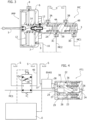
- reference 1 indicates - in its entirety - a braking system for a motor-vehicle, including four hydraulically-operated brake devices F1, F2, F3, F4, associated, respectively, with the four wheels of the vehicle.
- the brake devices F1 and F4 are associated with the two front wheels of the motor-vehicle, while the brake devices F2, F3 are associated with the two rear wheels of the motor-vehicle.
- the configuration of Figure 1 is completely independent of the type of hydraulic brake device associated with each wheel of the vehicle.
- the invention is - in fact - applicable using hydraulically-operated brake devices of any known type (for example, disc brakes or drum brakes).
- the braking system 1 comprises sub-groups 1A, 1B, 1C, 1D, 1E, 1F and an electronic controller E.
- the sub-group 1A is configured to allow a control of the contrasting force of the brake pedal actuation (feedback in force), which causes the feeling on the brake pedal, i.e., the reaction that the driver feels when he actuates the brake pedal.
- the sub-group 1B mainly comprises a master cylinder MC of any known type, intended to generate a fluid pressure following an intervention on the brake pedal.
- the sub-group 1C comprises one or more solenoid valves (in the illustrated example two solenoid valves EV1, EV2) configured to enable or disable the influence of the cylinder MC on one or more brake devices.
- solenoid valves in the illustrated example two solenoid valves EV1, EV2
- the sub-group 1D comprises one or more electrically-operated fluid pressure sources EHAS ("Electro-Hydraulic Actuation System”) designed to create fluid pressure, which adds or replaces the fluid pressure generated by the master cylinder MC to give rise to a hydraulic pressure to actuate the respective brake devices.
- EHAS Electrically-operated fluid pressure sources
- the sub-group 1E comprises a plurality of mechanical pressure transfer devices, each of which has two inlets connected, respectively, to a delivery line of the master cylinder MC and to a respective electrically-operated pressure source EHAS, to supply, accordingly, at its outlet - an actuating pressure of the respective brake device.
- the sub-group 1F consists of the group of brake devices associated with the wheels of the vehicle, which transform the hydraulic pressure supplied thereto into braking torques on the respective wheels.
- the pressure transfer devices are indicated, respectively, with PT1, PT2, PT3, PT4 in the example illustrated in Figure 1 .
- the reference S indicates a discharge and supply reservoir for the hydraulic system.
- the master cylinder MC is of the known type with two pumping pistons arranged operatively in series with each other within a casing 3 and displaceable against the action of springs 4A, 4B due to an intervention on the brake pedal P ( Figure 1 ).
- the brake pedal P is operatively connected to a rod 5, which is - in turn -operatively connected to the piston 2A.
- the inner cavity of the casing 3 communicates with the reservoir S through two inlets 3A, 3B, and also communicates with two delivery lines MC1, MC2 of the master cylinder MC through two outlets 3C, 3D.
- An intervention on the brake pedal P causes a movement of the rod 5 and, consequently, of the first piston 2A of the master cylinder MC, which is operationally connected (in the way that will be described below) to the rod 5.
- the movement of the piston 2A closes the opening 3A and pressurizes the fluid in the chamber of the master cylinder MC communicating with the delivery line MC2.
- the pressure in the chamber comprised between the two pistons 2A, 2B also determines a movement of the second piston 2B, which pressurizes the fluid in the chamber communicating with the delivery line MC1, once the piston 2B has closed the second inlet 3B.
- the predisposition of the inlet openings 3A, 3B allows the possibility of bleeding the air from the braking system, replenishing the volume of air-oil emulsion eliminated during the purging step of the hydraulic circuit with oil from the reservoir S. Furthermore, the inlet openings 3A, 3B communicating with the discharge reservoir S allow recovering the unwanted clearances that are created with the aging of the system, due to the progressive wear of the friction elements used in the brake devices (whether they are disc brakes or drum brakes).
- the sub-group 1A of the system comprises a hydraulic adjustment device of the feeling on the brake pedal, indicated with the reference PFP ("Pedal Feeling Pump").
- the PFP adjustment device comprises a hydraulic cylinder 6, with a pressure chamber 7 having an inlet 8 communicating with a discharge reservoir S, and an outlet 9 communicating with the discharge reservoir S through a line 10 in which a pressure-limiting proportional solenoid valve 11 is interposed, whose solenoid 11A is controlled by the electronic controller E, so as to regulate the passage section through the valve 11 in proportion to the electrical command sent thereto by the electronic controller E.
- a pumping member 12 is slidably mounted inside the hydraulic cylinder 6, having a central body connected on one side, by means of the rod 5, to the brake pedal, and on the other side, by means of a connecting member 13, to the first piston 2A of the master cylinder MC.
- the pumping member 12 may be pushed by the brake pedal, against the action of a spring 14, so as to pressurize the fluid in the chamber 7, since said chamber cannot freely discharge into the discharge reservoir S through the line 10, due to the resistance opposed by the passage through the proportional solenoid valve 11. Therefore, when the brake pedal is operated, it encounters a force opposing its movement, which is, for its predominant part, a function of the pressure existing in the chamber 7.
- the configuration of the PFP device is substantially similar to that adopted for the vacuum-assisted devices used in traditional braking devices.
- the chamber 7 is placed in communication with a vacuum source (for example, the intake manifold of the internal combustion engine of the vehicle) so as to generate an assistance action that helps the movement of the brake pedal.
- a vacuum source for example, the intake manifold of the internal combustion engine of the vehicle
- the chamber 7 is a chamber, which is placed at a controlled pressure, to instead generate a contrast force when the brake pedal is operated. This contrast force causes the feeling that the driver feels when operating the brake pedal.
- the electronic controller E may control the proportional solenoid valve 11, according to any predetermined program, to achieve a required load feedback on the brake pedal, regardless of the operating state of the braking system and regardless of the actuating pressure of the brake devices associated with the vehicle wheels.
- the system comprises one or more sensors 15 (schematically illustrated in Figures 1 , 2 ), which detect one or more parameters indicative of the way in which the brake pedal is actuated, such as the position, speed and acceleration of the brake pedal.
- the electronic controller E adjusts the electric current supplying the solenoid 11A of the proportional solenoid valve 11, so as to achieve the required pressure in the chamber 7 of the PFP device for regulating the feeling on the brake pedal.
- the outlet 9 of the PFP device for adjusting the feeling on the brake pedal communicates with the discharge reservoir S, also by means of a non-return valve 16, arranged in parallel with respect to the proportional solenoid valve 11, which allows a flow of fluid from the reservoir S towards the pressure chamber 7 of the PFP device, in such a way as to favor the filling of the pressure chamber 7 of the PFP device in the return phase of the movable member 12 (and of the brake pedal) towards the rest position.
- the main object of the non-return valve 16 is to:
- the PFP device is integrated into the cylinder MC and has its casing 6 rigidly connected to the casing 3 of the master cylinder MC.
- the PFP device constitutes a separate unit with respect to the master cylinder MC.
- the movable member 12 of the PFP device is, in any case, operatively connected both on one side to the brake pedal and on the other side, by means of a transmission of any type, to the piston 2A of the master cylinder MC.
- the fluid pressure transfer device The fluid pressure transfer device
- the sub-group 1E comprises, in the embodiment illustrated in Figure 1 , four fluid pressure transfer devices PT1, PT2, PT3, PT4, associated with the brake devices F1, F2, F3, F4 of the motor vehicle wheels, respectively.
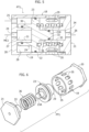
- the fluid pressure transfer device comprises a cylinder 18 defined by a casing having a cylindrical wall 19 and two end walls 20, 21.
- a movable piston member 23 is slidably mounted within the cavity of the cylindrical wall 19, with the interposition of a sealing ring 22.
- Two inlet openings 24, 25 are formed in the end wall 20 of the cylinder 18 ( Figure 5 ).
- An outlet opening 26 is formed in the end wall 21 of the cylinder 18.
- the movable piston member 23 faces a first upstream chamber 27, central, communicating with the first inlet opening 24, and a second upstream chamber 28, annular, coaxial with the first upstream chamber 27 and communicating with the second inlet opening 25.
- the two upstream chambers 27, 28 are defined by the fact that an axial tubular appendage 29 extends from the face of the movable piston member 23, facing these chambers, which is slidably mounted, with the interposition of a sealing ring 30, around an axial tubular appendage 31 protruding from the end wall 20.
- a variant would also be possible in which the tubular appendage 29 of the movable piston member 23 is arranged to slide inside the tubular appendage 31 of the end wall 20.
- the movable piston member 23 On the side facing the outlet opening 26, the movable piston member 23 has a central portion 23a of reduced diameter, which is slidably mounted, with the interposition of a sealing ring 32 within a tubular appendage 33 axially protruding from the end wall 21.
- a tubular appendage is provided, slidably mounted around the tubular appendage 33.
- a downstream chamber 34 is defined, which communicates with the outlet opening 26.
- the space between the movable piston member 23 and the end wall 21 surrounding the tubular appendage 33 is, instead, placed in communication with the atmosphere through a circumferential series of openings 35 (see also Figure 6 ). Within this space there is a helical spring 36, which tends to oppose a movement of the movable piston member 23 in the direction of the outlet opening 26.
- an EHAS Electronic-Hydraulic Actuation System
- PT1, PT2, PT3, PT4 can be, for example, constituted by an electrically-operated pump of any known type, possibly equipped with a pressurized fluid reservoir.
- Each EHAS has an inlet 37 communicating with the discharge and supply reservoir S, and an outlet 38 connected to the second inlet 25 of the respective pressure transfer device.
- Each electrically-operated fluid pressure source EHAS is controlled by the electronic controller E to provide, when activated, a fluid pressure within the second upstream chamber 28.
- Each electrically-operated fluid pressure source EHAS allows the fluid to flow freely both from the discharge and supply reservoir to the second upstream chamber 28 of the respective pressure transfer device and in a reverse flow direction, ensuring:
- each pressure transfer device communicates with a respective delivery line MC1 or MC2 of the master cylinder MC through one of the aforesaid solenoid valves EV1, EV2 for enabling or disabling the master cylinder MC.
- Each of the solenoid valves EV1, EV2 (the solenoid valve EV1 in Figure 4 ) has a first operating condition (the condition de-energized by the solenoid valve in the example illustrated) in which the solenoid valve creates a free communication passage of a delivery line of the master cylinder MC (the delivery line MC1 in Figure 4 ) with the first inlet 24 of one or more pressure transfer devices PT1, PT2, PT3, PT4.
- each delivery line MC1, MC2 of the master cylinder MC is connected to a respective solenoid valve, respectively, EV1 and EV2, and each of the two solenoid valves EV1, EV2 is connected to two pressure transfer devices, respectively, PT1, PT2 and PT3, PT4, each of which is associated with an electrically-operated fluid pressure source EHAS, and one of the brake devices F1, F2, F3, F4 of a respective wheel of the vehicle.
- the delivery line MC1 of the master cylinder MC communicates with the inlet 24 and with the first upstream chamber 27 of the pressure transfer device PT1.
- an intervention on the brake pedal causes, through the master cylinder MC, the supply of pressurized fluid into the delivery line MC1.
- the fluid pressure reaches the first upstream chamber 27 of the pressure transfer device PT1, which causes a movement of the movable piston member 23, against the action of the spring 36.
- the movement of the piston member 23 creates a transfer of pressurized fluid from the downstream chamber 34, through the outlet 26, to the hydraulic line AL for actuating one of the brake devices F1, F2, F3, F4.
- each pressure transfer device PT1-PT4 In addition to, or instead of the pressure transmitted by the master cylinder MC to the first upstream chamber 27 of each pressure transfer device PT1-PT4, it is possible to supply pressurized fluid to the second upstream chamber 28 of each pressure transfer device PT1-PT4, by activating the respective electrically-operated fluid pressure source EHAS.
- each solenoid valve EV1 when each solenoid valve EV1 is in its de-energized rest condition, in which it allows free communication between the delivery line of the master cylinder MC and the first inlet 24 of each pressure transfer device PT1-PT4, the movement of the movable piston member 23, and consequently the actuation of each brake device, may be determined either solely by the fluid pressure generated by the master cylinder, or also by the fluid pressure generated by the electrically-operated source EHAS, which in this case performs an assist function to the brake.
- the feeling on the brake pedal is controlled in a completely independent way by the electronic controller E, according to any predetermined program, by means of control of the proportional solenoid valve 11.
- the master cylinder may be excluded by moving each solenoid valve EV1 and EV2 into its second operating condition (which, in the example illustrated, is obtained by energizing the solenoid of the solenoid valve EV1, EV2).
- the connection between the delivery line MC1 or MC2 of the master cylinder MC and the first inlet 24 of each pressure transfer device PT1-PT4 is interrupted.
- each pressure transfer device PT1-PT4 is placed in communication with the discharge and supply reservoir supply S, while the delivery line MC1, MC2 of the master cylinder is placed in communication with the discharge and supply reservoir S through a restricted passage 39 ( Figure 4 ), which can be integrated into the solenoid valve EV1 or EV2 or be arranged in the line 40 that connects the corresponding outlet of the solenoid valve with the discharge reservoir.
- each solenoid valve EV1 and EV2 when each solenoid valve EV1 and EV2 is in its second operating condition, any influence of the master cylinder MC on the brake devices is canceled, and the actuation of the brake devices F1, F2, F3, F4 is solely determined by the respective electrically-operated fluid pressure sources EHAS.
- This operating mode may be controlled by the electronic controller E according to any predetermined logic. It can also be activated to obtain an ABS effect when, during braking controlled by the brake pedal, the tendency of one or more wheels of the vehicle to lock is detected, due to the reaching of the grip limit.
- the electronic controller E may detect a condition of incipient locking of a wheel following the receipt of a signal coming from one or more sensors arranged and configured to indicate this condition (for example, a sensor of the angular speed of each wheel, configured to detect a decrease in the angular velocity below a predetermined threshold). Upon the occurrence of this condition, the electronic controller E switches each solenoid valve EV1, EV2 to the operating condition of disabling the master cylinder MC, so that the first upstream chamber 27 of each pressure transfer device PT1-PT4 is discharged, while the movable piston member 23 of each pressure transfer device PT1-PT4 is controlled by the effect of the fluid pressure generated by the respective electrically-operated fluid pressure source EHAS.
- a condition of incipient locking of a wheel following the receipt of a signal coming from one or more sensors arranged and configured to indicate this condition (for example, a sensor of the angular speed of each wheel, configured to detect a decrease in the angular velocity below a predetermined threshold).
- each EHAS device is controlled in such a way as to generate a reduced fluid pressure in the actuation line AL of the brake devices F1-F4, this reduced pressure being chosen in such a way as to avoid locking of the wheel.
- the main functions of the restricted passage 39 associated with each solenoid valve EV1, EV2, are the following:
- each EHAS device allows the free passage of the fluid both from the discharge and supply reservoir towards the second upstream chamber 28 of the pressure transfer device PTi and in a reverse flow direction, guaranteeing:
- each solenoid valve for enabling/disabling the master cylinder EV1, EV2 has a third operating condition, intermediate between its first operating condition and its second operating condition, in which the solenoid valve is temporarily left open in the passage from the first operative condition to the second operative condition, and in the passage from the second operative condition to the first operative condition, so as to avoid a return pressure stroke on the brake pedal.
- the electronic controller E is configured and programmed to control the enabling/disabling solenoid valves EV1, EV2 and the electrically-operated fluid pressure sources EHAS associated with the respective pressure transfer devices PT1-PT4 and to the respective brake devices F1-F4 so as to create one or more of the operating modes described above.
- the electronic controller E may also command different operating modes of the two solenoid valves EV1, EV2 and/or of the different electrically-operated fluid pressure sources EHAS so as to command the brake devices associated with the different wheels of the vehicle in a different way, for example, to achieve a stabilizing effect by means of the Electronic Stability Control (ESC) system.
- ESC Electronic Stability Control
- FIG. 7 shows a second embodiment in which the system described above is used to control only two hydraulically-operated brake devices F1, F4 (for example, associated with the two front wheels or the two rear wheels) while the other two brake devices brake F2, F3 are electrically-operated and are controlled directly by the electronic controller E.
- each of the two delivery lines MC1, MC2 of the master cylinder MC is connected through a respective solenoid valve EV1, EV2, to a single pressure transfer device PT1 or PT2. Therefore, only two pressure transfer devices PT1, PT2 are provided, each connected to a respective electrically-operated fluid pressure source EHAS, for actuating the brake devices F1, F4, which are hydraulically-operated.
- the feeling on the brake pedal is controlled by the electronic controller E, through the adjustment device of the feeling on the pedal PFP and the associated proportional solenoid valve 11, completely independent of the actuation pressure of the brake devices.
- An important characteristic of the invention is the possibility of being used with any type of brake device, in particular, with any type of hydraulically-operated disc brake, with floating or fixed calipers, combined respectively with fixed or floating brake discs.
- the brake discs can also be of any known type, in particular also of the self-ventilating type.
- the system can also be adopted with hydraulically-operated drum brake devices.
- the system according to the invention allows the production costs of the braking system to be significantly reduced, since it can use brake devices of any known type, while being able to introduce new functions.
- the system of the invention also allows the use of safety components designed with technologies and manufactured with processes with a high level of maturity. Therefore, the possible incidence of reliability and safety problems is minimized.
- system of the invention has a wide field of application, since it allows application to any type of vehicle and to any type of wheel suspension.
Landscapes
- Engineering & Computer Science (AREA)
- Transportation (AREA)
- Mechanical Engineering (AREA)
- Physics & Mathematics (AREA)
- Fluid Mechanics (AREA)
- Electromagnetism (AREA)
- Regulating Braking Force (AREA)
- Braking Systems And Boosters (AREA)
Claims (17)
- Bremssystem für ein Kraftfahrzeug, umfassend:einen Hauptzylinder (MC), der mindestens einen Pumpkolben (2A, 2B) umfasst, der mit einem Bremspedal (P) wirkverbunden und dazu eingerichtet ist, einer Förderleitung (MC1, MC2) des Hauptzylinders (MC) im Anschluss an eine Betätigung des Bremspedals (P) Druckflüssigkeit zuzuführen, um die Aktivierung einer hydraulisch betätigten Bremsvorrichtung (F1, F2, F3, F4) zu bewirken, die mit einem jeweiligen Rad des Fahrzeugs verbunden ist,wobei das Bremssystem keine vakuumbetriebene Unterstützungsvorrichtung umfasst und wobei eine hydraulische Vorrichtung zum Anpassen des Pedalgefühls (PFP) mit dem Bremspedal (P) wirkverbunden und dazu eingerichtet ist, eine Kraft zu erzeugen und zu modulieren, die der Betätigung des Bremspedals (P) entgegenwirkt,wobei die Vorrichtung zum Anpassen des Pedalgefühls (PFP) umfasst:- einen Hydraulikzylinder (6) mit einer Druckkammer (7), die einen Einlass (8), der mit einem Ablauf- und Zulaufreservoir (S) in Verbindung steht, und einen Auslass (9) aufweist, der mit dem Ablauf- und Zulaufreservoir (S) durch ein druckbegrenzendes Proportional-Magnetventil (11) in Verbindung steht, und- ein Pumpelement (12), das in dem Hydraulikzylinder (6) bewegbar und mit dem Bremspedal (P) derart wirkverbunden ist, dass es die Flüssigkeit in der Druckkammer (7) im Anschluss an eine Betätigung des Bremspedals (P) mit Druck beaufschlagt, um die Kraft zu erzeugen, die der Betätigung des Bremspedals (P) entgegenwirkt,wobei das Bremssystem außerdem eine elektronische Steuerung (E) umfasst, die dazu eingerichtet und programmiert ist, das druckbegrenzende Proportional-Magnetventil (11), das den Auslass der Druckkammer (9) mit dem Ablauf- und Zulaufreservoir (S) verbindet, derart zu steuern, dass der Druck in der Druckkammer (7) und folglich das Gefühl am Bremspedal (P) basierend auf Signalen variiert wird, die von der elektronischen Steuerung (E) empfangen werden und einen oder mehrere Parameter angeben, die aus der Position des Bremspedals (P), der Geschwindigkeit des Bremspedals (P) und der Beschleunigung des Bremspedals (P) ausgewählt sind,wobei das Bremssystem dadurch gekennzeichnet ist, dass das Bremssystem ferner eine Druckübertragungsvorrichtung (PT1, PT2, PT3, PT4) zum Übertragen von hydraulischem Druck von der Förderleitung (MC1, MC2) des Hauptzylinders (MC) an eine hydraulische Betätigungsleitung (AL) der Bremsvorrichtung (F1, F2, F3, F4) umfasst, und dadurch, dass die Druckübertragungsvorrichtung (PT1, PT2, PT3, PT4) umfasst:- einen Zylinder (18) mit einem Element (23), das in dem Zylinder (18) zwischen einer ersten stromaufwärtigen Kammer (28), die mit der Förderleitung (MC1, MC2) des Hauptzylinders (MC) in Verbindung steht, und einer stromabwärtigen Kammer (34), die mit der hydraulischen Betätigungsleitung (AL) der Bremsvorrichtung (F1, F2, F3, F4) in Verbindung steht, derart bewegbar ist, dass der Druck, der von dem Hauptzylinder (MC) in der Förderleitung (MC1, MC2) im Anschluss an eine Einflussnahme auf das Bremspedal (P) erzeugt wird, eine Bewegung des beweglichen Elements (23) der Druckübertragungsvorrichtung (PT1, PT2, PT3, PT4) bewirkt, die einen resultierenden Druck in der hydraulischen Betätigungsleitung (AL) der Bremsvorrichtung (F1, F2, F3, F4) erzeugt,wobei die Druckübertragungsvorrichtung (PT1, PT2, PT3, PT4) außerdem eine zweite stromaufwärtige Kammer (28) umfasst, die wirkungsmäßig parallel zur ersten stromaufwärtigen Kammer (27) angeordnet ist, unddas Bremssystem außerdem eine elektrisch betätigte Flüssigkeitsdruckquelle (EHAS) umfasst, die mit der zweiten stromaufwärtigen Kammer (28) der Druckübertragungsvorrichtung (PT1, PT2, PT3, PT4) derart in Verbindung steht, dass das bewegliche Element (23) der Druckübertragungsvorrichtung (PT1, PT2, PT3, PT4) unabhängig vom Druck in der Förderleitung (MC1, MC2) des Hauptzylinders (MC) von der elektrisch betätigten Flüssigkeitsdruckquelle (EHAS) betätigt werden kann, um einen Druck in der hydraulischen Betätigungsleitung (AL) der Bremsvorrichtung (F1, F2, F3, F4) zu erzeugen.
- Bremssystem nach Anspruch 1, dadurch gekennzeichnet, dass die hydraulische Vorrichtung zum Anpassen des Pedalgefühls (PFP) in den Hauptzylinder (MC) integriert ist und ein Gehäuse (6) aufweist, das mit dem Gehäuse (3) des Hauptzylinders (MC) mit dem beweglichen Element (12) der Vorrichtung zum Anpassen des Pedalgefühls (PFP), das mit dem mindestens einen Pumpkolben (2A) des Hauptzylinders (MC) starr verbunden ist, starr verbunden ist.
- Bremssystem nach Anspruch 1, dadurch gekennzeichnet, dass die hydraulische Vorrichtung zum Anpassen des Pedalgefühls (PFP) eine vom Hauptzylinder (MC) getrennte Einheit ist und ihr bewegliches Element (12) aufweist, das mit dem mindestens einen Kolben (2A) des Hauptzylinders (MC) durch eine Übertragung wirkverbunden ist.
- Bremssystem nach Anspruch 1, dadurch gekennzeichnet, dass die hydraulische Vorrichtung zum Anpassen des Pedalgefühls (PFP) ihren Auslass (9) aufweist, der mit dem Ablauf- und Zulaufreservoir (S) auch durch ein Rückschlagventil (16) verbunden ist, das parallel zu dem vorgenannten Proportional-Magnetventil (11) angeordnet ist, um einen Fluss von dem Reservoir (S) zur Druckkammer (7) der hydraulischen Vorrichtung zum Anpassen des Pedalgefühls (PFP) derart zu ermöglichen, dass das Füllen der Druckkammer (7) der Vorrichtung erleichtert wird, wenn das bewegliche Element (12) und das Bremspedal (P) in Ruhestellungen zurückkehren.
- Bremssystem nach Anspruch 1, dadurch gekennzeichnet, dass die erste stromaufwärtige Kammer (27) und die zweite stromaufwärtige Kammer (28) der Druckübertragungsvorrichtung (PT1, PT2, PT3, PT4) koaxial zueinander umeinander angeordnet sind.
- Bremssystem nach Anspruch 5, dadurch gekennzeichnet, dass:- die Druckübertragungsvorrichtung (PT1, PT2, PT3, PT4) ein Gehäuse (18) aufweist, das einen zylindrischen Hohlraum definiert,- das bewegliche Element (23) der Druckübertragungsvorrichtung (PT1, PT2, PT3, PT4) die Form eines Kolbens hat, der verschiebbar in den zylindrischen Hohlraum eingebaut ist und eine erste Fläche, die den stromaufwärtigen Kammern (27, 28) zugewandt ist, und eine zweite Fläche aufweist, die der stromabwärtigen Kammer (34) zugewandt ist,- der Körper des Kolbens (23) der Druckübertragungsvorrichtung (PT1, PT2, PT3, PT4) einen rohrförmigen Ansatz (29) aufweist, der axial von der ersten Fläche vorsteht, wobei der Ansatz verschiebbar um oder in einen rohrförmigen Ansatz (31) montiert ist, der axial von einer ersten Stirnwand (20) des Gehäuses (18) vorsteht,derart, dass die vorgenannte erste stromaufwärtige Kammer (27) in den rohrförmigen Ansätzen (29, 31) definiert ist und mit der Förderleitung (MC1, MC2) des Hauptzylinders durch einen ersten Einlass (24) in Verbindung steht, der in der ersten Stirnwand (20) ausgebildet ist, undderart, dass die zweite stromaufwärtige Kammer (28) koaxial außerhalb der rohrförmigen Ansätze (29, 31), die miteinander in einem gleitenden Eingriff stehen, definiert ist und mit der elektrisch betätigten Flüssigkeitsdruckquelle (EHAS) durch einen zweiten Einlass (25) in Verbindung steht, der in der ersten Stirnwand (20) ausgebildet ist,und wobei ein zentraler Abschnitt mit verringertem Durchmesser (23a) axial von der zweiten Fläche des Kolbens (23) vorsteht, wobei der Abschnitt verschiebbar in oder um einen rohrförmigen Ansatz (33) montiert ist, der axial von einer zweiten Stirnwand (21) des Gehäuses (18) vorsteht,derart, dass die stromabwärtige Kammer (34) in dem rohrförmigen Ansatz (33), der von der zweiten Stirnwand (21) vorsteht, definiert ist und mit der hydraulischen Betätigungsleitung (AL) der Bremsvorrichtung (F1, F2, F3, F4) durch einen Auslass (26) in Verbindung steht, der in der zweiten Stirnwand (21) ausgebildet ist,und wobei koaxial außerhalb des rohrförmigen Ansatzes (33), der von der zweiten Stirnwand (21) vorsteht, eine mit der Atmosphäre in Verbindung stehende Kammer definiert ist, in der eine Schraubenfeder (33) angeordnet ist, die darauf gerichtet ist, den Kolben (23) in Richtung der stromaufwärtigen Kammern (27, 28) zu drücken.
- Bremssystem nach Anspruch 1, dadurch gekennzeichnet, dass in der Förderleitung (MC1, MC2) des Hauptzylinders (MC) zwischen den Auslass (3C, 3D) des Hauptzylinders (MC) und die erste stromaufwärtige Kammer (27) der Druckübertragungsvorrichtung (PT1, PT2, PT3, PT4) ein Magnetventil (EV1, EV2) zum Freigeben/Sperren des Hauptzylinders zwischengeschaltet ist, das einen ersten Betriebszustand, in dem es den Auslass (3C, 3D) des Hauptzylinders (MC) mit der ersten stromaufwärtigen Kammer (27) der Druckübertragungsvorrichtung (PT1, PT2, PT3, PT4) in Verbindung setzt, und einen zweiten Betriebszustand aufweist, in dem die erste stromaufwärtige Kammer (27) der Druckübertragungsvorrichtung (PT1, PT2, PT3, PT4) mit dem Ablauf- und Zulaufreservoir (S) in Verbindung gesetzt ist und in dem der Auslass (3C, 3D) des Hauptzylinders (MC) mit dem Ablauf- und Zulaufreservoir (S) durch einen verengten Durchgang (39) in Verbindung gesetzt ist.
- Bremssystem nach Anspruch 7, dadurch gekennzeichnet, dass sich das Magnetventil (EV1, EV2) zum Freigeben/Sperren des Hauptzylinders in dem ersten Betriebszustand befindet, wenn es stromlos ist, und sich in dem zweiten Betriebszustand befindet, wenn es bestromt ist.
- Bremssystem nach Anspruch 7, dadurch gekennzeichnet, dass das Magnetventil (EV1, EV2) zum Freigeben/Sperren des Hauptzylinders (MC) einen dritten Betriebszustand zwischen seinem ersten Betriebszustand und seinem zweiten Betriebszustand aufweist, in dem das Magnetventil vorübergehend offen gelassen wird, wenn ein Übergang vom ersten Betriebszustand in den zweiten Betriebszustand oder umgekehrt befohlen wird, um einen Rückdruckschlag auf das Bremspedal (P) zu vermeiden.
- Bremssystem nach Anspruch 7, dadurch gekennzeichnet, dass die elektronische Steuerung (E) dazu eingerichtet und programmiert ist, das Magnetventil (EV1, EV2) zum Freigeben/Sperren des Hauptzylinders und die elektrisch betätigte Flüssigkeitsdruckquelle (EHAS) derart zu steuern, dass einer oder mehrere der folgenden Betriebsmodi selektiv aktiviert werden können:- einen Basisbremsbetriebsmodus, in dem sich das Magnetventil (EV1, EV2) zum Freigeben/Sperren des Hauptzylinders (MC) in seinem ersten Betriebszustand befindet und den Hauptzylinder (MC) freigibt und die elektrisch betätigte Flüssigkeitsdruckquelle (EHAS) inaktiv ist, sodass die Bremsvorrichtung (F1, F2, F3, F4) durch das Bremspedal (P) mittels des Hauptzylinders (MC) betätigt wird,- einen Betriebsmodus für das unterstützte Bremsen, in dem sich das Magnetventil (EV1, EV2) zum Freigeben/Sperren des Hauptzylinders (MC) in seinem ersten Betriebszustand befindet und den Hauptzylinder (MC) freigibt und die elektrisch betätigte Flüssigkeitsdruckquelle (EHAS) aktiv ist, sodass die Bremsvorrichtung (F1, F2, F3, F4) durch das Bremspedal (P) mittels des Hauptzylinders (MC) betätigt wird, aber der der Bremsvorrichtung (F1, F2, F3, F4) zugeführte Flüssigkeitsdruck das Ergebnis sowohl des von dem Hauptzylinder (MC) erzeugten Drucks als auch des von der elektrisch betätigten Flüssigkeitsdruckquelle (EHAS) erzeugten Drucks ist,- einen automatischen Bremsbetriebsmodus, in dem sich das Magnetventil (EV1, EV2) zum Freigeben/Sperren des Hauptzylinders (MC) in seinem zweiten Betriebszustand befindet und den Hauptzylinder sperrt und die elektrisch betätigte Flüssigkeitsdruckquelle (EHAS) aktiv ist, sodass die Bremsvorrichtung (F1, F2, F3, F4) nur durch den von der elektrisch betätigten Flüssigkeitsdruckquelle (EHAS) erzeugten Druck betätigt wird, und- einen Betriebsmodus zum Aktivieren einer ABS-Wirkung, in dem im Anschluss an die Erfassung durch die elektronische Steuerung (E) eines Zustands des beginnenden Blockierens des Fahrzeugsrads während einer vom Bremspedal (P) durch den Hauptzylinder (MC) oder automatisch gesteuerten Bremsung das Magnetventil (EV1, EV2) zum Freigeben/Sperren des Hauptzylinders (MC) von seinem ersten Betriebszustand zum Freigeben in seinen zweiten Betriebszustand zum Sperren des Hauptzylinders umgeschaltet wird und die elektrisch betätigte Flüssigkeitsdruckquelle (EHAS) aktiviert wird, um einen reduzierten Druck in der Versorgungsleitung (AL) der Bremsvorrichtung (F1, F2, F3, F4) zu erzeugen, um ein Blockieren des Rads während einer Bremsung zu vermeiden.
- Bremssystem nach einem der vorhergehenden Ansprüche, dadurch gekennzeichnet, dass der Hauptzylinder (MC) mindestens zwei Pumpkolben (2A, 2B) umfasst, die wirkungsmäßig miteinander in Reihe angeordnet und dazu eingerichtet sind, mindestens zwei Förderleitungen (MC1, MC2) des Hauptzylinders (MC) im Anschluss an eine Betätigung des Bremspedals (P) mit Druckflüssigkeit zu versorgen,dadurch, dass ein jeweiliges Magnetventil (EV1, EV2) zum Freigeben/Sperren des Hauptzylinders (MC) in jede der mindestens zwei Förderleitungen (MC1, MC2) des Hauptzylinders (MC) eingefügt ist, wobei dieses Magnetventil die Verbindung zwischen einem jeweiligen Auslass (3C, 3D) des Hauptzylinders (MC) und einer oder mehreren Druckübertragungsvorrichtungen (PT1, PT2, PT3, PT4) steuert,dadurch, dass jede der Druckübertragungsvorrichtungen (PT1, PT2, PT3, PT4) außerdem mit einer jeweiligen elektrisch betätigte Flüssigkeitsdruckquelle (EHAS) verbunden und dazu eingerichtet ist, Flüssigkeitsdruck in der hydraulischen Betätigungsleitung (AL) einer jeweiligen Bremsvorrichtung (F1, F2, F3, F4) zu erzeugen.
- Bremssystem nach Anspruch 11, dadurch gekennzeichnet, dass jede der zwei Förderleitungen (MC1, MC2) des Hauptzylinders (MC) zwei mit zwei Rädern des Fahrzeugs verbundene Bremsvorrichtungen (F1, F2; F3, F4) durch ein jeweiliges Freigabe-/Sperr-Magnetventil (EV1, EV2) steuert, das mit zwei Druckübertragungsvorrichtungen (PT1, PT2; PT3, PT4) verbunden ist, die den Flüssigkeitsdruck in den Betätigungsleitungen (AL) der zwei Bremsvorrichtungen (F1, F2; F3, F4) steuern und die außerdem mit einer jeweiligen elektrisch betätigten Flüssigkeitsdruckquelle (EHAS) verbunden sind.
- Bremssystem nach Anspruch 11, dadurch gekennzeichnet, dass jede der zwei Förderleitungen (MC1, MC2) des Hauptzylinders (MC) nur eine jeweilige mit einem Rad des Fahrzeugs verbundene Bremsvorrichtung (F1, F4) mittels eines Freigabe-/Sperr-Magnetventils (EV1, EV2) steuert, das mit einer Druckübertragungsvorrichtung (PT1, PT2) verbunden ist, die den Flüssigkeitsdruck in der Betätigungsleitung (AL) der jeweiligen Bremsvorrichtung (F1, F4) steuert, und die außerdem mit einer jeweiligen elektrisch betätigten Flüssigkeitsdruckquelle (EHAS) verbunden ist,
wobei das Bremssystem außerdem zwei mit zwei zusätzlichen Rädern des Fahrzeugs verbundene elektrisch betätigte Bremsvorrichtungen (F2, F3) umfasst, die von der elektronischen Steuerung (E) gesteuert werden. - Verfahren zum Steuern eines Bremssystems eines Fahrzeugs nach Anspruch 1, wobei das Bremssystem einen Hauptzylinder (MC) umfasst, der mindestens einen Pumpkolben (2A, 2B) umfasst, der mit einem Bremspedal (P) wirkverbunden und dazu eingerichtet ist, im Anschluss an eine Betätigung des Bremspedals (P) Druckflüssigkeit in eine Förderleitung (MC1, MC2) des Hauptzylinders (MC) einzuleiten, um die Aktivierung einer hydraulisch betätigten Bremsvorrichtung (F1, F2, F3, F4) zu bewirken, die mit einem jeweiligen Rad des Fahrzeugs verbunden ist,wobei dieses Verfahren dadurch gekennzeichnet ist, dass:- eine Druckübertragungsvorrichtung (PT1, PT2, PT3, PT4) dazu eingerichtet ist, hydraulischen Druck von der Förderleitung (MC1, MC2) des Hauptzylinders (MC) an eine hydraulische Betätigungsleitung (AL) der Bremsvorrichtung (F1, F2, F3, F4) zu übertragen, wobei die Druckübertragungsvorrichtung (PT1, PT2, PT3, PT4) umfasst:- einen Zylinder (18) mit einem beweglichen Element (23) in dem Zylinder zwischen einer ersten stromaufwärtigen Kammer (27), die mit der Förderleitung (MC1, MC2) des Hauptzylinders (MC) in Verbindung steht, und einer stromabwärtigen Kammer (34), die mit der hydraulischen Betätigungsleitung (AL) der Bremsvorrichtung (F1, F2, F3, F4) in Verbindung steht, sodass der Druck, der von dem Hauptzylinder (MC) in der Förderleitung (MC1, MC2) im Anschluss an eine Einflussnahme auf das Bremspedal (P) erzeugt wird, eine Bewegung des beweglichen Elements (23) der Druckübertragungsvorrichtung (PT1, PT2, PT3, PT4) bewirkt, die einen resultierenden Druck in der hydraulischen Betätigungsleitung (AL) der Bremsvorrichtung (F1, F2, F3, F4) erzeugt,- die Druckübertragungsvorrichtung (PT1, PT2, PT3, PT4) außerdem eine zweite stromaufwärtige Kammer (28) umfasst, die wirkungsmäßig parallel zur ersten stromaufwärtigen Kammer (27) angeordnet ist,- eine elektrisch betätigte Flüssigkeitsdruckquelle (EHAS) in Verbindung mit der zweiten stromaufwärtigen Kammer (28) der Druckübertragungsvorrichtung (PT1, PT2, PT3, PT4) angeordnet ist,derart, dass das bewegliche Element (23) der Druckübertragungsvorrichtung (PT1, PT2, PT3, PT4) unabhängig vom Druck in der Förderleitung (MC1, MC2) des Hauptzylinders (MC) durch die elektrisch betätigte Flüssigkeitsdruckquelle (EHAS) betätigt werden kann, um einen Druck in der hydraulischen Betätigungsleitung (AL) der Bremsvorrichtung zu erzeugen,- ein Magnetventil (EV1, EV2) zum Freigeben/Sperren des Hauptzylinders (MC) in der Förderleitung (MC1, MC2) des Hauptzylinders (MC) zwischen dem Auslass (3C, 3D) des Hauptzylinders (MC) und der ersten stromaufwärtigen Kammer (27) der Druckübertragungsvorrichtung (PT1, PT2, PT3, PT4) angeordnet ist, wobei das Magnetventil (EV1, EV2) zum Freigeben/Sperren des Hauptzylinders (MC) einen ersten Betriebszustand, in dem es den Auslass (3C, 3D) des Hauptzylinders (MC) mit der ersten stromaufwärtigen Kammer (27) der Druckübertragungsvorrichtung (PT1, PT2, PT3, PT4) in Verbindung setzt, und einen zweiten Betriebszustand aufweist, in dem die erste stromaufwärtige Kammer (27) der Druckübertragungsvorrichtung (PT1, PT2, PT3, PT4) mit dem Ablauf- und Zulaufreservoir (S) in Verbindung gesetzt ist und in dem der Auslass (3C, 3D) des Hauptzylinders (MC) mit dem Ablaufreservoir (S) durch einen verengten Durchgang (39) in Verbindung gesetzt ist,- wobei das Magnetventil (EV1, EV2) zum Freigeben/Sperren des Hauptzylinders und die elektrisch betätigte Flüssigkeitsdruckquelle (EHAS) von einer elektronischen Steuerung (E) derart gesteuert werden, dass einer oder mehrere der folgenden Betriebsmodi selektiv gesteuert werden können:- einen Basisbremsbetriebsmodus, in dem sich das Magnetventil (EV1, EV2) zum Freigeben/Sperren des Hauptzylinders (MC) in seinem ersten Betriebszustand befindet und den Hauptzylinder (MC) freigibt und die elektrisch betätigte Flüssigkeitsdruckquelle (EHAS) inaktiv ist, sodass die Bremsvorrichtung (F1, F2, F3, F4) durch das Bremspedal (P) mittels des Hauptzylinders (MC) betätigt wird,- einen Betriebsmodus für das unterstützte Bremsen, in dem sich das Magnetventil (EV1, EV2) zum Freigeben/Sperren des Hauptzylinders (MC) in seinem ersten Betriebszustand befindet und den Hauptzylinder (MC) freigibt und die elektrisch betätigte Flüssigkeitsdruckquelle (EHAS) aktiv ist, sodass die Bremsvorrichtung (F1, F2, F3, F4) durch das Bremspedal (P) mittels des Hauptzylinders betätigt wird, aber der der Bremsvorrichtung (F1, F2, F3, F4) zugeführte Flüssigkeitsdruck das Ergebnis sowohl des von dem Hauptzylinder erzeugten Drucks als auch des von der elektrisch betätigten Flüssigkeitsdruckquelle (EHAS) erzeugten Drucks ist,- einen automatischen Bremsbetriebsmodus, in dem sich das Magnetventil (EV1, EV2) zum Freigeben/Sperren des Hauptzylinders (MC) in seinem zweiten Betriebszustand befindet und den Hauptzylinder sperrt und die elektrisch betätigte Flüssigkeitsdruckquelle (EHAS) aktiv ist, sodass die Bremsvorrichtung (F1, F2, F3, F4) nur durch den von der elektrisch betätigten Flüssigkeitsdruckquelle (EHAS) erzeugten Druck betätigt wird, und- einen Betriebsmodus zum Aktivieren einer ABS-Wirkung, in dem im Anschluss an die Erfassung durch die elektronische Steuerung (E) eines Zustands des beginnenden Blockierens eines Fahrzeugsrads während einer vom Bremspedal (P) durch den Hauptzylinder (MC) oder automatisch gesteuerten Bremsung das Magnetventil (EV1, EV2) zum Freigeben/Sperren des Hauptzylinders (MC) von seinem ersten Betriebszustand zum Freigeben in seinen zweiten Betriebszustand zum Sperren des Hauptzylinders (MC) umgeschaltet wird und die elektrisch betätigte Flüssigkeitsdruckquelle (EHAS) aktiviert wird, um einen reduzierten Druck in der Versorgungsleitung (AL) der Bremsvorrichtung (F1, F2, F3, F4) zu erzeugen, um ein Blockieren des Rads während einer Bremsung zu vermeiden.
- Steuerungsverfahren nach Anspruch 14, wobei das Bremssystem ferner eine mit dem Bremspedal (P) verbundene hydraulische Vorrichtung zum Anpassen des Pedalgefühls (PFP) umfasst, die dazu eingerichtet ist, eine Kraft zu erzeugen und zu modulieren, die der Betätigung des Bremspedals (P) entgegenwirkt, wobei die Vorrichtung zum Anpassen des Pedalgefühls (PFP) umfasst:- einen Hydraulikzylinder (6) mit einer Druckkammer (7), die einen Einlass (8), der mit einem Ablauf- und Zulaufreservoir (S) in Verbindung steht, und einen Auslass (9) aufweist, der mit dem Ablauf- und Zulaufreservoir (S) durch ein druckbegrenzendes Proportional-Magnetventil (11) in Verbindung steht, und- ein Pumpelement (12), das in dem Hydraulikzylinder (6) bewegbar und mit dem Bremspedal (P) derart wirkverbunden ist, dass es die Flüssigkeit in der Druckkammer (7) im Anschluss an eine Betätigung des Bremspedals (P) mit Druck beaufschlagt, um die vorgenannte Kraft zu erzeugen, die der Betätigung des Bremspedals (P) entgegenwirkt,wobei das Verfahren dadurch gekennzeichnet ist, dass es den Schritt des Steuerns mittels der elektronischen Steuerung (E) des druckbegrenzenden Proportional-Magnetventils (11) derart umfasst, dass das Gefühl am Bremspedal (P) unabhängig von dem von der Bremsvorrichtung (F1, F2, F3, F4) gelieferten Flüssigkeitsdruck auf der Grundlage von Signalen variiert wird, die von der elektronischen Steuerung (E) empfangen werden und einen oder mehrere Parameter angeben, die aus der Position des Bremspedals (P), der Geschwindigkeit des Bremspedals (P) und der Beschleunigung des Bremspedals (P) ausgewählt sind.
- Steuerungsverfahren nach Anspruch 14, wobei der Hauptzylinder (MC) mindestens zwei Pumpkolben (2A, 2B) umfasst, die wirkungsmäßig miteinander in Reihe angeordnet und dazu eingerichtet sind, mindestens zwei Förderleitungen (MC1, MC2) des Hauptzylinders (MC) im Anschluss an eine Betätigung des Bremspedals (P) Druckflüssigkeit zuzuführen, wobei ein jeweiliges Magnetventil (EV1, EV2) zum Freigeben/Sperren des Hauptzylinders (MC) in jede der mindestens zwei Förderleitungen (MC1, MC2) des Hauptzylinders (MC) eingefügt ist, das die Verbindung zwischen einem jeweiligen Auslass (3C, 3D) des Hauptzylinders (MC) und einer oder mehreren Druckübertragungsvorrichtungen (PT1, PT2, PT3, PT4) steuert, mit einer jeweiligen elektrisch betätigten Flüssigkeitsdruckquelle (EHAS) verbunden ist und darauf ausgelegt ist, Flüssigkeitsdruck in der hydraulischen Betätigungsleitung (AL) einer jeweiligen Bremsvorrichtung (F1, F2, F3, F4) zu erzeugen,
wobei das Verfahren dadurch gekennzeichnet ist, dass die Magnetventile (EV1, EV2) zum Freigeben/Sperren des Hauptzylinders (MC), die mit den zwei Förderleitungen (MC1, MC2) des Hauptzylinders (MC) und den vorgenannten, mit jeweiligen Druckübertragungsvorrichtungen (PT1, PT2, PT3, PT4) und jeweiligen Bremsvorrichtungen (F1, F2, F3, F4) verbundenen elektrisch betätigten Flüssigkeitsdruckquellen (EHAS) verbunden sind, mittels der elektronischen Steuerung (E) entweder in identischer oder in differenzierter Weise gesteuert werden, um in Abhängigkeit von den Betriebsbedingungen jedes Rads, von jeglicher Neigung jedes Rads, während einer Bremsung zu blockieren, und von der Notwendigkeit, eine etwaige Fahrinstabilität des Fahrzeugs zu korrigieren, entweder identische oder differenzierte Bremswirkungen an den verschiedenen Rädern des Fahrzeugs zu erhalten. - Verfahren nach Anspruch 16, wobei das Bremssystem zwei hydraulisch betätigte Bremsvorrichtungen (F1, F4) steuert, die mit zwei Rädern des Fahrzeugs verbunden sind, während die anderen zwei Räder des Fahrzeugs mit elektrisch betätigten Bremsvorrichtungen (F2, F3) versehen sind, wobei das Verfahren dadurch gekennzeichnet ist, dass die Betätigung der elektrisch betätigten Bremsvorrichtungen (F2, F3) mittels der elektronischen Steuerung (E) auf der Grundlage von Signalen, die einen oder mehrere Parameter angeben, die aus der Position des Bremspedals (P), der Geschwindigkeit des Bremspedals (P) und der Beschleunigung des Bremspedals (P) ausgewählt sind, und in Abhängigkeit von jeglicher Neigung der mit den elektrisch betätigten Bremsvorrichtungen (F2, F3) verbundenen Räder, während einer Bremsung zu blockieren, und in Abhängigkeit von jeglicher Notwendigkeit, eine beginnende Fahrinstabilität des Fahrzeugs zu korrigieren, gesteuert wird.
Priority Applications (4)
| Application Number | Priority Date | Filing Date | Title |
|---|---|---|---|
| EP21175737.2A EP4095005B1 (de) | 2021-05-25 | 2021-05-25 | Bremssystem für ein fahrzeug |
| BR102022009182-0A BR102022009182A2 (pt) | 2021-05-25 | 2022-05-11 | Sistema de frenagem de veículo |
| US17/664,716 US12370986B2 (en) | 2021-05-25 | 2022-05-24 | Vehicle braking system |
| CN202210576524.XA CN115384466A (zh) | 2021-05-25 | 2022-05-25 | 车辆制动系统 |
Applications Claiming Priority (1)
| Application Number | Priority Date | Filing Date | Title |
|---|---|---|---|
| EP21175737.2A EP4095005B1 (de) | 2021-05-25 | 2021-05-25 | Bremssystem für ein fahrzeug |
Publications (2)
| Publication Number | Publication Date |
|---|---|
| EP4095005A1 EP4095005A1 (de) | 2022-11-30 |
| EP4095005B1 true EP4095005B1 (de) | 2024-09-11 |
Family
ID=76859395
Family Applications (1)
| Application Number | Title | Priority Date | Filing Date |
|---|---|---|---|
| EP21175737.2A Active EP4095005B1 (de) | 2021-05-25 | 2021-05-25 | Bremssystem für ein fahrzeug |
Country Status (4)
| Country | Link |
|---|---|
| US (1) | US12370986B2 (de) |
| EP (1) | EP4095005B1 (de) |
| CN (1) | CN115384466A (de) |
| BR (1) | BR102022009182A2 (de) |
Families Citing this family (4)
| Publication number | Priority date | Publication date | Assignee | Title |
|---|---|---|---|---|
| DE102018206566A1 (de) * | 2018-04-27 | 2019-10-31 | Robert Bosch Gmbh | Fahrzeugbremssystem und Verfahren zur Bremsdrucksteigerung in einem ersten Radbremszylinder und Bremsdruckbegrenzung in einem zweiten Radbremszylinder eines Fahrzeugbremssystems |
| US12227159B2 (en) | 2021-08-12 | 2025-02-18 | ZF Active Safety US Inc. | Fluid separator and brake systems using same |
| CN116923341B (zh) * | 2023-07-17 | 2026-03-17 | 北京经纬恒润科技股份有限公司 | 压力确定方法及装置 |
| CN118701016A (zh) * | 2024-07-22 | 2024-09-27 | 上海拿森汽车电子有限公司 | 一种电子制动系统 |
Family Cites Families (15)
| Publication number | Priority date | Publication date | Assignee | Title |
|---|---|---|---|---|
| DE3010639A1 (de) * | 1980-03-20 | 1981-09-24 | Alfred Teves Gmbh, 6000 Frankfurt | Hydraulisches bremssystem mit einer antiblockierregelanlage |
| US4755008A (en) * | 1985-12-25 | 1988-07-05 | Nippondenso Co., Ltd. | Braking system with power brake, braking force proportioning, anti-skid, and traction control functions |
| DE4108756A1 (de) * | 1990-10-05 | 1992-09-24 | Teves Gmbh Alfred | Kraftfahrzeugbremsanlage mit schlupfabhaengiger regelung des bremsdruckes |
| WO1997037878A1 (en) * | 1996-04-09 | 1997-10-16 | Kelsey Hayes Company | Vehicle hydraulic braking systems incorporating volume-variant actuators |
| JP2000177562A (ja) * | 1998-12-15 | 2000-06-27 | Akebono Brake Ind Co Ltd | ブレーキ液圧制御装置 |
| US8328297B2 (en) * | 2006-06-06 | 2012-12-11 | Honda Motor Co., Ltd. | Brake system |
| JP4733754B2 (ja) * | 2008-10-08 | 2011-07-27 | 本田技研工業株式会社 | 車両用ブレーキ装置における引きずり防止方法 |
| US9340193B2 (en) * | 2009-02-03 | 2016-05-17 | Kelsey-Hayes Company | Vehicle brake system |
| US8651587B2 (en) * | 2011-03-10 | 2014-02-18 | Continental Automotive Systems, Inc. | Electronically controlled hydraulic brake system |
| JP5819359B2 (ja) * | 2013-07-16 | 2015-11-24 | 本田技研工業株式会社 | 電動ブレーキ装置 |
| DE102015212552A1 (de) * | 2014-07-21 | 2016-01-21 | Continental Teves Ag & Co. Ohg | Anordnung für eine hydraulische Kraftfahrzeug-Bremsanlage sowie Bremsanlage mit einer solchen Anordnung |
| DE102014225954A1 (de) * | 2014-12-16 | 2016-06-16 | Continental Teves Ag & Co. Ohg | Bremsensteuervorrichtung sowie Bremsanlage |
| DE102016203111A1 (de) * | 2015-03-05 | 2016-09-08 | Continental Teves Ag & Co. Ohg | Bremsanlage für Kraftfahrzeuge |
| US20210155215A1 (en) * | 2018-04-04 | 2021-05-27 | ZF Active Safety US Inc. | Vehicle brake system with secondary brake module |
| KR20190136207A (ko) * | 2018-05-30 | 2019-12-10 | 주식회사 만도 | 전자식 브레이크 시스템 |
-
2021
- 2021-05-25 EP EP21175737.2A patent/EP4095005B1/de active Active
-
2022
- 2022-05-11 BR BR102022009182-0A patent/BR102022009182A2/pt unknown
- 2022-05-24 US US17/664,716 patent/US12370986B2/en active Active
- 2022-05-25 CN CN202210576524.XA patent/CN115384466A/zh active Pending
Also Published As
| Publication number | Publication date |
|---|---|
| US12370986B2 (en) | 2025-07-29 |
| CN115384466A (zh) | 2022-11-25 |
| US20220379859A1 (en) | 2022-12-01 |
| BR102022009182A2 (pt) | 2022-12-06 |
| EP4095005A1 (de) | 2022-11-30 |
Similar Documents
| Publication | Publication Date | Title |
|---|---|---|
| US12370986B2 (en) | Vehicle braking system | |
| JP5841455B2 (ja) | ブレーキ装置 | |
| US9428168B2 (en) | Brake device | |
| JP5096593B2 (ja) | ブレーキ装置 | |
| US7267411B2 (en) | Brake system for a motorcycle, and method of using same | |
| US5236257A (en) | Brake pressure generator having means for controlling pressure independent of operation of brake operating member | |
| US10336304B2 (en) | Brake system for vehicle | |
| JPS6320256A (ja) | マニユアル・電気二系統ブレ−キ装置 | |
| JP2000203413A (ja) | 液圧ブレ―キ装置 | |
| US5161865A (en) | Hydraulic modulator with working piston connected to control piston | |
| JP6371271B2 (ja) | 車両用制動装置 | |
| CN117580743A (zh) | 制动系统及用于操作该制动系统的方法 | |
| JP6245696B2 (ja) | ブレーキ液圧発生装置 | |
| US11767001B2 (en) | Method for operating a brake system, and brake system | |
| JP2511609B2 (ja) | リニア可変圧力適応ブレ―キ/トラクション制御装置 | |
| JP7813959B2 (ja) | 車両用ブレーキシステム | |
| JP7838439B2 (ja) | 制動装置 | |
| JP6317659B2 (ja) | 車両用ブレーキシステム | |
| JP7438341B2 (ja) | 特に自動車のための電子的にスリップ制御可能な非人力ブレーキシステムを制御する方法、および特に自動車のための電子的にスリップ制御可能な非人力ブレーキシステム | |
| JP7658139B2 (ja) | 車両用制動装置 | |
| US7475952B2 (en) | Braking system with mechanical combination valves | |
| JP5006243B2 (ja) | ブレーキ制御装置 | |
| JP7552344B2 (ja) | 車両用制動装置 | |
| JP2006160085A (ja) | ブレーキ制御装置 | |
| JP7121677B2 (ja) | ブレーキ制御装置 |
Legal Events
| Date | Code | Title | Description |
|---|---|---|---|
| PUAI | Public reference made under article 153(3) epc to a published international application that has entered the european phase |
Free format text: ORIGINAL CODE: 0009012 |
|
| STAA | Information on the status of an ep patent application or granted ep patent |
Free format text: STATUS: REQUEST FOR EXAMINATION WAS MADE |
|
| 17P | Request for examination filed |
Effective date: 20220329 |
|
| AK | Designated contracting states |
Kind code of ref document: A1 Designated state(s): AL AT BE BG CH CY CZ DE DK EE ES FI FR GB GR HR HU IE IS IT LI LT LU LV MC MK MT NL NO PL PT RO RS SE SI SK SM TR |
|
| STAA | Information on the status of an ep patent application or granted ep patent |
Free format text: STATUS: EXAMINATION IS IN PROGRESS |
|
| 17Q | First examination report despatched |
Effective date: 20230525 |
|
| GRAP | Despatch of communication of intention to grant a patent |
Free format text: ORIGINAL CODE: EPIDOSNIGR1 |
|
| STAA | Information on the status of an ep patent application or granted ep patent |
Free format text: STATUS: GRANT OF PATENT IS INTENDED |
|
| INTG | Intention to grant announced |
Effective date: 20240430 |
|
| GRAS | Grant fee paid |
Free format text: ORIGINAL CODE: EPIDOSNIGR3 |
|
| GRAA | (expected) grant |
Free format text: ORIGINAL CODE: 0009210 |
|
| STAA | Information on the status of an ep patent application or granted ep patent |
Free format text: STATUS: THE PATENT HAS BEEN GRANTED |
|
| AK | Designated contracting states |
Kind code of ref document: B1 Designated state(s): AL AT BE BG CH CY CZ DE DK EE ES FI FR GB GR HR HU IE IS IT LI LT LU LV MC MK MT NL NO PL PT RO RS SE SI SK SM TR |
|
| REG | Reference to a national code |
Ref country code: GB Ref legal event code: FG4D |
|
| REG | Reference to a national code |
Ref country code: CH Ref legal event code: EP |
|
| REG | Reference to a national code |
Ref country code: DE Ref legal event code: R096 Ref document number: 602021018537 Country of ref document: DE |
|
| REG | Reference to a national code |
Ref country code: IE Ref legal event code: FG4D |
|
| REG | Reference to a national code |
Ref country code: LT Ref legal event code: MG9D |
|
| PG25 | Lapsed in a contracting state [announced via postgrant information from national office to epo] |
Ref country code: NO Free format text: LAPSE BECAUSE OF FAILURE TO SUBMIT A TRANSLATION OF THE DESCRIPTION OR TO PAY THE FEE WITHIN THE PRESCRIBED TIME-LIMIT Effective date: 20241211 |
|
| REG | Reference to a national code |
Ref country code: NL Ref legal event code: MP Effective date: 20240911 |
|
| PG25 | Lapsed in a contracting state [announced via postgrant information from national office to epo] |
Ref country code: GR Free format text: LAPSE BECAUSE OF FAILURE TO SUBMIT A TRANSLATION OF THE DESCRIPTION OR TO PAY THE FEE WITHIN THE PRESCRIBED TIME-LIMIT Effective date: 20241212 Ref country code: FI Free format text: LAPSE BECAUSE OF FAILURE TO SUBMIT A TRANSLATION OF THE DESCRIPTION OR TO PAY THE FEE WITHIN THE PRESCRIBED TIME-LIMIT Effective date: 20240911 |
|
| PG25 | Lapsed in a contracting state [announced via postgrant information from national office to epo] |
Ref country code: BG Free format text: LAPSE BECAUSE OF FAILURE TO SUBMIT A TRANSLATION OF THE DESCRIPTION OR TO PAY THE FEE WITHIN THE PRESCRIBED TIME-LIMIT Effective date: 20240911 |
|
| PG25 | Lapsed in a contracting state [announced via postgrant information from national office to epo] |
Ref country code: LV Free format text: LAPSE BECAUSE OF FAILURE TO SUBMIT A TRANSLATION OF THE DESCRIPTION OR TO PAY THE FEE WITHIN THE PRESCRIBED TIME-LIMIT Effective date: 20240911 |
|
| PG25 | Lapsed in a contracting state [announced via postgrant information from national office to epo] |
Ref country code: HR Free format text: LAPSE BECAUSE OF FAILURE TO SUBMIT A TRANSLATION OF THE DESCRIPTION OR TO PAY THE FEE WITHIN THE PRESCRIBED TIME-LIMIT Effective date: 20240911 |
|
| PG25 | Lapsed in a contracting state [announced via postgrant information from national office to epo] |
Ref country code: RS Free format text: LAPSE BECAUSE OF FAILURE TO SUBMIT A TRANSLATION OF THE DESCRIPTION OR TO PAY THE FEE WITHIN THE PRESCRIBED TIME-LIMIT Effective date: 20241211 Ref country code: ES Free format text: LAPSE BECAUSE OF FAILURE TO SUBMIT A TRANSLATION OF THE DESCRIPTION OR TO PAY THE FEE WITHIN THE PRESCRIBED TIME-LIMIT Effective date: 20240911 |
|
| PG25 | Lapsed in a contracting state [announced via postgrant information from national office to epo] |
Ref country code: RS Free format text: LAPSE BECAUSE OF FAILURE TO SUBMIT A TRANSLATION OF THE DESCRIPTION OR TO PAY THE FEE WITHIN THE PRESCRIBED TIME-LIMIT Effective date: 20241211 Ref country code: NO Free format text: LAPSE BECAUSE OF FAILURE TO SUBMIT A TRANSLATION OF THE DESCRIPTION OR TO PAY THE FEE WITHIN THE PRESCRIBED TIME-LIMIT Effective date: 20241211 Ref country code: LV Free format text: LAPSE BECAUSE OF FAILURE TO SUBMIT A TRANSLATION OF THE DESCRIPTION OR TO PAY THE FEE WITHIN THE PRESCRIBED TIME-LIMIT Effective date: 20240911 Ref country code: HR Free format text: LAPSE BECAUSE OF FAILURE TO SUBMIT A TRANSLATION OF THE DESCRIPTION OR TO PAY THE FEE WITHIN THE PRESCRIBED TIME-LIMIT Effective date: 20240911 Ref country code: GR Free format text: LAPSE BECAUSE OF FAILURE TO SUBMIT A TRANSLATION OF THE DESCRIPTION OR TO PAY THE FEE WITHIN THE PRESCRIBED TIME-LIMIT Effective date: 20241212 Ref country code: FI Free format text: LAPSE BECAUSE OF FAILURE TO SUBMIT A TRANSLATION OF THE DESCRIPTION OR TO PAY THE FEE WITHIN THE PRESCRIBED TIME-LIMIT Effective date: 20240911 Ref country code: ES Free format text: LAPSE BECAUSE OF FAILURE TO SUBMIT A TRANSLATION OF THE DESCRIPTION OR TO PAY THE FEE WITHIN THE PRESCRIBED TIME-LIMIT Effective date: 20240911 Ref country code: BG Free format text: LAPSE BECAUSE OF FAILURE TO SUBMIT A TRANSLATION OF THE DESCRIPTION OR TO PAY THE FEE WITHIN THE PRESCRIBED TIME-LIMIT Effective date: 20240911 |
|
| REG | Reference to a national code |
Ref country code: AT Ref legal event code: MK05 Ref document number: 1722440 Country of ref document: AT Kind code of ref document: T Effective date: 20240911 |
|
| PG25 | Lapsed in a contracting state [announced via postgrant information from national office to epo] |
Ref country code: NL Free format text: LAPSE BECAUSE OF FAILURE TO SUBMIT A TRANSLATION OF THE DESCRIPTION OR TO PAY THE FEE WITHIN THE PRESCRIBED TIME-LIMIT Effective date: 20240911 |
|
| PG25 | Lapsed in a contracting state [announced via postgrant information from national office to epo] |
Ref country code: IS Free format text: LAPSE BECAUSE OF FAILURE TO SUBMIT A TRANSLATION OF THE DESCRIPTION OR TO PAY THE FEE WITHIN THE PRESCRIBED TIME-LIMIT Effective date: 20250111 Ref country code: PT Free format text: LAPSE BECAUSE OF FAILURE TO SUBMIT A TRANSLATION OF THE DESCRIPTION OR TO PAY THE FEE WITHIN THE PRESCRIBED TIME-LIMIT Effective date: 20250113 |
|
| PG25 | Lapsed in a contracting state [announced via postgrant information from national office to epo] |
Ref country code: SM Free format text: LAPSE BECAUSE OF FAILURE TO SUBMIT A TRANSLATION OF THE DESCRIPTION OR TO PAY THE FEE WITHIN THE PRESCRIBED TIME-LIMIT Effective date: 20240911 Ref country code: RO Free format text: LAPSE BECAUSE OF FAILURE TO SUBMIT A TRANSLATION OF THE DESCRIPTION OR TO PAY THE FEE WITHIN THE PRESCRIBED TIME-LIMIT Effective date: 20240911 |
|
| PG25 | Lapsed in a contracting state [announced via postgrant information from national office to epo] |
Ref country code: EE Free format text: LAPSE BECAUSE OF FAILURE TO SUBMIT A TRANSLATION OF THE DESCRIPTION OR TO PAY THE FEE WITHIN THE PRESCRIBED TIME-LIMIT Effective date: 20240911 Ref country code: AT Free format text: LAPSE BECAUSE OF FAILURE TO SUBMIT A TRANSLATION OF THE DESCRIPTION OR TO PAY THE FEE WITHIN THE PRESCRIBED TIME-LIMIT Effective date: 20240911 |
|
| PG25 | Lapsed in a contracting state [announced via postgrant information from national office to epo] |
Ref country code: PL Free format text: LAPSE BECAUSE OF FAILURE TO SUBMIT A TRANSLATION OF THE DESCRIPTION OR TO PAY THE FEE WITHIN THE PRESCRIBED TIME-LIMIT Effective date: 20240911 Ref country code: CZ Free format text: LAPSE BECAUSE OF FAILURE TO SUBMIT A TRANSLATION OF THE DESCRIPTION OR TO PAY THE FEE WITHIN THE PRESCRIBED TIME-LIMIT Effective date: 20240911 |
|
| PG25 | Lapsed in a contracting state [announced via postgrant information from national office to epo] |
Ref country code: SK Free format text: LAPSE BECAUSE OF FAILURE TO SUBMIT A TRANSLATION OF THE DESCRIPTION OR TO PAY THE FEE WITHIN THE PRESCRIBED TIME-LIMIT Effective date: 20240911 |
|
| REG | Reference to a national code |
Ref country code: DE Ref legal event code: R097 Ref document number: 602021018537 Country of ref document: DE |
|
| PGFP | Annual fee paid to national office [announced via postgrant information from national office to epo] |
Ref country code: DE Payment date: 20250430 Year of fee payment: 5 |
|
| PG25 | Lapsed in a contracting state [announced via postgrant information from national office to epo] |
Ref country code: DK Free format text: LAPSE BECAUSE OF FAILURE TO SUBMIT A TRANSLATION OF THE DESCRIPTION OR TO PAY THE FEE WITHIN THE PRESCRIBED TIME-LIMIT Effective date: 20240911 |
|
| PGFP | Annual fee paid to national office [announced via postgrant information from national office to epo] |
Ref country code: IT Payment date: 20250520 Year of fee payment: 5 |
|
| PGFP | Annual fee paid to national office [announced via postgrant information from national office to epo] |
Ref country code: FR Payment date: 20250428 Year of fee payment: 5 |
|
| PLBE | No opposition filed within time limit |
Free format text: ORIGINAL CODE: 0009261 |
|
| STAA | Information on the status of an ep patent application or granted ep patent |
Free format text: STATUS: NO OPPOSITION FILED WITHIN TIME LIMIT |
|
| 26N | No opposition filed |
Effective date: 20250612 |
|
| PG25 | Lapsed in a contracting state [announced via postgrant information from national office to epo] |
Ref country code: SE Free format text: LAPSE BECAUSE OF FAILURE TO SUBMIT A TRANSLATION OF THE DESCRIPTION OR TO PAY THE FEE WITHIN THE PRESCRIBED TIME-LIMIT Effective date: 20240911 |
|
| REG | Reference to a national code |
Ref country code: CH Ref legal event code: H13 Free format text: ST27 STATUS EVENT CODE: U-0-0-H10-H13 (AS PROVIDED BY THE NATIONAL OFFICE) Effective date: 20251223 |
|
| PG25 | Lapsed in a contracting state [announced via postgrant information from national office to epo] |
Ref country code: LU Free format text: LAPSE BECAUSE OF NON-PAYMENT OF DUE FEES Effective date: 20250525 |
|
| PG25 | Lapsed in a contracting state [announced via postgrant information from national office to epo] |
Ref country code: CH Free format text: LAPSE BECAUSE OF NON-PAYMENT OF DUE FEES Effective date: 20250531 |
|
| GBPC | Gb: european patent ceased through non-payment of renewal fee |
Effective date: 20250525 |
|
| REG | Reference to a national code |
Ref country code: BE Ref legal event code: MM Effective date: 20250531 |
|
| PG25 | Lapsed in a contracting state [announced via postgrant information from national office to epo] |
Ref country code: MC Free format text: LAPSE BECAUSE OF FAILURE TO SUBMIT A TRANSLATION OF THE DESCRIPTION OR TO PAY THE FEE WITHIN THE PRESCRIBED TIME-LIMIT Effective date: 20240911 |
|
| PG25 | Lapsed in a contracting state [announced via postgrant information from national office to epo] |
Ref country code: GB Free format text: LAPSE BECAUSE OF NON-PAYMENT OF DUE FEES Effective date: 20250525 |
|
| PG25 | Lapsed in a contracting state [announced via postgrant information from national office to epo] |
Ref country code: IE Free format text: LAPSE BECAUSE OF NON-PAYMENT OF DUE FEES Effective date: 20250525 |
|
| PG25 | Lapsed in a contracting state [announced via postgrant information from national office to epo] |
Ref country code: BE Free format text: LAPSE BECAUSE OF NON-PAYMENT OF DUE FEES Effective date: 20250531 |