EP4094975A1 - Station de charge de haute puissance pour véhicules électriques - Google Patents
Station de charge de haute puissance pour véhicules électriques Download PDFInfo
- Publication number
- EP4094975A1 EP4094975A1 EP21176710.8A EP21176710A EP4094975A1 EP 4094975 A1 EP4094975 A1 EP 4094975A1 EP 21176710 A EP21176710 A EP 21176710A EP 4094975 A1 EP4094975 A1 EP 4094975A1
- Authority
- EP
- European Patent Office
- Prior art keywords
- charging
- feeding
- module
- electric
- power transmission
- Prior art date
- Legal status (The legal status is an assumption and is not a legal conclusion. Google has not performed a legal analysis and makes no representation as to the accuracy of the status listed.)
- Pending
Links
Images


Classifications
-
- B—PERFORMING OPERATIONS; TRANSPORTING
- B60—VEHICLES IN GENERAL
- B60L—PROPULSION OF ELECTRICALLY-PROPELLED VEHICLES; SUPPLYING ELECTRIC POWER FOR AUXILIARY EQUIPMENT OF ELECTRICALLY-PROPELLED VEHICLES; ELECTRODYNAMIC BRAKE SYSTEMS FOR VEHICLES IN GENERAL; MAGNETIC SUSPENSION OR LEVITATION FOR VEHICLES; MONITORING OPERATING VARIABLES OF ELECTRICALLY-PROPELLED VEHICLES; ELECTRIC SAFETY DEVICES FOR ELECTRICALLY-PROPELLED VEHICLES
- B60L53/00—Methods of charging batteries, specially adapted for electric vehicles; Charging stations or on-board charging equipment therefor; Exchange of energy storage elements in electric vehicles
- B60L53/30—Constructional details of charging stations
- B60L53/31—Charging columns specially adapted for electric vehicles
-
- Y—GENERAL TAGGING OF NEW TECHNOLOGICAL DEVELOPMENTS; GENERAL TAGGING OF CROSS-SECTIONAL TECHNOLOGIES SPANNING OVER SEVERAL SECTIONS OF THE IPC; TECHNICAL SUBJECTS COVERED BY FORMER USPC CROSS-REFERENCE ART COLLECTIONS [XRACs] AND DIGESTS
- Y02—TECHNOLOGIES OR APPLICATIONS FOR MITIGATION OR ADAPTATION AGAINST CLIMATE CHANGE
- Y02T—CLIMATE CHANGE MITIGATION TECHNOLOGIES RELATED TO TRANSPORTATION
- Y02T10/00—Road transport of goods or passengers
- Y02T10/60—Other road transportation technologies with climate change mitigation effect
- Y02T10/70—Energy storage systems for electromobility, e.g. batteries
-
- Y—GENERAL TAGGING OF NEW TECHNOLOGICAL DEVELOPMENTS; GENERAL TAGGING OF CROSS-SECTIONAL TECHNOLOGIES SPANNING OVER SEVERAL SECTIONS OF THE IPC; TECHNICAL SUBJECTS COVERED BY FORMER USPC CROSS-REFERENCE ART COLLECTIONS [XRACs] AND DIGESTS
- Y02—TECHNOLOGIES OR APPLICATIONS FOR MITIGATION OR ADAPTATION AGAINST CLIMATE CHANGE
- Y02T—CLIMATE CHANGE MITIGATION TECHNOLOGIES RELATED TO TRANSPORTATION
- Y02T10/00—Road transport of goods or passengers
- Y02T10/60—Other road transportation technologies with climate change mitigation effect
- Y02T10/7072—Electromobility specific charging systems or methods for batteries, ultracapacitors, supercapacitors or double-layer capacitors
-
- Y—GENERAL TAGGING OF NEW TECHNOLOGICAL DEVELOPMENTS; GENERAL TAGGING OF CROSS-SECTIONAL TECHNOLOGIES SPANNING OVER SEVERAL SECTIONS OF THE IPC; TECHNICAL SUBJECTS COVERED BY FORMER USPC CROSS-REFERENCE ART COLLECTIONS [XRACs] AND DIGESTS
- Y02—TECHNOLOGIES OR APPLICATIONS FOR MITIGATION OR ADAPTATION AGAINST CLIMATE CHANGE
- Y02T—CLIMATE CHANGE MITIGATION TECHNOLOGIES RELATED TO TRANSPORTATION
- Y02T90/00—Enabling technologies or technologies with a potential or indirect contribution to GHG emissions mitigation
- Y02T90/10—Technologies relating to charging of electric vehicles
- Y02T90/12—Electric charging stations
-
- Y—GENERAL TAGGING OF NEW TECHNOLOGICAL DEVELOPMENTS; GENERAL TAGGING OF CROSS-SECTIONAL TECHNOLOGIES SPANNING OVER SEVERAL SECTIONS OF THE IPC; TECHNICAL SUBJECTS COVERED BY FORMER USPC CROSS-REFERENCE ART COLLECTIONS [XRACs] AND DIGESTS
- Y02—TECHNOLOGIES OR APPLICATIONS FOR MITIGATION OR ADAPTATION AGAINST CLIMATE CHANGE
- Y02T—CLIMATE CHANGE MITIGATION TECHNOLOGIES RELATED TO TRANSPORTATION
- Y02T90/00—Enabling technologies or technologies with a potential or indirect contribution to GHG emissions mitigation
- Y02T90/10—Technologies relating to charging of electric vehicles
- Y02T90/14—Plug-in electric vehicles
Definitions
- the present invention relates to the field of the electric charging stations for electric vehicles (EV).
- the present invention relates to a high-power charging station for electric vehicles, i.e. a charging station designed to provide an output power higher than 50 kW DC for EV charging purposes.
- high-power electric charging stations for electric vehicles may include one or more power cabinets and one or more charging posts.
- Each power cabinet is electrically connected to an electric grid (e.g. the mains) and it is basically designed to convert AC electric power received in input into DC electric power to feed a charging post.
- an electric grid e.g. the mains
- Each power cabinet has a feeding port and it may be electrically connected to a given charging post through a power transmission bus or, possibly, to another power cabinet to increase the available electric power at the above-mentioned feeding port.
- Each charging post is basically designed to interface with at most a pair of electric vehicles for charging the electric batteries of these latter.
- charging posts generally include at least a pair of charging ports, each electrically connectable to an electric vehicle through a suitable electric cable.
- each charging post is electrically connected to a power cabinet through a power transmission bus electrically connected to the feeding port of the power cabinet.
- a relevant drawback of traditional high-power charging stations consists in that, even if a charging post is electrically connected to two electric vehicles at the same time, these electric vehicles cannot be charged in parallel.
- the main aim of the present invention is to provide an electric charging station for electric vehicles that allows solving or mitigating the above-mentioned technical problems.
- Another purpose of the present invention to provide an electric charging station ensuring high level performances in terms of safety, reliability and efficiency.
- a further object of the present invention is to provide an electric charging station that can be easily manufactured at industrial level, at competitive costs with respect to the solutions of the state of the art.
- the present invention provides an electric charging station for electric vehicles, according to the following claim 1 and the related dependent claims.
- the present invention related to an electric charging station for electric vehicles, which comprises:
- the charging station comprises one or more pairs of power transmission buses.
- Each pair of power transmission buses comprises a first power transmission bus electrically connected to a first feeding port of a feeding assembly and to the switching unit of a charging module.
- Each pair of power transmission buses further comprises a second power transmission bus electrically connected to a second feeding port of said feeding assembly and to said switching unit.
- the above-mentioned first and second power transmission buses are electrically isolated one from another and are arranged in parallel to connect electrically the corresponding feeding assembly to the corresponding charging module.
- the switching unit of each charging module is adapted to carry out connecting or disconnecting functionalities between the respective charging ports and power transmission buses.
- the switching unit of said charging module is adapted to:
- the switching unit is commanded to take different switching configurations by control means of the respective charging module.
- the switching unit of said charging module is adapted to take:
- the switching unit includes, for each pair of charging ports of a charging module, a switching circuit having:
- each feeding assembly comprises a first main feeding module and a second main feeding module electrically connected to the charging module.
- the first and second main feeding modules include the first and second feeding ports, respectively.
- the first feeding module is enclosed in a first self-standing power cabinet
- the second feeding module is enclosed in a second self-standing power cabinet
- the charging module is enclosed in a self-standing charging post.
- the first and second feeding modules may be enclosed in a same power cabinet.
- first and second feeding modules and the respective charging module operatively associated thereto may be enclosed in a same cabinet structure.
- each feeding assembly comprises one or more additional feeding modules electrically connected to the first main feeding module or the second main feeding module or both the first and second main feeding modules.
- the first feeding module is enclosed in a first self-standing power cabinet
- the second feeding module is enclosed in a second self-standing power cabinet
- the charging module is enclosed in a self-standing charging post
- each additional feeding module is enclosed in a corresponding self-standing power cabinet.
- two or additional feeding modules may be enclosed in a same cabinet structure, optionally together with each of the main feeding modules and, possibly, with the respective charging module operatively associated thereto.
- each feeding assembly comprises a single main feeding module electrically connected to a respective charging module.
- the single main feeding module conveniently includes both the first and second feeding ports.
- the main feeding module and the charging module are enclosed in a same cabinet structure.
- the main feeding module is enclosed in a self-standing power cabinet while the charging module is enclosed in a self-standing charging post.
- the present invention related to an electric charging facility for electric vehicles, according to the following claim 11.
- the present invention relates to an electric charging station 1 for electric vehicles.
- the electric charging station 1 is a high-power electric charging station, i.e. a charging station designed to provide an output power higher than 50 kW DC.
- the charging station 1 is particularly suitable for being installed in an electric charging facility for electric vehicles. This latter may therefore include one or more electric charging stations, according to the invention.
- the electric charging station 1 includes one or more charging modules 2.
- each charging module 2 can be electrically connected to one or two electric vehicles for charging their electric batteries.
- Each charging module 2 comprises a switching unit 25 and at least a pair of charging ports, which includes a first charging port 21 and a second charging port 22 electrically connected to said switching unit.
- a charging module 2 comprises a single pair of charging ports 21, 22.
- a charging module 2 comprises a single pair of charging ports 21, 22.
- a charging module 2 may comprise multiple pairs of charging ports.
- each charging port 21, 22 of a charging module 2 can be electrically connected to an electric vehicle.
- each charging module 2 comprises an electric cable 23 electrically connected to each charging port 21, 22 and an electric plug 24 electrically connected to each electric cable 23.
- the electric plug 24 is intended to be electrically and mechanically coupled to a corresponding electric plug of an electric vehicle.
- the charging ports 21, 22 and the electric cables and plugs 23, 24 operatively coupled thereto, which are part of a charging module 2, may be designed according to a given well-known standard, e.g. CHAdeMO, CCS, and the like. For this reason, hereinafter, they will be described in relation to the aspects of interest of the invention only, for the sake of brevity.
- each charging module 2 comprises first control means 20.
- control means 20 are designed to control the operation of the corresponding switching unit 25, as it will better explained in the following.
- control means 20 can carry out also other control functionalities (here not disclosed for the sake of brevity) related to the operation of the charging module 2.
- control means 20 comprise one or more communication ports or interfaces for communicating with other modules or components (e.g. the corresponding feeding modules) or for communicating with external equipment (e.g. the electric vehicles) both in a wired and wireless manner.
- other modules or components e.g. the corresponding feeding modules
- external equipment e.g. the electric vehicles
- the control means 20 may conveniently include one or more computerized units, each including suitable data or signal processing resources of digital and/or analog type.
- each charging module 2 comprises an HMI (Human-Machine Interface) 29.
- the HMI 29 is conveniently configured to allow a user to interact with the charging module 2 (e.g. for paying the electric energy consumed to recharge the batteries of an electric vehicle).
- the HMI 29 is designed to interact with the control means 20 in such a way to exchange data and control signals with these latter.
- control means 20 and the HMI 29 of a charging module 2 may be realized according to solutions of known type. For this reason, hereinafter, they will be described in relation to the aspects of interest of the invention only, for the sake of brevity.
- the electric charging station 1 includes one or more feeding assemblies 3, each electrically connected to an electric grid 100 (preferably an AC electric grid, e.g. the mains) and to a charging module 2.
- an electric grid 100 preferably an AC electric grid, e.g. the mains
- a charging module 2 preferably an AC electric grid, e.g. the mains
- Each feeding assembly 3 includes one or more feeding modules 31, 32, 39.
- Each feeding module 31, 32, 39 includes, in turn, power conversion means 38 adapted to convert AC electric power received from the electric grid 100 into DC electric power to be used for feeding a corresponding charging module 2, when this latter is coupled to at least an electric vehicle.
- the above-mentioned power conversion means 38 may conveniently include one or more AC/DC power conversion units, each including suitable power switches and data or signal processing resources of digital and/or analog type.
- the feeding modules 31, 32, 39 of a feeding assembly 3 are electrically connected to the electric grid 100 through suitable AC ports (not shown), according to solutions of known type.
- Each feeding assembly 3 comprises one or more main feeding modules 31, 32 that are electrically connected to the charging module 2 through suitable feeding ports.
- Each feeding assembly 3 may further comprise one or more additional modules 39, each of which may be electrically connected to a main feeding module 31, 32 or to another additional module through suitable feeding ports (not shown) or switch matrixes, according to solutions of known type.
- each feeding module 31, 32, 39 of the feeding assembly 3 comprises second control means 30.
- control means 30 of each feeding module are designed to control the operation of the corresponding power conversion means 38.
- the control means 30 of each feeding module 31, 32, 39 may however carry out other control functionalities related to the operation of said feeding module.
- control means 30 of each feeding module comprise one or more communication ports or interfaces for communicating with other modules or components of the charging station 1, in particular with the charging module 2 and/or other feeding modules.
- control means 30 of each feeding module may conveniently include one or more computerized units, each including suitable data or signal processing resources of digital and/or analog type.
- control means 30 of a main feeding module 31 are capable of communicating with the control means 20 of a corresponding charging module 2 through a communication bus 300.
- a communication bus is configured to ensure a galvanic separation e.g. a fiber optic CAN bus).
- control means 30 of each feeding module may communicate with the control means of another feeding module through a communication bus 301 (e.g. of the CAN type).
- a communication bus 301 e.g. of the CAN type.
- control means 30 and the communication buses 300, 301 of each feeding assembly 3 may be realized according to solutions of known type. For this reason, hereinafter, they will be described in relation to the aspects of interest of the invention only, for the sake of brevity.
- the communication between the feeding modules 31, 32, 39 of each feeding assembly and the corresponding charging module 2 may be realized in practice according to solutions of known type.
- the control means of the main feeding module 31, which is configured to communicate with a corresponding charging module 2 may operate as a master device while the control means of the remaining feeding modules 32, 39 and of the charging module 2 may operate as slave devices.
- each feeding assembly 3 comprises a first feeding port 36 and second feeding port 37 adapted to provide in output DC electric power for feeding the charging module 2, when this latter is coupled to one or two corresponding electric vehicles.
- the feeding ports 36, 37 of a feeding assembly 3 are electrically connected to the power conversion means 38 of this latter.
- the first and second feeding ports 36, 37 may be included in a same main feeding module 31 of the feeding assembly 3 ( figure 14 ) or be included in a first main feeding module 31 and a second main feeding module 32, respectively ( figures 1 , 8-13 ).
- An important feature of the invention consists in that the charging station 1 comprises one or more pairs of power transmission buses 4, 5.
- Each pair of power transmission buses comprises a first power transmission bus 4, which is electrically connected to the first feeding port 36 of a feeding assembly 3 and to the switching unit 25 of a corresponding charging module 2, and a second power transmission bus 5, which is electrically connected to the second feeding port 37 of the feeding assembly 3 and to the switching unit 25 of the charging module 2.
- first and second power transmission buses 4, 5 are electrically isolated one from another and are arranged in parallel to connect electrically the feeding assembly 3 to the charging module 2.
- each charging module 2 is adapted to connect or disconnect electrically the charging ports 21, 22 of the charging module 2 with or from the corresponding power transmission buses 4, 5 in such a way to selectively convey the DC electric power provided by the power transmission buses towards a charging port or another.
- each charging module 2 is adapted to:
- the switching unit 25 of each charging module 2 comprises a plurality of switches (e.g power MOSFETs) electrically connecting the charging ports 21, 22 and the power transmission buses 4, 5.
- switches e.g power MOSFETs
- the switches of the switching unit 25 are controllable by the control means 20 of the corresponding charging module, which can command them to take opposite operating conditions, namely an interdiction state (OFF) or a conduction state (ON).
- the switching unit 25 may take a given switching configuration.
- the switching unit 25 of each charging module 2 is adapted to take a number of different switching configurations in order to carry out the above-mentioned connecting or disconnecting functionalities between the charging ports 21, 22 and the power transmission buses 4, 5.
- each charging module 2 is adapted to take:
- the switching unit 25 of each charging module 2 is commanded to take one of the above-mentioned switching configurations depending on the DC electric power to be provided in output by each charging port 21, 22.
- the DC output power to be provided by each charging port 21, 22 basically depends on whether a single electric vehicle or two electric vehicles are electrically connected to the charging module 2 or on the operating conditions of the electric vehicle or electric vehicles electrically connected to the charging module 2.
- Figure 2 shows a preferred embodiment of the switching unit 25 of a charging module 2.
- the switching unit 25 includes a switching circuit 250 having:
- the switching unit comprises a first switch S1 having its power terminals electrically connected between the first electric node N1 and the first terminal T1, a second switch S2 having its power terminals electrically connected between the second electric node N2 and the second terminal T2 and a third switch S3 having its power terminals electrically connected between the first and second electric nodes N1, N2.
- the switches S1, S2 S3 of the switching unit 25 are controllable by the control means 20 of the respective charging module 2, which can command them to take an interdiction state OFF or a conduction state ON, depending on the switching configuration desired for the switching unit 25.
- FIGS. 3-8 schematically show the operation of the switching unit 25 of a charging module 2 under the control of the respective control means 20.
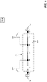
- FIG 3 it is shown an operating condition in which the switching unit 25 takes the first switching configuration SC1.
- the first charging port 21 is electrically connected to the first power transmission bus 4 and both the first and second charging ports 21, 22 are electrically disconnected from the second power transmission bus 5.
- control means 20 have commanded the first switch S1 to switch in a conduction state and the second and third switches S2, S3 to switch in an interdiction state.
- the switching unit 25 takes this switching configuration, the second charging port 22 is not fed while the first charging port 21 can provide only the DC output power transmitted by the first power transmission bus 4.
- the switching unit 25 may be conveniently commanded to take the first switching configuration SC1, when a single electric vehicle is electrically connected to the charging module 2 (namely to the first charging port 21) and a relatively low DC output power is desired or required to charge said electric vehicle.
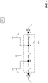
- FIG 4 it is shown an operating condition in which the switching unit 25 takes the second switching configuration SC2.
- the second charging port 22 is electrically connected to the second power transmission bus 5 and both the first and second charging ports 21, 22 are electrically disconnected from the first power transmission bus 4.
- control means 20 have commanded the second switch S2 to switch in a conduction state and the first and third switches S1, S3 to switch in an interdiction state.
- the switching unit 25 takes this switching configuration, the first charging port 21 is not fed while the second charging port 21 can provide only the DC output power transmitted by the second power transmission bus 5.
- the switching unit 25 may be conveniently commanded to take this switching configuration, when a single electric vehicle is electrically connected to the charging module 2 (namely to the second charging port 22) and a relatively low DC output power is desired or required to charge said electric vehicle.
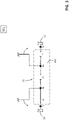
- FIG 5 it is shown an operating condition in which the switching unit 25 takes the third switching configuration SC3.
- the first charging port 21 is electrically connected to both the first and second power transmission buses 4, 5 and the second charging port 22 is electrically disconnected from both the first and second power transmission buses 4, 5.
- control means 20 have commanded the first and third switches S1, S3 to switch in a conduction state and the second switch S2 to switch in an interdiction state.
- the switching unit 25 takes this switching configuration, the second charging port 22 is not fed while the first charging port 21 can provide all the DC output power transmitted by both the first and second power transmission buses 4, 5.
- the switching unit 25 may be conveniently commanded to take this switching configuration, when a single electric vehicle is electrically connected to the charging module 2 (namely to the first charging port 21) and a relatively high DC output power is desired or required to charge said electric vehicle.
- the switching unit 25 takes the fourth switching configuration SC4.
- the second charging port 22 is electrically connected to both the first and second power transmission buses 4, 5 and the first charging port 21 is electrically disconnected from both the first and second power transmission buses 4, 5.
- the control means 20 have commanded the second and third switches S2, S3 to switch in a conduction state and the first switch S1 to switch in an interdiction state.
- the switching unit 25 takes the fourth configuration SC4, the first charging port 21 is not fed while the second charging port 22 can provide all the DC output power transmitted by both the first and second power transmission buses 4, 5.
- the switching unit 25 may be conveniently commanded to take this switching configuration, when a single electric vehicle is electrically connected to the charging module 2 (namely to the first charging port 21) and a relatively high DC output power is desired or required to charge said electric vehicle.
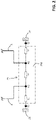
- FIG 7 it is shown an operating condition in which the switching unit 25 takes the fifth switching configuration SC5.
- the first charging port 21 is electrically connected to the first power transmission bus 4 and it is electrically disconnected to the second power transmission bus 5 while the second charging port 22 is electrically connected to the second power transmission bus 5 and it is electrically disconnected from the first power transmission bus 4.
- control means 20 have commanded the first and second switches S1, S2 to switch in a conduction state and the third switch S3 to switch in an interdiction state.
- the first charging port 21 can provide the DC output power that can be transmitted along the first power transmission bus 4 while the second charging port 21 can provide the DC output power that can be transmitted along the second power transmission bus 5.
- the switching unit 25 may be conveniently commanded to take the second switching configuration SC2, when two electric vehicles are electrically connected to the charging module 2, namely to the first and second charging ports 21, 22.
- FIG 8 it is shown an operating condition in which the switching unit 25 takes the sixth switching configuration SC6.
- both the first and second charging ports 21, 22 are electrically disconnected from both the first and second power transmission buses 4, 5.
- the control means 20 have commanded the first, second and third switches S1, S2, S3 to switch in an interdiction state.
- the switching unit 25 may be conveniently commanded to take this switching configuration, when no electric vehicles are electrically connected to the charging module 2.
- the switching unit 25 takes anyone of the above-illustrate switching configurations, the first and second power transmission buses 4, 5 are always galvanically insulated. This circumstance is particularly important when the switching unit 25 takes the fifth switching configuration SC5. In this case, in fact, the galvanic insulation between two electric vehicles electrically connected to the charging module 2 is ensured, even if the electric vehicles are charged in parallel.
- the charging station 1 including a single feeding assembly and a single charging module is briefly described with particular reference to the switching functionalities provided by the switching unit 25.
- the feeding assembly 3 of the charging station 1 is supposed to be capable of providing a maximum DC power of 300 kW to the charging module 2 while each power transmission bus is supposed to be capable of delivering a DC power of 150 kW at most.
- the switching unit 25 is in the sixth switching configuration SC6, so that both the first and second charging ports 21, 22 are not fed and are galvanically insulated from the power transmission buses 4, 5.
- control means 20 of the charging module 2 will command the switching unit 25 to switch from the sixth switching configuration SC6 to the first switching configuration SC1.
- the first charging port 21 is fed by the first power transmission bus 4 while the second charging port 22 is not fed.
- the first electric vehicle can be charged with a maximum DC power of 150 kW.
- control means 20 of the charging module 2 will command the switching unit 25 to switch from the sixth switching configuration SC6 to the third switching configuration SC3.
- the first charging port 21 is fed by both the first and second power transmission buses 4, 5 while the second charging port 22 is not fed.
- the first electric vehicle can be charged with a maximum DC power of 300 kW. All the DC power deliverable by the feeding assembly 3 can thus be employed for charging the first electric vehicle.
- the control means 20 of the charging module 2 will command the switching unit 25 to switch from the first switching configuration SC1 or the third switching configuration SC3 to the fifth switching configuration SC5.
- the first charging port 21 is fed by the first power transmission bus 4 and the second charging port 22 is fed by the second power transmission bus 5.
- a galvanic separation is still maintained between the power transmission buses 4, 5 and, therefore, between the electric vehicles coupled to the charging module 2.
- Each electric vehicle can now be charged with a maximum DC power of 150 kW. This means that the DC power deliverable by the feeding assembly 3 (300 kW) is split between the power transmission buses 4, 5 for charging both the first and second electric vehicles.
- control means 20 of the charging module 2 will command the switching unit 25 to switch from the fifth switching configuration SC5 to the second switching configuration SC2.
- the second electric vehicle can be charged with a maximum DC power of 150 kW.
- control means 20 of the charging module 2 will command the switching unit 25 to switch from the fifth switching configuration SC5 to the fourth switching configuration SC4.
- the first charging port 21 is not fed while the second charging port 22 is fed by both the first and second Power transmission buses 4, 5.
- the second electric vehicle can be charged with a maximum DC power of 300 kW. All the DC power deliverable by the feeding assembly 3 can be employed for charging the second electric vehicle.
- control means 20 of the charging module 2 will command the switching unit 25 to switch from the fifth switching configuration SC5 to the sixth switching configuration SC6.
- Both the first and second charging ports 21, 22 are not fed and are galvanically insulated from the Power transmission buses 4, 5.
- the charging station 1 can be implemented on the field according to a number of different ways depending on the installation requirements.
- FIGS. 1 , 9-14 some embodiments of a charging station 1 including a single feeding assembly 3, a single charging module 3 and a single pair of power transmission buses 4, 5 are shown.
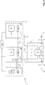
- FIG. 1 shows an embodiment of the invention, in which the feeding assembly 3 comprises a first main feeding module 31 and a second main feeding module 32 electrically connected to the charging module 2.
- the first and second main feeding module 31, 32 include the first and second feeding ports 36, 37, respectively. These latter are electrically connected to the switching unit 25 of the charging module 2 through the first and second power transmission buses 4, 5, respectively.
- the first feeding port 36 is electrically connected to the power conversion means 38 of the first main feeding module 31 while the second feeding port 27 is electrically connected to the power conversion means 38 of the second main feeding module 32.
- the first feeding port 36 and the power conversion means 38 of the first main feeding modules 31 are electrically insulated from the second feeding port 37 and the power conversion means 38 of the second main feeding modules 32.
- the first feeding module 31 is enclosed in a first self-standing power cabinet
- the second feeding module 32 is enclosed in a second self-standing power cabinet, which is distinct from the power cabinet of the first feeding module 31, while the charging module 2 is enclosed in a self-standing charging post.
- the first and second feeding modules 31, 32 may be enclosed in a same power cabinet.
- the first and second feeding modules 31, 32 and the charging module 2 may be enclosed in a same cabinet structure.
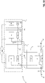
- FIGS 9-13 show embodiments of the invention, in which the feeding assembly 3 comprises one or more additional feeding modules 39 electrically connected to the first feeding module 31 or the second feeding module 32 or to both the first and second feeding modules.
- an additional feeding module 39 is electrically connected to the first main feeding module 31 only.
- the power conversion means 38 of the first main feeding module 31 and of the additional feeding module 39 are electrically connected in parallel to the first feeding port 36 of the first main feeding module 31 through a suitable switch matrix 310 of the first main feeding module 31, which is controlled by the control means 30 of this latter.
- an additional feeding module 39 is electrically connected to the first main feeding module 32 only.
- the power conversion means 38 of the second main feeding module 32 and of the additional feeding module 39 are electrically connected in parallel to the second Feeding port 37 of the second main feeding module 32 through a switch matrix 320 of the second main feeding module 32, which is controlled by the control means 30 of this latter.
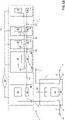
- a number N (N >1) of additional feeding modules 39 is electrically connected to the first main feeding module 31 only.
- the power conversion means 38 of the additional feeding modules 39 are electrically connected in series according to a daisy-chain configuration through suitable switch matrixes 390 included in N-1 additional feeding modules 39. Each switch matrix 390 is controlled by the control means 30 of the corresponding feeding module 39.
- the power conversion means 38 of the first main feeding module 31 and the power conversion means 38 of the series of N additional feeding modules 39 are electrically connected in parallel to the first feeding port 36 of the first main feeding module 31 through a switch matrix 310 of the first main feeding module 31, which is controlled by the control means 30 of this latter.
- a number M (M >1) of additional feeding modules 39 is electrically connected to the second main feeding module 32 only.
- the power conversion means 38 of the additional feeding modules 39 are electrically connected in series according to a daisy-chain configuration through suitable switch matrixes 390 included in M-1 additional feeding modules 39. Each switch matrix 390 is controlled by the control means 30 of the corresponding feeding module 39.
- the power conversion means 38 of the second main feeding module 32 and the power conversion means 38 of the series of M additional feeding modules 39 are electrically connected in parallel to the second feeding port 37 of the second main feeding module 32 through a switch matrix 320 of the second main feeding module 32, which is controlled by the control means 30 of this latter.
- a number N (N >1) of additional feeding modules 39 is electrically connected to the first main feeding module 31 while a number M (M >1) of additional feeding modules 39 is electrically connected to the second main feeding module 32.
- the power conversion means 38 of each series of additional feeding modules 39 are electrically connected in series according to a daisy-chain configuration through suitable switch matrixes 390 included in M-1 additional feeding modules 39. Each switch matrix 390 is controlled by the control means 30 of the corresponding feeding module 39.
- the power conversion means 38 of the first main feeding module 31 and the power conversion means 38 of the series of N additional feeding modules 39 are electrically connected in parallel to the first feeding port 36 of the first main feeding module 31 through a switch matrix 310 of the first main feeding module 31, which is controlled by the control means 30 of this latter.
- the power conversion means 38 of the second main feeding module 32 and the power conversion means 38 of the series of M additional feeding modules 39 are electrically connected in parallel to the second feeding port 37 of the second main feeding module 32 through a switch matrix 320 of the second main feeding module 32, which is controlled by the control means 30 of this latter.
- each additional feeding module 39 is enclosed in a corresponding self-standing power cabinet.
- two or additional feeding modules 39 may be enclosed in a same cabinet structure, optionally together with each of the main feeding modules 31, 32 and, possibly, with the charging module 2.
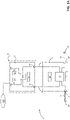
- FIG 14 shows an embodiment of the invention, in which the feeding assembly 3 comprises a single feeding module 31 electrically connected to the charging module 2.
- the feeding module 31 comprises both the first and second feeding ports 36, 37.
- each feeding ports 36, 37 is electrically connected to corresponding group 38A, 38B of power conversion means 38.
- the first and second feeding ports 36, 37 and the different groups 38A, 38B of power conversion means are electrically isolated one from another.
- the different groups 38A, 38B of power conversion means are electrically connected to the respective Feeding ports 36, 37 through a suitable switch matrix 310 of the main feeding module 31, which is controlled by the control means 30 of this latter.
- the main feeding module 31 and the charging module 2 are enclosed in a same cabinet structure.
- the main feeding module 31 may be enclosed in a self-standing power cabinet while the charging module 2 may be enclosed in a self-standing charging post.
- the charging station 1 has been described above mainly referring to embodiments including a single feeding assembly 3, a single charging module 2 and a single pair of power transmission buses 4, 5. However, this does not intend to limit the scope of the invention in any way.
- the charging station 1 may, in fact, be realized according to embodiments including multiple power assemblies 3, multiple charging modules 2 and multiple pairs of power transmission buses 4, 5, in which each pair of power transmission buses electrically connects a feeding assembly 3 with a corresponding charging module 2 ( figure 15 ).
- some modules or components of different feeding assemblies or different charging modules may be integrated one to another, according to the installation needs, even if they can provide the above-mentioned functionalities for each feeding assembly 3 or each feeding module 3.
- the switching units 25, the control means 20 and the HMIs 29 of different charging modules 2 may be integrated in a single switching arrangement, a single control arrangement and a single HMI arrangement respectively.
- the charging station 1 may be subject to further variants and modifications still falling within the scope of the invention.
- each charging module 2 may comprise multiple pairs of charging ports.
- the switching unit 25 of the charging module 2 preferably includes multiple switching circuits 250, each coupled to a corresponding pair of charging ports.
- Each switching circuit 250 can be electrically connected in a selective manner, through suitable connection switches, to the power transmission buses 4,5.
- the above-mentioned multiple pairs of charging ports may be designed to charge electric vehicles of different types, therefore according to different corresponding standards.
- the charging station may be arranged according to different layouts with respect to those described above, according to the installation requirements of the charging station.
- main feeding modules 31, 32 When multiple main feeding modules 31, 32 are arranged in a feeding assembly 3, for example, a main feeding module 31 or 32 may be enclosed together with the corresponding charging module 2 in a same cabinet structure while one or more of the remaining feeding modules may be enclosed in self-standing power cabinets.
- a feeding module 30 when arranged in a feeding assembly 3, such a feeding module may be electrically connected to one or more additional feeding modules.
- Each feeding module may be enclosed in a self-standing power cabinet while the charging module 2 may be enclosed in a self-standing charging post.
- the main feeding module 31, the additional feeding modules and the charging module 2 may be enclosed in a same cabinet structure.
- the charging station 1 Since it allows two electric vehicles to be electrically charged in parallel or a single electric vehicle to be charged by fully exploiting the electric power made available by the whole feeding assembly 3, the charging station 1 provides top level performances in terms of charging efficiency of the electric vehicles.
- the charging station 1 ensures that possible electric vehicles electrically connected to the charging module 2 are always galvanically insulated one from another, thereby being fully compliant with the international standards in terms of safety.
- the charging station 1 shows high levels of flexibility during the charging process of the electric vehicles.
- the DC output power made available for charging a given electric vehicle may be easily regulated in real time according to the actual operating status of said electric vehicle.
- the charging station 1 shows high levels of flexibility in installation as it may be easily configured on the field according to the requirements of the charging facility where the charging station has to be installed.
- the charging station 1 has proven to be relatively easy and inexpensive to manufacture at industrial levels.
Priority Applications (1)
| Application Number | Priority Date | Filing Date | Title |
|---|---|---|---|
| EP21176710.8A EP4094975A1 (fr) | 2021-05-28 | 2021-05-28 | Station de charge de haute puissance pour véhicules électriques |
Applications Claiming Priority (1)
| Application Number | Priority Date | Filing Date | Title |
|---|---|---|---|
| EP21176710.8A EP4094975A1 (fr) | 2021-05-28 | 2021-05-28 | Station de charge de haute puissance pour véhicules électriques |
Publications (1)
| Publication Number | Publication Date |
|---|---|
| EP4094975A1 true EP4094975A1 (fr) | 2022-11-30 |
Family
ID=76181047
Family Applications (1)
| Application Number | Title | Priority Date | Filing Date |
|---|---|---|---|
| EP21176710.8A Pending EP4094975A1 (fr) | 2021-05-28 | 2021-05-28 | Station de charge de haute puissance pour véhicules électriques |
Country Status (1)
| Country | Link |
|---|---|
| EP (1) | EP4094975A1 (fr) |
Citations (4)
| Publication number | Priority date | Publication date | Assignee | Title |
|---|---|---|---|---|
| US20110291616A1 (en) * | 2010-04-20 | 2011-12-01 | Moderntec Co., Ltd. | Universal charging device |
| CN207772923U (zh) * | 2017-12-19 | 2018-08-28 | 深圳市安和威电力科技股份有限公司 | 一种储能式大功率电动汽车充电站 |
| EP3521099A1 (fr) * | 2018-02-06 | 2019-08-07 | Dr. Ing. h.c. F. Porsche AG | Système de charge doté d'au moins une colonne de charge pour véhicules électriques et procédé de charge d'un ou d'une pluralité de véhicules électriques |
| CN112224081A (zh) * | 2020-10-15 | 2021-01-15 | 阳光电源股份有限公司 | 一种多枪的充电桩及充电桩电路 |
-
2021
- 2021-05-28 EP EP21176710.8A patent/EP4094975A1/fr active Pending
Patent Citations (4)
| Publication number | Priority date | Publication date | Assignee | Title |
|---|---|---|---|---|
| US20110291616A1 (en) * | 2010-04-20 | 2011-12-01 | Moderntec Co., Ltd. | Universal charging device |
| CN207772923U (zh) * | 2017-12-19 | 2018-08-28 | 深圳市安和威电力科技股份有限公司 | 一种储能式大功率电动汽车充电站 |
| EP3521099A1 (fr) * | 2018-02-06 | 2019-08-07 | Dr. Ing. h.c. F. Porsche AG | Système de charge doté d'au moins une colonne de charge pour véhicules électriques et procédé de charge d'un ou d'une pluralité de véhicules électriques |
| CN112224081A (zh) * | 2020-10-15 | 2021-01-15 | 阳光电源股份有限公司 | 一种多枪的充电桩及充电桩电路 |
Similar Documents
| Publication | Publication Date | Title |
|---|---|---|
| CN101946385B (zh) | 光伏副发电机接线盒、光伏发电机接线盒、用于光伏设备的光伏逆变器以及光伏设备 | |
| US10720775B2 (en) | Converter module for converting electrical power and inverter for a photovoltaic system having at least two converter modules | |
| US8651878B2 (en) | I/O module | |
| CN112467839B (zh) | 一种电池簇管理装置及电池储能系统 | |
| US10583749B2 (en) | Battery system and method for the operation thereof | |
| CN101789530A (zh) | 电池控制器的电位固定方式 | |
| EP4094975A1 (fr) | Station de charge de haute puissance pour véhicules électriques | |
| US10396685B2 (en) | Modular multi-stage converter | |
| EP3905473A1 (fr) | Appareil de charge et de décharge de batterie et source d'alimentation rechargeable | |
| US20230191937A1 (en) | Charging Station for Electric Vehicles | |
| JP7191497B1 (ja) | 船舶の電源系統システム、および、船舶の電源系統システムの使用方法 | |
| CN213879282U (zh) | 一种高压供电设备 | |
| CN113890397B (zh) | 低压供电网络下逆变电源辅助并网装置 | |
| EP4357190A1 (fr) | Système de charge et système de partage | |
| CN220273334U (zh) | 一种开关模块 | |
| CN113394870B (zh) | 一种交流直流通用配电板及照明系统控制方法 | |
| US11936221B2 (en) | Battery system, local electrical grid and disconnector | |
| US11979047B2 (en) | Busbar contactor matrix module | |
| CN220934900U (en) | Portable power supply conversion circuit | |
| US20240051413A1 (en) | Charging system, voltage converter unit, and accumulator unit | |
| CN200987044Y (zh) | 开关柜用后出线四极电缆转接器 | |
| GB2619009A (en) | Charging apparatus and method for providing a charging power | |
| EP3516934B1 (fr) | Système d'éclairage conçu pour alimenter au moins un bloc d'alimentation pouvant alimenter des dispositifs ou des systèmes électroniques | |
| CN117728529A (zh) | 用于监测和控制电池的系统,电池管理系统 | |
| CN117882289A (zh) | 用于产生交流电压的电路装置和方法 |
Legal Events
| Date | Code | Title | Description |
|---|---|---|---|
| PUAI | Public reference made under article 153(3) epc to a published international application that has entered the european phase |
Free format text: ORIGINAL CODE: 0009012 |
|
| STAA | Information on the status of an ep patent application or granted ep patent |
Free format text: STATUS: THE APPLICATION HAS BEEN PUBLISHED |
|
| AK | Designated contracting states |
Kind code of ref document: A1 Designated state(s): AL AT BE BG CH CY CZ DE DK EE ES FI FR GB GR HR HU IE IS IT LI LT LU LV MC MK MT NL NO PL PT RO RS SE SI SK SM TR |
|
| STAA | Information on the status of an ep patent application or granted ep patent |
Free format text: STATUS: REQUEST FOR EXAMINATION WAS MADE |
|
| 17P | Request for examination filed |
Effective date: 20230530 |
|
| RBV | Designated contracting states (corrected) |
Designated state(s): AL AT BE BG CH CY CZ DE DK EE ES FI FR GB GR HR HU IE IS IT LI LT LU LV MC MK MT NL NO PL PT RO RS SE SI SK SM TR |