EP4094725A1 - Conduit implantable extensible - Google Patents
Conduit implantable extensible Download PDFInfo
- Publication number
- EP4094725A1 EP4094725A1 EP22185870.7A EP22185870A EP4094725A1 EP 4094725 A1 EP4094725 A1 EP 4094725A1 EP 22185870 A EP22185870 A EP 22185870A EP 4094725 A1 EP4094725 A1 EP 4094725A1
- Authority
- EP
- European Patent Office
- Prior art keywords
- conduit
- mpa
- valved
- valved conduit
- layer
- Prior art date
- Legal status (The legal status is an assumption and is not a legal conclusion. Google has not performed a legal analysis and makes no representation as to the accuracy of the status listed.)
- Pending
Links
Images


Classifications
-
- A—HUMAN NECESSITIES
- A61—MEDICAL OR VETERINARY SCIENCE; HYGIENE
- A61F—FILTERS IMPLANTABLE INTO BLOOD VESSELS; PROSTHESES; DEVICES PROVIDING PATENCY TO, OR PREVENTING COLLAPSING OF, TUBULAR STRUCTURES OF THE BODY, e.g. STENTS; ORTHOPAEDIC, NURSING OR CONTRACEPTIVE DEVICES; FOMENTATION; TREATMENT OR PROTECTION OF EYES OR EARS; BANDAGES, DRESSINGS OR ABSORBENT PADS; FIRST-AID KITS
- A61F2/00—Filters implantable into blood vessels; Prostheses, i.e. artificial substitutes or replacements for parts of the body; Appliances for connecting them with the body; Devices providing patency to, or preventing collapsing of, tubular structures of the body, e.g. stents
- A61F2/02—Prostheses implantable into the body
- A61F2/24—Heart valves ; Vascular valves, e.g. venous valves; Heart implants, e.g. passive devices for improving the function of the native valve or the heart muscle; Transmyocardial revascularisation [TMR] devices; Valves implantable in the body
- A61F2/2475—Venous valves
-
- A—HUMAN NECESSITIES
- A61—MEDICAL OR VETERINARY SCIENCE; HYGIENE
- A61F—FILTERS IMPLANTABLE INTO BLOOD VESSELS; PROSTHESES; DEVICES PROVIDING PATENCY TO, OR PREVENTING COLLAPSING OF, TUBULAR STRUCTURES OF THE BODY, e.g. STENTS; ORTHOPAEDIC, NURSING OR CONTRACEPTIVE DEVICES; FOMENTATION; TREATMENT OR PROTECTION OF EYES OR EARS; BANDAGES, DRESSINGS OR ABSORBENT PADS; FIRST-AID KITS
- A61F2/00—Filters implantable into blood vessels; Prostheses, i.e. artificial substitutes or replacements for parts of the body; Appliances for connecting them with the body; Devices providing patency to, or preventing collapsing of, tubular structures of the body, e.g. stents
- A61F2/02—Prostheses implantable into the body
- A61F2/24—Heart valves ; Vascular valves, e.g. venous valves; Heart implants, e.g. passive devices for improving the function of the native valve or the heart muscle; Transmyocardial revascularisation [TMR] devices; Valves implantable in the body
- A61F2/2412—Heart valves ; Vascular valves, e.g. venous valves; Heart implants, e.g. passive devices for improving the function of the native valve or the heart muscle; Transmyocardial revascularisation [TMR] devices; Valves implantable in the body with soft flexible valve members, e.g. tissue valves shaped like natural valves
- A61F2/2418—Scaffolds therefor, e.g. support stents
-
- G—PHYSICS
- G05—CONTROLLING; REGULATING
- G05B—CONTROL OR REGULATING SYSTEMS IN GENERAL; FUNCTIONAL ELEMENTS OF SUCH SYSTEMS; MONITORING OR TESTING ARRANGEMENTS FOR SUCH SYSTEMS OR ELEMENTS
- G05B19/00—Programme-control systems
- G05B19/02—Programme-control systems electric
- G05B19/18—Numerical control [NC], i.e. automatically operating machines, in particular machine tools, e.g. in a manufacturing environment, so as to execute positioning, movement or co-ordinated operations by means of programme data in numerical form
- G05B19/4097—Numerical control [NC], i.e. automatically operating machines, in particular machine tools, e.g. in a manufacturing environment, so as to execute positioning, movement or co-ordinated operations by means of programme data in numerical form characterised by using design data to control NC machines, e.g. CAD/CAM
- G05B19/4099—Surface or curve machining, making 3D objects, e.g. desktop manufacturing
-
- A—HUMAN NECESSITIES
- A61—MEDICAL OR VETERINARY SCIENCE; HYGIENE
- A61F—FILTERS IMPLANTABLE INTO BLOOD VESSELS; PROSTHESES; DEVICES PROVIDING PATENCY TO, OR PREVENTING COLLAPSING OF, TUBULAR STRUCTURES OF THE BODY, e.g. STENTS; ORTHOPAEDIC, NURSING OR CONTRACEPTIVE DEVICES; FOMENTATION; TREATMENT OR PROTECTION OF EYES OR EARS; BANDAGES, DRESSINGS OR ABSORBENT PADS; FIRST-AID KITS
- A61F2/00—Filters implantable into blood vessels; Prostheses, i.e. artificial substitutes or replacements for parts of the body; Appliances for connecting them with the body; Devices providing patency to, or preventing collapsing of, tubular structures of the body, e.g. stents
- A61F2/02—Prostheses implantable into the body
- A61F2/24—Heart valves ; Vascular valves, e.g. venous valves; Heart implants, e.g. passive devices for improving the function of the native valve or the heart muscle; Transmyocardial revascularisation [TMR] devices; Valves implantable in the body
- A61F2/2412—Heart valves ; Vascular valves, e.g. venous valves; Heart implants, e.g. passive devices for improving the function of the native valve or the heart muscle; Transmyocardial revascularisation [TMR] devices; Valves implantable in the body with soft flexible valve members, e.g. tissue valves shaped like natural valves
- A61F2/2415—Manufacturing methods
-
- A—HUMAN NECESSITIES
- A61—MEDICAL OR VETERINARY SCIENCE; HYGIENE
- A61F—FILTERS IMPLANTABLE INTO BLOOD VESSELS; PROSTHESES; DEVICES PROVIDING PATENCY TO, OR PREVENTING COLLAPSING OF, TUBULAR STRUCTURES OF THE BODY, e.g. STENTS; ORTHOPAEDIC, NURSING OR CONTRACEPTIVE DEVICES; FOMENTATION; TREATMENT OR PROTECTION OF EYES OR EARS; BANDAGES, DRESSINGS OR ABSORBENT PADS; FIRST-AID KITS
- A61F2/00—Filters implantable into blood vessels; Prostheses, i.e. artificial substitutes or replacements for parts of the body; Appliances for connecting them with the body; Devices providing patency to, or preventing collapsing of, tubular structures of the body, e.g. stents
- A61F2/02—Prostheses implantable into the body
- A61F2/30—Joints
- A61F2002/30001—Additional features of subject-matter classified in A61F2/28, A61F2/30 and subgroups thereof
- A61F2002/30667—Features concerning an interaction with the environment or a particular use of the prosthesis
- A61F2002/30706—Features concerning an interaction with the environment or a particular use of the prosthesis specially designed for children, e.g. having means for adjusting to their growth
-
- A—HUMAN NECESSITIES
- A61—MEDICAL OR VETERINARY SCIENCE; HYGIENE
- A61F—FILTERS IMPLANTABLE INTO BLOOD VESSELS; PROSTHESES; DEVICES PROVIDING PATENCY TO, OR PREVENTING COLLAPSING OF, TUBULAR STRUCTURES OF THE BODY, e.g. STENTS; ORTHOPAEDIC, NURSING OR CONTRACEPTIVE DEVICES; FOMENTATION; TREATMENT OR PROTECTION OF EYES OR EARS; BANDAGES, DRESSINGS OR ABSORBENT PADS; FIRST-AID KITS
- A61F2210/00—Particular material properties of prostheses classified in groups A61F2/00 - A61F2/26 or A61F2/82 or A61F9/00 or A61F11/00 or subgroups thereof
- A61F2210/0004—Particular material properties of prostheses classified in groups A61F2/00 - A61F2/26 or A61F2/82 or A61F9/00 or A61F11/00 or subgroups thereof bioabsorbable
-
- A—HUMAN NECESSITIES
- A61—MEDICAL OR VETERINARY SCIENCE; HYGIENE
- A61F—FILTERS IMPLANTABLE INTO BLOOD VESSELS; PROSTHESES; DEVICES PROVIDING PATENCY TO, OR PREVENTING COLLAPSING OF, TUBULAR STRUCTURES OF THE BODY, e.g. STENTS; ORTHOPAEDIC, NURSING OR CONTRACEPTIVE DEVICES; FOMENTATION; TREATMENT OR PROTECTION OF EYES OR EARS; BANDAGES, DRESSINGS OR ABSORBENT PADS; FIRST-AID KITS
- A61F2220/00—Fixations or connections for prostheses classified in groups A61F2/00 - A61F2/26 or A61F2/82 or A61F9/00 or A61F11/00 or subgroups thereof
- A61F2220/0025—Connections or couplings between prosthetic parts, e.g. between modular parts; Connecting elements
- A61F2220/0075—Connections or couplings between prosthetic parts, e.g. between modular parts; Connecting elements sutured, ligatured or stitched, retained or tied with a rope, string, thread, wire or cable
-
- A—HUMAN NECESSITIES
- A61—MEDICAL OR VETERINARY SCIENCE; HYGIENE
- A61F—FILTERS IMPLANTABLE INTO BLOOD VESSELS; PROSTHESES; DEVICES PROVIDING PATENCY TO, OR PREVENTING COLLAPSING OF, TUBULAR STRUCTURES OF THE BODY, e.g. STENTS; ORTHOPAEDIC, NURSING OR CONTRACEPTIVE DEVICES; FOMENTATION; TREATMENT OR PROTECTION OF EYES OR EARS; BANDAGES, DRESSINGS OR ABSORBENT PADS; FIRST-AID KITS
- A61F2250/00—Special features of prostheses classified in groups A61F2/00 - A61F2/26 or A61F2/82 or A61F9/00 or A61F11/00 or subgroups thereof
- A61F2250/0004—Special features of prostheses classified in groups A61F2/00 - A61F2/26 or A61F2/82 or A61F9/00 or A61F11/00 or subgroups thereof adjustable
- A61F2250/0007—Special features of prostheses classified in groups A61F2/00 - A61F2/26 or A61F2/82 or A61F9/00 or A61F11/00 or subgroups thereof adjustable for adjusting length
-
- A—HUMAN NECESSITIES
- A61—MEDICAL OR VETERINARY SCIENCE; HYGIENE
- A61F—FILTERS IMPLANTABLE INTO BLOOD VESSELS; PROSTHESES; DEVICES PROVIDING PATENCY TO, OR PREVENTING COLLAPSING OF, TUBULAR STRUCTURES OF THE BODY, e.g. STENTS; ORTHOPAEDIC, NURSING OR CONTRACEPTIVE DEVICES; FOMENTATION; TREATMENT OR PROTECTION OF EYES OR EARS; BANDAGES, DRESSINGS OR ABSORBENT PADS; FIRST-AID KITS
- A61F2250/00—Special features of prostheses classified in groups A61F2/00 - A61F2/26 or A61F2/82 or A61F9/00 or A61F11/00 or subgroups thereof
- A61F2250/0058—Additional features; Implant or prostheses properties not otherwise provided for
- A61F2250/006—Additional features; Implant or prostheses properties not otherwise provided for modular
-
- A—HUMAN NECESSITIES
- A61—MEDICAL OR VETERINARY SCIENCE; HYGIENE
- A61F—FILTERS IMPLANTABLE INTO BLOOD VESSELS; PROSTHESES; DEVICES PROVIDING PATENCY TO, OR PREVENTING COLLAPSING OF, TUBULAR STRUCTURES OF THE BODY, e.g. STENTS; ORTHOPAEDIC, NURSING OR CONTRACEPTIVE DEVICES; FOMENTATION; TREATMENT OR PROTECTION OF EYES OR EARS; BANDAGES, DRESSINGS OR ABSORBENT PADS; FIRST-AID KITS
- A61F2250/00—Special features of prostheses classified in groups A61F2/00 - A61F2/26 or A61F2/82 or A61F9/00 or A61F11/00 or subgroups thereof
- A61F2250/0058—Additional features; Implant or prostheses properties not otherwise provided for
- A61F2250/0082—Additional features; Implant or prostheses properties not otherwise provided for specially designed for children, e.g. having means for adjusting to their growth
-
- G—PHYSICS
- G05—CONTROLLING; REGULATING
- G05B—CONTROL OR REGULATING SYSTEMS IN GENERAL; FUNCTIONAL ELEMENTS OF SUCH SYSTEMS; MONITORING OR TESTING ARRANGEMENTS FOR SUCH SYSTEMS OR ELEMENTS
- G05B2219/00—Program-control systems
- G05B2219/30—Nc systems
- G05B2219/42—Servomotor, servo controller kind till VSS
- G05B2219/42155—Model
Definitions
- Conduit selection for right ventricle outflow tract (“RVOT”) reconstruction presents a challenge in the treatment of many congenital heart diseases including tetralogy of Fallot with pulmonary atresia, truncus arteriosus, transposition of great arteries with pulmonary stenosis, congenital aortic stenosis/insufficiency, and variants of such conditions.
- RVOT right ventricle outflow tract
- homografts in many instance, may be used to replace Dacron conduit-mounted stented glutaraldehyde-treated porcine aortic valve heterografts.
- longitudinal studies have demonstrated that homografts may also require conduit replacement due to stenosis, shrinkage, calcification, and insufficiency, especially for younger patients.
- xenograft designs have been evaluated for RVOT reconstruction.
- Non-limiting examples of such xenografts may include glutaraldehyde-fixed porcine aortic valves and roots, and glutaraldehyde-fixed segments of bovine jugular veins including venous valves.
- porcine aortic valves may prove useful in RVOT procedures, stenosis and calcification issues may still persist when such xenografts are implanted in children.
- early fibrotic rind formation at the distal anastomosis, as well as significant conduit dilation and regurgitation may occur following the use of the bovine jugular veins.
- allografts and xenografts may prove to be insufficient replacements in RVOT procedures due to their poor hemodynamic performance and recurrent stenosis/insufficiency, especially in very young patients. As a result, multiple RVOT surgeries may be required until the pediatric patient reaches adulthood.
- Implanted artificial (that is, non-biological) valves may require fewer replacement surgeries than valves having a biological origin.
- such artificial valves may require significant anticoagulant therapy, especially for valves placed in the pulmonary blood stream.
- replacement artificial valves for use in pediatric/neonatal populations may be limited due to the need to custom design the valves based on intensive bioengineering studies. It may be appreciated, therefore, that there is a need for valved conduits with extended durability, especially for younger patients.
- An expanded polytetrafluoroethylene (hereafter, ePTFE) valved conduit for pediatric RVOT reconstruction may include a valve design based on the surgical experience of a physician, or the results from a computer-optimization routine specific for non-expansible conduits.
- ePTFE expanded polytetrafluoroethylene
- non-expansible conduits can provide good functionality and resistance to thrombosis, stenosis, and calcification.
- the non-expansible conduit may not be capable of accommodating the changes in anatomical structures during patient growth. Somatic growth in pediatric patients can result in the need for replacement of implanted heart valves due to stenosis and other complications if the conduit or a valved conduit is not able to accommodate the anatomic or physiological changes due to patient growth.
- an implantable device may include a conduit composed of a plastically deformable material having a yield strength of about 0.1 MPa to about 4 MPa and an ultimate tensile strength greater than about 4 MPa.
- a valved conduit may include a conduit and a valve structure disposed therein, in which the conduit is composed of at least one plastically deformable material having a yield strength of about 0.1 MPa to about 4 MPa and an ultimate tensile strength greater than about 4 MPa.
- a method of fabricating a valved conduit composed of a plastically deformable material for implantation into an animal may include obtaining at least one datum dependent at least in part on one or more anatomical structures or physiological functions of the animal, determining an initial radial dimension of the valved conduit, and determining an at least one expansion measurement for the conduit dependent at least in part on a change in the one or more anatomical structures or physiological functions.
- the plastically deformable material may have a yield strength of about 0.1 MPa to about 4 MPa and an ultimate tensile strength greater than about 4 MPa.
- the embodiments further may include calculating, using a computing device, an initial flow metric representative of a fluid flowing through an initial valved conduit having physical characteristics of an initial mathematical model of the valved conduit based at least in part on the at least one datum, the initial radial dimension, and an at least one plasticity property of the plastically deformable material. Additionally, the embodiments may include calculating, using the computing device, an at least second flow metric representative of the fluid flowing through a second valved conduit having physical characteristics of an at least second mathematical model of the valved conduit, based at least in part on the at least one datum, the expansion measurement, and the at least one plasticity property.
- the embodiments may include calculating, using the computing device, a deformation metric based at least in part on the initial flow metric and the at least one second flow metric and fabricating the valved conduit based, at least in part, on the physical characteristics of the initial mathematical model of the valved conduit if the deformation metric is greater than or equal to an acceptance value.
- a method of replacing a first valved conduit composed of a plastically deformable material implanted in an animal may include contacting an inner surface of the first valved conduit with an expansion device, causing the expansion device to expand, thereby radially increasing at least a portion of the first valved conduit, introducing a second valved conduit within at least a portion of the first valved conduit, and causing the second valved conduit to expand within the at least portion of the first valved conduit, in which the plastically deformable material has a yield strength of about 0.1 MPa to about 4 MPa and an ultimate tensile strength greater than about 4 MPa.
- plastically defonnable material means a material that may change its shape, size, or both shape and size in response to a deforming force placed thereon, and which does not fully recover its original shape, size, or both shape and size once the deforming force has been removed.
- the term “elastic material” means a material that may change its shape, size, or both shape and size in response to a deforming force placed thereon, and which recovers its original shape, size, or both shape and size once the deforming force has been removed.
- the term "deforming force” means a force that, when applied to a material, will result in a change in the shape, size, or both shape and size of the material.
- yield strength means the smallest deforming force that, when applied to a material, will result in a non-recoverable change in the shape, size, or both shape and size of the material.
- the term "ultimate tensile strength” means the smallest deforming force that, when applied to a material, will result in a break or failure of the material.
- anatomic compliance or “anatomically compliant” means the capability of a material or structure to change size, shape, or size and shape in response to the changes in anatomical structures (resulting from patient growth) within a patient in which the material or structure has been implanted.
- physiological compliance means the capability of a material or structure to maintain its structural integrity under normal physiological conditions.
- a physiologically compliant material or device may exhibit sufficient elasticity to allow the material or device to expand and return to its original shape under normal physiological conditions.
- a physiologically compliant device designed to be incorporated into the circulatory system may exhibit elasticity similar to healthy blood vessels under normal physiological conditions.
- Various embodiments of the invention are directed to implantable conduits that are physiologically compliant under physiological conditions but that can also plastically deform under non-physiological conditions allowing the conduit to be expanded radially and/or longitudinally.
- Such deformation allows for the conduit to be expanded to suit the patient's needs.
- implantable conduits may have a first physiologically appropriate radius consistent with the patient's age, size, or physical condition.
- the radius of the implantable conduit may be increased by applying sufficient radial force using, for example, a balloon catheter, to cause the implantable conduit to deform taking on a second physiologically appropriate radius.
- the radius of the implantable conduit may increase to a larger physiologically appropriate radius as a result of anatomical and/or physiological forces associated with patient growth as the patient grows. After stable expansion, the conduit will continue to be physiologically compliant under physiological conditions.
- the expandable conduit may be deformed to expand or grow with the patient, thereby reducing the need to invasive surgeries to replace the conduit as patient needs change.
- the expandable conduit disclosed herein may also be useful for replacing previously implanted homograft or other conduits that have become dysfunctional or insufficient. Additional uses for the disclosed conduit may include applications related to the treatment of pediatric and adult disorders, including other areas of the heart or more generally to other parts of the body. Some examples of additional uses may further include procedures associated with repair of pediatric left ventricular outflow tract (LVOT) pathologies as well as for use in Fontan/Kreutzer procedures. It may be further understood that such expandable conduits may find use in non-human animals for veterinary purposes as well.
- LVOT left ventricular outflow tract
- the expandable conduits of various embodiments may be composed, at least in part, of one or more biocompatible polymers that are plastically deformable under some conditions and are elastic under other conditions.
- the conduit may be elastic.
- Typical blood flow exerts up to about 0.02 MPa of pressure on the blood vessels under stress conditions or high intensity activity.
- the natural elasticity of the blood vessels allow them to radially expand to allow for increased blood flow.
- the blood vessels return to their normal diameter under lower steady state pressures.
- the expandable conduits of various embodiments exhibit similar elasticity.
- the conduits may be elastic at pressures of from about 0.0001 MPa to about 0.02 MPa, about 0.0001 MPa to about 0.015 MPa, about 0.0001 MPa to about 0.004 MPa, or any individual pressure or range encompassed by these example ranges.
- conduits of such embodiments may be deformable at non-physiological pressures greater than those described above. Therefore, as patient needs change, such conduits may be enlarged by applying pressures in excess of what would be produced by, for example, natural blood flow.
- an expandable conduit that is elastic at the pressures described above may be radially deformed by use of a balloon catheter or other device.
- such conduits may be plastically deformable at pressures (or yield strength) of, for example, about 0.05 MPa to about 2.5 MPa, about 0.3 MPa to about 2.5 MPa, about 0.1 MPa to about 4 MPa, or any range or individual pressure encompassed by these example ranges.
- the conduits may exhibit a yield strength that allows for expansion under certain physiological conditions.
- the expandable conduit may exhibit a yield strength of about 0.004 MPa to about 0.02 MPa, about 0.015 MPa to about 0.04 MPa, or any range or individual yield strength encompassed by these example ranges. Because such pressures are rarely achieved under physiological conditions, such conduits may slowly expand after implantation, and this slow expansion may allow for the conduit to expand with the growth of the patient reducing the need for manual expansion using a balloon catheter or other device.
- the conduits may typically exhibit an ultimate tensile strength that is greater than about 2.5 MPa, 3.0 MPa, 4.0 MPa, or 5.0 MPa. Such ultimate tensile strengths ensure that the conduit does not burst either under physiological conditions or at deformation pressures. In some alternative embodiments, a conduit may exhibit an ultimate tensile strength that is about 1 MPa greater than its yield strength.
- Non-limiting examples of such conduits may include a conduit having a yield strength of about 0.02 MPa and an ultimate tensile strength greater than about 1.0 MPa, a conduit having a yield strength of about 0.3 MPa and an ultimate tensile strength greater than about 1.3 MPa, a conduit having a yield strength of about 1.0 MPa and an ultimate tensile strength greater than about 2.0 MPa, a conduit having a yield strength of about 2.5 MPa and an ultimate tensile strength greater than about 3.5 MPa, and a conduit having a yield strength of about 4 MPa and an ultimate tensile strength greater than about 5 MPa.
- Conduits fabricated from materials characterized by such combinations of yield strengths and ultimate tensile strengths may be implanted into vascular structures using sutures. It may be understood that additional strength characteristics of the conduits may be related to the suture retention strength.
- the suture retention strength may be greater than or about equal to 50 gram force (about 0.5 N). In some alternative non-limiting examples, the suture retention strength may be greater than or about equal to 80 gram force (about 0.8 N).
- Embodiments of conduits having yield strengths and ultimate tensile strengths as disclosed above may be either compressed or expanded. Such compression or expansion may be provided along either the radial dimension or along the longitudinal dimension.
- a conduit may exhibit a radial expandability of about 20% to about 200% above its initial pre-expansion radius. Examples of such percent radial expandability may include, without limitation, about 20%, about 40%, about 50%, about 100%, about 150%, and about 200% above the initial pre-expansion radius, and ranges between any two of these values (including endpoints).
- a conduit may exhibit a radial compressibility of about 33% to about 83% of the initial pre-compression radius.
- percent radial compressibility may include, without limitation, about 33%, about 40%, about 45%, about 50%, about 60%, about 70%, about 80%, and about 83% of the initial pre-compression radius, and ranges between any two of these values (including endpoints).
- a conduit may exhibit a longitudinal expandability of about 5% to about 500% above the initial pre-expansion length.
- percent longitudinal expandability may include, without limitation, about 5%, about 10%, about 50%, about 100%, about 150%, about 200%, about 300%, about 400%, and about 500% above the initial pre-expansion length, and ranges between any two of these values (including endpoints).
- a conduit may exhibit a longitudinal compressibility of about 33% to about 91% of the initial pre-compression length.
- percent longitudinal compressibility may include, without limitation, about 33%, about 40%, about 50%, about 60%, about 70%, about 80%, about 90%, and about 91% of the initial pre-compression length, and ranges between any two of these values (including endpoints).
- Embodiments of the above-disclosed conduit, possessing such elastic and plastic properties may not be limited to any particular material, combination of materials, shape, size, or manner of manufacture.
- Non-limiting examples of such conduits may include other useful characteristics as disclosed below.
- the properties described above can be achieved using any means available in the art.
- materials with yield strengths of, for example, about 0.05 MPa to about 2.5 MPa, about 0.1 MPa to about 2.0 MPa, about 0.1 MPa to about 1.5 MPa, or any range or individual pressure encompassed by these example ranges can be manufactured into conduits.
- the expandable conduit may be composed of one or more biocompatible materials, and in certain embodiments, the biocompatible material may be a fluoropolymer.
- biocompatible materials may include polytetrafluoroethylene, expanded polytetrafluoroethelyne (ePTFE), polyester, polyethylene terephthalate, polydimethylsiloxane, polyurethane, and/or combinations of those materials.
- ePTFE expanded polytetrafluoroethelyne
- ePTFE expanded polytetrafluoroethelyne
- IND intermode distance
- the biocompatible material used in expandable conduits may have an internode distance of about 10 ⁇ m to about 40 ⁇ m.
- the biocompatible material may have an internode distance of less than 200 ⁇ m.
- internode distance may include, without limitation, about 20 ⁇ m, about 40 ⁇ m, about 60 ⁇ m, about 80 ⁇ m, about 100 ⁇ m, about 120 ⁇ m, about 140 ⁇ m, about 160 ⁇ m, about 180 ⁇ m, about 200 ⁇ m, and ranges between any two of these values (including endpoints).
- such materials may have a density less than about 2 g/mm 3 .
- the material may have a density of about 0.2 g/mm 3 to about 2 g/mm 3 .
- the material may have a density of about 0.2 g/mm 3 to about 0.5 g/mm 3 .
- Examples of such material density may include, without limitation, about 0.2 g/mm 3 , about 0.4 g/mm 3 , about 0.6 g/mm 3 , about 0.8 g/mm 3 , about 1.0 g/mm 3 , about 1.5 g/mm 3 , about 2.0 g/mm 3 , and ranges between any two of these values (including endpoints).
- the expandable conduit may be made of a polymer that has been coated with material having useful biomedical properties.
- the conduit may incorporate bio-active coatings.
- bio-active coatings may include one or more anti-coagulant materials.
- an anti-coagulant material may include a coumarin, heparin, a heparin derivative, a Factor Xa inhibitor, a direct thrombin inhibitor, hementin, sintered porous titanium microspheres, and/or combinations of those materials.
- the expandable conduit may be fabricated from a physically pre-treated material. Physical pre-treatment of the material may include longitudinal mechanical compression with heating. Further, additional material may be added during the pre-treatment process.
- the yield strength of a conduit fabricated from such pre-treated materials may depend on the final length or radius to which the conduit is expanded. For example, a conduit expanded either longitudinally or radially up to the original material length or radius (that is, length or radius of the material prior to compression/heating) may have a yield strength much less than that of the original material. As an example, the original material of a conduit may have a yield strength of about 10 MPa, but a conduit comprising such pre-treated material may have a yield strength of about 1 MPa for expansion up to about the original length or radius of material.
- the expandable conduit may be composed of multiple materials.
- the conduit may be composed of a material having a first yield strength and first ultimate tensile strength and may be impregnated with a second material having a second yield strength and/or second ultimate tensile strength.
- the conduit may be fabricated from two or more elastic or plastically deformable materials woven together.
- each layer of a multi-layer conduit may be composed of the same material.
- each layer of a multi-layer conduit may be composed of a different material.
- each layer of a multi-layer conduit may be composed of a material characterized by different mechanical properties.
- an inner layer of a multi-layer conduit may include a material having a first yield strength and first ultimate tensile strength and an outer layer that may include a second material having a second yield strength and/or second ultimate tensile strength.
- the first yield strength may be greater than, about equal to, or less than the second yield strength.
- the first ultimate tensile strength may be greater than, about equal to, or less than the second ultimate tensile strength.
- an inner layer may include an elastic or plastically deformable material and an outer layer may include an inelastic or frangible material.
- Conduits composed of multiple layers may have expansion capabilities depending on the material properties of the multiple layers.
- a conduit composed of a biodegradable outer layer and an elastic or plastically deformable inner layer may be expanded due to the force of a fluid flowing therein but only after the outer layer has degraded.
- a conduit having an inelastic or frangible outer layer and an elastic or plastically deformable inner layer may remain in an unexpanded state until sufficient force, for example supplied by an inserted expansion device, is applied internally to rupture the outer layer and thus permit the inner layer to expand.
- conduit materials, formulations, and/or mechanical properties may be constant over the longitudinal dimension of the conduit.
- the conduit materials, formulations, and/or mechanical properties of the conduit may vary along the length or any partial length of the conduit.
- Conduits having multiple branches may have mechanical properties that differ between the branches and/or a main cylindrical tube of the conduit.
- the conduit may form a generally cylindrical tube.
- the conduit may have a more complex geometry including having branches.
- the conduit may form a main cylindrical tube along a partial length of the conduit and then branch into two or more tubular portions.
- the conduit may form a main cylindrical tube along the length of the conduit with tubular portions extending from the main cylindrical tube. It may be understood that a conduit disclosed as being composed of a "cylindrical tube" may include any number of bends, kinks, or other deformations along the longitudinal axis of the cylindrical tube.
- the conduit may generally be any size or shape, including having a pre-expansion inner diameter greater than or equal to about 2 mm and less than about 20 mm.
- pre-expansion inner diameter may include, without limitation, about 2 mm, about 4 mm, about 6 mm, about 8 mm, about 10 mm, about 15 mm, about 20 mm, and ranges between any two of these values (including endpoints).
- the conduit may have a pre-expansion inner diameter greater than or equal to about 4 mm and less than about 14 mm.
- pre-expansion inner diameter may include, without limitation, about 4 mm, about 6 mm, about 8 mm, about 10 mm, about 12 mm, about 14 mm, and ranges between any two of these values (including endpoints).
- the conduit may have an inner diameter greater than or equal to about 8 mm and less than about 24 mm. In other examples, after expansion, the conduit may have an inner diameter greater than or equal to about 4 mm and less than about 34 mm.
- the expandable conduit may be fabricated from a plastically deformable material having a thickness of about 0.01 mm to about 2 mm.
- the conduit may have a wall thickness greater than or equal to about 10 ⁇ m and less than about 2000 ⁇ m. In other non-limiting example, the conduit may have a wall thickness of about 100 ⁇ m to about 1000 ⁇ m.
- conduit wall thickness may include, without limitation, about 10 ⁇ m, about 20 ⁇ m, about 50 ⁇ m, about 100 ⁇ m, about 200 ⁇ m, about 500 ⁇ m, about 1000 ⁇ m, about 2000 ⁇ m, and ranges between any two of these values (including endpoints).
- the mechanical properties of the expandable conduit may be about equal in or may differ between the longitudinal dimension and the radial dimension.
- an expandable conduit may have a first yield strength along the longitudinal dimension greater than 0.2 MPa, and a second yield strength along the radial dimension greater than 0.2 MPa.
- the first yield strength in a longitudinal dimension of a conduit may be greater than about 10 MPa and the second yield strength in a radial dimension of the conduit may be greater than about 2.75 MPa.
- the conduits described above may include additional components.
- the conduits may include a stent that is attached to or encapsulated by the material making up the conduit, or an inner layer may include a stent while an outer layer may include an elastic or plastically deformable material.
- a conduit may be composed of a biodegradable outer layer and an elastic or plastically deformable inner layer.
- a multi-layer expandable conduit may include a first inner layer comprising a woven material and a second outer layer comprising a woven material. It may be understood that the woven material composing the inner layer may be the same as the woven material composing the outer layer. Alternatively, the woven material composing the inner layer may differ from the woven material composing the outer layer.
- conduits composed of a variety of materials and having a variety of mechanical properties associated therewith, it may be appreciated that such materials and properties may equally apply to conduits comprising a valve structure (hereafter, a valved conduit).
- implantable conduits may include one or more sinus bulge geometries.
- a valved conduit may include one or more sinus bulges in a proximal (upstream to flow) portion with respect to a valve structure.
- a valved conduit may include one or more sinus bulges in a distal (downstream to flow) portion with respect to a valve structure.
- valved conduit Such sinus bulge geometries included in a valved conduit may be fabricated due to the application of heat and/or pressure to at least a portion of the conduit. It may be further understood that a valved conduit composed of multiple layers may have the valve structure associated with an inner-most layer. Such valved conduits may also find use for implantation in animals for veterinary purposes.
- FIG. 1 depicts a cross sectional view of an expandable valved conduit that may be implantable in an animal or human, according to one non-limiting example.
- the expandable valved conduit may include a conduit 110 constructed of synthetic material and a valve structure 120.
- the valve structure 120 may include one or more leaflet elements 125a , 125b contained within the conduit 110.
- Each of one or more leaflet elements 125a , 125b may have one or more free edges capable of motion and one or more edges which may be in mechanical communication with the conduit 110.
- the edges in mechanical communication with the conduit 110 may be affixed to an inner conduit surface.
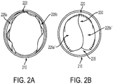
- FIGS. 2A and 2B depict a cross section view of an example of an expandable valved conduit; FIG. 2A depicts the valved conduit in an open state, and FIG. 2B depicts the valved conduit in a closed state that may result in closing of the majority of the valve's open orifice area while retaining an open gap area.
- FIGS. 2A and 2B illustrate a conduit 210 including a valve structure 220 therein.
- the valve structure 220 may be composed of two leaflets 225a and 225b . It may be understood that alternative embodiments of a valve structure 220 may include one leaflet, three leaflets, or any number of leaflets.
- FIG. 2A depicts the valved conduit in an open state in which the valve leaflets 225a and 225b may be separated by some distance and may additionally lie at least in part along the inner surface of the conduit 210 due the force of fluid flow. In the open state, the valve leaflets 225a and 225b may be disposed to provide an open orifice area therebetween that may have an orifice area almost the same as the cross-sectional area of the conduit 210.
- FIG. 2B depicts the valved conduit in a closed state.
- the valve leaflets 225a' and 225b' may be proximate to each other.
- the valve leaflets 225a' and 225b' may lie edge-to-edge with each other.
- the valve leaflets 225a' and 225b' may at least partially overlap each other.
- the valve leaflets 225a' and 225b' may be domed or partially domed.
- FIG. 2B illustrates other possible features associated with the valve structure 220.
- Such additional features may include a commissure 230 joining together at least a part of the valve leaflets 225a' and 225b', and a gap 235 between at least one free edge of at least one leaflet ( 225a' , 225b' , or both) and an inner surface of the conduit 210.
- a valve structure incorporated in a valved conduit may be constructed of the same material as those comprising the conduit, including, without limitation, a plastically deformable material, an elastic material, a non-deformable material, or mixtures thereof.
- the valve structure may be composed of the same materials and have the same mechanical properties as the conduit.
- the valve structure may be composed of the same material as the conduit but have mechanical properties differing from those of the conduit.
- the valve structure may be composed of materials that differ from those of the conduit.
- the conduit, valve structure, or both conduit and valve structure may be made of a polymer which has been coated with an anti-coagulant material.
- the conduit, valve structure, or both conduit and valve structure may incorporate bio-active coatings.
- the valved conduit may include a conduit having a first conduit layer having an inner surface in physical communication with an outer surface of a second conduit layer and a valve structure is disposed within the second conduit layer.
- the first conduit layer may be composed of a first plastically deformable material having a yield strength of about 0.1 MPa to about 4 MPa
- the second conduit layer may be composed of the same plastically deformable material as the first layer.
- the multi-layer valved conduit may be composed of a first conduit layer having a first plastically deformable material having a yield strength of about 0.1 MPa to about 4 MPa, and a second conduit layer composed of a second material that may differ from the first material.
- the valved conduit may have a first conduit layer composed of a woven material, a second conduit layer composed of a woven material, or both the first conduit layer and the second conduit layer may each be composed of a woven material.
- the first conduit layer may be biodegradable.
- the first conduit layer may include a non-plastically deformable material.
- the multi-layer valved conduit may include a stent as part of the second conduit layer.
- a computer-optimization routine is disclosed herein that may accurately and precisely simulate the geometry of different valve leaflet designs in varying positions and throughout different stages of conduit expansion. These leaflet geometries can be simulated under physiologic flow conditions through the use of computation fluid dynamics. Based on such simulations, an optimal leaflet may be designed to minimize regurgitation during ventricular diastole and maximize open orifice area during ventricular systole throughout the lifetime of the conduit.
- Valve structures incorporated into valved conduits may be designed based at least in part on modeling/optimization algorithms embodied in a computing device. Such algorithms may be used to design valve structures capable of meeting one or more acceptance criteria regarding fluid flow through the valved conduit as the conduit radially enlarges.
- the modeling/optimization algorithms may use physical data from actual patients who might require the conduit. These modeling/optimization algorithms may include Computational Fluid Dynamics (CFD), solid-mechanics modeling, and other optimization routines.
- Acceptance criteria may include measures of fluid turbulence, regurgitation, and other dynamic parameters of the fluid flow through the valve structure as the conduit radially enlarges and the valve structure changes position within the conduit.
- Additional parameters related to structural components of the valved conduit may include the area of the valve structure orifice when in the open configuration, the fluid volume flow through the open valve structure, and a measure related to the physical contact of valve structure leaflets and an inner surface of the conduit.
- modeling and/or optimization calculations may be used to reduce diastolic flow regurgitation through a heart valve structure, as well as to improve effective orifice area and overall heart valve structure function.
- a heart valve leaflet structure modeling program may predictively generate one or more heart valve leaflet structure models based, at least in part, on geometric parameters and solid-mechanics principals.
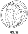
- one or more solid heart valve leaflet structure models may be analyzed according to one or more fluid flow analytical methods. For example, FIG. 3A depicts a mesh-structure model of a heart valve leaflet generated by a solid mechanical simulation algorithm; FIG. 3B depicts a solid model constructed from the mesh-structure in FIG. 3A .
- Non-limiting examples of such fluid flow analytical methods may include fluid-structure interaction (FSI) and computational fluid dynamics (CFD) simulations.
- an iterative optimization method for generating heart valve leaflet structure models may include: (1) calculating a heart valve leaflet structure model based on a set of parameters including one or more geometric parameters; (2) analyzing a performance of the heart valve leaflet structure model based at least in part on one or more fluid flow analytical methods; (3) calculating a performance cost function according to data calculated by the one or more fluid flow analytical methods; and (4) varying one or more of the heart valve leaflet structure modeling parameters in a manner to minimize the value of the valve performance cost function.
- Mathematical modeling and/or optimization calculations that may be used to calculate shapes and/or dimensions of heart valve leaflet structures may include, without limitation, computational fluid dynamics (CFD), solid-mechanics modeling, fluid/structure interaction (FSI) modeling, and blood-flow optimization algorithms.
- CFD computational fluid dynamics
- FSI fluid/structure interaction
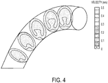
- Calculations based on CFD models may show a difference in blood flow velocity based on a curvature of the conduit component of a heart valve structure.
- FIG. 4 depicts an example of such a flow-velocity simulation.
- a blood flow model may indicate greater flow along a conduit axis having a large radius of curvature as opposed to the blood flow in a conduit having a smaller radius of curvature.
- CFD models may provide data to suggest that a curved conduit should not have a heart valve leaflet structure at the conduit bottom as a heart valve leaflet structure lower leaflet may become stuck at the closing phase, thereby leading to thrombosis.
- Mathematical calculations and/or optimization calculations may be carried out, for example, by means of one or more computing devices.
- Such computing devices may include, without limitation, one or more of the following: central processor units, numerical accelerators, static and/or dynamic memories, data storage devices, data input devices, data output devices, communication interfaces, and visual displays. While a single computing device may be used for such calculations, multiple computing devices, for example in a shared network or cloud configuration, may also be used. It may be appreciated that the one or more computing devices may operate independently or in concert.
- communications between one or more users and one or more computing devices may occur over one or more input interface device, including, without limitation, a keyboard, a mouse, a track-ball, a stylus, a voice recognition system, and/or a touch pad display.
- the one or more computing devices may provide output information to the one or more users by one or more output interface device, including, without limitation, a visual display, a printer, and/or an audio interface.
- Data communication between computing devices may occur over one or more computing system communication interface, including, but not limited to, a serial interface, a parallel interface, an Ethernet interface, a wireless interface, and/or an optical interface. Additional communications between computing devices, or between computing devices and users, may be accomplished over one or more computing system communication protocols including, but not limited to, a personal area networks (such as BlueTooth), a local area network, a wide area network, and/or a satellite network.
- a personal area networks such as BlueTooth
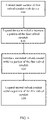
- FIG. 5 is a flow chart illustrating an embodiment of a method for designing an implantable valved conduit composed of a plastically deformable material.
- valved conduit modeling parameters may be provided 500 to the solid-mechanics modeling algorithm, the parameters including data related to the anatomy or physiology of the recipient patient.
- anatomic and/or physiologic data may include a pressure across the valve structure within the valved conduit, a fluid flow rate through the valved conduit, and physical measurements of vascular structures to which the valved conduit may be attached.
- An initial radial dimension of the valved conduit to be modeled may also be provided 505.
- data related to the expandability of the plastically deformable material may be provided to the model. Such data may include a yield strength, ultimate tensile strength, elastic modulus, and other mechanical properties of the plastically deformable material.
- a measure of expected patient anatomic growth, or changes to the patient physiology as a response of patient growth may be determined.
- the expected patient growth information, along with the data related to the plastic deformability of the valved conduit material, may be used to estimate a desired amount of expandability for the valved conduit.
- Such expandability data may be provided 510 to the modeling software as one or more expansion measurements for the conduit.
- Physical parameters associated with the initially defined valve structure may be provided to the modeling software as well. Such physical parameters may include, without limitation, a conduit length and a conduit wall thickness. Additional physical parameters may be provided to the modeling software that relate to physical dimensions of the valve structure. Some examples of such physical dimensions may be related to the shape and size of valve leaflets that may comprise the valve structure. Non-limiting examples of valve leaflet physical parameters may include one or more of a sinus edge shape, a sinus edge perimeter length, a fan edge shape, a fan edge perimeter length, a height, a fan structure height, a baseline width, and a commissure length.
- a valve structure modeling computation may then create an initial mathematical model of the initial valved conduit related to the physical and mechanical properties of the valved conduit as initially defined.
- the initial model representing the initial valved conduit may then be used in a fluid flow simulation algorithm to determine the characteristics of fluid flow through the initial valved conduit.
- One or more initial fluid flow metrics including, without limitation, a fluid velocity profile, a fluid pressure profile, and a fluid volumetric flow profile may then be calculated 515 by the fluid flow simulation algorithm.
- One or more plastic deformability characteristics of the material may also be used in such a fluid flow simulation algorithm in addition to the anatomic and/or physiological data from a patient, the initial proposed radial dimension of the conduit, and physical metrics associated with the valve structure,.
- the initial mathematical model representing the initial valved conduit may be altered to provide at least a second mathematical model representing at least a second valved conduit.
- the at least second valved conduit model may differ from the initial valved conduit model in a variety of ways, including, but not limited to, radial dimension of the conduit, valve leaflet physical parameters, expansion measurements of the material, and one or more measures related to the plasticity properties of the material (such as a change in stress or strain characteristics of the materials).
- One or more second fluid flow metrics may then be calculated 520 by the fluid flow simulation algorithm based on the at least second model of the valved conduit.
- the fluid flow simulation algorithm may be sequentially applied to additional valved conduit models, each succeeding model representing a succeeding valved conduit that has been altered in some manner from a preceding valved conduit.
- a series of valved conduits may be modeled that may differ only in their conduit radial dimensions.
- Such a series may represent a radial change of an implanted valved conduit over time as the patient grows and the conduit expands to accommodate the patent growth.
- the change in radial dimension of the valved conduit over time may be simulated by the fluid flow simulation algorithm as a change in the fluid flow metrics associated with each succeeding conduit configuration analyzed thereby.
- a deformation metric may be calculated 525.
- the deformation metric may be calculated from the multiplicity of fluid flow metrics in any number of ways, including, without limitation, an arithmetic mean of fluid flow metrics, a geometric mean of fluid flow metrics, a harmonic mean of fluid flow metrics, or a weighted average of fluid flow metrics.
- a weighted average of fluid flow metrics may be calculated as a sum of fluid flow metrics, each weighted by some weighting factor.
- a weighting factor may be derived from a flow efficiency metric or cost function associated with the effectiveness of fluid flow through a valved conduit structure having a particular set of characteristics, such as radial dimension. Efficiency may be based on a fluid flow rate, an open area within the valve structure during flow, or a measure of regurgitant flow.
- a valved conduit may be fabricated 530 from the plastically deformable material using physical characteristics of the conduit and valve structure as supplied to the initial model of the valved conduit if the calculated deformation metric is greater than or equal to an acceptance value.
- Some non-limiting examples of such acceptance values may incorporate values calculated for one or more of a regurgitation fraction, an open orifice area, and a percent leaflet/wall contact measure.
- a regurgitation fraction may measure the ratio of fluid back-flow through a valve in a closed state to the fluid forward-flow through the valve in an open state.
- An open orifice area may be calculated at a percent of a cross-sectional area of the conduit lumen not occluded by the valve structure when the valve structure is in an open position.
- An additional measure of conduit patency may include a measure of the fraction of a valve structure leaflet in contact with an inner surface of the conduit (compared to total leaflet area).
- Some examples of an acceptance value may include a regurgitation fraction less than or equal to about 30%, an open orifice area greater than or equal to about 80%, or a leaflet/wall contact value of less than or equal to about 15%.
- an implanted valved conduit fabricated from a plastically deformable material may be able to expand as the patient grows, thereby providing some long term treatment, it may be possible that a single plastically deformable valved conduit may not be sufficient to assist a patient from neonatal size to full adult size. In such an instance, it may be necessary to replace an initial valved conduit with a second valved conduit capable of expanding from an intermediate patient age to full adulthood.
- a plastically deformable valved conduit may be replaced in situ without the need for excising the original and replacing it with a second valved conduit.
- FIG. 6 is a flow chart of one method that may be used to replace an implanted first expandable valved conduit with a second expandable valved conduit.
- a first expandable valved conduit may be unable to assist a patient after some period of patient growth.
- the conduit may radially enlarge to an extent that the valve structure may no longer efficiently regulate blood flow.
- the first valved conduit may not have expanded to its fully expanded state when valve structure inefficiency may become apparent.
- the first valved conduit may be replaced by a second valved conduit by introducing the second valved conduit within the first valved conduit and expanding the second in situ.
- an expansion device such as a balloon catheter, may be introduced into the vasculature so that the expansion device contacts 600 an inner surface of the first valved conduit.
- the expansion device may then be expanded 610 within the first valved conduit thereby radially increasing at least a portion of the first valved conduit.
- a second valved conduit may then be introduced 620 within at least a portion of the expanded first valved conduit.
- the second valved conduit may be introduced using the same expansion device as used to expand the first valved conduit while the first valved conduit is expanded.
- the second valved conduit may be introduced 620 by the use of an alternative device.
- the second valved conduit may also be expanded 630 to provide a valve structure capable of regulating fluid flow through the conduit.
- Example 1 A First Plastically Deformable Material Usable in an Implantable Conduit
- FIG. 7A depicts the stress/strain curve of a first plastically deformable material that may be used to fabricate a plastically deformable and implantable conduit.
- the material has an average yield strength of about 2.1 MPa and an ultimate tensile strength of about 5 MPa.
- the material further demonstrates elastic deformation below the yield strength, characterized by an average elastic modulus of about 5.9 MPa.
- the material demonstrates an average 36% elongation above the original length at the yield stress point.
- Such a material may be favorably used for a plastically deformable conduit capable of expanding to meet the needs of a growing anatomical structure due to the extended region of the stress/strain curve indicating plastic deformability as opposed to elastic deformability.
- Example 2 A Second Plastically Deformable Material Usable in an Implantable Conduit
- FIG. 7B depicts the stress/strain curve of a second plastically deformable material that may be used to fabricate a plastically deformable and implantable conduit.
- the material demonstrates an average yield strength of about 1.7 MPa and an ultimate tensile strength of about 5.5 MPa.
- the material also has a region of elastic deformation below the yield strength characterized by an average elastic modulus of about 7.4 MPa.
- the material demonstrates an average 24% elongation above the original length at the yield stress point.
- Such a material may be favorably used for a plastically deformable conduit capable of expanding to meet the needs of a growing anatomical structure due to the extended region of the stress/strain curve indicating plastic deformability as opposed to elastic deformability.
Applications Claiming Priority (3)
| Application Number | Priority Date | Filing Date | Title |
|---|---|---|---|
| US201361851487P | 2013-03-08 | 2013-03-08 | |
| EP14761111.5A EP2964153B1 (fr) | 2013-03-08 | 2014-03-07 | Conduit extensible implantable |
| PCT/US2014/021814 WO2014138599A1 (fr) | 2013-03-08 | 2014-03-07 | Conduit extensible implantable |
Related Parent Applications (2)
| Application Number | Title | Priority Date | Filing Date |
|---|---|---|---|
| EP14761111.5A Division-Into EP2964153B1 (fr) | 2013-03-08 | 2014-03-07 | Conduit extensible implantable |
| EP14761111.5A Division EP2964153B1 (fr) | 2013-03-08 | 2014-03-07 | Conduit extensible implantable |
Publications (1)
| Publication Number | Publication Date |
|---|---|
| EP4094725A1 true EP4094725A1 (fr) | 2022-11-30 |
Family
ID=51492005
Family Applications (2)
| Application Number | Title | Priority Date | Filing Date |
|---|---|---|---|
| EP14761111.5A Active EP2964153B1 (fr) | 2013-03-08 | 2014-03-07 | Conduit extensible implantable |
| EP22185870.7A Pending EP4094725A1 (fr) | 2013-03-08 | 2014-03-07 | Conduit implantable extensible |
Family Applications Before (1)
| Application Number | Title | Priority Date | Filing Date |
|---|---|---|---|
| EP14761111.5A Active EP2964153B1 (fr) | 2013-03-08 | 2014-03-07 | Conduit extensible implantable |
Country Status (10)
| Country | Link |
|---|---|
| US (3) | US10588746B2 (fr) |
| EP (2) | EP2964153B1 (fr) |
| JP (1) | JP6706069B2 (fr) |
| CN (2) | CN111772877A (fr) |
| AU (1) | AU2014225445B2 (fr) |
| BR (1) | BR112015021889B1 (fr) |
| CA (1) | CA2904715C (fr) |
| HK (2) | HK1219866A1 (fr) |
| WO (1) | WO2014138599A1 (fr) |
| ZA (1) | ZA201506884B (fr) |
Families Citing this family (20)
| Publication number | Priority date | Publication date | Assignee | Title |
|---|---|---|---|---|
| US9554897B2 (en) | 2011-04-28 | 2017-01-31 | Neovasc Tiara Inc. | Methods and apparatus for engaging a valve prosthesis with tissue |
| CN104039271B (zh) | 2011-07-29 | 2016-09-07 | 卡内基梅隆大学 | 用于心脏重建手术的人工瓣膜化导管及其生产方法 |
| US9345573B2 (en) | 2012-05-30 | 2016-05-24 | Neovasc Tiara Inc. | Methods and apparatus for loading a prosthesis onto a delivery system |
| CN111772877A (zh) | 2013-03-08 | 2020-10-16 | 卡内基梅隆大学 | 可扩展的可植入导管 |
| US20160096318A1 (en) * | 2014-10-03 | 2016-04-07 | Disney Enterprises, Inc. | Three dimensional (3d) printer system and method for printing 3d objects with user-defined material parameters |
| US10507101B2 (en) | 2014-10-13 | 2019-12-17 | W. L. Gore & Associates, Inc. | Valved conduit |
| US11000370B2 (en) | 2016-03-02 | 2021-05-11 | Peca Labs, Inc. | Expandable implantable conduit |
| US10610357B2 (en) | 2016-10-10 | 2020-04-07 | Peca Labs, Inc. | Transcatheter stent and valve assembly |
| US11523940B2 (en) | 2017-03-17 | 2022-12-13 | W. L. Gore & Associates, Inc. | Delivery aids for glaucoma shunts |
| CN111263622A (zh) | 2017-08-25 | 2020-06-09 | 内奥瓦斯克迪亚拉公司 | 顺序展开的经导管二尖瓣假体 |
| JP7202374B2 (ja) | 2017-10-31 | 2023-01-11 | ダブリュ.エル.ゴア アンド アソシエイツ,インコーポレイティド | 弁付き導管 |
| KR102138227B1 (ko) * | 2018-08-21 | 2020-07-27 | 두산중공업 주식회사 | 유동 해석을 최적화하기 위한 장치 및 이를 위한 방법 |
| KR102189311B1 (ko) * | 2018-08-21 | 2020-12-09 | 두산중공업 주식회사 | 학습된 모델을 이용한 해석 장치 및 이를 위한 방법 |
| USD977642S1 (en) | 2018-10-29 | 2023-02-07 | W. L. Gore & Associates, Inc. | Pulmonary valve conduit |
| US11737872B2 (en) | 2018-11-08 | 2023-08-29 | Neovasc Tiara Inc. | Ventricular deployment of a transcatheter mitral valve prosthesis |
| US11678983B2 (en) | 2018-12-12 | 2023-06-20 | W. L. Gore & Associates, Inc. | Implantable component with socket |
| AU2020256195B2 (en) | 2019-04-01 | 2022-10-13 | Neovasc Tiara Inc. | Controllably deployable prosthetic valve |
| CA3140925A1 (fr) | 2019-05-20 | 2020-11-26 | Neovasc Tiara Inc. | Dispositif d'introduction avec mecanisme d'hemostase |
| EP3986332A4 (fr) | 2019-06-20 | 2023-07-19 | Neovasc Tiara Inc. | Valve mitrale prothétique à profil bas |
| WO2023039541A1 (fr) * | 2021-09-09 | 2023-03-16 | Wayne State University | Valve de dérivation à l'état solide avec régulateur de débit actif, cathéters ventriculaires et autres modes de réalisation |
Citations (3)
| Publication number | Priority date | Publication date | Assignee | Title |
|---|---|---|---|---|
| EP1064034A1 (fr) * | 1999-01-22 | 2001-01-03 | Gore Enterprise Holdings, Inc. | Implant vasculaire a ecoulement de surface ameliore |
| JP4865730B2 (ja) * | 2005-01-06 | 2012-02-01 | ボストン サイエンティフィック リミテッド | 改善された組織内方成長性をもつ、最適に膨張させた、コラーゲンで封止したePTFE移植片 |
| WO2012018779A2 (fr) * | 2010-08-02 | 2012-02-09 | Children's Medical Center Corporation | Valvule extensible et son procédé d'utilisation |
Family Cites Families (80)
| Publication number | Priority date | Publication date | Assignee | Title |
|---|---|---|---|---|
| SE392582B (sv) | 1970-05-21 | 1977-04-04 | Gore & Ass | Forfarande vid framstellning av ett porost material, genom expandering och streckning av en tetrafluoretenpolymer framstelld i ett pastabildande strengsprutningsforfarande |
| US6436135B1 (en) | 1974-10-24 | 2002-08-20 | David Goldfarb | Prosthetic vascular graft |
| US4160688A (en) | 1977-02-03 | 1979-07-10 | Johns-Manville Corporation | Low profile heat sealing iron |
| US4475972A (en) * | 1981-10-01 | 1984-10-09 | Ontario Research Foundation | Implantable material |
| US4610688A (en) * | 1983-04-04 | 1986-09-09 | Pfizer Hospital Products Group, Inc. | Triaxially-braided fabric prosthesis |
| US4816339A (en) | 1987-04-28 | 1989-03-28 | Baxter International Inc. | Multi-layered poly(tetrafluoroethylene)/elastomer materials useful for in vivo implantation |
| US4955899A (en) | 1989-05-26 | 1990-09-11 | Impra, Inc. | Longitudinally compliant vascular graft |
| US5258023A (en) | 1992-02-12 | 1993-11-02 | Reger Medical Development, Inc. | Prosthetic heart valve |
| US5466261A (en) * | 1992-11-19 | 1995-11-14 | Wright Medical Technology, Inc. | Non-invasive expandable prosthesis for growing children |
| AU671901B2 (en) | 1993-01-14 | 1996-09-12 | Meadox Medicals, Inc. | Radially Expandable Tubular Prosthesis |
| US5529830A (en) | 1994-05-25 | 1996-06-25 | W. L. Gore & Associates, Inc. | Two-way stretchable fabric laminate and articles made from it |
| US5593435A (en) * | 1994-07-29 | 1997-01-14 | Baxter International Inc. | Distensible annuloplasty ring for surgical remodelling of an atrioventricular valve and nonsurgical method for post-implantation distension thereof to accommodate patient growth |
| US6863686B2 (en) | 1995-04-17 | 2005-03-08 | Donald Shannon | Radially expandable tape-reinforced vascular grafts |
| US5800512A (en) | 1996-01-22 | 1998-09-01 | Meadox Medicals, Inc. | PTFE vascular graft |
| US5843161A (en) * | 1996-06-26 | 1998-12-01 | Cordis Corporation | Endoprosthesis assembly for percutaneous deployment and method of deploying same |
| US6016848A (en) | 1996-07-16 | 2000-01-25 | W. L. Gore & Associates, Inc. | Fluoropolymer tubes and methods of making same |
| US7452371B2 (en) * | 1999-06-02 | 2008-11-18 | Cook Incorporated | Implantable vascular device |
| US6558418B2 (en) | 1999-01-26 | 2003-05-06 | Edwards Lifesciences Corporation | Flexible heart valve |
| US6503272B2 (en) | 2001-03-21 | 2003-01-07 | Cordis Corporation | Stent-based venous valves |
| WO2002087474A1 (fr) | 2001-05-01 | 2002-11-07 | Imperial Medical Devices Limited | Prothese de valvule |
| US6939372B2 (en) | 2001-07-03 | 2005-09-06 | Scimed Life Systems, Inc. | Low profile, high stretch, low dilation knit prosthetic device |
| US6716239B2 (en) | 2001-07-03 | 2004-04-06 | Scimed Life Systems, Inc. | ePTFE graft with axial elongation properties |
| EP1406561A4 (fr) | 2001-07-16 | 2008-03-12 | Edwards Lifesciences Corp | Valvule cardiaque faisant appel au genie tissulaire |
| GB0125925D0 (en) | 2001-10-29 | 2001-12-19 | Univ Glasgow | Mitral valve prosthesis |
| US20030114924A1 (en) | 2001-12-18 | 2003-06-19 | Riyad Moe | Polymer heart valve |
| US7018404B2 (en) | 2002-01-24 | 2006-03-28 | St. Jude Medical, Inc. | Conduit for aorta or pulmonary artery replacement |
| US6752828B2 (en) | 2002-04-03 | 2004-06-22 | Scimed Life Systems, Inc. | Artificial valve |
| AU2003234505A1 (en) | 2002-05-03 | 2003-11-17 | The General Hospital Corporation | Involuted endovascular valve and method of construction |
| US7789908B2 (en) | 2002-06-25 | 2010-09-07 | Boston Scientific Scimed, Inc. | Elastomerically impregnated ePTFE to enhance stretch and recovery properties for vascular grafts and coverings |
| US7029495B2 (en) * | 2002-08-28 | 2006-04-18 | Scimed Life Systems, Inc. | Medical devices and methods of making the same |
| US6971813B2 (en) | 2002-09-27 | 2005-12-06 | Labcoat, Ltd. | Contact coating of prostheses |
| WO2005011534A1 (fr) | 2003-07-31 | 2005-02-10 | Cook Incorporated | Dispositifs a valvules prothetiques et procedes de fabrication de ces dispositifs |
| US7070616B2 (en) | 2003-10-31 | 2006-07-04 | Cordis Corporation | Implantable valvular prosthesis |
| US7261732B2 (en) * | 2003-12-22 | 2007-08-28 | Henri Justino | Stent mounted valve |
| US20050228495A1 (en) | 2004-01-15 | 2005-10-13 | Macoviak John A | Suspended heart valve devices, systems, and methods for supplementing, repairing, or replacing a native heart valve |
| US8377110B2 (en) * | 2004-04-08 | 2013-02-19 | Endologix, Inc. | Endolumenal vascular prosthesis with neointima inhibiting polymeric sleeve |
| US20060122693A1 (en) | 2004-05-10 | 2006-06-08 | Youssef Biadillah | Stent valve and method of manufacturing same |
| US7794490B2 (en) * | 2004-06-22 | 2010-09-14 | Boston Scientific Scimed, Inc. | Implantable medical devices with antimicrobial and biodegradable matrices |
| US20060161248A1 (en) | 2004-12-01 | 2006-07-20 | Case Brian C | Medical device with leak path |
| US20060149366A1 (en) | 2004-12-31 | 2006-07-06 | Jamie Henderson | Sintered structures for vascular graft |
| US7867274B2 (en) | 2005-02-23 | 2011-01-11 | Boston Scientific Scimed, Inc. | Valve apparatus, system and method |
| US7462156B2 (en) | 2005-04-11 | 2008-12-09 | Zan Mitrev | Replacement aortic valve leaflets and related technology |
| US7914569B2 (en) | 2005-05-13 | 2011-03-29 | Medtronics Corevalve Llc | Heart valve prosthesis and methods of manufacture and use |
| WO2006125055A2 (fr) | 2005-05-17 | 2006-11-23 | Cook Incorporated | Valves prothetiques et procedes de fabrication et d'utilisation afferents |
| US8500798B2 (en) | 2005-05-24 | 2013-08-06 | Edwards Lifesciences Corporation | Rapid deployment prosthetic heart valve |
| US7306729B2 (en) | 2005-07-18 | 2007-12-11 | Gore Enterprise Holdings, Inc. | Porous PTFE materials and articles produced therefrom |
| US20070027528A1 (en) | 2005-07-29 | 2007-02-01 | Cook Incorporated | Elliptical implantable device |
| US20070043431A1 (en) | 2005-08-19 | 2007-02-22 | Cook Incorporated | Prosthetic valve |
| US7569071B2 (en) | 2005-09-21 | 2009-08-04 | Boston Scientific Scimed, Inc. | Venous valve, system, and method with sinus pocket |
| US8721704B2 (en) | 2006-04-21 | 2014-05-13 | W. L. Gore & Associates, Inc. | Expandable stent with wrinkle-free elastomeric cover |
| CN101541263B (zh) | 2006-05-22 | 2013-04-24 | 塔伦·约翰·埃德温 | 组织合成-生物材料混合医疗装置 |
| US20130150943A1 (en) * | 2007-01-19 | 2013-06-13 | Elixir Medical Corporation | Biodegradable endoprostheses and methods for their fabrication |
| EP1958598A1 (fr) * | 2007-02-16 | 2008-08-20 | Universität Zürich | Prothèse d'appui tubulaire et croissante |
| WO2008106338A2 (fr) | 2007-02-28 | 2008-09-04 | Medtronic, Inc. | Système de dispositif médical implantable à élément de fixation |
| US8715337B2 (en) * | 2007-11-09 | 2014-05-06 | Cook Medical Technologies Llc | Aortic valve stent graft |
| EP3915525A1 (fr) * | 2008-02-28 | 2021-12-01 | Medtronic, Inc. | Systèmes de prothèse de valve cardiaque |
| US8696743B2 (en) | 2008-04-23 | 2014-04-15 | Medtronic, Inc. | Tissue attachment devices and methods for prosthetic heart valves |
| US20090276040A1 (en) | 2008-05-01 | 2009-11-05 | Edwards Lifesciences Corporation | Device and method for replacing mitral valve |
| EP2331016B8 (fr) | 2008-07-15 | 2020-06-03 | St. Jude Medical, LLC | Ancrage axial pliable et redéployable de valvule cardiaque prothétique pour divers états de maladie |
| US8936634B2 (en) | 2009-07-15 | 2015-01-20 | W. L. Gore & Associates, Inc. | Self constraining radially expandable medical devices |
| DE112009005236A5 (de) * | 2009-09-16 | 2012-11-15 | Bentley Surgical Gmbh | Stent mit Dehnelementen |
| US20110094592A1 (en) | 2009-10-22 | 2011-04-28 | Howard Cheng | Fluid Check Valve with a Floating Pivot |
| EP2512369B8 (fr) * | 2009-12-16 | 2017-05-17 | Neograft Technologies, Inc. | Dispositifs de greffe et procédés d'utilisation |
| EP2677965B1 (fr) | 2011-02-25 | 2017-06-21 | University of Connecticut | Valvule cardiaque prosthétique |
| US8900652B1 (en) | 2011-03-14 | 2014-12-02 | Innovatech, Llc | Marked fluoropolymer surfaces and method of manufacturing same |
| EP2522308B1 (fr) | 2011-05-10 | 2015-02-25 | Biotronik AG | Prothèse de valvule mécanique à transcathéter |
| PL2723479T3 (pl) | 2011-06-23 | 2021-12-20 | Solvay Specialty Polymers Italy S.P.A. | Sposób wytwarzania membran porowatych |
| US8603162B2 (en) | 2011-07-06 | 2013-12-10 | Waseda University | Stentless artificial mitral valve |
| CN104039271B (zh) | 2011-07-29 | 2016-09-07 | 卡内基梅隆大学 | 用于心脏重建手术的人工瓣膜化导管及其生产方法 |
| US9510935B2 (en) | 2012-01-16 | 2016-12-06 | W. L. Gore & Associates, Inc. | Articles including expanded polytetrafluoroethylene membranes with serpentine fibrils and having a discontinuous fluoropolymer layer thereon |
| US9283072B2 (en) * | 2012-07-25 | 2016-03-15 | W. L. Gore & Associates, Inc. | Everting transcatheter valve and methods |
| US10376360B2 (en) | 2012-07-27 | 2019-08-13 | W. L. Gore & Associates, Inc. | Multi-frame prosthetic valve apparatus and methods |
| CN111772877A (zh) | 2013-03-08 | 2020-10-16 | 卡内基梅隆大学 | 可扩展的可植入导管 |
| EP2967863B1 (fr) | 2013-03-15 | 2018-01-31 | Edwards Lifesciences Corporation | Conduits aortiques à valvule |
| EP2986256B1 (fr) | 2013-04-19 | 2019-04-10 | Strait Access Technologies Holdings (Pty) Ltd | Valvule cardiaque prothétique |
| EP2991585B1 (fr) | 2013-05-03 | 2023-08-16 | Medtronic Inc. | Dispositifs médicaux destinés à être implantés dans une valve |
| CA2914094C (fr) | 2014-06-20 | 2021-01-05 | Edwards Lifesciences Corporation | Valvules cardiaques identifiables apres la mise en place |
| US10507101B2 (en) | 2014-10-13 | 2019-12-17 | W. L. Gore & Associates, Inc. | Valved conduit |
| US11000370B2 (en) | 2016-03-02 | 2021-05-11 | Peca Labs, Inc. | Expandable implantable conduit |
| US10610357B2 (en) | 2016-10-10 | 2020-04-07 | Peca Labs, Inc. | Transcatheter stent and valve assembly |
-
2014
- 2014-03-07 CN CN202010631403.1A patent/CN111772877A/zh active Pending
- 2014-03-07 US US14/773,048 patent/US10588746B2/en active Active
- 2014-03-07 BR BR112015021889-0A patent/BR112015021889B1/pt active IP Right Grant
- 2014-03-07 CN CN201480025611.XA patent/CN105246430B/zh active Active
- 2014-03-07 JP JP2015561719A patent/JP6706069B2/ja active Active
- 2014-03-07 WO PCT/US2014/021814 patent/WO2014138599A1/fr active Application Filing
- 2014-03-07 EP EP14761111.5A patent/EP2964153B1/fr active Active
- 2014-03-07 EP EP22185870.7A patent/EP4094725A1/fr active Pending
- 2014-03-07 AU AU2014225445A patent/AU2014225445B2/en active Active
- 2014-03-07 CA CA2904715A patent/CA2904715C/fr active Active
-
2015
- 2015-09-16 ZA ZA2015/06884A patent/ZA201506884B/en unknown
-
2016
- 2016-07-11 HK HK16108078.0A patent/HK1219866A1/zh unknown
- 2016-07-12 HK HK16108134.2A patent/HK1220103A1/zh unknown
-
2019
- 2019-01-10 US US16/244,919 patent/US20190216605A1/en not_active Abandoned
-
2023
- 2023-01-20 US US18/157,709 patent/US20230149171A1/en active Pending
Patent Citations (3)
| Publication number | Priority date | Publication date | Assignee | Title |
|---|---|---|---|---|
| EP1064034A1 (fr) * | 1999-01-22 | 2001-01-03 | Gore Enterprise Holdings, Inc. | Implant vasculaire a ecoulement de surface ameliore |
| JP4865730B2 (ja) * | 2005-01-06 | 2012-02-01 | ボストン サイエンティフィック リミテッド | 改善された組織内方成長性をもつ、最適に膨張させた、コラーゲンで封止したePTFE移植片 |
| WO2012018779A2 (fr) * | 2010-08-02 | 2012-02-09 | Children's Medical Center Corporation | Valvule extensible et son procédé d'utilisation |
Also Published As
| Publication number | Publication date |
|---|---|
| US10588746B2 (en) | 2020-03-17 |
| WO2014138599A1 (fr) | 2014-09-12 |
| BR112015021889A2 (pt) | 2017-07-18 |
| JP6706069B2 (ja) | 2020-06-03 |
| US20160015516A1 (en) | 2016-01-21 |
| AU2014225445A1 (en) | 2015-10-01 |
| ZA201506884B (en) | 2016-10-26 |
| CA2904715A1 (fr) | 2014-09-12 |
| US20190216605A1 (en) | 2019-07-18 |
| BR112015021889B1 (pt) | 2022-02-01 |
| HK1219866A1 (zh) | 2017-04-21 |
| EP2964153B1 (fr) | 2022-08-31 |
| HK1220103A1 (zh) | 2017-04-28 |
| AU2014225445B2 (en) | 2018-09-20 |
| JP2016508852A (ja) | 2016-03-24 |
| US20230149171A1 (en) | 2023-05-18 |
| CA2904715C (fr) | 2022-07-26 |
| EP2964153A4 (fr) | 2016-11-02 |
| CN111772877A (zh) | 2020-10-16 |
| CN105246430A (zh) | 2016-01-13 |
| CN105246430B (zh) | 2020-07-28 |
| EP2964153A1 (fr) | 2016-01-13 |
Similar Documents
| Publication | Publication Date | Title |
|---|---|---|
| US20230149171A1 (en) | Expandable implantable conduit | |
| US20230404751A1 (en) | Expandable implantable conduit | |
| US11672651B2 (en) | Artificial valved conduits for cardiac reconstructive procedures and methods for their production | |
| JP6295204B2 (ja) | 開口ステントを備える心臓弁プロテーゼ | |
| Oberdier et al. | The design, development, and evaluation of a prototypic, prosthetic venous valve | |
| Claiborne III | Development and evaluation of a catheter deliverable artificial aortic heart valve prosthesis and delivery system | |
| Twardowska | Early prototyping and testing of a model of an expandable heart valve apparatus for paediatric deployment | |
| Hamid | Numerical simulation transcatheter aortic valve implantation and mechanics of valve function | |
| Jallepalli | Modeling and Analysis of a Novel Design for Application as an All-Carbon Vein Valve | |
| Heim et al. | A novel heart valve stent design: mechanical interaction with the aortic root | |
| Wang et al. | Hydrodynamic evaluation of a minimally invasive heart valve in an isolated aortic root using a modified in vitro model | |
| Kemp | Development, testing and fluid interaction simulation of a bioprosthetic valve for transcatheter aortic valve implantation |
Legal Events
| Date | Code | Title | Description |
|---|---|---|---|
| PUAI | Public reference made under article 153(3) epc to a published international application that has entered the european phase |
Free format text: ORIGINAL CODE: 0009012 |
|
| STAA | Information on the status of an ep patent application or granted ep patent |
Free format text: STATUS: THE APPLICATION HAS BEEN PUBLISHED |
|
| AC | Divisional application: reference to earlier application |
Ref document number: 2964153 Country of ref document: EP Kind code of ref document: P |
|
| AK | Designated contracting states |
Kind code of ref document: A1 Designated state(s): AL AT BE BG CH CY CZ DE DK EE ES FI FR GB GR HR HU IE IS IT LI LT LU LV MC MK MT NL NO PL PT RO RS SE SI SK SM TR |
|
| STAA | Information on the status of an ep patent application or granted ep patent |
Free format text: STATUS: REQUEST FOR EXAMINATION WAS MADE |
|
| 17P | Request for examination filed |
Effective date: 20230525 |
|
| RBV | Designated contracting states (corrected) |
Designated state(s): AL AT BE BG CH CY CZ DE DK EE ES FI FR GB GR HR HU IE IS IT LI LT LU LV MC MK MT NL NO PL PT RO RS SE SI SK SM TR |