EP4094596A1 - Power supply unit and cartridge for aerosol generation device, and method for determining type of cartridge - Google Patents
Power supply unit and cartridge for aerosol generation device, and method for determining type of cartridge Download PDFInfo
- Publication number
- EP4094596A1 EP4094596A1 EP20915084.6A EP20915084A EP4094596A1 EP 4094596 A1 EP4094596 A1 EP 4094596A1 EP 20915084 A EP20915084 A EP 20915084A EP 4094596 A1 EP4094596 A1 EP 4094596A1
- Authority
- EP
- European Patent Office
- Prior art keywords
- cartridge
- power supply
- supply unit
- light
- emitting element
- Prior art date
- Legal status (The legal status is an assumption and is not a legal conclusion. Google has not performed a legal analysis and makes no representation as to the accuracy of the status listed.)
- Withdrawn
Links
- 239000000443 aerosol Substances 0.000 title claims abstract description 100
- 238000000034 method Methods 0.000 title claims description 33
- 238000001514 detection method Methods 0.000 claims description 40
- 230000004044 response Effects 0.000 claims description 21
- 230000009471 action Effects 0.000 claims description 12
- 230000003213 activating effect Effects 0.000 claims description 4
- 238000010276 construction Methods 0.000 description 30
- 239000002775 capsule Substances 0.000 description 25
- 239000000796 flavoring agent Substances 0.000 description 20
- 235000019634 flavors Nutrition 0.000 description 20
- 238000007599 discharging Methods 0.000 description 15
- 230000004048 modification Effects 0.000 description 9
- 238000012986 modification Methods 0.000 description 9
- 230000000903 blocking effect Effects 0.000 description 7
- 239000007789 gas Substances 0.000 description 5
- 239000008368 mint flavor Substances 0.000 description 5
- 238000000889 atomisation Methods 0.000 description 4
- 238000010586 diagram Methods 0.000 description 4
- 239000000463 material Substances 0.000 description 4
- 241000208125 Nicotiana Species 0.000 description 3
- 235000002637 Nicotiana tabacum Nutrition 0.000 description 3
- DNIAPMSPPWPWGF-UHFFFAOYSA-N Propylene glycol Chemical compound CC(O)CO DNIAPMSPPWPWGF-UHFFFAOYSA-N 0.000 description 3
- 238000004891 communication Methods 0.000 description 3
- 238000005485 electric heating Methods 0.000 description 3
- 238000003780 insertion Methods 0.000 description 3
- 230000037431 insertion Effects 0.000 description 3
- 239000007788 liquid Substances 0.000 description 3
- 230000008569 process Effects 0.000 description 3
- 239000011347 resin Substances 0.000 description 3
- 229920005989 resin Polymers 0.000 description 3
- PEDCQBHIVMGVHV-UHFFFAOYSA-N Glycerine Chemical compound OCC(O)CO PEDCQBHIVMGVHV-UHFFFAOYSA-N 0.000 description 2
- 239000000919 ceramic Substances 0.000 description 2
- 230000008859 change Effects 0.000 description 2
- 239000008373 coffee flavor Substances 0.000 description 2
- 238000002485 combustion reaction Methods 0.000 description 2
- 239000003814 drug Substances 0.000 description 2
- 239000003571 electronic cigarette Substances 0.000 description 2
- 238000010438 heat treatment Methods 0.000 description 2
- 230000007246 mechanism Effects 0.000 description 2
- 239000006199 nebulizer Substances 0.000 description 2
- 239000002994 raw material Substances 0.000 description 2
- NOOLISFMXDJSKH-UTLUCORTSA-N (+)-Neomenthol Chemical compound CC(C)[C@@H]1CC[C@@H](C)C[C@@H]1O NOOLISFMXDJSKH-UTLUCORTSA-N 0.000 description 1
- 229920000742 Cotton Polymers 0.000 description 1
- NOOLISFMXDJSKH-UHFFFAOYSA-N DL-menthol Natural products CC(C)C1CCC(C)CC1O NOOLISFMXDJSKH-UHFFFAOYSA-N 0.000 description 1
- 241000196324 Embryophyta Species 0.000 description 1
- 229910001218 Gallium arsenide Inorganic materials 0.000 description 1
- HBBGRARXTFLTSG-UHFFFAOYSA-N Lithium ion Chemical compound [Li+] HBBGRARXTFLTSG-UHFFFAOYSA-N 0.000 description 1
- 235000006679 Mentha X verticillata Nutrition 0.000 description 1
- 235000002899 Mentha suaveolens Nutrition 0.000 description 1
- 235000001636 Mentha x rotundifolia Nutrition 0.000 description 1
- XUIMIQQOPSSXEZ-UHFFFAOYSA-N Silicon Chemical compound [Si] XUIMIQQOPSSXEZ-UHFFFAOYSA-N 0.000 description 1
- 230000002159 abnormal effect Effects 0.000 description 1
- 230000004913 activation Effects 0.000 description 1
- 125000003118 aryl group Chemical group 0.000 description 1
- 230000005540 biological transmission Effects 0.000 description 1
- 239000003990 capacitor Substances 0.000 description 1
- 230000008094 contradictory effect Effects 0.000 description 1
- 230000002950 deficient Effects 0.000 description 1
- 230000000694 effects Effects 0.000 description 1
- 230000005674 electromagnetic induction Effects 0.000 description 1
- 239000003365 glass fiber Substances 0.000 description 1
- 235000011187 glycerol Nutrition 0.000 description 1
- 229910001416 lithium ion Inorganic materials 0.000 description 1
- 229940041616 menthol Drugs 0.000 description 1
- 238000012545 processing Methods 0.000 description 1
- 230000001007 puffing effect Effects 0.000 description 1
- 239000004065 semiconductor Substances 0.000 description 1
- 229910052710 silicon Inorganic materials 0.000 description 1
- 239000010703 silicon Substances 0.000 description 1
- 238000012546 transfer Methods 0.000 description 1
- XLYOFNOQVPJJNP-UHFFFAOYSA-N water Substances O XLYOFNOQVPJJNP-UHFFFAOYSA-N 0.000 description 1
- 238000004804 winding Methods 0.000 description 1
Images


Classifications
-
- A—HUMAN NECESSITIES
- A24—TOBACCO; CIGARS; CIGARETTES; SIMULATED SMOKING DEVICES; SMOKERS' REQUISITES
- A24F—SMOKERS' REQUISITES; MATCH BOXES; SIMULATED SMOKING DEVICES
- A24F40/00—Electrically operated smoking devices; Component parts thereof; Manufacture thereof; Maintenance or testing thereof; Charging means specially adapted therefor
- A24F40/50—Control or monitoring
- A24F40/53—Monitoring, e.g. fault detection
-
- A—HUMAN NECESSITIES
- A24—TOBACCO; CIGARS; CIGARETTES; SIMULATED SMOKING DEVICES; SMOKERS' REQUISITES
- A24F—SMOKERS' REQUISITES; MATCH BOXES; SIMULATED SMOKING DEVICES
- A24F40/00—Electrically operated smoking devices; Component parts thereof; Manufacture thereof; Maintenance or testing thereof; Charging means specially adapted therefor
- A24F40/50—Control or monitoring
- A24F40/51—Arrangement of sensors
-
- A—HUMAN NECESSITIES
- A24—TOBACCO; CIGARS; CIGARETTES; SIMULATED SMOKING DEVICES; SMOKERS' REQUISITES
- A24F—SMOKERS' REQUISITES; MATCH BOXES; SIMULATED SMOKING DEVICES
- A24F40/00—Electrically operated smoking devices; Component parts thereof; Manufacture thereof; Maintenance or testing thereof; Charging means specially adapted therefor
- A24F40/10—Devices using liquid inhalable precursors
-
- A—HUMAN NECESSITIES
- A24—TOBACCO; CIGARS; CIGARETTES; SIMULATED SMOKING DEVICES; SMOKERS' REQUISITES
- A24F—SMOKERS' REQUISITES; MATCH BOXES; SIMULATED SMOKING DEVICES
- A24F40/00—Electrically operated smoking devices; Component parts thereof; Manufacture thereof; Maintenance or testing thereof; Charging means specially adapted therefor
- A24F40/40—Constructional details, e.g. connection of cartridges and battery parts
- A24F40/42—Cartridges or containers for inhalable precursors
Abstract
Description
- The present disclosure relates to a power supply unit and a cartridge of an aerosol generation device and a method for judging types of cartridges.
- Aerosol generation devices, such as an electronic cigarette, a nebulizer, and so on which generate gases, to which flavor components which are to be inhaled by users have been added, have been widely spread. Components which contribute to generation of a flavor-component-added gas, for example, an aerosol source for generating aerosol, a flavor source for adding flavor to the aerosol, and so on, are attached to an aerosol generation device. The contents stored in the above components are consumed every time when a gas is generated. By sucking a flavor-component-added gas (in the following description, this action may also be referred to as puffing) which has been generated by the aerosol generation device, a user can taste the flavor together with the gas.
-
- PTL 1:
Japanese Patent Application Public Disclosure No. 2018-512141 - PTL 2:
Japanese Patent Application Public Disclosure No. 2017-538420 - PTL 3:
Japanese Patent Application Public Disclosure No. 2012-513750 - PTL 4:
Japanese Patent Application Public Disclosure No. 2015-535760 - It is desirable to effectively utilize components while providing a user with sufficient suction experience. Accordingly, one of objects of the present disclosure is to make it possible, by improving mechanisms of components and an aerosol generation device, to judge types of the components easily when a component is attached to the aerosol generation device, and control operation of the aerosol generation device according to the type.
- For achieving the above-explained object, according to a first aspect, a power supply unit for an aerosol generation device is provided. The power supply unit comprises a light emitting element, a light receiving element, and a controller which makes, through operation that makes the light emitting element emit light, operation for detecting a cartridge be performed when the power supply unit is connected to the cartridge, and judges the type of the cartridge based on result of the detecting.
- According to the power supply unit of the aerosol generation device, the type of a cartridge can be judged easily and precisely. Further, operation of the aerosol generation device can be controlled according to the type. Thus, it becomes possible to provide a user with sufficient suction experience.
- A power supply unit according to a second aspect comprises the power supply unit according to the first aspect, wherein light emitted toward the light receiving element from the light emitting element is blocked as a result that a protrusion constructed in the cartridge moves between the light emitting element and the light receiving element; the numbers of protrusions of the cartridges are different according to the types of the cartridges, respectively; and result of the detecting may comprise the number of times that the light is blocked.
- A power supply unit according to a third aspect comprises the power supply unit according to the first aspect, wherein signal strength of light emitted from the light emitting element and received by the light receiving element is adjusted as a result that a protrusion constructed in the cartridge moves between the light emitting element and the light receiving element; the shapes of the protrusions of the cartridges are different according to the types of the cartridges, respectively; and result of the detecting may comprise the signal strength of light adjusted through the shape of the protrusion in the cartridge.
- A power supply unit according to a fourth aspect comprises the power supply unit according to one of the first aspect to the third aspect, wherein the light emitting element and the light receiving element may be arranged, on a surface whereat the power supply unit is connected to the cartridge in an axial direction, in such a manner that they are positioned along a circumferential direction to face each other.
- A power supply unit according to a fifth aspect comprises the power supply unit according to one of the first aspect to the fourth aspect, wherein the controller may start operation for detecting the cartridge in response to reception, by the light receiving element, of light having first signal strength, and may terminate the operation for detecting the cartridge in response to reception, by the light receiving element, of light having second signal strength.
- A power supply unit according to a sixth aspect comprises the power supply unit according to the fifth aspect, wherein the controller may judge, in response to reception of light having third signal strength that is smaller than the first signal strength and the second signal strength, that the light is blocked.
- A power supply unit according to a seventh aspect comprises the power supply unit according to one of the first aspect to the sixth aspect, and comprises a first pair of a light emitting element and a light receiving element and a second pair of a light emitting element and a light receiving element; wherein the controller may judge the type of the cartridge, based on result of the detecting in the first pair of the light emitting element and the light receiving element and result of the detecting in the second pair of the light emitting element and the light receiving element.
- A power supply unit according to an eighth aspect comprises the power supply unit according to one of the first aspect to the seventh aspect, and further comprises a physical switch, wherein the physical switch may be pressed by the cartridge when the power supply unit is connected to the cartridge, and the controller may make the light emitting element start emission of light in response to an event that the physical switch is pressed.
- A power supply unit according to a ninth aspect comprises the power supply unit according to the eighth aspect, wherein the controller may make the light emitting element terminate emission of light in response to an event that the physical switch is pressed again by the cartridge.
- A power supply unit according to a tenth aspect comprises the power supply unit according to one of the first aspect to the eighth aspect, wherein the controller may make the light emitting element terminate emission of light in response to completion of judgment of the type of the cartridge based on result of the detecting.
- A power supply unit according to an eleventh aspect comprises the power supply unit according to one of the first aspect to the tenth aspect, wherein the controller may judge, when the cartridge is not detected for a predetermined period of time after starting of emission of the light by the light emitting element, that connection of the power supply unit to the cartridge is failed, and may make the light emitting element terminate emission of the light.
- A power supply unit according to a twelfth aspect comprises the power supply unit according to the eleventh aspect, and further comprises a notifier, wherein the controller may make the notifier notify the failure of connection.
- A power supply unit according to a thirteenth aspect comprises the power supply unit according to the twelfth aspect, wherein the notification of the failure of connection may be used to prompt a user to again perform action to connect the power supply unit to the cartridge.
- A power supply unit according to a fourteenth aspect comprises the power supply unit according to one of the first aspect to the thirteenth aspect, wherein the controller may prohibit supplying of electric power to the cartridge in the case that the type of the cartridge cannot be judged.
- A power supply unit according to a fifteenth aspect comprises the power supply unit according to the first aspect, wherein light from the light emitting element is reflected toward the light receiving element as a result that a protrusion constructed in the cartridge moves in a space close to the light emitting element and the light receiving element; the numbers of protrusions of the cartridges are different according to the types of the cartridges, respectively; and result of the detecting may comprise the number of times that the light emitted from the light emitting element is received by the light receiving element.
- According to a sixteenth aspect, a cartridge, which is to be connected to the power supply unit according to one of the first aspect to the fifteenth aspect and comprises a protruding member, is provided, wherein the protruding members are different according to the types, respectively.
- According to a seventeenth aspect, a cartridge for an aerosol generation device is provided. The cartridge is provided with a protruding member, wherein the protruding members are different according to the types, respectively; and, when the cartridge is connected to a power supply unit of the aerosol generation device, detection of the protruding member is performed by a photosensor included in the power supply unit, and the type is judged based on result of the detection.
- According to the cartridge for the aerosol generation device, the type of a cartridge can be judged easily and precisely. Further, operation of the aerosol generation device can be controlled according to the type. Thus, it becomes possible to provide a user with sufficient suction experience.
- A cartridge according to an eighteenth aspect comprises the cartridge according to the seventeenth aspect, wherein: the protruding member may comprise a number of protrusions, wherein the numbers of protrusions of the cartridges are different according to the types of the cartridges, respectively; when the cartridge is connected to the power supply unit, the protrusion may move between a light emitting element and a light receiving element which are included in the photosensor and may accordingly block light emitted toward the light receiving element from the light emitting element; and the type may be judged based on the number of times that the light is blocked by the protrusion.
- A cartridge according to a nineteenth aspect comprises the cartridge according to the seventeenth aspect or the eighteenth aspect, wherein the aerosol generation device comprises a cartridge case which holds the cartridge and is attached to the power supply unit in an axial direction; when viewed from the axial direction, a cross section of the cartridge has a concave shape that corresponds to a convex shape of a cross section of part of a hollow part of the cartridge case; and the cross section of the cartridge may be aligned, in a circumferential direction, with the cross section of the part of the hollow part of the cartridge case, so that said cartridge is inserted in the hollow part of the cartridge case in the axial direction.
- According to a twentieth aspect, a method for judging the type of a cartridge is provided. The method comprises steps, that are performed by a power supply unit of an aerosol generation device when the cartridge is connected in an axial direction to the power supply unit, for: activating a photosensor included in the power supply unit; counting the number of times that light emitted toward a light receiving element from the light emitting element in the photosensor is blocked by a protruding member of the cartridge, wherein the light is blocked as a result that a protrusion of the protruding member moves between the light emitting element and the light receiving element in the photosensor during the time when the cartridge is rotated relative to the power supply unit about an axis by a predetermined distance; and judging the type of the cartridge based on the counted number of times; wherein the numbers of protrusions in the protruding members of the cartridges are different according to the types of the cartridges, respectively.
- According to the method for judging the type of a cartridge, the type of a cartridge can be judged easily and precisely. Further, operation of the aerosol generation device can be controlled according to the type. Thus, it becomes possible to provide a user with sufficient suction experience.
-
-
Fig. 1 is a perspective view of an aerosol generation device. -
Fig. 2 is the other perspective view of the aerosol generation device inFig. 1 . -
Fig. 3 is a cross-section view of the aerosol generation device inFig. 1 . -
Fig. 4 is a perspective view of a power supply unit in an embodiment. -
Fig. 5 is a block diagram of a power supply unit in an embodiment. -
Fig. 6 is an exploded view of an aerosol generation device. -
Fig. 7 is a schematic perspective view of a photosensor installed in a power supply unit in an embodiment. -
Fig. 8A is a schematic perspective view of a power supply unit in an embodiment. -
Fig. 8B is a top view of the power supply unit inFig. 8A viewed from an axial direction. -
Fig. 9A is a schematic perspective view of a cartridge in an embodiment. -
Fig. 9B is a top view of the cartridge inFig. 9A viewed from an axial direction. -
Fig. 10 is a flowchart showing operation for judging the type of a cartridge according to an embodiment. -
Fig. 11A is a cross-section view of acartridge case 27 in a modification example viewed from an axial direction. -
Fig. 11B is a cross-section view of acartridge 200 in a modification example viewed from an axial direction. -
Fig. 12 is a schematic perspective view of a modification example of a power supply unit which is provided with a physical switch. -
Fig. 13 is a block diagram of a power supply unit in a different embodiment. - In the following description, embodiments of the present disclosure will be explained with reference to figures. In the attached figures, the same or similar reference symbols are assigned to the same or similar components, and overlapping explanation of the same or similar components may be omitted in the explanation of respective embodiments. Further, a characteristic shown in each embodiment can be applied to the other embodiment as long as they are not contradictory to each other. Further, the figures are drawn in a schematic manner, so that actual sizes, ratios, and so on may not always coincide with those in the figures. Also, in the figures, a figure may include a part wherein relationship in terms of the size, the ratio, or the like is different from that relating to a corresponding part in the other figure.
- It should be reminded that, although aerosol generation devices comprise an electronic cigarette and a nebulizer in the embodiments of the present disclosure, the aerosol generation devices are not limited to those listed above. That is, the aerosol generation devices may comprise various inhalers, each generating aerosol or flavor-added aerosol sucked by a user. Further, the generated inhaled component source may include invisible vapor, in addition to aerosol.
- Each of
Fig. 1 to Fig. 5 shows anaerosol generation device 1 to which apower supply unit 10 has been attached. Each ofFigs. 1 and2 is a perspective view of theaerosol generation device 1, andFig. 3 is a cross-section view of theaerosol generation device 1.Fig. 4 is a perspective view of thepower supply unit 10 included in theaerosol generation device 1, andFig. 5 is a block diagram showing a construction example of thepower supply unit 10. - The
aerosol generation device 1 is an apparatus for making a user suck flavor without requiring combustion, and has a stick shape extending in a predetermined direction (hereinafter, the direction will be referred to as a longitudinal direction A). As shown inFigs. 1 and2 , theaerosol generation device 1 comprises thepower supply unit 10, acartridge unit 20, and acapsule unit 30 arranged in the longitudinal direction A in this order. Thecartridge unit 20 is attachable/detachable to/from thepower supply unit 10, and thecapsule unit 30 is attachable/detachable to/from thecartridge unit 20. In other words, thecartridge unit 20 and thecapsule unit 30 are attachable/detachable with each other. - As shown in
Figs. 3 and4 , thepower supply unit 10 in the present embodiment includes, in the inside of a powersupply unit case 11 having a cylindrical shape, apower supply 12, acharger 13, acontroller 50, various kinds of sensors, and so on. Thepower supply 12 is a chargeable secondary battery, an electric double layer capacitor, or the like, and, preferably, is a lithium-ion battery. - A
top part 11a positioned in the side of one of ends, in the longitudinal direction A, of the power supply unit case 11 (the side close to the cartridge unit 20) is provided with dischargingterminals 41. The dischargingterminals 41 are constructed in such a manner that they protrude toward thecartridge unit 20 from the top surface of thetop part 11a, and can be electrically connected to aload 21 in thecartridge unit 20. - Further, an
air supplying part 42 for supplying air to theload 21 in thecartridge unit 20 is constructed in a part close to the dischargingterminals 41 on the top surface of thetop part 11a. As will be explained later, in thepower supply unit 10 of the present embodiment, the top surface of thetop part 11a is further provided with a photosensor 17 which comprises (a pair comprising) alight emitting element 171 and alight receiving element 172. - The
top part 11a is capped by a connection cap (not shown in the figure). The connection cap forms a connection surface whereat thepower supply unit 10 connects to thecartridge unit 20 in the longitudinal direction A. The connection cap is formed by using resin material that is softer than silicon resin and has elasticity; and the tip side of each of the dischargingterminals 41, theair supplying part 42, and the photosensor 17 protrudes toward thecartridge unit 20 from the connection cap. - A
bottom part 11b positioned in the side of the other of the ends, in the longitudinal direction, of the power supply unit case 11 (the side opposite to the cartridge unit 20) is provided with a chargingterminal 43 which can be electrically connected to an external electric power source (not shown in the figure) which can charge thepower supply 12. The chargingterminal 43 is constructed in the side surface of thebottom part 11b, and can be connected to at least one of a USB terminal, a microUSB terminal, and a Lightning terminal. - In this regard, the charging
terminal 43 may be an electric power receiver which can receive, in a noncontact manner, electric power transmitted from an external electric power source. In such a case, the charging terminal 43 (the electric power receiver) may comprise an electric power receiving coil. The type of the system for transmitting electric power in a noncontact manner (Wireless Power Transfer) may be an electromagnetic induction type or a magnetic resonance type. Further, the chargingterminal 43 may be an electric power receiver which can receive, in a contactless manner, electric power transmitted from an external terminal. In a different example, the chargingterminal 43 may be that which can be connected to at least one of a USB terminal, a microUSB terminal, and a Lightning terminal, and also has the above-explained electric power receiver. - That is, in the
power supply unit 10, the dischargingterminal 41 and the chargingterminal 43 are constructed as separate components and positioned apart from each other in the longitudinal direction A, so that it is constructed in such a manner that an external electric power source can be electrically connected to the chargingterminal 43 during the state that discharging of thepower supply 12 via the dischargingterminals 41 is possible. - Further, in the power
supply unit case 11, anoperation unit 14, which can be manipulated by a user, is constructed in a side surface of thetop part 11a in such a manner that it faces a side opposite to a side to which the chargingterminal 43 faces. In more detail, theoperation unit 14 and the chargingterminal 43 have point symmetric relationship with respect to an intersection point of a straight line connecting theoperation unit 14 and the chargingterminal 43 and a center axial line L of thepower supply unit 10 in the longitudinal direction A. Theoperation unit 14 comprises a button-type switch, a touch panel, or the like, and is used when operation for activating/shutting-down thecontroller 50 and various kinds of sensors, or other operation, is performed to reflect intention, with respect to use, of a user. Thecontroller 50 and aninhalation sensor 15 for detecting a puff action are arranged in a position close to theoperation unit 14. - The
charger 13 is positioned close to the chargingterminal 43, and controls charging electric power inputted from the chargingterminal 43 to thepower supply 12. Thecharger 13 comprises a converter for converting direct current from an inverter and so on, which are installed on a charging cable connected to the chargingterminal 43 and convert alternate current to direct current, to direct current having different magnitude, a voltmeter, an ammeter, a processor, and so on. - As shown in
Fig. 5 , thecontroller 50 is connected to theoperation unit 14, theinhalation sensor 15 for detecting a puff (inhalation) action, avoltage sensor 16 for measuring a voltage of thepower supply 12, various kinds of sensors such as thephotosensor 17 and so on, and amemory 18 for storing the number of times of puff actions or the length of time of energization to theload 21, and so on, and performs control of various kinds of operation of theaerosol generation device 1. Theinhalation sensor 15 may be constructed by using a condenser microphone, a pressure sensor, or the like. The photosensor 17 may be constructed to include thelight emitting element 171 and thelight receiving element 172. - Specifically, the
controller 50 is a processor (computer). More specifically, the structure of the processor comprises an electric circuit formed by combining circuit elements such as a semiconductor element and so on. Details of thecontroller 50 will be explained later. - Further, the power
supply unit case 11 is provided with an air taking-in opening (not shown in the figure) for taking the outside air in the inside thereof. In this regard, the air taking-in opening may be formed in a circumference area of theoperation unit 14, or may be formed in a circumference area of the chargingterminal 43. - As shown in
Fig. 3 , thecartridge unit 20 comprises, in the inside of acylindrical cartridge case 27, areservoir 23 for storing an aerosol source 22, theelectrical load 21 for atomizing the aerosol source 22, awick 24 for drawing the aerosol source from thereservoir 23 to theload 21, anaerosol flow path 25 through which aerosol, that is generated as a result of atomization of the aerosol source 22, flows toward thecapsule unit 30, and anend cap 26 which can house a part of thecapsule unit 30. - In the present case, a member comprising the
reservoir 23, theload 21, thewick 24, and theaerosol flow path 25 may be constructed as acartridge 200. Regarding thecartridge 200, one end thereof can be connected to thepower supply unit 10 and the other end thereof can be connected to theend cap 26. - The compartment for the
reservoir 23 is formed to surround the periphery of theaerosol flow path 25, and stores the aerosol source 22. A porous body comprising a resin web, cotton, or the like may be included in thereservoir 23, and the porous body may be impregnated with theaerosol source 23. The aerosol source 22 includes a liquid such as glycerin, propylene glycol, water, or the like. - The
wick 24 is a liquid holding member for drawing the aerosol source 22 from thereservoir 23 to theload 21 by capillary effect, and comprises glass fibers, porous ceramics, or the like, for example. - The load atomizes, without combustion, the aerosol source 22 by using electric power supplied from the
power supply 12 via the dischargingterminals 41. Theload 21 comprises a wound electric heating wire (a coil) having a predetermined winding pitch. In this regard, theload 21 can be any element which can generate aerosol by atomizing the aerosol source 22, for example, a heater element or an ultrasonic generator. Examples of the heater elements that can be listed are a heating resistor, a ceramic heater, an induction-heating-type heater, and so on. - The
aerosol flow path 25 is formed in the area downstream theload 21 and along the axial line L of thepower supply unit 10. - The
end cap 26 comprises acartridge housing part 26a for housing a part of thecapsule unit 30 and acommunication path 26b for communication between theaerosol flow path 25 and thecartridge housing part 26a. - An end of the
capsule unit 30, which is in the side close to thecartridge unit 20, is housed in an attachable/detachable manner in thecartridge housing part 26a formed in theend cap 26 of thecartridge unit 20. The other end of thecapsule unit 30, which is opposite to the side close to thecartridge unit 20, is constructed as amouthpiece 32 for a user. In this regard, themouthpiece 32 is not limited to that integrally formed with thecapsule unit 30, and may be that constructed to be attachable/detachable to/from thecapsule unit 30. By constructing themouthpiece 32 as a component separate from thepower supply unit 10 and thecartridge unit 20 as explained above, the sanitary state of themouthpiece 32 can be maintained. - The
capsule unit 30 adds flavor to the aerosol, which has been generated as a result of atomization of the aerosol source 22 by theload 21, by making the aerosol pass through a flavor source 31. Shredded tobacco or formed products, which are made by processing tobacco raw material to have granular forms, may be used as raw-material pieces which are components of the flavor source 31. The flavor source 31 may also be constructed by using plant other than tobacco (for example, mint, a Chinese medicine, a herb, or the like). An aromatic such as menthol or the like may also be added to the flavor source 31. - The
aerosol generation device 1 can generate flavor-added aerosol by using the aerosol source 22, the flavor source 31, and theload 21. That is, the aerosol source 22 and the flavor source 31 can be regarded as an aerosol generation source from which aerosol is generated. - Instead of the construction wherein the aerosol source 22 and the flavor source 31 are constructed as separate components, the construction of the aerosol generation source used in the
aerosol generation device 1 may be a construction wherein the aerosol source 22 and the flavor source 31 are integrally constructed, a construction wherein the flavor source 31 is omitted and material which may be included in the flavor source 31 is added to the aerosol source 22, a construction wherein medicine or the like is added, in place of the flavor source 31, to the aerosol source 22, or the like. - As shown by an arrow B in
Fig. 3 , in theaerosol generation device 1 constructed as explained above, the air flown therein through a taking-in opening (not shown in the figure) constructed in the powersupply unit case 11 passes, from theair supplying part 42, through a space near theload 21 in thecartridge unit 20. Theload 21 atomizes the aerosol source 22 drawn by thewick 24 from thereservoir 23. The aerosol generated as a result of atomization flows through theaerosol flow path 25 together with the air taken from the taking-in opening, and is supplied to thecapsule unit 30 via thecommunication path 26b. Regarding the aerosol supplied to thecapsule unit 30, flavor is added thereto as a result that it has passed through the flavor source 31, and the resultant aerosol is supplied to themouthpiece 32. - Next, the construction of the
controller 50 will be explained tangibly with reference toFig. 5 . Thecontroller 50 comprises an aerosol-generation-request detector 51, anoperation detector 52, anelectric power controller 53, anotification controller 54, and a cartridgedetection judging unit 55. - The aerosol-generation-
request detector 51 detects, based on output result of theinhalation sensor 15, a request for aerosol generation. Theinhalation sensor 15 is constructed to output a value representing change in pressure, that occurs due to suction by a user through the mouthpiece 31, in thepower supply unit 10. For example, theinhalation sensor 15 is a pressure sensor which outputs an output value (for example, a voltage value or a current value) corresponding to air pressure that changes in response to the quantity of the air sucked from the taking-in opening toward the mouthpiece 32 (i.e., puff action of a user). - The
operation detector 52 detects manipulation of theoperation unit 14 performed by a user. - The
electric power controller 53 controls discharging, via the dischargingterminals 41, of thepower supply 12 when a request for aerosol generation is detected by the aerosol-generation-request detector 51. In an example, theelectric power controller 53 performs control in such a manner that the quantity of aerosol generated as a result of atomization of an aerosol source by theload 21 is maintained to be that within a desired range, that is, the quantity of electric power supplied from thepower supply 12 to theload 21 is maintained to be that within a certain range. - In more detail, the
electric power controller 53 may perform control by performing PWN (Pulse Width Modulation) control or PFM (Pulse Frequency Modulation) control. Output result of thevoltage sensor 16 may also be used. - Further, the
electric power controller 53 detects electrical connection between the chargingterminal 43 and the external electric power source, and controls charging of electric power via the chargingterminal 43 to thepower supply 12. - The
notification controller 54 controls anotifier 45 to make it notify various kinds of information. For example, thenotification controller 54 controls thenotifier 45 to make it notify, in response to detection of the time when thecapsule unit 30 is expected to be replaced, the time when thecapsule unit 30 is expected to be replaced. Thenotification controller 54 makes, based on the number of times of puff actions or the accumulated length of time of energization to theload 21 stored in thememory 18, the time when thecapsule unit 30 is expected to be replaced be notified. Notification to be performed is not limited to that of the time when thecapsule unit 30 is expected to be replaced, and thenotification controller 54 may make the time when thecartridge 30 is expected to be replaced be notified, and may make the time when thepower supply 12 is expected to be replaced, the time when thepower supply 12 is expected to be charged, an error occurred during operation, and so on be notified. - It should be reminded that the
aerosol generation device 1 is provided with thenotifier 45, that cooperates with thenotification controller 54, for providing notification of various kinds of information. Thenotifier 45 may comprise a light emitting element, or may comprise a vibration element, or may comprise a sound outputting element. Further, thenotifier 45 may comprise a combination comprising two or more elements in a light emitting element, a vibration element, and a sound outputting element. Although it is possible to install thenotifier 45 in one of thepower supply unit 10, thecartridge unit 20, and thecapsule unit 30, it is preferable that it be installed in thepower supply unit 10. For example, it is constructed in such a manner that the periphery of theoperation unit 14 is made to be translucent and light is emitted through it from a light emitting element such as an LED or the like. - As will be explained later, the cartridge
detection judging unit 55 makes the photosensor 17 detect thecartridge 200 by making thelight emitting element 171 emit light, when thepower supply unit 10 and thecartridge 200 are connected to each other. Further, the cartridgedetection judging unit 55 judges, based on a result of detection, the type of theconnected cartridge 200. - A method for assembling the
aerosol generation device 1 will be explained.Fig. 6 is an exploded view of theaerosol generation device 1. As shown in the figure, theaerosol generation device 1 is constructed by assembling thepower supply unit 10, thecartridge case 27, thecartridge 200, theend cap 26, and the capsule unit (capsule) 30. - First, the
cartridge case 27 of thecartridge unit 20 is attached to the power supply unit 10 (Procedure A). Specifically, the inner side of thecartridge case 27 is fitted, along the axial line L, to a firstrotating connection part 110 of thepower supply unit 10, and, thereafter, thecartridge case 27 is rotated about the axial line L relative to thepower supply unit 10. - As a result, the
power supply unit 10 and thecartridge case 27 are assembled with each other, in the state that alignment of them with respect to the axial direction and the circumferential direction has been completed. In this regard, a reverse procedure of the above procedure can be performed when removing thecartridge case 27 from thepower supply unit 10. - Next, the
cartridge 200 is inserted in the cartridge case 27 (Procedure B). Specifically, in the state that aconnection electrode part 210 constructed on the bottom surface of thecartridge 200 faces the side of thecartridge 27, thecartridge 200 is inserted in the hollow part in thecartridge case 27. As a result, thecartridge 200 is attached to thepower supply unit 10. - In more detail, as a result of contact between the discharging
terminals 41 of thepower supply unit 10 and theconnection electrode part 210 of thecartridge 200, they are connected with each other. Via theconnection electrode part 210, electric power can be supplied to the electric heating wire in theload 21. Further, a buffer space is formed between thepower supply unit 10 and thecartridge 200, by the connection surface of thepower supply unit 10, the electrode surface of thecartridge 200, and thecartridge case 27. - In this regard, for aligning the electrode surface of the
cartridges 200 with the connection surface of thepower supply unit 10 in the circumferential direction when thecartridge 200 is connected to thepower supply unit 10, a guide (not shown in the figure) for alignment is constructed in the inner surface of the hollow part of thecartridge case 27. - Next, the
end cap 26 is attached to thecartridge case 27 by using a second rotating connection part 260 (Procedure C). Specifically, a male screw part of theend cap 26 is screwed into a female screw part constructed in the inner wall of thecartridge case 27. As a result that theend cap 26 is fastened in the above state, thecartridge 200 is held in thecartridge case 27 in the state that thecartridge 200 is being pushed in the axial direction toward the side of thepower supply unit 10. - In more detail, a surface, whereat the
end cap 26 is to be brought into contact with thecartridge 200, is provided with ananti-slipping member 261 for making thecartridge 200 be rotated relative to thepower supply unit 10 about the axial line L. Theanti-slipping member 261 comes in contact with the bottom surface of thecartridge 200 in the middle of the procedure for connecting theend cap 26 to thecartridge case 27. Thereafter, during the state that theanti-slipping member 261 is being in contact with thecartridge 200, thecartridge 200 can be rotated together with theend cap 26 about the axial line L. - In the present case, when the
end cap 26 is fastened by rotating theend cap 26, thecartridge 200 rotates relative to thepower supply unit 10, within a predetermined range, about the axial line L. As will be explained later, during the above procedure, a process for judging thecartridge 200 according to the present embodiment will be performed. It is constructed in such a manner that, as a result that thecartridge 200 rotates within a predetermined range, an engaging concave part (not shown in the figure) of thecartridge 200 and an engaging convex part (not shown in the figure) of thepower supply unit 10 are aligned with each other, and thecartridge 200 and thepower supply unit 10 are engaged with each other. - After engagement of the
cartridge 200 and thepower supply unit 10, movement of thecartridge 200 relative to thepower supply unit 10 in the circumferential direction is restricted. That is, it is constructed in such a manner that, due to the frictional force existing between theanti-slipping member 261 of theend cap 26 and thecartridge 200, thecartridge 200 does not rotate together with theend cap 26. - Further, in the state that the
end cap 26 has been screwed to thecartridge case 26 and attached thereto, theanti-slipping member 261 of theend cap 26 pushes thecartridge 200 to thepower supply unit 10. As a result, thecartridge 200 is fixed relative to thepower supply unit 10. - Finally, the
capsule unit 30 is inserted to the end cap 26 (Procedure D). Specifically, in the state that a mesh-type opening 310 faces theend cap 26, thecapsule unit 30 is fitted in theend cap 26. By performing the above procedures, assembling of theaerosol generation device 1 is completed. - Judgment of the type of the
cartridge 200 connected to thepower supply unit 10 will be explained with reference toFig. 7 to Fig. 10 , by using the present embodiment.Fig. 7 is a schematic perspective view showing thephotosensor 17.Fig. 8A is a schematic perspective view of thepower supply unit 10, which comprises thephotosensor 17, in the present embodiment; andFig. 8B is a top view of thepower supply unit 10 viewed, in the axial direction, from the side of thecartridge 200. Further,Fig. 9A is a schematic perspective view of thecartridge 200 which is connected to thepower supply unit 10 in the present embodiment; andFig. 9B is a top view of thecartridge 200 viewed, in the axial direction, from the side of thepower supply unit 10. Finally,Fig. 10 is a flowchart showing a method for judging the type of thecartridge 200 by using thepower supply unit 10 and thecartridge 200 explained above. - According to the present embodiment, judging of the type of the
cartridge 200 by thecontroller 50 is performed through operation to make the photosensor 17 installed in thepower supply unit 10 detect a protrudingmember 220 installed in thecartridge 200. - The
power supply unit 10 is provided with thephotosensor 17. Specifically, as shown inFig. 7 , thephotosensor 17 comprises a pair comprising thelight emitting element 171 and thelight receiving element 172, and is installed in a connection surface 80 (the above-explained connection cap) of thepower supply unit 10. - An example of the
photosensor 17 is a transmissive photointerrupter. In more detail, it is preferable that thelight emitting element 171 comprise a GaAs infrared light emitting diode, and thelight receiving element 172 comprise a phototransistor (photo-IC). Thelight emitting element 171 and thelight receiving element 172 are arranged to face each other, and, when thephotosensor 17 is activated, light (infrared light) is emitted toward thelight receiving element 172 from thelight emitting element 171. Thereafter, thelight emitting element 171 continues emission of light until it receives instruction to terminate emission. - In the present embodiment, it is constructed in such a manner that, when the
power supply unit 10 is connected to thecartridge 200, thephotosensor 17 detects thecartridge 200. Specifically, as explained above, when thepower supply unit 10 is connected to thecartridge 200, thecartridge 200 rotates relative to thepower supply unit 10, within a predetermined range, about the axial line L (Fig. 6 : Procedure C). During the above procedure, the protrudingmember 220 constructed on thecartridge 200 moves through a space between the pair of thelight emitting element 171 and thelight receiving element 172, and, as a result, the light emitted toward thelight receiving element 172 from thelight emitting element 171 is blocked. As a result that the light is blocked, the quantity of transmitted light is reduced and the strength of the signal of the light received by thelight receiving element 172 is lowered, so that insertion of thecartridge 200 is detected. - In more detail, as shown in
Figs. 8A and 8B , in an example, the pair of thelight emitting element 171 and thelight receiving element 172 in thephotosensor 17 is constructed in such a manner that it protrudes in the axial direction from theconnection surface 80, for connection with thecartridge 200, of thepower supply unit 10. Thephotosensor 17 is positioned in an area that is close to the periphery of theconnection surface 80 and does not overlap with the areas of the dischargingterminals 41 and theair supplying part 42. Further, regarding the pair of thelight emitting element 171 and thelight receiving element 172, these elements are arranged along the circumferential direction to face each other. In theconnection surface 80, the distance from the axial line L to the photosensor 17 in a radial direction is set in relation to the distance from the axial line L on the electrode surface of thecartridge 200 to the protrudingmember 220 in a radial direction, for allowing the protrudingmember 220 to move through the space between the light emittingelement 171 and thelight receiving element 172. - As explained above, in the present embodiment, the
photosensor 17 is installed in thepower supply unit 10 rather than thecartridge 200 which is an article of consumption. That is, compared with the construction wherein thephotosensor 17 is installed in thecartridge 200 side, the cost relating to the photosensor 17 (for example, the initial cost and/or the running cost) can be reduced. Further, as a result that thephotosensor 17 is installed in thepower supply unit 10, thephotosensor 17 is positioned apart from the positions of theload 21 and thereservoir 23 in thecartridge 200, and, accordingly, is less subject to heat, liquid leakage, and so on, and can operate stably. Further, the risk of failure thereof can be reduced. - In this regard, a person skilled in the art can understand that the position of the photosensor 17 on the
connection surface 80 and the positional relationship between the light emittingelement 171 and thelight receiving element 172 in the pair and the shapes of the elements are not limited to those shown in the figures. Further, the number of pairs, each pair comprising thelight emitting element 171 and thelight receiving element 172, is not limited to one, and plural pairs may be adopted; that is, thepower supply unit 10 may compriseplural photosensors 17. Further, a person skilled in the art can understand that it is possible to construct a pair of thelight emitting element 171 and thelight receiving element 172 as a single member, or that it is possible to construct thelight emitting element 171 and thelight receiving element 172 as separate members to be arranged individually, without housing them in a single housing. - As shown in
Figs. 9A and 9B , the protrudingmember 220 is installed on anelectrode surface 280. The protrudingmember 220 comprises one or more protrusions (twoprotrusions electrode surface 280, a pair ofconnection electrode parts 210 is constructed for making it be in contact with the pair of dischargingterminals 41 in the side of thepower supply unit 10 to allow electric conduction between them. - The protruding
member 220 is positioned in an area, in theelectrode surface 280, that does not overlap with the area occupied by theconnection electrode part 210. In the example shown in the figure, two protrusion arranging areas ARi and AR2, which are positioned opposite to each other with respect to the center of the electrode surface 280 (the axial line L), are provided, and thesingle protrusion 2201 is arranged in the protrusion arranging area ARi and thesingle protrusion 2202 is arranged in the protrusion arranging area AR2. In theelectrode surface 280, the distance in the radial direction from the axial line L to each of theprotrusions connection surface 80 of thepower supply unit 10. - Further, for judging the type of a
cartridge 200, it is constructed that the numbers of protrusions included in protrudingmembers 220 incartridges 200 are set differently according to the types of thecartridges 200, respectively. For example, a single protrusion is installed in the case of a "mint-flavor cartridge" type, and two protrusions are installed in the case of a "coffee-flavor cartridge" type. Further, it is possible to differentiate shapes and/or materials of protrudingmembers 220 according to the respective types ofrespective cartridges 200, to adjust the signal strength of the light received by thelight receiving element 172 in thephotosensor 17. For example, the shape of the protrusion in the case of a "mint-flavor cartridge" type may be set in such a manner that relative signal strength of the light becomes 80%, and the shape of the protrusion in the case of a "coffee-flavor cartridge" type may be set in such a manner that relative signal strength of the light becomes 50%. - As explained above, as a result that the protruding
member 220 installed on thecartridge 200 moves through a space between the light emittingelement 171 and thelight receiving element 172, the light emitted from thelight emitting element 171 to thelight receiving element 172 is blocked. That is, regarding the number of times that thephotosensor 17 of thepower supply unit 10 detects a protrudingmember 220 of acartridge 200 as a result that the protrudingmember 220 blocks the light, the numbers are different from one another according to the respective types of therespective cartridges 200. Based on result of detection that includes the number of times such as that explained above, the type of thecartridge 200 is judged. - In this manner, in the present embodiment, the constructions of the protruding
members 220 of thecartridges 200 are made to be different from one another according to respective types. That is, operation for judging the type of thecartridge 200, that is realized as a result of cooperation of the protrudingmember 220 and the photosensor 17 in thepower supply unit 10, can be facilitated, and accuracy of judgment can be improved. - In this regard, a person skilled in the art can understand that the position of the protruding member on the
electrode surface 280, the dimension of the area in which the protrusion is arranged, positional relationship between areas, and the number of areas, positional relationship between respective protrusions, the number of protrusions, and the shapes of protrusions are not limited to those shown in the figures. -
Fig. 10 shows a series of actions relating to judgment of the type of acartridge 200. When thecartridge 200 is connected to thepower supply unit 10 of theaerosol generation device 1 in the direction of the axial line L, the cartridgedetection judging unit 55 and thenotification controller 54 are operated mainly, in cooperation with thephotosensor 17, thememory 18, and thenotifier 45. - First, in step S10, insertion of the
cartridge 200 is detected. Specifically, in the state that thecartridge case 27 is being attached to the power supply unit 10 (Fig. 6 : Procedure A), thecartridge 200 is inserted in thecartridge caser 27, and a state thatcartridge 200 is brought to be in contact with the power supply unit 10 (Fig. 6 : Procedure B) is detected. More specifically, the cartridgedetection judging unit 55 may detect a state that the dischargingterminals 41 of thepower supply unit 10 are brought in contact with theconnection electrode part 210 of thecartridge 200 and energization to the electric heating wire of theload 21 is allowed. In this regard, thecartridge 200 is guided by thecartridge case 27 in such a manner that theelectrode surface 280 is aligned relative to theconnection surface 80 of thepower supply unit 10 in the circumferential direction and thecartridge 200 is inserted in thecartridge case 27. - In response to detection of insertion of the
cartridge 200 instep 10, thephotosensor 17 is activated in step S20. Specifically, the state of thelight emitting element 171 of thephotosensor 17 is changed to a light emission state. More specifically, it is preferable that, by using an event that thepower supply unit 10 is connected to thecartridge 200 as a trigger, the cartridgedetection judging unit 55 makes the photosensor 17 work to emit light from thelight emitting element 171. Further, the state of thelight receiving element 172 is set to a light reception waiting state. - Next, in step S30, detecting of the protruding
member 220 installed in thecartridge 200 is started. Thus, during action for fastening theend cap 26 and rotating thecartridge 200 relative to thepower supply unit 10 about the axial line L by a predetermined distance (Fig. 6 : Procedure C), the cartridgedetection judging unit 55 makes the photosensor 17 detect the protrudingmember 220. More specifically, in step S40, it is detected whether the light is blocked, as a result that the protrudingmember 220 moves through a space between the light emittingelement 171 and thelight receiving element 172 of the photosensor 17 during the time when thecartridge 200 is being rotated relative to thepower supply unit 10 by a predetermined distance (or by a predetermined angle). - If blocking of the light is detected (S40: Yes), the number of times of blocking is counted each time when the light is blocked, in step S50. The processes in steps S40 and S50 are repeated during the time when detection is being performed.
- Next, in response to completion of rotating of the
cartridge 200 relative to thepower supply unit 10 by a predetermined distance, the type of thecartridge 200 is judged in step S60 based on the number of times of blocking counted in step S50. As explained above, since the numbers of the protrusions included in the protrudingmembers 220 are set to be different from one another according to the types ofcartridges 200, the cartridgedetection judging unit 55 can judged the type of acartridge 200 according to the counted number of times of blocking. - In this regard, with respect to each type of a
cartridge 200, the number of times of blocking and the number of protrusions are related to each other based on a rule for judging types ofcartridges 200. For example, the rule may be constructed to have a table form, and stored in thememory 18 in advance. That is, in the present embodiment, the cartridgedetection judging unit 55 can easily judge the type of thecartridge 200, if the number of times that the light is blocked could be determined. - Next, in step S70, light emission by the
light emitting element 171 is terminated. Specifically, in response to completion of judging of the type of thecartridge 200 in step S60, the cartridgedetection judging unit 55 makes the photosensor 17 operate to terminate light emission by thelight emitting element 171. - In this manner, by limiting the point in time when light emission by the
light emitting element 171 is terminated to the point in time when judging of the type of thecartridge 200 is completed, light emission control of the photosensor 17 can be automated. By adopting the above construction, electric power consumption relating to light emission can be reduced. - Subsequent to the above process, in step S80, judgment as to whether the result of judgment of the type of the
cartridge 200 in step S60 is normal is performed. For example, there is a case that the result of judgment of the type is abnormal, in the case that the cartridge is a replica manufactured by a third person or the like. In more detail, the cartridgedetection judging unit 55 performs additional judgment as to whether the type of thecartridge 200 was actually judged based on the rule stored in advance in thememory 18, i.e., whether the type was uniquely identified. - If it is judged that the type of the
cartridge 200 was not normally judged (S80: No), the cartridgedetection judging unit 55 cooperates with theelectric power controller 53 to prohibit supplying of electric power to theload 21 in theconnected cartridge 200, in step S85. - In the case that the type of the
cartridge 200 cannot be judged although thecartridge 200 is being connected to thepower supply unit 10 as explained above, there is a high possibility that thecartridge 200 is a replica or a defective product. If electric power is supplied to acartridge 200 such as that explained above, occurrence of failure in theaerosol generation device 1 may be considered. For preventing occurrence of such failure, it is preferable to prohibit supplying of electric power to theload 21 in thecartridge 200. - On the other hand, if it is judged that the type of the
cartridge 200 was normally judged (S80: Yes), setting of profile information, that has been stored in thememory 18, according to the type is performed in following step S90. For example, it is preferable that the cartridgedetection judging unit 55 perform setting of a heating profile corresponding to the type of thecartridge 200 and setting for managing the life. By adopting the above construction, operation of theaerosol generation device 1 can be differently controlled according to the type of thecartridge 200, and the cartridge can be effectively utilized while providing a user with sufficient suction experience. - Specifically, by controlling the temperature to heat the
load 21 according to the type of thecartridge 200, an appropriate quantity of flavor components, that corresponds to the type of thecartridge 200, can be added and delivered to a user. Further, by managing the number of times of suction actions with respect to eachcartridge 200, the life of eachcartridge 200 can be notified at appropriate timing, even in the case that acartridge 200 is replaced by the other by a user. - It should be reminded that, in the case that a
cartridge 200 is not detected for a predetermined period of time set in advance in thememory 18, it is judged that connecting of thecartridge 200 to thepower supply unit 10 is failed. In such a case, the cartridgedetection judging unit 55 makes thelight emitting element 171 terminate light emission, in step S75. That is, even in the case that thecartridge 200 is not detected, electric power consumption relating to light emission can be reduced by automatically stopping light emission. - Subsequent to step S75, the
notifier 45 is operated to notify failure with respect to connection of thecartridge 200 to thepower supply unit 10, in step S95. Specifically, the cartridgedetection judging unit 55 cooperates with thenotification controller 54 to present a user with information representing occurrence of connection failure, through use of an arbitrarily selected combination of a light emitting element, a vibration element, a sound outputting element, and so on in thenotifier 45. Especially, it is preferable to present a user with information that prompts a user to temporarily release connection between thepower supply unit 10 and thecartridge 200 and perform action to connect them again. - As explained above, in the present embodiment, the type of the
cartridge 200 can easily be judged by detecting the protrudingmember 220 constructed on thecartridge 200 by using thephotosensor 17 installed in thepower supply unit 10. That is, a method for highly precisely judging the type of a cartridge, while reducing costs, can be provided. -
- a) It is explained in the above description that a transmissive photointerrupter is adopted as the
photosensor 17; however, it may be possible to adopt an element other than the above, for example, a reflection-type photosensor. Specifically, in a reflection-type photosensor, a light emitting element and a light receiving element, which constitute a pair, are arranged in series, and the light emitting element emits light at a predetermined angle. Thereafter, when an object (the protrudingmember 220 of the cartridge 200) moves through a space near the pair of the light emitting element and the light receiving element in the direction of arrangement thereof, the object reflects the light emitted from the light emitting element to the light receiving element, and, as a result, the light receiving element receives the light. In the case of the reflection-type photosensor, the type of thecartridge 200 is judged based on the number of times that the light receiving element receives the light emitted from the light receiving element, through reflection by the protrusion(s) in the protrudingmember 220. - b) It is explained in the above description that the
power supply unit 10 comprises one photosensor set 17 comprising a pair of alight emitting element 171 and alight receiving element 172. However, instead of adopting the above construction, two or more photosensor sets 17 may be included. For example, thepower supply unit 10 may comprise, in addition to a first pair of a light emitting element and a light receiving element, a second pair of a light emitting element and a light receiving element. In the above case, it is preferable that the cartridgedetection judging unit 55 in thecontroller 50 judge the type of a cartridge, based on both a result of detection of the protrudingmember 220 by the first pair of the light emitting element and the light receiving element and a result of detection of the protrudingmember 220 by the second pair of the light emitting element and the light receiving element. - Further, in the case that plural photosensor sets are included, it is preferable that a light emitting element and a light receiving element in each pair be constructed to have shapes different from shapes of those in other pairs, to make respective pairs have different light transmission characteristics. For example, each of a light emitting element and a light receiving element in a first pair may be constructed to have short length, and each of a light emitting element and a light receiving element in a second pair may be constructed to have length longer than the length of each element in the first pair. Further, it is possible to construct protrusions in the protruding
members 220 to have different length or include different material. - By adopting the above construction, the number of types of
cartridges 200, that can be judged, can be increased. For example, it is assumed that a first pair is formed to include short sensors having relatively short length, a second pair is formed to include long sensors having relatively long length, and these photosensor sets are combined and used. Then, it is determined in such a manner that the type of acartridge 200 is a first type in the case that the protrudingmember 220 is detected by both the short sensors and the long sensors, and, on the other hand, the type of acartridge 200 is a second type in the case that the protrudingmember 220 is not detected by the long sensors and is detected by the short sensors. By adopting the above construction, the number of types ofcartridges 200, that can be judged, can be increased, compared with the case that a single photosensor set comprising an element pair is used. - Further, variations of judgment can be increased. For example, with respect to a cartridge classified as "mint-flavor cartridge," types to be judged such as types "mint-flavor cartridge for men" and "mint-flavor cartridge for women" can be added. By adopting the above construction, it becomes possible to effectively utilize the cartridge while providing a user with sufficient suction experience.
- c) It is explained in the above description that the
light emitting element 171 and thelight receiving element 172 forming a pair in thephotosensor 17 are constructed to protrude in the axial direction from theconnection surface 80, which faces thecartridge 200, of thepower supply unit 10. However, instead of adopting the above construction, it is possible to construct the pair of thelight emitting element 171 and thelight receiving element 172 in such a manner that they are positioned below the connection surface; and, in such a case, a groove through which the protrudingmember 220 moves is constructed in theconnection surface 80. More specifically, a groove extending in a downward direction from theconnection surface 80 is constructed in thepower supply unit 10, and the elements in the photosensor 17 (a pair of thelight emitting element 171 and the light receiving element 172) are installed on the side walls of the groove in such a manner that the elements face each other. Thus, when thecartridge 200 is connected to the power supply unit, the protrusion (an object to be detected) constructed on thecartridge 200 moves in the groove, and blocks light emitted in thephotosensor 17. By adopting the above construction, the type of the cartridge can be judged based on above-explained blocking of light. - d) It is explained in the above description that, when the
cartridge 200 is inserted in thecartridge case 27 and connected to the power supply unit 10 (Fig. 6 : Procedure B), theelectrode surface 280 of thecartridge 200 is aligned, in the circumferential direction, relative to theconnection surface 80 of thepower supply unit 10. For improving accuracy of alignment such as that explained above, mechanisms for alignment may further be provided in thecartridge 200 and the hollow part in thecartridge case 27 which holds thecartridge 200. -
Fig. 11A is a cross-section view of a cartridge case 27' in a modification example viewed from an axial direction.Fig. 11B is a cross-section view of a cartridge 200' in a modification example viewed from an axial direction. The cartridge case 27' comprises two convex parts 27ci and 27c2 which are formed, in an axial direction, in parts of the inner wall of the hollow part to face each other. It is preferable that the positions on the inner wall on which the convex parts 27ci and 27c2 are arranged be positions in the side close to theend cap 26, which is opposite to the side of thepower supply unit 10, in the axial direction (i.e., positions close to the opening for inserting the capsule unit 30). - Further, the cartridge 200' comprises, in the axial direction, two concave parts 200c1 and 200c2 which face each other. When viewed from the axial direction, the cartridge 200' is constructed in such a manner that the cross section thereof has concave shapes corresponding to the above convex shapes in the cross section of the cartridge case 27'. Thus, when inserting the cartridge 200', the cross section of the cartridge 200' is aligned with the cross section of the cartridge case 27' in the circumferential direction.
- By adopting the above construction, it becomes possible to ensure alignment in the circumferential direction, when the cartridge 200' is inserted in the cartridge case 27' (
Fig. 6 : Procedure B). That is, theelectrode surface 280 of the cartridge 200' can be aligned further surely with theconnection surface 80 of thepower supply unit 10 in the circumferential direction, and the position at the time of a start of light emission by thelight emitting element 171 in the photosensor 17 that follows (Fig. 10 : S20) can be made more accurate.
e) It is explained in the above description that light emission by thelight emitting element 171 is started at timing when theelectrode surface 280 of thecartridge 200 is aligned relative to theconnection surface 80 of thepower supply unit 10 in the circumferential direction and inserted in the cartridge case 27 (Fig. 10 : S20). However, instead of adopting the above construction, it is possible to adopt a construction that uses a physical switch to make timing of a start be identified. -
Fig. 12 is a schematic perspective view of a modification example of thepower supply unit 10 which is provided with aphysical switch 19. Similar to thephotosensor 17, the dischargingterminals 41, and theair supplying part 42, thephysical switch 19 is constructed on theconnection surface 80 in such a manner that it protrudes in the axial direction L. It is preferable that thephysical switch 19 be arranged in a position on theconnection surface 80 in such a manner that it is pressed right after a start of rotation of thecartridge 200 relative to the power supply unit 10 (Fig. 6 : Procedure C). - It is sufficient if the state that the
physical switch 19 is being pressed can be perceived by the cartridgedetection judging unit 55. Further, in step S20 inFig. 10 , it is preferable that the cartridgedetection judging unit 55 makes thelight emitting element 171 emit light, in response to pressing of thephysical switch 19. Specifically, it is preferable to adopt a construction that the cartridgedetection judging unit 55 makes a judgment affirming an event that thephysical switch 19 is being pressed by thecartridge 200 when thepower supply unit 10 is being connected to thecartridge 200, and, by using the above event as a trigger, makeslight emitting element 171 emit light. - In this regard, to correspond to the
physical switch 19 in thepower supply unit 10, it is preferable to provide thecartridge 200 with a protrusion for pressing thephysical switch 19. Also, the above protrusion may be substituted by the protrusion in the protrudingmember 220. By adopting the above construction, it becomes possible to limit timing to start activation of thephotosensor 17, so that electric power consumption relating to light emission can be further reduced.
f) Similarly, in the case that thepower supply unit 10 is provided with thephysical switch 19, in response to an event that thephysical switch 19 is pressed again after light is emitted by thelight emitting element 171, the cartridgedetection judging unit 55 may make thelight emitting element 171 terminate emission of the light. Specifically, it may be constructed in such a manner that, when thecartridge 200 rotates relative topower supply unit 10, thephysical switch 19 is pressed again by the protrusion in thecartridge 200. - A physical switch used for terminating light emission may be the same as, or may have a body separate from, the
physical switch 19 used for making thelight emitting element 171 emit light. In the case that the above switches are constructed to have separate bodies, thephysical switch 19 is arranged in a position on theconnection surface 80 in such a manner that thephysical switch 19 is pressed again by thecartridge 200 just before occurrence of engagement between thecartridge 200 and the power supply unit 10 (Fig. 6 : Procedure C). By adopting the above construction, the timing for terminating activating of the photosensor 17 can be limited, so that electric power consumption relating to light emission can be further reduced.
g) It is explained in the above description that the timing to start detection of the protrudingmember 220 of thecartridge 200 is that relating to a start of light emission of the light emitting element 171 (Fig. 10 : S30). However, instead of adopting the above construction, it is possible to adopt a construction that the protrudingmember 220 is provided with a triggering protrusion that defines timing to start detection of the protrudingmember 220. - For example, in protrusions in the protruding
member 220 of thecartridge 200, a certain protrusion detected by thephotosensor 17 may be used as a triggering protrusion for triggering using of the timing. In more detail, first signal strength of light received by thelight receiving element 172, wherein the received light is that outputted from thelight emitting element 171 and applied to the triggering protrusion before reception, is stored in thememory 18 in advance. Then, in step S30, operation for detecting the protrudingmember 220 may be started in response to reception, by thelight receiving element 172, of light having the first signal strength. - In the above case, for clearly distinguishing the triggering protrusion from a protrusion(s) for blocking light in the protruding
member 220 in steps S40 and S50, it is preferable to construct the protrusions to have different lengths, for example. By adopting the above construction, the timing to start detection of the protrudingmember 220 can be further clarified, so that an error in counting of the number of times can be prevented, and precision of counting of the number of times can be further improved. That is, accuracy of judgment of thecartridge 200 can be improved. Further, in steps S40 and S50, it is preferable to judge that the light is blocked by a protrusion when light having signal strength smaller than the first signal strength is received.
h) Similarly, it is possible to adopt a construction that the protrudingmember 220 is provided with a triggering protrusion that defines timing to terminate detection of the protrudingmember 220. In more detail, second signal strength of light received by thelight receiving element 172, wherein the received light is that outputted from thelight emitting element 171 and applied to the triggering protrusion for termination before reception, is stored in thememory 18 in advance. Then, operation for detecting the protrudingmember 220 may be terminated in response to reception, by thelight receiving element 172, of light having the second signal strength. - By adopting the above construction, the timing to terminate detection of the protruding
member 220 can be further clarified, so that an error in counting of the number of times can be prevented, and precision of counting of the number of times can be further improved. That is, accuracy of judgment of thecartridge 200 can be improved. Also, regarding steps S40 and S50, it is preferable that the signal strength smaller than the first signal strength, that is explained above, be set to be smaller than the second signal strength. Alternatively, the value of the first signal strength may be set to be the same as the value of the second signal strength. - A different embodiment of the present disclosure will be explained with reference to
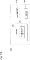
Fig. 13. Fig. 13 is a block diagram showing a construction example of apower supply unit 10a in anaerosol generation device 1 in a different embodiment of the present disclosure. Thepower supply unit 10a comprises acontroller 50a, aphotosensor 17a, and amemory 18a. - For example, the
photosensor 17a and thememory 18a correspond to thephotosensor 17 and thememory 18 in the embodiment of the present disclosure shown inFig. 5 , respectively. Further, for example, thecontroller 50a corresponds to a part of thecontroller 50 in the embodiment of the present disclosure shown inFig. 5 . Especially, for example, the cartridgedetection judging unit 55a corresponds to the cartridgedetection judging unit 55 in the embodiment of the present disclosure shown inFig. 5 . - The
photosensor 17a comprises a pair of a light emitting element and a light receiving element. Thecontroller 50a is constructed to make thephotosensor 17a detect acartridge 200 through operation to make the light emitting element emit light, when thepower supply unit 10a connects to thecartridge 200, and judge the type of thecartridge 200 based on result of detection. - In the above description, power supply units and cartridges of aerosol generation devices and methods for judging types of cartridges according to some embodiments have been explained with reference to the figures. It can be understood that the present disclosure can be implemented as a program for making a processor perform, when the program is executed by the processor, a method for judging the type of a cartridge, or a computer-readable storage medium which stores the program.
- Further, it should be understood that the embodiments and the modification examples, that have been explained above, of the present disclosure are mere examples, and are not those for limiting the scope of the present disclosure. It should be understood that change, addition, modification, and so on with respect to the embodiments can be performed appropriately, without departing from the gist and the scope of the present disclosure. The scope of the present disclosure should not be limited by any of the above-explained embodiments, and should be defined by the scope of the claims and the equivalent thereof.
- 1 ... Aerosol generation device: 10, 10a ... Power supply unit: 11 ... Power supply unit case: 110 ... First rotating connection part: 12 ... Power supply: 14 ... Operation unit: 15 ... Inhalation sensor: 16 ... Voltage sensor: 17, 17a ... Photosensor: 171 ... Light emitting element: 172 ... Light receiving element: 18, 18a ... Memory: 19 ... Physical switch: 45 ... Notifier: 50, 50a ... Controller: 51 ... Aerosol-generation-request detector 51: 52 ... Operation detector: 53 ... Electric power controller: 54 ... Notification controller: 55, 55a ... Cartridge detection judging unit: 80 ... Connection surface: 20 ... Cartridge unit: 27, 27' ... Cartridge case: 27c1, 27c2 ... Convex part: 200, 200'... Cartridge: 200ci, 200c2 ... Concave part: 260 ... Second rotating connection part: 210 ... Connection electrode part: 220 ... Protruding member: 2201, 2202 ... Protrusion: 280 ... Electrode surface: AR1, AR2 ... Protrusion arranging area: 26 ... End cap: 261 ... Anti-slipping member: 30 ... Capsule unit: 310 ... Opening
Claims (20)
- A power supply unit comprising:a light emitting element;a light receiving element; anda controller which makes, through operation that makes the light emitting element emit light, operation for detecting a cartridge be performed when the power supply unit is connected to the cartridge, and judges the type of the cartridge based on result of the detecting.
- The power supply unit as recited in Claim 1, whereinlight emitted toward the light receiving element from the light emitting element is blocked as a result that a protrusion constructed in the cartridge moves between the light emitting element and the light receiving element;the numbers of protrusions of the cartridges are different according to the types of the cartridges, respectively; and result of the detecting comprises the number of times that the light is blocked.
- The power supply unit as recited in Claim 1, whereinsignal strength of light emitted from the light emitting element and received by the light receiving element is adjusted as a result that a protrusion constructed in the cartridge moves between the light emitting element and the light receiving element;the shapes of the protrusions of the cartridges are different according to the types of the cartridges, respectively; and result of the detecting comprises the signal strength of light adjusted through the shape of the protrusion in the cartridge.
- The power supply unit as recited in any one of Claims 1-3, wherein
the light emitting element and the light receiving element are arranged, on a surface whereat the power supply unit is connected to the cartridge in an axial direction, in such a manner that they are positioned along a circumferential direction to face each other. - The power supply unit as recited in any one of Claims 1-4, wherein the controllerstarts operation for detecting the cartridge in response to reception, by the light receiving element, of light having first signal strength, andterminates the operation for detecting the cartridge in response to reception, by the light receiving element, of light having second signal strength.
- The power supply unit as recited in Claim 5, wherein the controller judges, in response to reception of light having third signal strength that is smaller than the first signal strength and the second signal strength, that the light is blocked.
- The power supply unit as recited in any one of Claims 1-6 comprisinga first pair of a light emitting element and a light receiving element and a second pair of a light emitting element and a light receiving element; whereinthe controller judges the type of the cartridge, based on result of the detecting in the first pair of the light emitting element and the light receiving element and result of the detecting in the second pair of the light emitting element and the light receiving element.
- The power supply unit as recited in any one of Claims 1-7 further comprising a physical switch, whereinthe physical switch is pressed by the cartridge when the power supply unit is connected to the cartridge, andthe controller makes the light emitting element start emission of light in response to an event that the physical switch is pressed.
- The power supply unit as recited in Claim 8, wherein
the controller makes the light emitting element terminate emission of light in response to an event that the physical switch is pressed again by the cartridge. - The power supply unit as recited in any one of Claims 1-8, wherein the controller
makes the light emitting element terminate emission of light in response to completion of judgment of the type of the cartridge based on result of the detecting. - The power supply unit as recited in any one of Claims 1-10, wherein the controller judges, when the cartridge is not detected for a predetermined period of time after starting of emission of the light by the light emitting element, that connection of the power supply unit to the cartridge is failed, and makes the light emitting element terminate emission of the light.
- The power supply unit as recited in Claim 11 further comprising a notifier, wherein
the controller makes the notifier notify the failure of connection. - The power supply unit as recited in Claim 12, wherein
the notification of the failure of connection is used to prompt a user to again perform action to connect the power supply unit to the cartridge. - The power supply unit as recited in any one of Claims 1-13, wherein the controller prohibits supplying of electric power to the cartridge in the case that the type of the cartridge cannot be judged.
- The power supply unit as recited in Claim 1, whereinlight from the light emitting element is reflected toward the light receiving element as a result that a protrusion constructed in the cartridge moves in a space close to the light emitting element and the light receiving element;the numbers of protrusions of the cartridges are different according to the types of the cartridges, respectively; and result of the detecting comprises the number of times that the light emitted from the light emitting element is received by the light receiving element.
- A cartridge, which is to be connected to the power supply unit as recited in any one of Claims 1-15, comprising a protruding member, wherein the protruding members are different according to the types, respectively.
- A cartridge for an aerosol generation device, whereinthe cartridge is provided with a protruding member, wherein the protruding members are different according to the types, respectively; andwhen the cartridge is connected to a power supply unit of the aerosol generation device, detection of the protruding member is performed by a photosensor included in the power supply unit, and the type is judged based on result of the detection.
- The cartridge as recited in Claim 17, whereinthe protruding member comprises a number of protrusions, wherein the numbers of protrusions of the cartridges are different according to the types of the cartridges, respectively;when the cartridge is connected to the power supply unit, the protrusion moves between a light emitting element and a light receiving element which are included in the photosensor and accordingly blocks light emitted toward the light receiving element from the light emitting element; andthe type is judged based on the number of times that the light is blocked by the protrusion.
- The cartridge as recited in Claim 17 or 18, whereinthe aerosol generation device comprises a cartridge case which holds the cartridge and is attached to the power supply unit in an axial direction;when viewed from the axial direction, a cross section of the cartridge has a concave shape that corresponds to a convex shape of a cross section of part of a hollow part of the cartridge case; andthe cross section of the cartridge is aligned, in a circumferential direction, with the cross section of the part of the hollow part of the cartridge case, so that said cartridge is inserted in the hollow part of the cartridge case in the axial direction.
- A method for judging the type of a cartridge, comprising steps, that are performed by a power supply unit of an aerosol generation device when the cartridge is connected in an axial direction to the power supply unit, for:activating a photosensor included in the power supply unit;counting the number of times that light emitted toward a light receiving element from the light emitting element in the photosensor is blocked by a protruding member of the cartridge, wherein the light is blocked as a result that a protrusion of the protruding member moves between the light emitting element and the light receiving element in the photosensor during the time when the cartridge is rotated relative to the power supply unit about an axis by a predetermined distance; andjudging the type of the cartridge based on the counted number of times; whereinthe numbers of protrusions in the protruding members of the cartridges are different according to the types of the cartridges, respectively.
Applications Claiming Priority (1)
| Application Number | Priority Date | Filing Date | Title |
|---|---|---|---|
| PCT/JP2020/001792 WO2021149124A1 (en) | 2020-01-21 | 2020-01-21 | Power supply unit and cartridge for aerosol generation device, and method for determining type of cartridge |
Publications (2)
| Publication Number | Publication Date |
|---|---|
| EP4094596A1 true EP4094596A1 (en) | 2022-11-30 |
| EP4094596A4 EP4094596A4 (en) | 2023-11-01 |
Family
ID=76992129
Family Applications (1)
| Application Number | Title | Priority Date | Filing Date |
|---|---|---|---|
| EP20915084.6A Withdrawn EP4094596A4 (en) | 2020-01-21 | 2020-01-21 | Power supply unit and cartridge for aerosol generation device, and method for determining type of cartridge |
Country Status (3)
| Country | Link |
|---|---|
| EP (1) | EP4094596A4 (en) |
| JP (1) | JP7348313B2 (en) |
| WO (1) | WO2021149124A1 (en) |
Family Cites Families (12)
| Publication number | Priority date | Publication date | Assignee | Title |
|---|---|---|---|---|
| EP2201850A1 (en) | 2008-12-24 | 2010-06-30 | Philip Morris Products S.A. | An article including identification information for use in an electrically heated smoking system |
| US8910639B2 (en) * | 2012-09-05 | 2014-12-16 | R. J. Reynolds Tobacco Company | Single-use connector and cartridge for a smoking article and related method |
| KR20210024679A (en) | 2012-09-28 | 2021-03-05 | 셀가드 엘엘씨 | Porous membranes, materials, composites, laminates, textiles and related methods |
| CN203523809U (en) * | 2013-08-15 | 2014-04-09 | 刘秋明 | Electronic cigarette |
| SI3076812T1 (en) * | 2013-12-03 | 2018-06-29 | Philip Morris Products S.A. | Aerosol-generating article and electrically operated system incorporating a taggant |
| RU2700202C2 (en) | 2014-12-16 | 2019-09-13 | Филип Моррис Продактс С.А. | Tobacco sachet for use in tobacco evaporator |
| JP6843760B2 (en) | 2015-04-07 | 2021-03-17 | フィリップ・モーリス・プロダクツ・ソシエテ・アノニム | Aerosol forming substrate sachet, its manufacturing method, and aerosol generator for use with the sachet |
| WO2018050701A1 (en) * | 2016-09-14 | 2018-03-22 | Philip Morris Products S.A. | Aerosol-generating system and method for controlling the same |
| KR102401719B1 (en) * | 2017-03-06 | 2022-05-25 | 니뽄 다바코 산교 가부시키가이샤 | Battery unit, flavor aspirator, method for controlling battery unit, and program |
| JP6919369B2 (en) * | 2017-06-30 | 2021-08-18 | Tdk株式会社 | Electronic cigarette smoking equipment and tobacco cartridges used for this |
| GB201805268D0 (en) * | 2018-03-29 | 2018-05-16 | Nicoventures Trading Ltd | Apaaratus for generating aerosol from an aerosolisable medium, an article of aerosolisable medium and a method of operating an aerosol generating apparatus |
| KR20210022587A (en) * | 2018-06-26 | 2021-03-03 | 제이티 인터내셔널 소시에떼 아노님 | Electronic Cigarette with Optical Vaporization System |
-
2020
- 2020-01-21 JP JP2021572144A patent/JP7348313B2/en active Active
- 2020-01-21 EP EP20915084.6A patent/EP4094596A4/en not_active Withdrawn
- 2020-01-21 WO PCT/JP2020/001792 patent/WO2021149124A1/en active Application Filing
Also Published As
| Publication number | Publication date |
|---|---|
| JPWO2021149124A1 (en) | 2021-07-29 |
| JP7348313B2 (en) | 2023-09-20 |
| WO2021149124A1 (en) | 2021-07-29 |
| EP4094596A4 (en) | 2023-11-01 |
Similar Documents
| Publication | Publication Date | Title |
|---|---|---|
| US11605963B2 (en) | Power supply unit for aerosol inhaler and control method and program of power supply unit for aerosol inhaler | |
| EP3308661B1 (en) | Module for powering an electronic smoking device portion | |
| RU2711465C2 (en) | Specialized integrated circuit for aerosol delivery device | |
| US20200237009A1 (en) | Battery unit, flavor inhaler, method for controlling battery unit, and program | |
| JP6564922B1 (en) | Power supply unit for aerosol inhaler, its control method and control program | |
| US11705744B2 (en) | Battery unit, flavor inhaler, method for controlling battery unit, and program for detecting degradation of a chargeable and dischargeable power supply of a battery unit of a vaporizor | |
| CA3079154C (en) | Inhalation component generation device, system, control method, and program | |
| CN110381757A (en) | Secondary cell for aerosol delivery equipment | |
| KR102511168B1 (en) | External unit for suction component generating device, suction component generating system, method for controlling external unit for suction component generating device, and program | |
| TW202131809A (en) | Electronic aerosol provision system | |
| WO2018055381A1 (en) | Electronic vapour provision system | |
| EP4094596A1 (en) | Power supply unit and cartridge for aerosol generation device, and method for determining type of cartridge | |
| EP4094597A1 (en) | Cartridge and power unit for aerosol generating device, and method for determining cartridge type | |
| EP4094598A1 (en) | Cartridge and power unit for aerosol generating device, and method for determining cartridge type | |
| JP6647441B1 (en) | Power supply unit for aerosol inhaler, control method and control program therefor | |
| WO2022209527A1 (en) | Aerosol generation apparatus | |
| EA041162B1 (en) | BATTERY PACK, DEVICE FOR INHALATION OF FLAVORING SUBSTANCE, BATTERY PACK CONTROL METHOD AND PROGRAM |
Legal Events
| Date | Code | Title | Description |
|---|---|---|---|
| STAA | Information on the status of an ep patent application or granted ep patent |
Free format text: STATUS: THE INTERNATIONAL PUBLICATION HAS BEEN MADE |
|
| PUAI | Public reference made under article 153(3) epc to a published international application that has entered the european phase |
Free format text: ORIGINAL CODE: 0009012 |
|
| STAA | Information on the status of an ep patent application or granted ep patent |
Free format text: STATUS: REQUEST FOR EXAMINATION WAS MADE |
|
| 17P | Request for examination filed |
Effective date: 20220725 |
|
| AK | Designated contracting states |
Kind code of ref document: A1 Designated state(s): AL AT BE BG CH CY CZ DE DK EE ES FI FR GB GR HR HU IE IS IT LI LT LU LV MC MK MT NL NO PL PT RO RS SE SI SK SM TR |
|
| DAV | Request for validation of the european patent (deleted) | ||
| DAX | Request for extension of the european patent (deleted) | ||
| REG | Reference to a national code |
Ref country code: DE Ref legal event code: R079 Free format text: PREVIOUS MAIN CLASS: A24F0040400000 Ipc: A24F0040530000 |
|
| STAA | Information on the status of an ep patent application or granted ep patent |
Free format text: STATUS: THE APPLICATION HAS BEEN WITHDRAWN |
|
| A4 | Supplementary search report drawn up and despatched |
Effective date: 20230928 |
|
| RIC1 | Information provided on ipc code assigned before grant |
Ipc: A24F 40/42 20200101ALN20230922BHEP Ipc: A24F 40/10 20200101ALN20230922BHEP Ipc: A24F 40/51 20200101ALI20230922BHEP Ipc: A24F 40/53 20200101AFI20230922BHEP |
|
| 18W | Application withdrawn |
Effective date: 20231013 |