EP4094142B1 - Elektronische tastatur - Google Patents
Elektronische tastatur Download PDFInfo
- Publication number
- EP4094142B1 EP4094142B1 EP21701565.0A EP21701565A EP4094142B1 EP 4094142 B1 EP4094142 B1 EP 4094142B1 EP 21701565 A EP21701565 A EP 21701565A EP 4094142 B1 EP4094142 B1 EP 4094142B1
- Authority
- EP
- European Patent Office
- Prior art keywords
- pressure sensor
- circuit board
- electronic keyboard
- keyboard
- keys
- Prior art date
- Legal status (The legal status is an assumption and is not a legal conclusion. Google has not performed a legal analysis and makes no representation as to the accuracy of the status listed.)
- Active
Links
Images




Classifications
-
- G—PHYSICS
- G06—COMPUTING OR CALCULATING; COUNTING
- G06F—ELECTRIC DIGITAL DATA PROCESSING
- G06F3/00—Input arrangements for transferring data to be processed into a form capable of being handled by the computer; Output arrangements for transferring data from processing unit to output unit, e.g. interface arrangements
- G06F3/01—Input arrangements or combined input and output arrangements for interaction between user and computer
- G06F3/02—Input arrangements using manually operated switches, e.g. using keyboards or dials
- G06F3/0202—Constructional details or processes of manufacture of the input device
-
- H—ELECTRICITY
- H01—ELECTRIC ELEMENTS
- H01H—ELECTRIC SWITCHES; RELAYS; SELECTORS; EMERGENCY PROTECTIVE DEVICES
- H01H13/00—Switches having rectilinearly-movable operating part or parts adapted for pushing or pulling in one direction only, e.g. push-button switch
- H01H13/70—Switches having rectilinearly-movable operating part or parts adapted for pushing or pulling in one direction only, e.g. push-button switch having a plurality of operating members associated with different sets of contacts, e.g. keyboard
- H01H13/702—Switches having rectilinearly-movable operating part or parts adapted for pushing or pulling in one direction only, e.g. push-button switch having a plurality of operating members associated with different sets of contacts, e.g. keyboard with contacts carried by or formed from layers in a multilayer structure, e.g. membrane switches
- H01H13/705—Switches having rectilinearly-movable operating part or parts adapted for pushing or pulling in one direction only, e.g. push-button switch having a plurality of operating members associated with different sets of contacts, e.g. keyboard with contacts carried by or formed from layers in a multilayer structure, e.g. membrane switches characterised by construction, mounting or arrangement of operating parts, e.g. push-buttons or keys
Definitions
- the present invention relates to an electronic keyboard and an electronic device comprising an electronic keyboard.
- Electronic devices such as personal or desktop computers which utilise electronic keyboards for providing an input into the electronic devices are widely known and are highly utilised in both home and work environments.
- An electronic keyboard of this type provides an instruction and data input device used to operate the electronic device or other equipment.
- a typical keyboard includes a keyboard substrate, a plurality of keys, and a circuit board.
- a user presses the keys so that the circuit board can generate corresponding electrical signals, thereby completing corresponding processing by the corresponding electronic device.
- a signal is only generated when a key is pressed, and the corresponding processing is completed on the corresponding electronic device, which reduces the user's experience and is inconvenient for the user's operation.
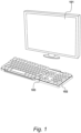
- Figure 1 shows a typical electronic device 101 comprising a keyboard 102 in accordance with an embodiment of the present invention.
- electronic device 101 is a personal computer as shown, and, in an embodiment, game applications are configured to run on the personal computer. Consequently, a keyboard provided in accordance with the present invention allows a user to control the relative actions of a virtual character in such a game by operating keyboard 102 in accordance with the invention.
- a user can press a designated key, such as key 103, with a relatively high applied pressure, or hard key press.
- a designated key such as key 103
- the user can tap designated key 103 lightly at a reduced applied pressure.
- keyboard 102 comprises key 301, circuit board 302, pressing layer 303 and pressure sensor 304.
- pressure sensor 304 is provided between a lower portion 305 of cavity 203 and circuit board 302. Pressing layer 303 is moveably connected to key 301 and circuit board 302 is provided between pressing layer 303 and lower portion 305.
- pressure sensor 304 is electrically connected to circuit board 302, such that a force-receiving surface of pressure sensor 304 is aligned with a projection area 306 of key 301.
- keyboard 102 further comprises a support plate 307 arranged between lower portion 305 and circuit board 302.
- keyboard 102 further comprises a force concentrator 308 which is bonded to circuit board 302 and positioned between circuit board 302 and lower portion 305 of keyboard cavity 203.
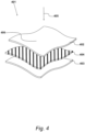
- any of the described pressure sensors herein, such as pressure sensor 304, may be substantially similar to pressure sensor 401 illustrated in Figure 4 .
- pressure sensor 401 is a thin film pressure sensor.
- pressure sensor 401 comprises a first conductive layer 402, a second conductive layer 403 and an intermediate layer 404.
- Intermediate layer 404 is arranged between conductive layer 402 and conductive layer 403.
- conductive layer 402 and conductive layer 403 form an electrical connection and pathway through the layers.
- the layers may be brought into contact with each other by means of an applied force, such as applied force 405, onto a force-receiving surface 406 of pressure sensor 401.
- the contact area between the intermediate layer and the two conductive layer layers is also different, that is, the resistance generated is also different, so that different pressures will produce different resistances.
- the number of keys 103 on keyboard 102 is greater than or equal to the number of pressure sensors 401 on keyboard 102.
- one pressure sensor 304 is provided in the projection area 306 of each key 301 of the plurality of keys 201.
- Figure 5 shows a schematic structural diagram of a longitudinal section of keyboard 102 provided by an embodiment of the present invention.
- Keyboard 102 comprises a plurality of keys 201, a housing 501, a pressing layer 502, a circuit board 503 and at least one pressure sensor 504.
- housing 501 comprises a cavity 203 which is configured to accommodate circuit board 503, pressing layer 502 and at least one pressure sensor 504.
- circuit board 503, pressing layer 502 and the at least one pressure sensor 504 are all arranged in cavity 203.
- the at least one pressure sensor 504 is arranged between a lower portion 505 of cavity 203 and circuit board 503.
- Each pressure sensor 504 is provided with a pressing layer 502 arranged on one side of circuit board 503, and a plurality of keys 201 are movably arranged on pressing layer 502.
- each pressure sensor 504 is connected to circuit board 503, and the force-receiving surface (406) of each pressure sensor 504 is aligned with a projection area 506 of a corresponding key 201.
- lower portion 505 of housing 501 has a certain thickness and comprises at least one placement slot 507 which is provided in lower portion 505 facing circuit board 503.
- the position of each placement slot 507 corresponds to the projection area of a corresponding key 506.
- Each placement slot 507 is utilised for positioning each pressure sensor 504.
- the cross-sectional area of each placement slot 507 is slightly larger than that of its corresponding pressure sensor 504.
- the depth of each placement slot 507 and the thickness of its corresponding pressure sensor 504 may be substantially similar.
- circuit board 503 receives a signal in response to the user's applied press.
- each pressure sensor 504 can detect a pressure signal and transmit this pressure signal to circuit board 503.
- Circuit board 503 can then transmit a contact signal to an electronic device, such as electronic device 101 of Figure 1 .
- the electronic device is configured to receive an input signal and a pressure signal such that the electronic device can perform corresponding processing in accordance with the contact signal and pressure signal.
- pressure sensor 504 By positioning pressure sensor 504 between lower portion 505 of cavity 203 and circuit board 503, pressure sensor 504 can be electrically connected to circuit board 503, and the corresponding pressure signal can be generated according to the pressure applied by a user pressing a key. In this way, the corresponding processing can be completed on the corresponding electronic device thereby improving the user experience and facilitating user operations.
- FIG. 6 A schematic diagram of a longitudinal cross-sectional structure of a key 201 and pressing layer 502 provided by the embodiment of the present invention of Figure 5 is shown in Figure 6 .
- pressing layer 502 is provided with a plurality of grooves 601.
- Each groove 601 is provided with a key 201, which is moveable within its respective groove 601.
- the number of grooves 601 and the number of keys 201 are substantially similar, and the area where the groove 601 is located overlaps and falls within the projection area of a corresponding key 201.
- each key 201 includes a connecting portion 602, and connecting portion 602 is disposed to the side of key 201 closest to pressing layer 502.
- the cross-sectional area of each connecting portion 602 is slightly smaller than the cross-sectional area of its corresponding groove 601.
- the cross-sectional area of the connecting portion 602 and the cross-sectional area of its corresponding groove 601 is substantially similar.
- connection between each groove 601 and pressing layer 502 is a detachable connection.
- the detachable connection is a snap connection.
- pressing layer 502 comprises an elastic material.
- FIG. 7 A schematic longitudinal cross-sectional structure diagram of a keyboard in accordance with an alternative embodiment of the present invention is shown in Figure 7 .
- keyboard 102 comprises a support plate 701 arranged between the lower portion 702 of keyboard 102 and a circuit board 703.
- Support plate 701 is provided with at least one placement slot on a first side which faces circuit board 703.
- a pressure sensor is provided in each placement slot.
- support plate 701 has a thickness and the cross-sectional area of support plate 701, circuit board 703 and pressing layer 704 are substantially similar. Additionally, the cross-sectional shape of support plate 701, circuit board 703 and pressing layer 704 are also substantially similar.
- FIG. 8 A longitudinal section structural diagram of a support plate 701 and a circuit board 703 in accordance with the embodiment of Figure 7 is shown in Figure 8 .
- support plate 701 is provided with at least one placement slot 801 on a first side 802 of the support plate 701 which faces circuit board 703.
- a pressure sensor 803 is provided in each placement slot 801.
- each placement slot 801 may be square, circular, or any other suitable geometric figure, which is not specifically limited in the embodiments of the present invention.
- support plate 701 is provided with three placement slots 801.
- a pressure sensor 802 is placed in each placement slot 801.
- the projection area of each key 201 of keyboard 102 aligns with a corresponding placement slot 801.
- the projection area of a first key coincides with a first placement slot
- the projection area of a second key coincides with a second placement slot
- the projection area of a third key coincides with a third placement slot.
- keyboard 102 further comprises at least one force concentrator 804.
- each placement slot 801 is provided with a force concentrator 804, and each force concentrator 804 is located between each pressure sensor 803 and circuit board 703.
- force concentrator 804 is bonded to circuit board 703.
- pressing layer 704 is brought into contact with circuit board 703.
- the applied pressure acts on circuit board 703, before transmitting through circuit board 703 and acting on force concentrator 804.
- Force concentrator 804 transmits the applied pressure to pressure sensor 803 such that pressure sensor 803 is able to detect the applied pressure.
- the cross-sectional area of force concentrator 804 and the cross-sectional area of pressure sensor 803 are substantially similar.
- the cross-sectional area of force concentrator 804 is larger than the cross-sectional area of pressure sensor 803 and smaller than the cross-sectional area of placement slot 801. It is appreciated that in further embodiments, any suitable variation in cross-sectional area or size may be utilised to suit the specific application.
- force concentrator 804 comprises a polyester resin material such as PET (polyethylene terephthalate).
- PET polyethylene terephthalate
- force concentrator 804 may comprise any other alternative material which facilitates the concentration of pressure.
- the total thickness of each pressure sensor 803 and its corresponding force concentrator 804 together is substantially similar to the depth of placement slot 801. It is noted that if the thickness of placement slot 801 is represented as a, the total thickness of pressure sensor 803 and force concentrator 804 together is represented as b , the difference between a and b can be determined as falling within a pre-set size range.
- the present invention therefore provides an improvement over the prior art for the following reasons at least. Firstly, in the prior art of record, a signal generated from the keyboard is only generated when a key on the keyboard is actually pressed and is further only processed by the connected electronic device. The additional processing required in this case provides added inconvenience and a reduction in the user experience.
- the pressure sensor By positioning a pressure sensor between the bottom of the keyboard accommodating cavity and the circuit board, the pressure sensor is electrically connected to the circuit board, meaning the corresponding pressure signal can be generated according to a pressure applied by a user pressing the key in question.
- the corresponding processing can be completed on the corresponding electronic device.
Landscapes
- Engineering & Computer Science (AREA)
- General Engineering & Computer Science (AREA)
- Theoretical Computer Science (AREA)
- Human Computer Interaction (AREA)
- Physics & Mathematics (AREA)
- General Physics & Mathematics (AREA)
- Input From Keyboards Or The Like (AREA)
- Push-Button Switches (AREA)
Claims (11)
- Eine elektronische Tastatur (102), das Folgende umfasst:eine Vielzahl von Tasten (201, 301); undein Gehäuse (501) mit einem Hohlraum (203);wobei der Hohlraum eine Leiterplatte (302, 503, 703), eine Pressschicht (303, 502, 704) und mindestens einen in dem Hohlraum angeordneten Drucksensor (304, 504, 803) aufnimmt;wobei der mindestens eine Drucksensor zwischen einem unteren Abschnitt (305, 505, 702) des Hohlraums und der Leiterplatte vorgesehen ist;die Pressschicht beweglich mit jeder der Vielzahl von Tasten verbunden ist und die Leiterplatte zwischen der Pressschicht und dem unteren Abschnitt vorgesehen ist; undder mindestens eine Drucksensor mit der Leiterplatte verbunden ist und eine Kraftempfangsfläche (406) jedes der mindestens einen Drucksensoren mit einem Projektionsbereich (306) der entsprechenden der Vielzahl von Tasten ausgerichtet ist; dadurch gekennzeichnet, dass:die elektronische Tastatur ferner eine Trägerplatte (307, 701) umfasst, die zwischen dem unteren Abschnitt des Hohlraums und der Leiterplatte angeordnet ist; und die Trägerplatte mindestens einen Platzierungsschlitz (507, 801) auf einer ersten Seite (802) umfasst, die der Leiterplatte zugewandt ist, wobei jeder der mindestens einen Platzierungsschlitze einen der mindestens einen Drucksensoren enthält, die darin angeordnet sind.
- Eine elektronische Tastatur nach Anspruch 1, wobei eine Vielzahl von Rillen (601) auf der Pressschicht vorgesehen ist.
- Eine elektronische Tastatur nach Anspruch 2, wobei jede der mehreren Tasten beweglich in einer entsprechenden der mehreren Nuten aufgenommen ist.
- Eine elektronische Tastatur nach einem der Ansprüche 1 bis 3, die ferner Folgendes umfasst:
mindestens einen Kraftkonzentrator (308, 804), der so konfiguriert ist, dass er einen ausgeübten Druck auf den Drucksensor überträgt, und der zwischen dem mindestens einen Drucksensor und der Leiterplatte angeordnet ist. - Eine elektronische Tastatur nach Anspruch 4, wobei jeder Kraftkonzentrator in einem entsprechenden, mindestens einen Platzierungsschlitz angeordnet ist.
- Eine elektronische Tastatur nach Anspruch 4 oder Anspruch 5, wobei der mindestens eine Drucksensor eine erste Dicke und der Kraftkonzentrator eine zweite Dicke aufweist und die Summe (b) der ersten Dicke und der zweiten Dicke im Wesentlichen einer Tiefe (a) des Platzierungsschlitzes entspricht.
- Eine elektronische Tastatur nach einem der Ansprüche 4 bis 6, wobei der Kraftkonzentrator aus einem Polyesterharzmaterial besteht.
- Eine elektronische Tastatur nach einem der vorhergehenden Ansprüche, wobei der mindestens eine Drucksensor ein Dünnfilm-Drucksensor ist.
- Eine elektronische Tastatur nach einem der vorhergehenden Ansprüche, wobei die Anzahl der Tasten größer oder gleich der Anzahl mindestens eines der Drucksensoren ist.
- Eine elektronische Tastatur nach einem der vorhergehenden Ansprüche, wobei die Pressschicht aus einem elastischen Material besteht.
- Ein elektronisches Gerät (101), das die elektronische Tastatur nach einem der vorhergehenden Ansprüche umfasst.
Applications Claiming Priority (2)
| Application Number | Priority Date | Filing Date | Title |
|---|---|---|---|
| CN202020132796.7U CN210864642U (zh) | 2020-01-20 | 2020-01-20 | 一种键盘及电子设备 |
| PCT/GB2021/000003 WO2021148770A1 (en) | 2020-01-20 | 2021-01-19 | Electronic keyboard |
Publications (2)
| Publication Number | Publication Date |
|---|---|
| EP4094142A1 EP4094142A1 (de) | 2022-11-30 |
| EP4094142B1 true EP4094142B1 (de) | 2025-06-04 |
Family
ID=71293570
Family Applications (1)
| Application Number | Title | Priority Date | Filing Date |
|---|---|---|---|
| EP21701565.0A Active EP4094142B1 (de) | 2020-01-20 | 2021-01-19 | Elektronische tastatur |
Country Status (6)
| Country | Link |
|---|---|
| US (1) | US12032749B2 (de) |
| EP (1) | EP4094142B1 (de) |
| JP (1) | JP7749565B2 (de) |
| KR (1) | KR20220150291A (de) |
| CN (1) | CN210864642U (de) |
| WO (1) | WO2021148770A1 (de) |
Citations (1)
| Publication number | Priority date | Publication date | Assignee | Title |
|---|---|---|---|---|
| US9465412B2 (en) * | 2012-03-02 | 2016-10-11 | Microsoft Technology Licensing, Llc | Input device layers and nesting |
Family Cites Families (13)
| Publication number | Priority date | Publication date | Assignee | Title |
|---|---|---|---|---|
| JPS5886628A (ja) * | 1981-11-18 | 1983-05-24 | Matsushita Electric Ind Co Ltd | キ−ボ−ドスイツチ装置 |
| JP2830101B2 (ja) * | 1988-12-28 | 1998-12-02 | カシオ計算機株式会社 | 電子鍵盤楽器の鍵盤装置 |
| JP4573890B2 (ja) * | 2008-08-25 | 2010-11-04 | 信越ポリマー株式会社 | 入力装置およびその入力装置を用いた電子機器 |
| US9246487B2 (en) * | 2008-12-16 | 2016-01-26 | Dell Products Lp | Keyboard with user configurable granularity scales for pressure sensitive keys |
| TW201205626A (en) * | 2010-07-30 | 2012-02-01 | Primax Electronics Ltd | Dual force sensing keyboard |
| US8789186B2 (en) * | 2011-03-03 | 2014-07-22 | Jpmorgan Chase Bank, N.A. | System and method for packet profiling |
| US20120228109A1 (en) * | 2011-03-08 | 2012-09-13 | Ibiden Co., Ltd. | Sensor, keyboard and method for manufacturing sensor |
| US9122315B2 (en) * | 2011-12-06 | 2015-09-01 | Blackberry Limited | Expandable keyboard |
| US20140218278A1 (en) * | 2013-02-07 | 2014-08-07 | Htc Corporation | Portable device and operation method therefor |
| KR102432009B1 (ko) * | 2015-09-03 | 2022-08-12 | 엘지이노텍 주식회사 | 압력 센서 |
| TWI623953B (zh) * | 2016-10-28 | 2018-05-11 | 致伸科技股份有限公司 | 鍵盤 |
| CN106356229B (zh) * | 2016-11-22 | 2019-09-03 | 珠海安润普科技有限公司 | 柔性压力开关 |
| GB2576610B (en) * | 2018-08-07 | 2021-12-15 | Sonuus Ltd | Electronic drums |
-
2020
- 2020-01-20 CN CN202020132796.7U patent/CN210864642U/zh active Active
-
2021
- 2021-01-19 KR KR1020227028842A patent/KR20220150291A/ko not_active Ceased
- 2021-01-19 WO PCT/GB2021/000003 patent/WO2021148770A1/en not_active Ceased
- 2021-01-19 EP EP21701565.0A patent/EP4094142B1/de active Active
- 2021-01-19 US US17/794,132 patent/US12032749B2/en active Active
- 2021-01-19 JP JP2022544203A patent/JP7749565B2/ja active Active
Patent Citations (1)
| Publication number | Priority date | Publication date | Assignee | Title |
|---|---|---|---|---|
| US9465412B2 (en) * | 2012-03-02 | 2016-10-11 | Microsoft Technology Licensing, Llc | Input device layers and nesting |
Also Published As
| Publication number | Publication date |
|---|---|
| JP2023517448A (ja) | 2023-04-26 |
| KR20220150291A (ko) | 2022-11-10 |
| EP4094142A1 (de) | 2022-11-30 |
| JP7749565B2 (ja) | 2025-10-06 |
| WO2021148770A1 (en) | 2021-07-29 |
| US20230350500A1 (en) | 2023-11-02 |
| US12032749B2 (en) | 2024-07-09 |
| CN210864642U (zh) | 2020-06-26 |
Similar Documents
| Publication | Publication Date | Title |
|---|---|---|
| US6445382B1 (en) | Keyboard with integrated pointing stick cable | |
| US10963087B2 (en) | Pressure sensitive keys | |
| US9454239B2 (en) | Enabling touch events on a touch sensitive mechanical keyboard | |
| US20130342465A1 (en) | Interchangeable Surface Translation and Force Concentration | |
| US20130300590A1 (en) | Audio Feedback | |
| US20130346636A1 (en) | Interchangeable Surface Input Device Mapping | |
| US20130342464A1 (en) | Input Device with Interchangeable Surface | |
| US20100300772A1 (en) | Depressable touch sensor | |
| US11829567B2 (en) | Touch pad, force touch apparatus, and electronic device | |
| US12032749B2 (en) | Electronic keyboard | |
| TWI925502B (zh) | 疊加型觸控鍵盤裝置及其觸控感應模組 |
Legal Events
| Date | Code | Title | Description |
|---|---|---|---|
| STAA | Information on the status of an ep patent application or granted ep patent |
Free format text: STATUS: UNKNOWN |
|
| STAA | Information on the status of an ep patent application or granted ep patent |
Free format text: STATUS: THE INTERNATIONAL PUBLICATION HAS BEEN MADE |
|
| PUAI | Public reference made under article 153(3) epc to a published international application that has entered the european phase |
Free format text: ORIGINAL CODE: 0009012 |
|
| STAA | Information on the status of an ep patent application or granted ep patent |
Free format text: STATUS: REQUEST FOR EXAMINATION WAS MADE |
|
| 17P | Request for examination filed |
Effective date: 20220817 |
|
| AK | Designated contracting states |
Kind code of ref document: A1 Designated state(s): AL AT BE BG CH CY CZ DE DK EE ES FI FR GB GR HR HU IE IS IT LI LT LU LV MC MK MT NL NO PL PT RO RS SE SI SK SM TR |
|
| DAV | Request for validation of the european patent (deleted) | ||
| DAX | Request for extension of the european patent (deleted) | ||
| RAP3 | Party data changed (applicant data changed or rights of an application transferred) |
Owner name: PERATECH HOLDCO LTD |
|
| RAP1 | Party data changed (applicant data changed or rights of an application transferred) |
Owner name: PERATECH IP LTD |
|
| GRAP | Despatch of communication of intention to grant a patent |
Free format text: ORIGINAL CODE: EPIDOSNIGR1 |
|
| STAA | Information on the status of an ep patent application or granted ep patent |
Free format text: STATUS: GRANT OF PATENT IS INTENDED |
|
| INTG | Intention to grant announced |
Effective date: 20250107 |
|
| 111L | Licence recorded |
Designated state(s): AL AT BE BG CH CY CZ DE DK EE ES FI FR GB GR HR HU IE IS IT LT LU LV MC MK MT NL NO PL PT RO RS SE SI SK SM TR Free format text: EXCLUSIVE LICENSE Name of requester: PERATECH HOLDCO LTD, GB Effective date: 20240822 |
|
| GRAS | Grant fee paid |
Free format text: ORIGINAL CODE: EPIDOSNIGR3 |
|
| GRAA | (expected) grant |
Free format text: ORIGINAL CODE: 0009210 |
|
| STAA | Information on the status of an ep patent application or granted ep patent |
Free format text: STATUS: THE PATENT HAS BEEN GRANTED |
|
| 111L | Licence recorded |
Designated state(s): AL AT BE BG CH CY CZ DE DK EE ES FI FR GB GR HR HU IE IS IT LT LU LV MC MK MT NL NO PL PT RO RS SE SI SK SM TR Free format text: EXCLUSIVE LICENSE Name of requester: PERATECH HOLDCO LTD, GB Effective date: 20240822 |
|
| AK | Designated contracting states |
Kind code of ref document: B1 Designated state(s): AL AT BE BG CH CY CZ DE DK EE ES FI FR GB GR HR HU IE IS IT LI LT LU LV MC MK MT NL NO PL PT RO RS SE SI SK SM TR |
|
| REG | Reference to a national code |
Ref country code: GB Ref legal event code: FG4D |
|
| REG | Reference to a national code |
Ref country code: CH Ref legal event code: EP |
|
| REG | Reference to a national code |
Ref country code: DE Ref legal event code: R096 Ref document number: 602021031718 Country of ref document: DE |
|
| REG | Reference to a national code |
Ref country code: IE Ref legal event code: FG4D |
|
| REG | Reference to a national code |
Ref country code: NL Ref legal event code: MP Effective date: 20250604 |
|
| PG25 | Lapsed in a contracting state [announced via postgrant information from national office to epo] |
Ref country code: FI Free format text: LAPSE BECAUSE OF FAILURE TO SUBMIT A TRANSLATION OF THE DESCRIPTION OR TO PAY THE FEE WITHIN THE PRESCRIBED TIME-LIMIT Effective date: 20250604 Ref country code: ES Free format text: LAPSE BECAUSE OF FAILURE TO SUBMIT A TRANSLATION OF THE DESCRIPTION OR TO PAY THE FEE WITHIN THE PRESCRIBED TIME-LIMIT Effective date: 20250604 |
|
| REG | Reference to a national code |
Ref country code: LT Ref legal event code: MG9D |
|
| PG25 | Lapsed in a contracting state [announced via postgrant information from national office to epo] |
Ref country code: NO Free format text: LAPSE BECAUSE OF FAILURE TO SUBMIT A TRANSLATION OF THE DESCRIPTION OR TO PAY THE FEE WITHIN THE PRESCRIBED TIME-LIMIT Effective date: 20250904 Ref country code: GR Free format text: LAPSE BECAUSE OF FAILURE TO SUBMIT A TRANSLATION OF THE DESCRIPTION OR TO PAY THE FEE WITHIN THE PRESCRIBED TIME-LIMIT Effective date: 20250905 |
|
| PG25 | Lapsed in a contracting state [announced via postgrant information from national office to epo] |
Ref country code: PL Free format text: LAPSE BECAUSE OF FAILURE TO SUBMIT A TRANSLATION OF THE DESCRIPTION OR TO PAY THE FEE WITHIN THE PRESCRIBED TIME-LIMIT Effective date: 20250604 |
|
| PG25 | Lapsed in a contracting state [announced via postgrant information from national office to epo] |
Ref country code: BG Free format text: LAPSE BECAUSE OF FAILURE TO SUBMIT A TRANSLATION OF THE DESCRIPTION OR TO PAY THE FEE WITHIN THE PRESCRIBED TIME-LIMIT Effective date: 20250604 |
|
| PG25 | Lapsed in a contracting state [announced via postgrant information from national office to epo] |
Ref country code: HR Free format text: LAPSE BECAUSE OF FAILURE TO SUBMIT A TRANSLATION OF THE DESCRIPTION OR TO PAY THE FEE WITHIN THE PRESCRIBED TIME-LIMIT Effective date: 20250604 |
|
| PG25 | Lapsed in a contracting state [announced via postgrant information from national office to epo] |
Ref country code: RS Free format text: LAPSE BECAUSE OF FAILURE TO SUBMIT A TRANSLATION OF THE DESCRIPTION OR TO PAY THE FEE WITHIN THE PRESCRIBED TIME-LIMIT Effective date: 20250904 |
|
| PG25 | Lapsed in a contracting state [announced via postgrant information from national office to epo] |
Ref country code: LV Free format text: LAPSE BECAUSE OF FAILURE TO SUBMIT A TRANSLATION OF THE DESCRIPTION OR TO PAY THE FEE WITHIN THE PRESCRIBED TIME-LIMIT Effective date: 20250604 |
|
| PG25 | Lapsed in a contracting state [announced via postgrant information from national office to epo] |
Ref country code: NL Free format text: LAPSE BECAUSE OF FAILURE TO SUBMIT A TRANSLATION OF THE DESCRIPTION OR TO PAY THE FEE WITHIN THE PRESCRIBED TIME-LIMIT Effective date: 20250604 |
|
| PG25 | Lapsed in a contracting state [announced via postgrant information from national office to epo] |
Ref country code: PT Free format text: LAPSE BECAUSE OF FAILURE TO SUBMIT A TRANSLATION OF THE DESCRIPTION OR TO PAY THE FEE WITHIN THE PRESCRIBED TIME-LIMIT Effective date: 20251006 |
|
| REG | Reference to a national code |
Ref country code: AT Ref legal event code: MK05 Ref document number: 1800963 Country of ref document: AT Kind code of ref document: T Effective date: 20250604 |
|
| PG25 | Lapsed in a contracting state [announced via postgrant information from national office to epo] |
Ref country code: IS Free format text: LAPSE BECAUSE OF FAILURE TO SUBMIT A TRANSLATION OF THE DESCRIPTION OR TO PAY THE FEE WITHIN THE PRESCRIBED TIME-LIMIT Effective date: 20251004 |
|
| PG25 | Lapsed in a contracting state [announced via postgrant information from national office to epo] |
Ref country code: AT Free format text: LAPSE BECAUSE OF FAILURE TO SUBMIT A TRANSLATION OF THE DESCRIPTION OR TO PAY THE FEE WITHIN THE PRESCRIBED TIME-LIMIT Effective date: 20250604 Ref country code: SM Free format text: LAPSE BECAUSE OF FAILURE TO SUBMIT A TRANSLATION OF THE DESCRIPTION OR TO PAY THE FEE WITHIN THE PRESCRIBED TIME-LIMIT Effective date: 20250604 |
|
| PG25 | Lapsed in a contracting state [announced via postgrant information from national office to epo] |
Ref country code: CZ Free format text: LAPSE BECAUSE OF FAILURE TO SUBMIT A TRANSLATION OF THE DESCRIPTION OR TO PAY THE FEE WITHIN THE PRESCRIBED TIME-LIMIT Effective date: 20250604 |
|
| PG25 | Lapsed in a contracting state [announced via postgrant information from national office to epo] |
Ref country code: EE Free format text: LAPSE BECAUSE OF FAILURE TO SUBMIT A TRANSLATION OF THE DESCRIPTION OR TO PAY THE FEE WITHIN THE PRESCRIBED TIME-LIMIT Effective date: 20250604 |
|
| PG25 | Lapsed in a contracting state [announced via postgrant information from national office to epo] |
Ref country code: SK Free format text: LAPSE BECAUSE OF FAILURE TO SUBMIT A TRANSLATION OF THE DESCRIPTION OR TO PAY THE FEE WITHIN THE PRESCRIBED TIME-LIMIT Effective date: 20250604 |
|
| PG25 | Lapsed in a contracting state [announced via postgrant information from national office to epo] |
Ref country code: IT Free format text: LAPSE BECAUSE OF FAILURE TO SUBMIT A TRANSLATION OF THE DESCRIPTION OR TO PAY THE FEE WITHIN THE PRESCRIBED TIME-LIMIT Effective date: 20250604 |
|
| REG | Reference to a national code |
Ref country code: DE Ref legal event code: R097 Ref document number: 602021031718 Country of ref document: DE |
|
| PLBE | No opposition filed within time limit |
Free format text: ORIGINAL CODE: 0009261 |
|
| STAA | Information on the status of an ep patent application or granted ep patent |
Free format text: STATUS: NO OPPOSITION FILED WITHIN TIME LIMIT |
|
| PG25 | Lapsed in a contracting state [announced via postgrant information from national office to epo] |
Ref country code: DK Free format text: LAPSE BECAUSE OF FAILURE TO SUBMIT A TRANSLATION OF THE DESCRIPTION OR TO PAY THE FEE WITHIN THE PRESCRIBED TIME-LIMIT Effective date: 20250604 |
|
| REG | Reference to a national code |
Ref country code: CH Ref legal event code: L10 Free format text: ST27 STATUS EVENT CODE: U-0-0-L10-L00 (AS PROVIDED BY THE NATIONAL OFFICE) Effective date: 20260416 |
|
| 26N | No opposition filed |
Effective date: 20260305 |