EP4094086B1 - Auf wahrscheinlichkeit basierende akustische positionierung - Google Patents
Auf wahrscheinlichkeit basierende akustische positionierung Download PDFInfo
- Publication number
- EP4094086B1 EP4094086B1 EP21701304.4A EP21701304A EP4094086B1 EP 4094086 B1 EP4094086 B1 EP 4094086B1 EP 21701304 A EP21701304 A EP 21701304A EP 4094086 B1 EP4094086 B1 EP 4094086B1
- Authority
- EP
- European Patent Office
- Prior art keywords
- acoustic
- mobile device
- acoustic transmitter
- transmitter units
- position estimate
- Prior art date
- Legal status (The legal status is an assumption and is not a legal conclusion. Google has not performed a legal analysis and makes no representation as to the accuracy of the status listed.)
- Active
Links
Images


Classifications
-
- G—PHYSICS
- G01—MEASURING; TESTING
- G01S—RADIO DIRECTION-FINDING; RADIO NAVIGATION; DETERMINING DISTANCE OR VELOCITY BY USE OF RADIO WAVES; LOCATING OR PRESENCE-DETECTING BY USE OF THE REFLECTION OR RERADIATION OF RADIO WAVES; ANALOGOUS ARRANGEMENTS USING OTHER WAVES
- G01S5/00—Position-fixing by co-ordinating two or more direction or position line determinations; Position-fixing by co-ordinating two or more distance determinations
- G01S5/01—Determining conditions which influence positioning, e.g. radio environment, state of motion or energy consumption
- G01S5/018—Involving non-radio wave signals or measurements
-
- G—PHYSICS
- G01—MEASURING; TESTING
- G01S—RADIO DIRECTION-FINDING; RADIO NAVIGATION; DETERMINING DISTANCE OR VELOCITY BY USE OF RADIO WAVES; LOCATING OR PRESENCE-DETECTING BY USE OF THE REFLECTION OR RERADIATION OF RADIO WAVES; ANALOGOUS ARRANGEMENTS USING OTHER WAVES
- G01S11/00—Systems for determining distance or velocity not using reflection or reradiation
- G01S11/14—Systems for determining distance or velocity not using reflection or reradiation using ultrasonic, sonic or infrasonic waves
-
- G—PHYSICS
- G01—MEASURING; TESTING
- G01S—RADIO DIRECTION-FINDING; RADIO NAVIGATION; DETERMINING DISTANCE OR VELOCITY BY USE OF RADIO WAVES; LOCATING OR PRESENCE-DETECTING BY USE OF THE REFLECTION OR RERADIATION OF RADIO WAVES; ANALOGOUS ARRANGEMENTS USING OTHER WAVES
- G01S5/00—Position-fixing by co-ordinating two or more direction or position line determinations; Position-fixing by co-ordinating two or more distance determinations
- G01S5/02—Position-fixing by co-ordinating two or more direction or position line determinations; Position-fixing by co-ordinating two or more distance determinations using radio waves
- G01S5/0257—Hybrid positioning
- G01S5/0258—Hybrid positioning by combining or switching between measurements derived from different systems
- G01S5/02585—Hybrid positioning by combining or switching between measurements derived from different systems at least one of the measurements being a non-radio measurement
-
- G—PHYSICS
- G01—MEASURING; TESTING
- G01S—RADIO DIRECTION-FINDING; RADIO NAVIGATION; DETERMINING DISTANCE OR VELOCITY BY USE OF RADIO WAVES; LOCATING OR PRESENCE-DETECTING BY USE OF THE REFLECTION OR RERADIATION OF RADIO WAVES; ANALOGOUS ARRANGEMENTS USING OTHER WAVES
- G01S5/00—Position-fixing by co-ordinating two or more direction or position line determinations; Position-fixing by co-ordinating two or more distance determinations
- G01S5/02—Position-fixing by co-ordinating two or more direction or position line determinations; Position-fixing by co-ordinating two or more distance determinations using radio waves
- G01S5/0257—Hybrid positioning
- G01S5/0263—Hybrid positioning by combining or switching between positions derived from two or more separate positioning systems
- G01S5/0264—Hybrid positioning by combining or switching between positions derived from two or more separate positioning systems at least one of the systems being a non-radio wave positioning system
-
- G—PHYSICS
- G01—MEASURING; TESTING
- G01S—RADIO DIRECTION-FINDING; RADIO NAVIGATION; DETERMINING DISTANCE OR VELOCITY BY USE OF RADIO WAVES; LOCATING OR PRESENCE-DETECTING BY USE OF THE REFLECTION OR RERADIATION OF RADIO WAVES; ANALOGOUS ARRANGEMENTS USING OTHER WAVES
- G01S5/00—Position-fixing by co-ordinating two or more direction or position line determinations; Position-fixing by co-ordinating two or more distance determinations
- G01S5/02—Position-fixing by co-ordinating two or more direction or position line determinations; Position-fixing by co-ordinating two or more distance determinations using radio waves
- G01S5/0257—Hybrid positioning
- G01S5/0268—Hybrid positioning by deriving positions from different combinations of signals or of estimated positions in a single positioning system
-
- G—PHYSICS
- G01—MEASURING; TESTING
- G01S—RADIO DIRECTION-FINDING; RADIO NAVIGATION; DETERMINING DISTANCE OR VELOCITY BY USE OF RADIO WAVES; LOCATING OR PRESENCE-DETECTING BY USE OF THE REFLECTION OR RERADIATION OF RADIO WAVES; ANALOGOUS ARRANGEMENTS USING OTHER WAVES
- G01S5/00—Position-fixing by co-ordinating two or more direction or position line determinations; Position-fixing by co-ordinating two or more distance determinations
- G01S5/18—Position-fixing by co-ordinating two or more direction or position line determinations; Position-fixing by co-ordinating two or more distance determinations using ultrasonic, sonic or infrasonic waves
-
- G—PHYSICS
- G01—MEASURING; TESTING
- G01S—RADIO DIRECTION-FINDING; RADIO NAVIGATION; DETERMINING DISTANCE OR VELOCITY BY USE OF RADIO WAVES; LOCATING OR PRESENCE-DETECTING BY USE OF THE REFLECTION OR RERADIATION OF RADIO WAVES; ANALOGOUS ARRANGEMENTS USING OTHER WAVES
- G01S5/00—Position-fixing by co-ordinating two or more direction or position line determinations; Position-fixing by co-ordinating two or more distance determinations
- G01S5/18—Position-fixing by co-ordinating two or more direction or position line determinations; Position-fixing by co-ordinating two or more distance determinations using ultrasonic, sonic or infrasonic waves
- G01S5/26—Position of receiver fixed by co-ordinating a plurality of position lines defined by path-difference measurements
-
- G—PHYSICS
- G01—MEASURING; TESTING
- G01S—RADIO DIRECTION-FINDING; RADIO NAVIGATION; DETERMINING DISTANCE OR VELOCITY BY USE OF RADIO WAVES; LOCATING OR PRESENCE-DETECTING BY USE OF THE REFLECTION OR RERADIATION OF RADIO WAVES; ANALOGOUS ARRANGEMENTS USING OTHER WAVES
- G01S5/00—Position-fixing by co-ordinating two or more direction or position line determinations; Position-fixing by co-ordinating two or more distance determinations
- G01S5/18—Position-fixing by co-ordinating two or more direction or position line determinations; Position-fixing by co-ordinating two or more distance determinations using ultrasonic, sonic or infrasonic waves
- G01S5/30—Determining absolute distances from a plurality of spaced points of known location
-
- G—PHYSICS
- G01—MEASURING; TESTING
- G01S—RADIO DIRECTION-FINDING; RADIO NAVIGATION; DETERMINING DISTANCE OR VELOCITY BY USE OF RADIO WAVES; LOCATING OR PRESENCE-DETECTING BY USE OF THE REFLECTION OR RERADIATION OF RADIO WAVES; ANALOGOUS ARRANGEMENTS USING OTHER WAVES
- G01S2201/00—Indexing scheme relating to beacons or beacon systems transmitting signals capable of being detected by non-directional receivers and defining directions, positions, or position lines fixed relatively to the beacon transmitters
- G01S2201/01—Indexing scheme relating to beacons or beacon systems transmitting signals capable of being detected by non-directional receivers and defining directions, positions, or position lines fixed relatively to the beacon transmitters adapted for specific applications or environments
- G01S2201/02—Indoor positioning, e.g. in covered car-parks, mining facilities, warehouses
-
- G—PHYSICS
- G01—MEASURING; TESTING
- G01S—RADIO DIRECTION-FINDING; RADIO NAVIGATION; DETERMINING DISTANCE OR VELOCITY BY USE OF RADIO WAVES; LOCATING OR PRESENCE-DETECTING BY USE OF THE REFLECTION OR RERADIATION OF RADIO WAVES; ANALOGOUS ARRANGEMENTS USING OTHER WAVES
- G01S2205/00—Position-fixing by co-ordinating two or more direction or position line determinations; Position-fixing by co-ordinating two or more distance determinations
- G01S2205/01—Position-fixing by co-ordinating two or more direction or position line determinations; Position-fixing by co-ordinating two or more distance determinations specially adapted for specific applications
- G01S2205/02—Indoor
-
- G—PHYSICS
- G01—MEASURING; TESTING
- G01S—RADIO DIRECTION-FINDING; RADIO NAVIGATION; DETERMINING DISTANCE OR VELOCITY BY USE OF RADIO WAVES; LOCATING OR PRESENCE-DETECTING BY USE OF THE REFLECTION OR RERADIATION OF RADIO WAVES; ANALOGOUS ARRANGEMENTS USING OTHER WAVES
- G01S5/00—Position-fixing by co-ordinating two or more direction or position line determinations; Position-fixing by co-ordinating two or more distance determinations
- G01S5/0009—Transmission of position information to remote stations
- G01S5/0018—Transmission from mobile station to base station
- G01S5/0027—Transmission from mobile station to base station of actual mobile position, i.e. position determined on mobile
Definitions
- signals such as ultrasonic signals
- the signals encode identifiers of the respective transmitters units.
- These signals are received by the mobile devices, which may be attached to objects such as people or equipment.
- the positions of the acoustic transmitter units are known, then the times at which a mobile device receives signals transmitted by the respective transmitter units (i.e. the times of arrival) can be used to estimate the position of the mobile device within the environment, using geometric principles relating to the propagation of the signals-e.g. by solving an equation relating to the intersection of circles, spheres or hyperboloids.
- WO 2019/038542 discloses an acoustic positioning system in which a plurality of static transmitter units transmit phase-modulated ultrasonic signatures at regular intervals.
- the signatures can be received by a mobile device and their times of arrival used to estimate the position of the device using a geometric multilateration process.
- the position of the mobile device can be displayed on a map or plan of the environment.
- WO 2019/145923 A2 discloses an approach for providing a lower cost real time location system in less trafficked areas of a building. This approach uses on-board audio capabilities of a mobile device to receive a room response trace resulting from a self-generated acoustic signal. By comparing the room response trace to a modelled room response trace, the location of the mobile device is determined.
- Positioning using acoustic signals can be beneficial compared with using speed-of-light signals, such as radio or infrared, because the speed-of-sound flight times are much longer and so the timing precision required to measure a time-of-flight (ToF) range with a desired spatial resolution is much lower.
- speed-of-light signals such as radio or infrared
- acoustic signals present challenges in terms of having limited bandwidth and low signal-to-noise ratio (SNR), especially in an indoor environment which will typically contain many surfaces that are highly reflective to sound waves. These challenges mean that it is not always possible to decode an identifier accurately from a received acoustic positioning signal, resulting in uncertainty as to the source of the acoustic signal-i.e.
- the present invention provides a novel approach that seeks to provide accurate positioning of a mobile device using acoustic signals.
- the invention provides a method of determining a position estimate for a mobile device, the method comprising:
- the invention provides a positioning system comprising a processing system configured:
- Some embodiments of the positioning system may further comprise the plurality of acoustic transmitter units. Some embodiments of the positioning system may further comprise the mobile device.
- the invention provides a computer program, and a transitory or non-transitory computer-readable medium storing a computer program, comprising instructions that, when executed by a processing system, cause the processing system:
- the mobile device may comprise the processing system, or the processing system may be at least partly distinct from the mobile device, e.g. comprising a remote server.
- an updated position estimate for the mobile device is determined, starting from an initial position estimate, by using the initial position estimate to identify a subset (i.e. a shortlist) of candidate transmitter units, and by considering information relating to each of these candidate transmitter units when calculating the position estimate.
- the subset of transmitter units may be identified by assessing for spatial consistency, across all of the transmitter units, the hypotheses that the received acoustic signal came from a respective one of the transmitter units. In effect, this can be seen as applying a "spatial filter" to the data relating to the plurality of transmitter units. By eliminating one or more of the transmitter units from further consideration, the level of uncertainty can be reduced when determining the new position estimate, which may therefore result in a position estimate that is more accurate.
- each acoustic transmitter unit in the identified subset has a higher likelihood of having transmitted the acoustic signal received by the mobile device than at least one acoustic transmitter unit, of the plurality of acoustic transmitter units, that is not in the identified subset.
- This higher likelihood may be determined solely in accordance with the spatial likelihood data, or in accordance with a combination of the spatial likelihood data and other likelihood data, e.g. temporal likelihood data, as described in more detail below.
- the processing system is preferably configured to determine the second position estimate for the mobile device without further processing information relating to the position of any of the acoustic transmitter units that is not in the identified subset and without further processing information relating to the acoustic signals transmitted by any of the acoustic transmitter units that is not in the identified subset, after the subset has been identified. In this way, the positioning process can be particularly efficient.
- the first position estimate may be an earlier position estimate determined using one or more acoustic signals received by the mobile device, or it may be a position estimate determined at least in part using one or more electromagnetic or magnetic signals received or transmitted by the mobile device (e.g. one or more Bluetooth Low Energy TM , WiFi TM or GPS signals), or may be a position estimate determined at least in part using one or more further acoustic signals received or transmitted by the mobile device (e.g. from a separate acoustic positioning system and/or in a different frequency band from a frequency band containing the aforesaid acoustic signals).
- the first position estimate may be relatively inaccurate (e.g. having a larger error margin) compared with the second position estimate.
- each time-of-flight range value with the geometric distance value may be done in any appropriate way. It may be a direct comparison, e.g. comprising a subtraction operation.
- the spatial likelihood data is generated by comparing each time-of-flight range value with a respective statistical distribution, representative of likelihood against range, which may have an expected value equal to the geometric distance value for the respective acoustic transmitter unit.
- Each time-of-flight range may be compared against a common form of statistical distribution (albeit potentially having different means and/or variances)-i.e. a distribution defined by a common equation, which may be parameterised by a mean value and/or a variance value.
- Each statistical distribution may be skewed or may be symmetrical.
- Each statistical distribution may be a bell curve. It may be defined at least in part by a Gaussian function. It may be a normal distribution, or may be proportional to a normal distribution. The statistical distribution may have a standard deviation of between 0 and 10 metres.
- the processing system may be configured to control the variance parameter of the statistical distribution; it may set the variance parameter in dependence on any one or more of: the time-of-flight range value; data representative of an uncertainty in the first position estimate; and data representative of a difference between the first position estimate when the first position estimate has been determined without using acoustic signals (e.g. determined using radio signals) and an earlier position estimate determined using one or more acoustic signals received by the mobile device.
- acoustic signals e.g. determined using radio signals
- the variance parameter may be a value greater than 4 metres and may be less than 50 metres; such values have been found to give good performance in a typical indoor environment, particularly when the acoustic signals and ultrasonic signals and when the first position estimate is determined using BLE TM beacons.
- the statistical distribution may have an integral, over all distances, of one, although this is not essential. It may be a probability density function, or may be proportional to a probability density function.
- some embodiments may effectively centre an annular Gaussian spatial filter around each candidate transmitter unit, and assign a higher spatial likelihood to those transmitter units for which the time-of-flight range, measured from the candidate transmitter unit, is consistent with a position closer to a mean ring of the spatial filter. If the position estimation is performed in three dimensions, then the corresponding Gaussian spatial filter may be regarded as spherical.
- the plurality of acoustic transmitter units may all be in the same room or in the same building or on the same floor or zone of a building.
- a selection process may be used to identify the plurality of acoustic transmitter units from a larger set of acoustic transmitter units, before determining the spatial likelihood data. If the mobile device has already been determined to be in a particular floor, section or room of a building, the spatial likelihood data may be determined only for the transmitter units in that floor, section or room.
- temporal likelihood data is determined for each of a second plurality of acoustic transmitter units that are configured to transmit acoustic signals at intervals.
- the second plurality may be the same as, or overlap with, or be distinct from the first plurality of acoustic transmitter units.
- the temporal likelihood data may be representative of a likelihood of the received acoustic signal having been transmitted by a respective acoustic transmitter unit based on a time of arrival of the received acoustic signal at the mobile device and on scheduling data representative of a time of transmission of an acoustic signal by the respective acoustic transmitter unit.
- the temporal likelihood data may be generated, for each acoustic transmitter unit, by comparing the time of arrival against a respective statistical distribution, which may have a uniform value over a time window of predetermined duration, starting from the time of transmission of an acoustic signal by the respective acoustic transmitter unit.
- the same predetermined duration may be used for all of the second plurality of acoustic transmitter units.
- the statistical distribution may further decrease towards zero after the end of the time window-e.g. with a linear or Gaussian decline.
- the statistical distribution may be zero for all times prior to the scheduled time of transmission of the respective transmitter unit; however, to allow for the possibility of imperfect time synchronisation across the system, the statistical distribution may instead decrease towards zero backwards in time before the scheduled time of transmission for the respective transmitter unit-e.g. with a linear or Gaussian decline.
- the statistical distribution may have an integral, over all time, of one; thus it may be used as a probability density function.
- the second plurality of acoustic transmitter units may include the first plurality of acoustic transmitter units, for which spatial likelihood data are calculated.
- the second plurality may be a larger set.
- the temporal likelihood data may be determined first, and may be used to select the first plurality of transmitter units as a subset of the second plurality (e.g. a strict subset). This may provide an efficient filtering process in embodiments in which the temporal likelihood data requires less processing resource to determine than the spatial likelihood data.
- the processing system may process the temporal likelihood data to identify the first plurality as a subset of the second plurality of acoustic transmitter units wherein each acoustic transmitter unit in the identified first plurality has a higher likelihood (according to the temporal likelihood data) of having transmitted the acoustic signal received by the mobile device than at least one acoustic transmitter unit that is not in the identified first plurality.
- the temporal likelihood data may be determined after the spatial likelihood data is determined. It may be determined for each of the strict subset of the first plurality of acoustic transmitter units that is identified using the spatial likelihood data.
- the processing system may process the temporal likelihood data to identify a further subset of acoustic transmitter units (which may be a strict subset), wherein each acoustic transmitter unit in the identified further subset has a higher likelihood (according to the temporal likelihood data) of having transmitted the acoustic signal received by the mobile device than at least one acoustic transmitter unit that is not in the identified further subset.
- the second position estimate may be determined by processing information relating to the acoustic signals transmitted by and/or to the positions of the acoustic transmitter units in this further subset.
- the temporal likelihood data and the spatial likelihood data may be used together to identify the strict subset of one or more of the plurality of acoustic transmitter units.
- a multiplication operation may be applied to the temporal likelihood data and the spatial likelihood data to determined combined likelihood data, which may be used to identify the strict subset of one or more of the plurality of acoustic transmitter units.
- a subset of the transmitter units may be determined by applying a threshold to the relevant likelihood data (e.g. to the spatial likelihood data or to the combined likelihood data). Transmitter units having a likelihood higher than the threshold may be selected for inclusion in the subset, while any below the threshold may be excluded. Alternatively, a subset may be identified by comparing the relevant likelihood data across the transmitter units-e.g. to select a predetermined number or proportion of the transmitter units for inclusion in the subset, from a highest likelihood downward.
- a threshold e.g. to the spatial likelihood data or to the combined likelihood data.
- the processing of information relating to the acoustic signals transmitted by the identified subset of acoustic transmitter units to determine a second position estimate may comprise using respective identification data associated with each of the identified subset when decoding the received acoustic signal.
- the decoding may be performed without using respective identification data associated with any of the acoustic transmitter units that is not in the identified subset.
- the processing system may comprise a hardware or software decoder which may be configured to decode the received signal using cross-correlation.
- the decoder may determine respective correlation coefficient data by cross-correlating the data representative of the received acoustic signal with identification data associated with each of the identified subset (but without correlating against identification data associated with one or more transmitter units not in the identified subset).
- the decoding process may be more efficient than if the received signal were cross-correlated with every possible identification data.
- the decoding operation is likely to be much more resource intensive than the spatial and temporal filtering steps, and so using the spatial and/or temporal filtering to reduce the amount of decoding effort required can significantly improve the efficiency of the position determination process overall.
- the second position estimate may be determined by solving a geometric optimisation problem involving the positions of one or more of the acoustic transmitter units-e.g. a minimisation problem for over-specified spherical or hyperbolic intersections.
- the optimisation problem may be weighted using the spatial likelihood data, temporal likelihood data and/or decoding likelihood data.
- a new position estimate is determined for each new acoustic signal received by the mobile device.
- Data obtained from previously-received acoustic signals may be used when solving the optimisation problem.
- the processing system may store, for a plurality of acoustic transmitter units, a most-recent time-of-flight range value received from the respective acoustic transmitter unit. The processing system may use these values, along with information relating to the latest-received acoustic signal, when determining the second position estimate. If the decoder identifies a single source transmitter for each received acoustic signal, then the position of the respective source transmitter unit may be used for determining the second position estimate. If the decoder generates decoding likelihood data for a plurality of candidate transmitter units, the decoding likelihood data may be used when determining the second position estimate.
- the geometric distance value may be determined as a straight-line distance between a position of an acoustic transmitter unit (which be stored as position data accessible to the processing system) and the first position estimate. It may be determined in one dimension (e.g. along only an X axis), two dimensions (e.g. considering horizontal X-Y plane coordinates only) or in three dimensions.
- the first position estimate is determined at least in part using one or more electromagnetic signals (e.g. radio or infrared signals) or one or more further acoustic signals (e.g. in a different frequency range from the first acoustic signals used to determine the spatial likelihood data)-e.g. using data relating to the amplitude and/or arrival time of an electromagnetic signal received or transmitted by the mobile device.
- the electromagnetic signal(s) may be transmitted by, or received by, one or more electromagnetic transmitter or receiver units-e.g. Bluetooth TM nodes or beacons.
- one or more-and optionally all-of the acoustic transmitter units are also electromagnetic transmitter or receiver units. This may make installation more convenient.
- the processing system may be configured to determine a series of two or more position estimates over time, by processing acoustic signals received by the mobile device.
- the position estimates may be determined at regular intervals, e.g. every one second.
- Each position estimate may be determined from a respective set of acoustic signals; these sets may be non-overlapping, e.g. by being calculated using information relating only to a most recent acoustic signal received from each transmitter unit.
- Spatial likelihood data may be determined for each successive position estimate.
- Each successive position estimate may be determined using a geometric distance value, representative of a distance between a respective acoustic transmitter unit and the immediately preceding position estimate in the series of the position estimates.
- the processing system may be configured to compare, at intervals, the position estimates determined using acoustic signals against one or more position estimates determined using electromagnetic signals (e.g. later BLE-derived signals). It may detect if an inconsistency arises-e.g. if the acoustic-based position estimate lies outside an error ellipse defined around the latest electromagnetic-based position estimate.
- electromagnetic signals e.g. later BLE-derived signals
- Each position estimate may be determined in one dimension, two dimensions or three dimensions.
- the second position estimate may be stored or output or processed further. It may be input to a Kalman filter.
- references to distances and ranges herein may refer to line-of-sight distances, or they may refer to total path lengths e.g. in situations where there is reflection or diffraction.
- the mobile unit may comprise some or all of the processing system. This may be particularly appropriate when the mobile unit has a display screen and powerful processor, for example if it is a smartphone. In such embodiments, the mobile unit may be arranged to calculate and store its own position estimate or estimates. This may avoid the need to communicate data from the mobile unit to be processed elsewhere-e.g., on a remote server.
- one or more of the transmitter units may comprise some or all of the processing system, while in another set of embodiments, some or all of the processing system may be external to both the mobile unit and the transmitter units-e.g. comprising one or more external servers.
- This may be advantageous in reducing the processing requirement on the mobile unit, which can reduce its cost and power consumption, even after accounting for the need to transmit data from the mobile unit (e.g., by radio). This may be helpful when the mobile unit is battery powered, e.g. being an asset tag.
- the processing system may be split across multiple processors or multiple locations, or both.
- the mobile unit may be configured to transmit data representative of the received locating signals, or information derived therefrom, to a remote processing unit.
- the mobile unit and/or a transmitter unit may comprise a wired or wireless transmitter, such as a radio transmitter, for transmitting information relating to a received or transmitted signal.
- the mobile unit may comprise only some parts, or even none, of the processing system while other parts of the processing system-e.g., elements configured to use a time of arrival and decoded transmitter-unit identifier to determine the range data representative of a distance to the mobile unit-may reside in one or more other units, such as on a remote computer or server.
- the mobile unit may comprise a radio, optical, or other transmitter-e.g., a Bluetooth TM , WiFi TM or cellular network transmitter. It may use the transmitter to transmit data relating to the received signals, such as an audio file, or digital samples, or processed data, to a remote processing unit.
- the mobile unit comprises a processor and a display. It may be a mobile telephone (cellphone) or smartphone or tablet or other portable computing device. Alternatively, it may be an asset tag without any complex graphical user interface.
- Each acoustic transmitter unit may comprise a radio antenna, light-emitting element (which may emit infrared or visible light), acoustic transducer, or other appropriate means of transmitting the locating signals. It may comprise appropriate circuitry for driving or controlling the transmission, such as a DAC, an amplifier, etc. In a preferred set of embodiments, each acoustic transmitter unit comprises at least one ultrasound transducer for generating ultrasonic signals. The transmitter units may emit the locating signals at regular intervals, e.g. once every second.
- the transmitter units may be mobile, but in some embodiments they are static-e.g. fastened to walls or ceilings. They may be beacons.
- the mobile unit may comprise a radio antenna, light-receiving element (for receiving infrared or visible light), acoustic microphone, or other appropriate means of receiving the locating signals. It may comprise appropriate circuitry for controlling the reception, such as an amplifier, an ADC, etc. It may sample received acoustic signals.
- the mobile receiver comprises at least one ultrasound transducer for receiving ultrasonic signals.
- each acoustic transmitter unit and/or each electromagnetic transmitter or receiver unit and/or the mobile unit may comprise any one or more of processors, DSPs, ASICs, FPGAs for carrying out the described steps. It may comprise memory for storing data and/or for storing software instructions to be executed by a processor, DSP or FPGA. It may comprise any other appropriate analogue or digital components, including power supplies, oscillators, ADCs, DACs, RAM, flash memory, network interfaces, user interfaces, etc. It may be a single unit or may comprise a plurality of processing units, which may be arranged to communicate by one or more wired or wireless links.
- the processing system may further comprise data storage and/or a display and/or a data connection, and may be configured to store and/or display and/or communicate electronically information relating to the estimated position of the mobile unit.
- the system may, for example, be arranged to indicate the position of the mobile unit on a map or plan of a building or the environment.
- FIG. 1 shows elements of a positioning system that may be used in, for example, a shopping mall in order to determine the locations of shoppers within the shopping mall.
- a positioning system that may be used in, for example, a shopping mall in order to determine the locations of shoppers within the shopping mall.
- this is just one example environment, and the positioning system could also be used in warehouses, hospitals, domestic homes, vehicles, etc.
- FIG. 1 shows a room 1 defined by a horizontal floor 1a, a rear wall 1b, a left end wall 1c, a right end wall 1d and a front wall 1e. Other details, such as doors, furniture, etc. are omitted for simplicity.
- Four static transmitter units 2, 3, 4, 5 are fastened to the walls 1b, 1c, 1d, 1e of the room.
- a person 6 in the room is carrying a mobile device 7, such as a smart phone.
- a network cable 8 connects each transmitter unit 2-5 to a server 9, which is typically located in another room or in another building or off site.
- the transmitter units 2-5 could be connected wirelessly, e.g. over a WiFi network.
- These components cooperate to provide a positioning system, capable of estimating the position of the mobile device 7 in up to three dimensions-e.g. as an (x, y, z) coordinate-within the room 1.
- the system may have further similar transmitter units installed throughout a building or series of rooms, and a plurality of mobile devices attached to, carried by, or incorporated into people, animals, vehicles, robots, stock, equipment, etc.
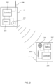
- FIG. 2 shows a representative one 2 of the transmitter units, and a mobile device 7.
- the transmitter unit 2 has an ultrasonic sounder 201, a controller 202 for causing the ultrasound transducer 201 to transmit ultrasonic signals, and battery 203 for supplying power to the transmitter unit. It also contains a radio antenna 208 and circuitry in the controller 202 for transmitting (and optionally receiving) Bluetooth Low Energy TM (BLE) radio signals.
- BLE Bluetooth Low Energy TM
- the other transmitter units 3, 4, 5 are similarly configured.
- the mobile device 7 has a microphone 204 capable of receiving ultrasonic signals from the transmitter units 2-5, a controller 205 for sampling and processing the received ultrasonic signals, a radio antenna 209 for transmitting and receiving BLE signals, and a battery 207 for powering the mobile device 7.
- the transmitter units 2-5 and mobile device 7 may have further standard electronic components such as further radio transceivers, wired-network interfaces, display screens, batteries, buttons, etc.
- the mobile device 7 is a tablet or mobile telephone (cellphone) such as an Apple TM or Android TM smart phone.
- ultrasound is not essential and other embodiments may instead transmit locating signals that are audible acoustic signals or that are electromagnetic signals such as infrared signals or radio signals.
- the controllers 202, 205 may include one or more processors, DSPs, ASICs and/or FPGAs. They may include memory for storing data and/or for storing software instructions to be executed by a processor or DSP. They may include any other appropriate analogue or digital components, including amplifiers, oscillators, filters, ADCs, DACs, RAM, flash memory, etc.
- transmitter units 2-5 are here shown as being static relative to the environment 1, it will be appreciated that, in other embodiments, they may be mobilee.g., one or more of the transmitter units could be a respective mobile telephone or device in the possession of a respective user.
- each transmitter unit 2-5 transmits, at intervals (e.g. every one second), an ultrasonic locating signal comprising a signature associated with that transmitter unit.
- the transmissions may be coordinated, e.g. by the server 9, to help reduce interference between nearby transmitter units.
- the transmission schedule for each transmitter unit 2-5 is published by the server 9, so that a processing system, such as the mobile device 7, can determine the times of transmissions of the ultrasonic signals by each transmitter unit 2-5. If each transmitter unit 2-5 transmits at regular intervals, then the schedule may comprise an offset value for each transmitter unit 2-5. This may be encoded as a time slot identifier.
- each transmitter unit 2-5 may transmit a 12ms long ultrasonic signal every 1,000ms, in an allocated one of 16 non-overlapping time slots, each of approximately 60ms duration.
- each unit can be allocated a unique time slot, but in larger rooms, or across a wider area, it will be necessary to allocate the same time slot to multiple transmitter units.
- time slots are shared only between transmitter units that are far apart, so the mobile unit 7 is unlikely to be in audible range of both at the same time.
- the ultrasonic signal from a transmitter unit 2-5 will decay so as to be practically undetectable by the mobile unit 7 after about 80ms from transmission (corresponding to a distance of 27 metres). Therefore, the time of arrival of a signal, relative to an expected transmission time slot, may be used to help identify the source transmitter unit for the signal, as described in more detail below.
- Each signature is encoded on an ultrasonic carrier-e.g., a 20 kHz or 40 kHz carrier.
- the signature may be encoded using any appropriate frequency-shift or phase-shift encoding, but in one set of embodiments, the signature of each transmitter unit 2-5 comprises a respective binary identifier encoded using frequency-shift-keying (FSK) modulation.
- FSK frequency-shift-keying
- the signature may be contained in a longer transmission that comprises one or more additional elements, such as a fixed preamble and/or a variable data portion, which may be encoded in the same ultrasonic carrier band as the signature.
- the low bandwidth of ultrasonic communication constrains the maximum bit-length that can be used in the signatures while still providing an acceptable update rate (e.g. once a second). Therefore, in a large deployment, the ultrasonic signatures may also be unique only within a locality, with the same signature being allocated to multiple transmitter units across the system. As with the time slots, ideally signatures are shared only between transmitter units that are far apart, so the mobile unit 7 is unlikely to be in audible range of both at the same time.
- the mobile device 7 receives and demodulates the ultrasound signals to identify signatures that have been transmitted by transmitter units 2-5 within audible range of the device 7. However, due to noise and interference, this decoding will not always be reliable.
- the mobile device 7 uses an internal clock to timestamp received signatures, representing a time of arrival for each signal.
- the mobile device 7 may be synchronised with each of the transmitter units 2-5 (and optionally with the server 9) and can therefore calculate at least one time of flight (ToF) value for each signature it receives by accessing scheduling data representative of a time of transmission of an acoustic signal by a respective acoustic transmitter unit and subtracting the time of arrival from the time of transmission.
- the scheduling data may be provided to the mobile device 7 by the server 9, e.g. over a radio communication link.
- the position of the mobile device 7 can be determined using geometric principles of trilateration (also referred to as multilateration).
- the clock synchronisation may be carried out using a radio channel, such as a Bluetooth Low Energy TM connection, or in any other suitable way.
- the mobile device 7 is not synchronised with the transmitters 2-5, and instead a time difference of flight (TDoF) method may be used to determine the position of the device 7. In this case, more transmitter units may have to be in range of the mobile device 7 for an accurate position estimate to be determined.
- ToF time difference of flight
- the position of the device 7 may be estimated in three dimensions (e.g., as an ⁇ x, y, z> Cartesian coordinates relative to a reference frame of the room 1 or building), or in two dimensions (e.g., ⁇ x, y> in a horizontal plane only), or in one dimension (e.g. as a distance, x, along a corridor).
- the position determination calculations may be performed on the mobile device 7, or the device 7 may send information about the received signals, such as timing and/or range data, to the server 9, which may perform part or all of the calculations described herein.
- the mobile device 7 will typically receive the same acoustic signal from a transmitter unit 2-5 along a direct path (assuming there is a clear line of sight) and also along one or more indirect paths, after reflection off one or more surfaces in the environment.
- the strength of the instances received along the indirect (reflected) signals will typically be lower than the strength of the direct-path signal, although this is not necessarily always the case (e.g., if a microphone on the device 7 is angled towards a highly reflective surface such as a glass window pane).
- the device 7 may use signal strength to help identify direct-path signals, for use in a position-determining algorithm.
- the times of flight of received direct-path signals can be input to a multilateration positioning algorithm.
- the times of flight of any reflections (echoes) are disregarded in the geometric fit process, although the reflected signals may in some embodiments be used to assist in decoding a received direct-path signature.
- the times of arrival of reflections may also be used when determining geometric information about the position of the device 7.
- Such embodiments may make use of known locations of major reflective surfaces in the environment. Techniques involving real and virtual transmitter locations, which may be employed in such embodiments, are disclosed in WO 2018/162885, filed 5 March 2018 .
- the location of the mobile device 7 may, in some embodiments, be estimated at least in part by estimating an impulse response function from multiple instances of one locating signal, received along a plurality of paths, each instance arriving at a different respective time. Doppler shift occurs whenever the mobile device 7 is moving towards or away from one or more of the transmitters units 2-5.
- the positioning system may therefore include a Doppler-shift compensation mechanism to enable accurate decoding of the transmitted signatures.
- It may be in the same building, on or the same site, as the room 1 or remote from ite.g. in a remote data centre accessed over the Internet.
- the mobile device 7 performs operations to mitigate this ambiguity before it inputs the timing or range information determined from a received signal to a positioning algorithm.
- This filtering may identify a single most probable source transmitter unit 2-5 for each received signal.
- the filtering may identify a strict subset of all the transmitter units in system and may pass data relating to this subset of the transmitter units to the positioning algorithm, to be used when calculating a positioning estimate for the mobile device 7.
- the filtering may take account of various factors, including:
- This earlier position estimate may be an earlier estimate determined from a set of ultrasonic signals received from the transmitter units 2-5, or it may be a position estimate determined by a different mechanism.
- each of the transmitter units 2-5 also transmits Bluetooth Low Energy TM (BLE) radio beacon signals at regular intervals.
- BLE Bluetooth Low Energy TM
- the mobile device 7 can use Bluetooth TM radio signals from the transmitter units 2-5 to determine an initial position estimate for the mobile device 7 using suitable processing, such as by measuring received signal strength indicators (RSSI), optionally also taking account of RF time-of-flight measurements.
- RSSI received signal strength indicators
- the BLE beacon transmitters could be physically separate from the transmitter units 2-5, or the initial position estimate could be determined using WiFi, NFC, UWB, GPS, cellular or infrared positioning, or any other location technology.
- the radio positioning system may be able to determine a location estimate with an accuracy of around 10-15 metres (at least in two horizontal dimensions), and a latency of no more than 10-15 seconds (corresponding to a typical human walking speed of around 1 m/s).
- these may be deployed at a density of approximately one beacon per 25 - 150m 2 . Given a typical distance between beacons of 5-12m, this can give a positioning accuracy of approximately 3-15m and a relatively low latency of under 10s.
- An important requirement for the radio positioning algorithm may not necessarily be high accuracy but rather delivering a robust conservative initial estimate of the position of the mobile device 7, which is well inside the area enclosed by the ultrasonic transmitter units 2-5.
- the mobile device 7 may transmit positioning signals-e.g. radio signals-to be received by static receiver units (which could be the same units 2-5).
- An initial position estimate could even be received from a human user, e.g. through a graphical user interface on the mobile device 7 that allows the user to identify his location on a map.
- a very first position estimate may be determined using, e.g. radio beacons, after which a time series of two or more position estimates may be determined using ultrasonic signals, with the spatial filtering for each subsequent ultrasonic-determined position estimate using the immediately preceding ultrasonic-determined position estimate.
- the device may continue obtaining updated BLE-based position estimates at intervals (e.g. once, twice or three times every five seconds), even while performing ultrasonic-based tracking in which the spatial filtering being based on the preceding ultrasound-based position estimate (e.g. with one new position estimate being calculated every one second).
- the BLE position estimates can be used to check the accuracy of each ultrasound-based position estimate, and a recent BLE position estimate will be available to re-initialise the spatial filtering if the position estimation becomes inaccurate.
- the filtering may be performed as a single step, or in multiple stages with each stage potentially reducing the number of transmitter units in a candidate set of source transmitter units for a particular received signal.
- the decoding of the signature may be performed after temporal and/or spatial filtering have been carried out, since this can efficiently reduce the time and/or energy required for the decoding process, which may be relatively resource intensive.
- FIG. 3 is a flow chart providing an overview of key operations carried out by the mobile device 7 when generating a time series of position estimates. In other embodiments, some or all of these operations may be performed on the server 9.
- the mobile device 7 is here assumed already to have been provided with transmission schedules for all the transmitter units in the system, including the transmitter units 2-5 in the room 1, and to have been synchronised with the transmitter units, e.g. by exchanging time-stamped with the server 9 via one or more radio relays (e.g. via BLE transceivers built into the transmitter units 2-5). It also has access to location coordinates for each transmitter unit in the system, in two or three dimensions.
- BLE beacon signals (e.g. transmitted by the transmitter units 2-5) are used to determine 300 an initial position estimate. This may have an accuracy only in the order of metres, whereas the system aims to track the mobile device 7 with an accuracy in the order of centimetres or better.
- a new BLE position estimate may be calculated whenever the mobile device 7 is first turned on, or if it ceases to receive any ultrasonic signals for a time, or if confidence in the series of position estimates falls below a minimum threshold.
- a relatively reliable (although not necessarily high-resolution) position estimate r_mobile is required at start-up of a positioning session, e.g. of a smartphone 7. For this reason, the duty cycling of the BLE receive may be disabled for the first 60 seconds of a session.
- a reliable initial position estimate r_mobile_BLE is typically determined from received BLE signals after a couple of seconds (i.e. after more than five to ten BLE beacons are received).
- the mobile device 7 processes each received BLE signal in the following way:
- the average_RSS_derived_range value may not actually be an accurate estimate of the true geometric range between the BLE beacon 2-5 and the mobile device 7; it is nevertheless still useful for crudely estimating the position of the mobile device 7 based on the RSS measurements.
- New BLE position estimates and spreads may be determined at regular or irregular intervals, e.g. every 1-5 seconds, even as the acoustic signals are processed.
- Incoming audio received at the microphone 204 is sampled and analysed to detect 301 an incoming ultrasonic locating signal from one of the transmitter units. This may involve a down-mixing process, using analogue and/or digital mixing techniques, to generate a stream of complex IQ baseband samples.
- the received signal may be critically sampled-i.e. at a sample rate close to the Nyquist frequency for the transmitted signatures.
- the received signature is detected by an appropriate technique; this could involve cross-correlation against template data, or using a deconvolution process, but in some embodiments it uses a sliding energy detector that simply detects burst of energy of 12ms duration around the carrier frequency (regardless of the encoded content).
- a temporal filtering step 303 is then performed to identify a first shortlist of candidate transmitter units for the received signal, based on the time of arrival and the known transmission schedules of all the transmitter units in the system.
- a more complex likelihood value may be calculated and used in this step, e.g. the P_time i value disclosed below, to which a threshold may be applied to filter out unlikely transmitter units, for example a threshold in the range 5 - 90%.
- a spatial filtering step 304 is then applied to the first shortlist of transmitter units, to obtain a reduced shortlist.
- This step makes use of the initial position estimate which, although not necessarily very accurate (because it was determined using an inherently less accurate positioning method such as BLE beacons, or because some time has elapsed since it was calculated during which the mobile device 7 may have moved), can nevertheless provide sufficient information to usefully restrict the pool of likely transmitter units that may be the origin of the positioning signal received by the mobile device 7.
- the controller 205 considers each transmitter unit, i , on the first shortlist in turn. For each candidate transmitter unit, it subtracts the time of the most recent transmission by that transmitter unit from the time of arrival to determine a time of flight. (Earlier transmissions by the same unit will have long since decayed, assuming transmissions are made on a one-second cycle.) From this, a time-of-flight range value, R_tof i , can be calculated by multiplying by the speed of sound through air. A thermometer may be used to adjust a default speed value based on the ambient temperature.
- This var_eff value may be calculated in any appropriate way. It may simply be a fixed constant value (e.g. 4 m 2 ) or it may depend on one or more factors, such as any of:
- the standard deviation varies between 0 and 10 metres (e.g. typically being between 1m and 10m), so var_eff may vary between 0 and 100 m 2 .
- the variance parameter var_eff is set equal to 4 m 2 if r_mobile is an ultrasound-derived position estimate, r_mobile_US, that is less than three seconds old, and if r_mobile lies within an error ellipse around r_mobile_BLE defined by three times r_mobile_BLE_spread in each dimension; and is set equal to the lower or 49 m 2 and 0.7 x (r_mobile_US - r_mobile_BLE) 2 in other cases.
- P_spatial is a Gaussian function.
- the exponent and/or exponential term may optionally be further scaled to define P_spatial as a normal distribution, to be a true probability density function; however, this may not be necessary in some embodiments since the P_spatial likelihood values for the transmitter units can still indicate relative likelihood even if they do not sum up to one.
- P_spatial i for each transmitter unit i in the first shortlist is then compared against a threshold value and those transmitter units that have a P_spatial value below the threshold are filtered out, leaving a potentially reduced shortlist of candidate transmitter units.
- a more complex selection criterion may be used, e.g. to additionally filter out at least a minimum percentage of the transmitter units having the lowest P_spatial values.
- the temporal filing 303 and spatial filtering 304 may involve a combined filtering step, optionally in addition to individual filtering, or instead.
- This combined filtering may comprise calculating a temporal likelihood value, P_time i , representing a likelihood of each transmitter unit i in the system being the source transmitter unit, based on the time of arrival and the most recent scheduled transmission from that transmitter unit, and by then applying a minimum threshold to the product P_time i x P_spatial i to identify a shortlist of candidate transmitter units.
- the value P_time i may be calculated using a rectangular window of 60ms duration, with additional symmetric Gaussian tails on both ends; the start of the rectangle may be positioned at the schedule transmission start time for the transmitter unit i , with the value P_time i being equal to the value of the windowing function at the time of arrival.
- P_time i is at a maximum if the signal is received within 60ms of its scheduled transmission, and is lower if the signal is received early (possible if there is a clock synchronisation error), or later than this.
- a value other than 60ms may be used, or the P_time function may be defined in any other appropriate way. It may be scaled to be a probability density function (i.e. integrating to one) although this may not be necessary.
- the temporal and spatial filtering may be configured always to identify a single most likely transmitter unit, or they may be configured to output a set of likely transmitter units which may contain more than one transmitter unit.
- the controller 205 in the mobile device 7 then passes data for the reduced shortlist of candidate transmitter units to a decoder algorithm to applying decoding filtering 305 to identify a source transmitter unit (or potentially more than one likely transmitter units).
- the decoder may perform a cross-correlation operation on the received signal samples, correlating against stored template data representative of the signature of a transmitter unit in the reduced shortlist. It may do this for each transmitter unit in the reduced shortlist. This is a relatively processing intensive step, so the earlier temporal filtering 303 and spatial filtering 304 serve to reduce the time and power of the decoding step 305.
- a respective correlation coefficient may be determined for each transmitter unit in the reduced shortlist, which is a decoding likelihood value representing a likelihood of the respective transmitter unit being the source of the received signal, based on the decoding confidence.
- the decoding filtering may always select the one transmitter unit having the highest decoding likelihood value to be the identified source transmitter unit, optionally so long as the likelihood value is above a minimum threshold value, or it may potentially select a set of one or more transmitter units having a decoding likelihood above a threshold.
- some embodiments might combine the temporal, spatial and decoding filtering into a single step (e.g. by multiplying the likelihood values generated by all three steps together, for each transmitter unit in the system), applying the temporal and spatial filtering before starting the decoding step 305 can provide computational benefits.
- a minimum likelihood threshold is applied at any of the temporal, spatial and decoding filtering steps 303-305, that none of the transmitter units meets, the decoding of that signal may be aborted, with the process cycling round to detect the next incoming signal 301.
- a time-of-flight range value for the signal is added 306 to a buffer of range values, along with the identity or coordinates of the transmitter unit. If more than one transmitter unit passes the filtering, multiple range values may be added 306 to the buffer, assuming each transmitter unit is the source.
- An associated confidence level may be stored with each range value-e.g. being the product of the temporal, spatial and decoding likelihood values.
- a time stamp may also be stored-e.g. the time of arrival of the signal.
- the decoder may be configured to determine a more accurate time of arrival than the energy detector in step 302, e.g. based on a peak location in a cross-correlation operation, which may be used to calculate an updated ToF range value to use in the subsequent positioning algorithm.
- a new position estimation for the mobile device 7 is then calculated 307 by solving a geometric minimisation problem (so long as the buffer contains a minimum number of range values-e.g. containing values for at least three different transmitter units 2-5).
- each buffered range value may be used to weight values differently in the positioning algorithm-e.g. to give more weight to newer and/or more confident range values.
- Old range data may be discarded from the buffer, or be given a lower weighting based on its age.
- the algorithm may use likelihood information to weight the range data according to a confidence in the accuracy of the assignment of the range to a particular transmitter unit.
- the position estimation algorithm solves a linear optimisation problem (e.g. a weighted least-squares regression), relating to the intersection of spheres (or of hyperboloids if using TDOA positioning).
- the position estimation algorithm solves the optimisation problem to determine a new position estimate. It does this by finding a position that minimises a cost function (i.e. an objective function).
- Each transmitter unit i is given a weighting, w i .
- the weight, w i may include an absolute component, e.g. which depends on the variance of the measurements for a single transmitter unit i. It may also include a relative component, rel_w i , which may represent a confidence in the range value for the transmitter unit i relative to the other transmitter units. This confidence may be based on the filtering likelihoods and the age of the most recent range value in the buffer for that transmitter unit.
- the cost function is normalised for the relative weights, rel_w i , but not for the absolute weight components. This is because the absolute component (e.g.
- the new position estimate is then processed 308 as desired. It may be used to control a function on the mobile device 7. It may be communicated to the server 9, e.g. over a BLE link.
- the new position estimate may be combined with data from an inertial measurement unit (IMU) or other sensors, such as velocity data or other position estimates. It may be smoothed using previously determined position estimates. It may be input to a Kalman filter module to generate improved position data. This Kalman filter module may combine acoustic-based position estimates with data from other sensors, such as accelerometers, to improve accuracy even further.
- IMU inertial measurement unit
- Kalman filter module may combine acoustic-based position estimates with data from other sensors, such as accelerometers, to improve accuracy even further.
- the new position estimate (optionally after such post-processing) may be displayed 304 on a map, which could be shown on a screen of the device 7 or of a remote device-e.g. of a client computer connected to the server 9.
- this display step is not always required, and the position estimate may be used in other ways instead-e.g. simply being stored in memory for future potential use, or being processed to check if a preconfigured geo-fence has been crossed, or to give audible navigation cues to the user 6, or to display location-dependent advertising on the mobile device 7.
- the controller 205 may be configured only to seed each spatial filter with the latest ultrasound-based position estimate if the latest ultrasound-based position estimate, r_mobile_US, is consistent with a recently-obtained BLE-based position estimate, r_mobile_BLE-e.g.
- the mobile device 7 can continue to generate new BLE-based position estimates at intervals, in parallel with tracking the position of the mobile device 7 primarily using received ultrasound signals. If the ultrasound-derived position estimate lies too far away from the BLE-based estimate, the positioning process may set r_mobile equal to the latest BLE-based estimate in the next cycle.
Landscapes
- Physics & Mathematics (AREA)
- Engineering & Computer Science (AREA)
- General Physics & Mathematics (AREA)
- Radar, Positioning & Navigation (AREA)
- Remote Sensing (AREA)
- Measurement Of Velocity Or Position Using Acoustic Or Ultrasonic Waves (AREA)
- Stereophonic System (AREA)
Claims (15)
- Verfahren zum Bestimmen einer Positionsschätzung für eine mobile Vorrichtung (7), wobei das Verfahren Folgendes umfasst:Empfangen einer ersten Positionsschätzung für eine mobile Vorrichtung (7); undEmpfangen eines akustischen Signals an der mobilen Vorrichtung (7), wobei das akustische Signal von einer einer Vielzahl von akustischen Sendeeinheiten (2, 3, 4, 5) mit bekanntem Standort gesendet wird, die jeweils in Abständen jeweilige akustische Signale senden; dadurch gekennzeichnet, dass das Verfahren weiter umfasst:für jede der Vielzahl von akustischen Sendeeinheiten (2, 3, 4, 5), Bestimmen von räumlichen Wahrscheinlichkeitsdaten, die eine Wahrscheinlichkeit darstellen, dass das empfangene akustische Signal von der jeweiligen akustischen Sendeeinheit (2, 3, 4, 5) gesendet wurde, durch Vergleichen von i) einem Flugzeitbereichswert, der aus einer Ankunftszeit des empfangenen akustischen Signals an der mobilen Vorrichtung (7) bestimmt wird, und Planungsdaten, die eine Sendezeit eines akustischen Signals durch die jeweilige akustische Sendeeinheit (2, 3, 4, 5) darstellen, mit ii) einem geometrischen Entfernungswert, der eine Entfernung zwischen der jeweiligen akustischen Sendeeinheit (2, 3, 4, 5) und der ersten Positionsschätzung darstellt;Verwenden der räumlichen Wahrscheinlichkeitsdaten zum Identifizieren einer echten Teilmenge einer oder mehrerer der Vielzahl von akustischen Sendeeinheiten (2, 3, 4, 5); undVerwenden von Informationen bezüglich der Positionen der akustischen Sendeeinheiten (2, 3, 4, 5) in der identifizierten Teilmenge und/oder bezüglich der von den akustischen Sendeeinheiten (2, 3, 4, 5) in der identifizierten Teilmenge gesendeten akustischen Signalen beim Bestimmen einer zweiten Positionsschätzung für die mobile Vorrichtung (7).
- Verfahren nach Anspruch 1, wobei, nachdem die Teilmenge identifiziert wurde, die zweite Positionsschätzung bestimmt wird, ohne Informationen bezüglich der Position einer der akustischen Sendeeinheiten (2, 3, 4, 5) zu verwenden, die sich nicht in der identifizierten Teilmenge befindet, und ohne Informationen bezüglich der von einer der akustischen Sendeeinheiten (2, 3, 4, 5) gesendeten akustischen Signale zu verwenden, die sich nicht in der identifizierten Teilmenge befindet.
- Verfahren nach Anspruch 1 oder Anspruch 2, das Bestimmen der räumlichen Wahrscheinlichkeitsdaten für jede akustische Sendeeinheit (2, 3, 4, 5) durch Vergleichen des jeweiligen Flugzeitbereichswerts mit einer jeweiligen statistischen Verteilung umfasst, die Wahrscheinlichkeit gegenüber Bereich darstellt, die einen Erwartungswert aufweist, der dem geometrischen Entfernungswert für die jeweilige akustische Sendeeinheit (2, 3, 4, 5) entspricht.
- Verfahren nach einem vorstehenden Anspruch, wobei die erste Positionsschätzung zumindest teilweise unter Verwendung eines oder mehrerer elektromagnetischer oder magnetischer Signale bestimmt wird, die von der mobilen Vorrichtung (7) empfangen oder gesendet werden.
- Positionierungssystem, umfassend ein Verarbeitungssystem (7, 9), das konfiguriert ist zum:Empfangen einer ersten Positionsschätzung für eine mobile Vorrichtung (7);Empfangen von Daten, die ein von der mobilen Vorrichtung (7) empfangenes akustisches Signal darstellen, von einer einer Vielzahl von akustischen Sendeeinheiten (2, 3, 4, 5) mit bekanntem Standort, die dazu konfiguriert sind, in regelmäßigen Abständen jeweilige akustische Signale zu senden;dadurch gekennzeichnet, dass das Verarbeitungssystem konfiguriert ist zum:Bestimmen, für jede der Vielzahl von akustischen Sendeeinheiten (2, 3, 4, 5), von räumlichen Wahrscheinlichkeitsdaten, die eine Wahrscheinlichkeit darstellen, dass das empfangene akustische Signal von der jeweiligen akustischen Sendeeinheit (2, 3, 4, 5) gesendet wurde, durch Vergleichen von i) einem Flugzeitbereichswert, der aus einer Ankunftszeit des empfangenen akustischen Signals an der mobilen Vorrichtung (7) bestimmt wird, und Planungsdaten, die eine Sendezeit eines akustischen Signals durch die jeweilige akustische Sendeeinheit (2, 3, 4, 5) darstellen, mit ii) einem geometrischen Entfernungswert, der eine Entfernung zwischen der jeweiligen akustischen Sendeeinheit (2, 3, 4, 5) und der ersten Positionsschätzung darstellt;Verarbeiten der räumlichen Wahrscheinlichkeitsdaten, um eine echte Teilmenge einer oder mehrerer der Vielzahl von akustischen Sendeeinheiten (2, 3, 4, 5) zu identifizieren; undVerarbeiten von Informationen bezüglich der Positionen der akustischen Sendeeinheiten (2, 3, 4, 5) in der identifizierten Teilmenge und/oder bezüglich der von den akustischen Sendeeinheiten (2, 3, 4, 5) in der identifizierten Teilmenge gesendeten akustischen Signalen, um eine zweite Positionsschätzung für die mobile Vorrichtung (7) zu bestimmen.
- Positionierungssystem nach Anspruch 5, wobei das Verarbeitungssystem (7, 9) dazu konfiguriert ist, die echte Teilmenge so zu identifizieren, dass jede akustische Sendeeinheit (2, 3, 4, 5) in der identifizierten Teilmenge eine höhere Wahrscheinlichkeit dafür aufweist, das von der mobilen Vorrichtung (7) empfangene akustische Signal gesendet zu haben, als zumindest eine akustische Sendeeinheit (2, 3, 4, 5) der Vielzahl von akustischen Sendeeinheiten (2, 3, 4, 5), die sich nicht in der identifizierten Teilmenge befindet.
- Positionierungssystem nach Anspruch 5 oder Anspruch 6, wobei das Verarbeitungssystem (7, 9) dazu konfiguriert ist, nach Identifizieren der Teilmenge einer oder mehrerer akustischer Sendeeinheiten (2, 3, 4, 5) die zweite Positionsschätzung zu bestimmen, ohne Informationen bezüglich der Position einer der akustischen Sendeeinheiten (2, 3, 4, 5) zu verwenden, die sich nicht in der identifizierten Teilmenge befindet, und ohne Informationen bezüglich der von einer der akustischen Sendeeinheiten (2, 3, 4, 5) gesendeten akustischen Signale zu verwenden, die sich nicht in der identifizierten Teilmenge befindet.
- Positionierungssystem nach einem der Ansprüche 5 bis 7, wobei das Verarbeitungssystem (7, 9) dazu konfiguriert ist, die räumlichen Wahrscheinlichkeitsdaten für jede akustische Sendeeinheit (2, 3, 4, 5) durch Vergleichen des jeweiligen Flugzeitbereichswerts mit einer jeweiligen statistischen Verteilung zu bestimmen, die Wahrscheinlichkeit gegenüber Bereich darstellt, die einen Erwartungswert aufweist, der gleich dem geometrischen Entfernungswert für die jeweilige akustische Sendeeinheit (2, 3, 4, 5) ist.
- Positionierungssystem nach einem der Ansprüche 5 bis 8, wobei das Verarbeitungssystem (7, 9) dazu konfiguriert ist, zeitliche Wahrscheinlichkeitsdaten für jede einer zweiten Vielzahl der akustischen Sendeeinheiten (2, 3, 4, 5) zu bestimmen, die dazu konfiguriert sind, jeweilige akustische Signale in Abständen zu senden, wobei die zeitlichen Wahrscheinlichkeitsdaten von i) einer Ankunftszeit des empfangenen akustischen Signals an der mobilen Vorrichtung (7) und ii) Planungsdaten, die eine Sendezeit eines akustischen Signals durch die jeweilige akustische Sendeeinheit (2, 3, 4, 5) darstellen, abhängen, jedoch nicht von einer Positionsschätzung für die mobile Vorrichtung (7) abhängen, und wobei die zeitlichen Wahrscheinlichkeitsdaten eine Wahrscheinlichkeit darstellen, dass das empfangene akustische Signal von einer jeweiligen akustischen Sendeeinheit (2, 3, 4, 5) gesendet wurde.
- Positionierungssystem nach einem der Ansprüche 5 bis 9, wobei die von der Vielzahl von akustischen Sendeeinheiten (2, 3, 4, 5) gesendeten akustischen Signale jeweilige Identifikationsdaten für die jeweilige akustische Sendeeinheit (2, 3, 4, 5) kodieren, und wobei das Verarbeitungssystem (7, 9) dazu konfiguriert ist, das empfangene akustische Signal unter Verwendung jeweiliger Identifikationsdaten zu dekodieren, die mit jeder der akustischen Sendeeinheiten (2, 3, 4, 5) in der identifizierten Teilmenge verknüpft sind.
- Positionierungssystem nach einem der Ansprüche 5 bis 10, wobei das Verarbeitungssystem (7, 9) dazu konfiguriert ist, die zweite Positionsschätzung durch Lösen eines geometrischen Optimierungsproblems zu bestimmen, das die Positionen einer oder mehrerer der Vielzahl von akustischen Sendeeinheiten (2, 3, 4, 5) beinhaltet.
- Positionierungssystem nach einem der Ansprüche 5 bis 11, das eine elektromagnetische oder magnetische Sender- oder Empfängereinheit umfasst, die zum Senden oder Empfangen elektromagnetischer oder magnetischer Signale konfiguriert ist, wobei die mobile Vorrichtung (7) zum Empfangen oder Senden der elektromagnetischen oder magnetischen Signale konfiguriert ist, und wobei das Verarbeitungssystem (7, 9) zum Bestimmen der ersten Positionsschätzung zumindest teilweise unter Verwendung eines oder mehrerer elektromagnetischer oder magnetischer Signale konfiguriert ist, die zwischen der elektromagnetischen oder magnetischen Sender- oder Empfängereinheit und der mobilen Vorrichtung (7) gesendet werden.
- Positionierungssystem nach einem der Ansprüche 5 bis 12, wobei das Verarbeitungssystem (7, 9) dazu konfiguriert ist, eine Abfolge von zwei oder mehr Positionsschätzungen im Zeitverlauf zu bestimmen, indem es von der mobilen Vorrichtung (7) empfangene akustische Signale verarbeitet, und dazu konfiguriert ist, räumliche Wahrscheinlichkeitsdaten zu bestimmen, wenn jede aufeinanderfolgende Positionsschätzung bestimmt wird, indem ein jeweiliger Flugzeitbereichswert mit einem jeweiligen geometrischen Entfernungswert verglichen wird, der eine Entfernung zwischen einer jeweiligen akustischen Sendeeinheit (2, 3, 4, 5) und einer unmittelbar vorhergehenden Positionsschätzung in der Abfolge von zwei oder mehr Positionsschätzungen darstellt.
- Positionierungssystem nach einem der Ansprüche 5 bis 13, umfassend die mobile Einheit oder eine oder mehrere der Vielzahl von akustischen Sendeeinheiten (2, 3, 4, 5), wobei die akustischen Signale Ultraschallsignale sind.
- Computerprogramm, das Anweisungen umfasst, die, wenn sie von einem Verarbeitungssystem (7, 9) ausgeführt werden, das Verarbeitungssystem (7, 9) zu Folgendem veranlassen:Empfangen einer ersten Positionsschätzung für eine mobile Vorrichtung (7); undEmpfangen von Daten, die ein akustisches Signal darstellen, das von der mobilen Vorrichtung (7) von einer einer Vielzahl von akustischen Sendeeinheiten (2, 3, 4, 5) mit bekanntem Standort empfangen wird, die dazu konfiguriert sind, in regelmäßigen Abständen jeweilige akustische Signale zu senden; dadurch gekennzeichnet, dass die Anweisungen, wenn sie vom Verarbeitungssystem (7, 9) ausgeführt werden, das Verarbeitungssystem zu Folgendem veranlassen:Bestimmen, für jede der Vielzahl von akustischen Sendeeinheiten (2, 3, 4, 5), von räumlichen Wahrscheinlichkeitsdaten, die eine Wahrscheinlichkeit darstellen, dass das empfangene akustische Signal von der jeweiligen akustischen Sendeeinheit (2, 3, 4, 5) gesendet wurde, durch Vergleichen von i) einem Flugzeitbereichswert, der aus einer Ankunftszeit des empfangenen akustischen Signals an der mobilen Vorrichtung (7) bestimmt wird, und Planungsdaten, die eine Sendezeit eines akustischen Signals durch die jeweilige akustische Sendeeinheit (2, 3, 4, 5) darstellen, mit ii) einem geometrischen Entfernungswert, der eine Entfernung zwischen der jeweiligen akustischen Sendeeinheit (2, 3, 4, 5) und der ersten Positionsschätzung darstellt;Verarbeiten der räumlichen Wahrscheinlichkeitsdaten, um eine echte Teilmenge einer oder mehrerer der Vielzahl von akustischen Sendeeinheiten (2, 3, 4, 5) zu identifizieren; undVerarbeiten von Informationen bezüglich der Positionen der akustischen Sendeeinheiten (2, 3, 4, 5) in der identifizierten Teilmenge und/oder bezüglich der von den akustischen Sendeeinheiten (2, 3, 4, 5) in der identifizierten Teilmenge gesendeten akustischen Signalen, um eine zweite Positionsschätzung für die mobile Vorrichtung (7) zu bestimmen.
Applications Claiming Priority (2)
| Application Number | Priority Date | Filing Date | Title |
|---|---|---|---|
| GBGB2000799.3A GB202000799D0 (en) | 2020-01-20 | 2020-01-20 | Likelihood-based acoustic positing |
| PCT/EP2021/051213 WO2021148473A1 (en) | 2020-01-20 | 2021-01-20 | Likelihood-based acoustic positioning |
Publications (3)
| Publication Number | Publication Date |
|---|---|
| EP4094086A1 EP4094086A1 (de) | 2022-11-30 |
| EP4094086B1 true EP4094086B1 (de) | 2025-03-05 |
| EP4094086C0 EP4094086C0 (de) | 2025-03-05 |
Family
ID=69636901
Family Applications (1)
| Application Number | Title | Priority Date | Filing Date |
|---|---|---|---|
| EP21701304.4A Active EP4094086B1 (de) | 2020-01-20 | 2021-01-20 | Auf wahrscheinlichkeit basierende akustische positionierung |
Country Status (9)
| Country | Link |
|---|---|
| US (1) | US12196876B2 (de) |
| EP (1) | EP4094086B1 (de) |
| JP (1) | JP2023510957A (de) |
| KR (1) | KR20220124259A (de) |
| CN (1) | CN115362386A (de) |
| AU (1) | AU2021209822B2 (de) |
| CA (1) | CA3165154A1 (de) |
| GB (1) | GB202000799D0 (de) |
| WO (1) | WO2021148473A1 (de) |
Families Citing this family (3)
| Publication number | Priority date | Publication date | Assignee | Title |
|---|---|---|---|---|
| CN111948606B (zh) * | 2020-08-12 | 2023-04-07 | 中国计量大学 | 一种基于uwb/蓝牙同步的声音定位系统及定位方法 |
| US12445801B2 (en) * | 2022-09-30 | 2025-10-14 | Zebra Technologies Corporation | Expansion of geo-fence size based on a tag's likely location |
| US20250251485A1 (en) * | 2023-03-14 | 2025-08-07 | Apple Inc. | Pressure Sensor for Three-Dimensional Localization |
Family Cites Families (13)
| Publication number | Priority date | Publication date | Assignee | Title |
|---|---|---|---|---|
| CA2570029A1 (en) * | 2004-06-09 | 2005-12-22 | International Business Machines Corporation | Distance measurement system, distance measurement method, information processing apparatus, program and recording medium |
| JP4997637B2 (ja) * | 2007-08-20 | 2012-08-08 | 学校法人慶應義塾 | 位置推定システム及びプログラム |
| JP5396305B2 (ja) * | 2010-02-23 | 2014-01-22 | 日本電信電話株式会社 | 位置算出装置、方法及びプログラム |
| JP2011214920A (ja) * | 2010-03-31 | 2011-10-27 | Oki Electric Industry Co Ltd | 位置推定装置、位置推定方法及びプログラム |
| US9689958B1 (en) * | 2013-03-20 | 2017-06-27 | Ben Wild | Device positioning using acoustic and radio signals |
| CN103728642B (zh) * | 2013-12-30 | 2016-03-23 | 深圳先进技术研究院 | 定位方法和系统 |
| JP2016128765A (ja) * | 2015-01-09 | 2016-07-14 | 富士通株式会社 | 位置情報特定システム |
| JP6716892B2 (ja) * | 2015-02-25 | 2020-07-01 | 株式会社リコー | 位置情報発信システム、及び位置情報発信装置 |
| JP2016223981A (ja) * | 2015-06-02 | 2016-12-28 | 株式会社東芝 | 測位対象端末、測位ノード、及び測位システム |
| GB201703647D0 (en) | 2017-03-07 | 2017-04-19 | Sonitor Technologies As | Ultrasound position-determination system |
| JP6739389B2 (ja) * | 2017-03-30 | 2020-08-12 | 東芝プラントシステム株式会社 | 位置特定装置および位置特定方法 |
| GB201713639D0 (en) | 2017-08-24 | 2017-10-11 | Sonitor Technologies As | Position determining system |
| US11567195B2 (en) * | 2018-01-29 | 2023-01-31 | Sonitor Technologies As | Ad hoc positioning of mobile devices using near ultrasound signals |
-
2020
- 2020-01-20 GB GBGB2000799.3A patent/GB202000799D0/en not_active Ceased
-
2021
- 2021-01-20 EP EP21701304.4A patent/EP4094086B1/de active Active
- 2021-01-20 CA CA3165154A patent/CA3165154A1/en active Pending
- 2021-01-20 KR KR1020227027952A patent/KR20220124259A/ko active Pending
- 2021-01-20 US US17/793,438 patent/US12196876B2/en active Active
- 2021-01-20 CN CN202180009927.XA patent/CN115362386A/zh active Pending
- 2021-01-20 AU AU2021209822A patent/AU2021209822B2/en active Active
- 2021-01-20 JP JP2022544059A patent/JP2023510957A/ja active Pending
- 2021-01-20 WO PCT/EP2021/051213 patent/WO2021148473A1/en not_active Ceased
Also Published As
| Publication number | Publication date |
|---|---|
| CN115362386A (zh) | 2022-11-18 |
| AU2021209822B2 (en) | 2025-12-18 |
| EP4094086A1 (de) | 2022-11-30 |
| US12196876B2 (en) | 2025-01-14 |
| CA3165154A1 (en) | 2021-07-29 |
| GB202000799D0 (en) | 2020-03-04 |
| WO2021148473A1 (en) | 2021-07-29 |
| KR20220124259A (ko) | 2022-09-13 |
| EP4094086C0 (de) | 2025-03-05 |
| JP2023510957A (ja) | 2023-03-15 |
| US20230039932A1 (en) | 2023-02-09 |
| AU2021209822A1 (en) | 2022-08-18 |
Similar Documents
| Publication | Publication Date | Title |
|---|---|---|
| US7764574B2 (en) | Positioning system using ultrasonic waves and method for operating the same | |
| US8203910B2 (en) | Autonomous ultrasonic indoor location system, apparatus and method | |
| EP4094086B1 (de) | Auf wahrscheinlichkeit basierende akustische positionierung | |
| US20170223510A1 (en) | Generating a model for positioning | |
| EP4022337B1 (de) | Positionsbestimmung | |
| EP2952925A1 (de) | Verfahren, Vorrichtung und System zur Innenraumlokalisierung und -verfolgung mittels Ultrabreitbandfunksignalen | |
| WO2020163661A1 (en) | Methods, systems, and computer readable media for time-slotted ultra-wide-band object tracking | |
| Aguilera et al. | Broadband acoustic local positioning system for mobile devices with multiple access interference cancellation | |
| CN112378407A (zh) | 基于智能手机传感器与声波定位相结合的室内定位方法 | |
| WO2013171679A1 (en) | Handheld-device-based indoor localization system and method | |
| US12117551B2 (en) | Frequency-shift determination | |
| WO2018184096A1 (en) | System and method of generating observations for radio beacon travel path determination | |
| KR100752580B1 (ko) | 위치 추정 방법 | |
| CN109061562A (zh) | 基于定位芯片内部参数的对象定位方法、装置和电子设备 | |
| EP3193191B1 (de) | Verfahren und system zur messung von standort und/oder ausrichtung | |
| Quyum | Guidelines for Indoor Positioning |
Legal Events
| Date | Code | Title | Description |
|---|---|---|---|
| STAA | Information on the status of an ep patent application or granted ep patent |
Free format text: STATUS: UNKNOWN |
|
| STAA | Information on the status of an ep patent application or granted ep patent |
Free format text: STATUS: THE INTERNATIONAL PUBLICATION HAS BEEN MADE |
|
| PUAI | Public reference made under article 153(3) epc to a published international application that has entered the european phase |
Free format text: ORIGINAL CODE: 0009012 |
|
| STAA | Information on the status of an ep patent application or granted ep patent |
Free format text: STATUS: REQUEST FOR EXAMINATION WAS MADE |
|
| 17P | Request for examination filed |
Effective date: 20220815 |
|
| AK | Designated contracting states |
Kind code of ref document: A1 Designated state(s): AL AT BE BG CH CY CZ DE DK EE ES FI FR GB GR HR HU IE IS IT LI LT LU LV MC MK MT NL NO PL PT RO RS SE SI SK SM TR |
|
| DAV | Request for validation of the european patent (deleted) | ||
| DAX | Request for extension of the european patent (deleted) | ||
| RAP1 | Party data changed (applicant data changed or rights of an application transferred) |
Owner name: SONITOR TECHNOLOGIES AS |
|
| GRAP | Despatch of communication of intention to grant a patent |
Free format text: ORIGINAL CODE: EPIDOSNIGR1 |
|
| STAA | Information on the status of an ep patent application or granted ep patent |
Free format text: STATUS: GRANT OF PATENT IS INTENDED |
|
| INTG | Intention to grant announced |
Effective date: 20240820 |
|
| GRAS | Grant fee paid |
Free format text: ORIGINAL CODE: EPIDOSNIGR3 |
|
| GRAA | (expected) grant |
Free format text: ORIGINAL CODE: 0009210 |
|
| STAA | Information on the status of an ep patent application or granted ep patent |
Free format text: STATUS: THE PATENT HAS BEEN GRANTED |
|
| AK | Designated contracting states |
Kind code of ref document: B1 Designated state(s): AL AT BE BG CH CY CZ DE DK EE ES FI FR GB GR HR HU IE IS IT LI LT LU LV MC MK MT NL NO PL PT RO RS SE SI SK SM TR |
|
| REG | Reference to a national code |
Ref country code: GB Ref legal event code: FG4D |
|
| REG | Reference to a national code |
Ref country code: CH Ref legal event code: EP |
|
| REG | Reference to a national code |
Ref country code: IE Ref legal event code: FG4D |
|
| REG | Reference to a national code |
Ref country code: DE Ref legal event code: R096 Ref document number: 602021027111 Country of ref document: DE |
|
| U01 | Request for unitary effect filed |
Effective date: 20250327 |
|
| U07 | Unitary effect registered |
Designated state(s): AT BE BG DE DK EE FI FR IT LT LU LV MT NL PT RO SE SI Effective date: 20250403 |
|
| PG25 | Lapsed in a contracting state [announced via postgrant information from national office to epo] |
Ref country code: RS Free format text: LAPSE BECAUSE OF FAILURE TO SUBMIT A TRANSLATION OF THE DESCRIPTION OR TO PAY THE FEE WITHIN THE PRESCRIBED TIME-LIMIT Effective date: 20250605 |
|
| PG25 | Lapsed in a contracting state [announced via postgrant information from national office to epo] |
Ref country code: ES Free format text: LAPSE BECAUSE OF FAILURE TO SUBMIT A TRANSLATION OF THE DESCRIPTION OR TO PAY THE FEE WITHIN THE PRESCRIBED TIME-LIMIT Effective date: 20250305 |
|
| PG25 | Lapsed in a contracting state [announced via postgrant information from national office to epo] |
Ref country code: HR Free format text: LAPSE BECAUSE OF FAILURE TO SUBMIT A TRANSLATION OF THE DESCRIPTION OR TO PAY THE FEE WITHIN THE PRESCRIBED TIME-LIMIT Effective date: 20250305 |
|
| PG25 | Lapsed in a contracting state [announced via postgrant information from national office to epo] |
Ref country code: GR Free format text: LAPSE BECAUSE OF FAILURE TO SUBMIT A TRANSLATION OF THE DESCRIPTION OR TO PAY THE FEE WITHIN THE PRESCRIBED TIME-LIMIT Effective date: 20250606 |
|
| PG25 | Lapsed in a contracting state [announced via postgrant information from national office to epo] |
Ref country code: SM Free format text: LAPSE BECAUSE OF FAILURE TO SUBMIT A TRANSLATION OF THE DESCRIPTION OR TO PAY THE FEE WITHIN THE PRESCRIBED TIME-LIMIT Effective date: 20250305 |
|
| PG25 | Lapsed in a contracting state [announced via postgrant information from national office to epo] |
Ref country code: PL Free format text: LAPSE BECAUSE OF FAILURE TO SUBMIT A TRANSLATION OF THE DESCRIPTION OR TO PAY THE FEE WITHIN THE PRESCRIBED TIME-LIMIT Effective date: 20250305 |
|
| PG25 | Lapsed in a contracting state [announced via postgrant information from national office to epo] |
Ref country code: CZ Free format text: LAPSE BECAUSE OF FAILURE TO SUBMIT A TRANSLATION OF THE DESCRIPTION OR TO PAY THE FEE WITHIN THE PRESCRIBED TIME-LIMIT Effective date: 20250305 |
|
| PG25 | Lapsed in a contracting state [announced via postgrant information from national office to epo] |
Ref country code: SK Free format text: LAPSE BECAUSE OF FAILURE TO SUBMIT A TRANSLATION OF THE DESCRIPTION OR TO PAY THE FEE WITHIN THE PRESCRIBED TIME-LIMIT Effective date: 20250305 |
|
| PG25 | Lapsed in a contracting state [announced via postgrant information from national office to epo] |
Ref country code: IS Free format text: LAPSE BECAUSE OF FAILURE TO SUBMIT A TRANSLATION OF THE DESCRIPTION OR TO PAY THE FEE WITHIN THE PRESCRIBED TIME-LIMIT Effective date: 20250705 |
|
| PLBE | No opposition filed within time limit |
Free format text: ORIGINAL CODE: 0009261 |
|
| STAA | Information on the status of an ep patent application or granted ep patent |
Free format text: STATUS: NO OPPOSITION FILED WITHIN TIME LIMIT |
|
| REG | Reference to a national code |
Ref country code: CH Ref legal event code: L10 Free format text: ST27 STATUS EVENT CODE: U-0-0-L10-L00 (AS PROVIDED BY THE NATIONAL OFFICE) Effective date: 20260114 |
|
| 26N | No opposition filed |
Effective date: 20251208 |
|
| U20 | Renewal fee for the european patent with unitary effect paid |
Year of fee payment: 6 Effective date: 20260127 |
|
| PGFP | Annual fee paid to national office [announced via postgrant information from national office to epo] |
Ref country code: GB Payment date: 20260120 Year of fee payment: 6 |
|
| PGFP | Annual fee paid to national office [announced via postgrant information from national office to epo] |
Ref country code: NO Payment date: 20260126 Year of fee payment: 6 |