EP4094040B1 - Three-dimensional optical measuring mobile apparatus for ropes with rope attachment device - Google Patents
Three-dimensional optical measuring mobile apparatus for ropes with rope attachment device Download PDFInfo
- Publication number
- EP4094040B1 EP4094040B1 EP21705603.5A EP21705603A EP4094040B1 EP 4094040 B1 EP4094040 B1 EP 4094040B1 EP 21705603 A EP21705603 A EP 21705603A EP 4094040 B1 EP4094040 B1 EP 4094040B1
- Authority
- EP
- European Patent Office
- Prior art keywords
- rope
- optical measuring
- measuring apparatus
- dimensional optical
- image acquisition
- Prior art date
- Legal status (The legal status is an assumption and is not a legal conclusion. Google has not performed a legal analysis and makes no representation as to the accuracy of the status listed.)
- Active
Links
Images


Classifications
-
- G—PHYSICS
- G01—MEASURING; TESTING
- G01B—MEASURING LENGTH, THICKNESS OR SIMILAR LINEAR DIMENSIONS; MEASURING ANGLES; MEASURING AREAS; MEASURING IRREGULARITIES OF SURFACES OR CONTOURS
- G01B11/00—Measuring arrangements characterised by the use of optical techniques
- G01B11/24—Measuring arrangements characterised by the use of optical techniques for measuring contours or curvatures
- G01B11/245—Measuring arrangements characterised by the use of optical techniques for measuring contours or curvatures using a plurality of fixed, simultaneously operating transducers
-
- G—PHYSICS
- G01—MEASURING; TESTING
- G01B—MEASURING LENGTH, THICKNESS OR SIMILAR LINEAR DIMENSIONS; MEASURING ANGLES; MEASURING AREAS; MEASURING IRREGULARITIES OF SURFACES OR CONTOURS
- G01B11/00—Measuring arrangements characterised by the use of optical techniques
- G01B11/08—Measuring arrangements characterised by the use of optical techniques for measuring diameters
- G01B11/10—Measuring arrangements characterised by the use of optical techniques for measuring diameters of objects while moving
- G01B11/105—Measuring arrangements characterised by the use of optical techniques for measuring diameters of objects while moving using photoelectric detection means
-
- G—PHYSICS
- G01—MEASURING; TESTING
- G01B—MEASURING LENGTH, THICKNESS OR SIMILAR LINEAR DIMENSIONS; MEASURING ANGLES; MEASURING AREAS; MEASURING IRREGULARITIES OF SURFACES OR CONTOURS
- G01B11/00—Measuring arrangements characterised by the use of optical techniques
- G01B11/24—Measuring arrangements characterised by the use of optical techniques for measuring contours or curvatures
- G01B11/2408—Measuring arrangements characterised by the use of optical techniques for measuring contours or curvatures for measuring roundness
-
- G—PHYSICS
- G01—MEASURING; TESTING
- G01B—MEASURING LENGTH, THICKNESS OR SIMILAR LINEAR DIMENSIONS; MEASURING ANGLES; MEASURING AREAS; MEASURING IRREGULARITIES OF SURFACES OR CONTOURS
- G01B21/00—Measuring arrangements or details thereof, where the measuring technique is not covered by the other groups of this subclass, unspecified or not relevant
- G01B21/02—Measuring arrangements or details thereof, where the measuring technique is not covered by the other groups of this subclass, unspecified or not relevant for measuring length, width, or thickness
- G01B21/04—Measuring arrangements or details thereof, where the measuring technique is not covered by the other groups of this subclass, unspecified or not relevant for measuring length, width, or thickness by measuring coordinates of points
- G01B21/042—Calibration or calibration artifacts
-
- G—PHYSICS
- G01—MEASURING; TESTING
- G01B—MEASURING LENGTH, THICKNESS OR SIMILAR LINEAR DIMENSIONS; MEASURING ANGLES; MEASURING AREAS; MEASURING IRREGULARITIES OF SURFACES OR CONTOURS
- G01B5/00—Measuring arrangements characterised by the use of mechanical techniques
- G01B5/0002—Arrangements for supporting, fixing or guiding the measuring instrument or the object to be measured
-
- G—PHYSICS
- G01—MEASURING; TESTING
- G01N—INVESTIGATING OR ANALYSING MATERIALS BY DETERMINING THEIR CHEMICAL OR PHYSICAL PROPERTIES
- G01N21/00—Investigating or analysing materials by the use of optical means, i.e. using sub-millimetre waves, infrared, visible or ultraviolet light
- G01N21/84—Systems specially adapted for particular applications
- G01N21/88—Investigating the presence of flaws or contamination
- G01N21/95—Investigating the presence of flaws or contamination characterised by the material or shape of the object to be examined
- G01N21/952—Inspecting the exterior surface of cylindrical bodies or wires
-
- G—PHYSICS
- G06—COMPUTING OR CALCULATING; COUNTING
- G06T—IMAGE DATA PROCESSING OR GENERATION, IN GENERAL
- G06T7/00—Image analysis
- G06T7/0002—Inspection of images, e.g. flaw detection
- G06T7/0004—Industrial image inspection
-
- G—PHYSICS
- G06—COMPUTING OR CALCULATING; COUNTING
- G06T—IMAGE DATA PROCESSING OR GENERATION, IN GENERAL
- G06T7/00—Image analysis
- G06T7/60—Analysis of geometric attributes
-
- G—PHYSICS
- G06—COMPUTING OR CALCULATING; COUNTING
- G06T—IMAGE DATA PROCESSING OR GENERATION, IN GENERAL
- G06T2207/00—Indexing scheme for image analysis or image enhancement
- G06T2207/10—Image acquisition modality
- G06T2207/10028—Range image; Depth image; 3D point clouds
Definitions
- the present invention generally lies within the measurement and inspection systems of stationary or moving ropes or cables, with non-destructive and noncontact techniques.
- the present invention relates to a calibrated three-dimensional optical measuring apparatus and to a method for the three-dimensional optical measurement of geometric parameters of a rope, through the acquisition of digital images of the outer surface of the rope or cable.
- Application examples of such a method concern the continuous measurement of ropes or cables, otherwise not implementable with contact methods due to the movement of the measured object.
- such measurements concern the inspection of ropes or cables of chairlifts and/or cable cars during the operation thereof.
- the present invention relates to the continuous measurement of ropes or cables in the production line, for quality control or periodic inspections in operation.
- the known measurement and inspection techniques in many cases include the presence of the operator under difficult and/or dangerous environmental conditions, such as measurements in environments contaminated by chemical agents or suspended ropes. Moreover, disadvantageously, in many cases it is necessary to stop the production or handling plants in order to perform the measurement.
- EP2383566A1 describes a method for acquiring two-dimensional images of a portion of rope and measuring the extension of the strands in the 2D image; the method includes determining a quality value as a function of the longitudinal extension of the strands calculated with respect to a reference target value.
- the 2D processing techniques are subject to measurement errors due to the perspective localization between rope and camera.
- US 2009/217954 A1 discloses a tubular measurement system for in service cleaning, inspecting, and measuring of a tubular element, in which the geometric profile and the cross sectional area of the tubular element are measured by means of cameras.
- JP 2012 163402 A discloses an inspection device for checking degradation condition of e.g. a cable. It can inspect the whole circumference of the cable and can shift along the cable.
- the type of ropes and cables which can be analyzed by the three-dimensional optical measuring apparatus includes both rigid and flexible ropes, made of any type of material, for example iron, steel, natural or synthetic fibers, carbon fibers and the like.
- rope can be understood as any axial-symmetrical object with a preferred extension dimension (the length) much greater than the other two dimensions, for example the preferred extension dimension is more than 100 times longer than the other two dimensions.
- the rope or cable has an outer surface with one or more of the following features:
- the rope consists either of a single thread, or of several intertwined threads, which form the so-called strand, or by several intertwined strands, so that the rope consists of several threads intertwined to form single strands, the latter in turn intertwined with one another.
- the rope or cable may also consist of intertwined fibers.
- the calibrated three-dimensional optical measuring apparatus for measuring the geometric parameters of a rope comprises a plurality of digital image acquisition devices adapted to acquire a multiplicity of digital images of at least one region of the outer surface of the rope.
- the digital image acquisition devices are cameras with image sensors of the matrix type (i.e., which are capable of acquiring digital images on a matrix of pixels).
- the system includes a digital image processing device arranged to perform the steps of the method for measuring such geometric parameters of the rope which will be detailed in the continuation of the present document.
- the three-dimensional optical measuring apparatus allows to photogrammetrically reconstruct, in a three-dimensional space, a plurality of points of at least one region of the outer surface of the rope starting from corresponding points on each digital image and then to calculate the geometric parameters by means of such a plurality of three-dimensional points.
- the geometric parameters measured by the optical system concern at least one of the following measurements:
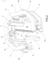
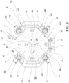
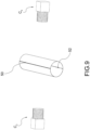
- the calibrated three-dimensional optical measuring apparatus 1 for the three-dimensional measurement of geometric parameters of a rope 2, comprises a frame 3' which defines and is arranged around a rope receiving cavity 29. Furthermore, a plurality of image acquisition devices C0, C1, C2, C3 is adapted to acquire a multiplicity of digital images of at least one region of an outer surface 21 of the rope 2. Such image acquisition devices C0, C1, C2, C3 are fixed to the frame 3' and are arranged around the rope 2 when the three-dimensional optical measuring apparatus 1 receives the rope 2 in the rope receiving cavity 29.
- the calibrated three-dimensional optical measuring apparatus 1 also comprises an electronic digital image processing device, configured to process the multiplicity of digital images and obtain a three-dimensional photogrammetric reconstruction of the points of the digital images of the rope acquired by the image acquisition devices C0, C1 , C2, C3.
- the image acquisition devices C0, C1, C2, C3 are arranged on the frame 3' circumferentially spaced apart from one another along such a circumferential direction C.
- a lighting device I0, I1, I2, I3 adapted to illuminate at least one region of the rope 2 is arranged between a pair of adjacent image acquisition devices C0, C1; C1, C2; C2, C3; C3, C1 along the circumferential direction C.
- the lighting device I0, I1, I2, I3 is arranged circumferentially spaced apart from the image acquisition devices C0, C1; C1, C2; C2, C3; C3, C1 immediately adjacent along the circumferential direction C.
- the lighting device I0, I1, I2, I3 is not arranged around the image acquisition device C0, C1; C1, C2; C2, C3; C3, i.e., it is not arranged concentrically around an image sensor of the image acquisition device C0, C1; C1, C2; C2, C3; C3, C1.
- the lighting device I0, I1, I2, I3 extends mainly along a direction parallel to the main extension direction of the rope 2.
- the electronic digital image processing device comprises a storage unit, in which the intrinsic and extrinsic calibration parameters of each image acquisition device C0, C1, C2, C3 are stored.
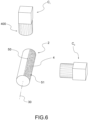
- the three-dimensional optical measuring apparatus 1 comprises an attachment device 4' adapted to constrain the three-dimensional optical measuring apparatus 1 to the rope in a relatively translatable manner with respect to the rope 2.
- an attachment device 4' comprises a plurality of revolution surfaces (for example wheels) joined to the frame 3' and adapted to slidably grip the rope 2. This allows to obtain a slidably self-supporting three-dimensional optical measuring apparatus on the rope 2.
- relatively translatable means that the apparatus can slide on the rope 2 or that the rope is moved with respect to the apparatus which is instead fixed with respect to a chosen reference system.
- Each revolution surface of the plurality of revolution surfaces is adapted to be adjustably spaced along a plane transverse or perpendicular to the main extension axis of the rope 2, so as to be able to accommodate ropes with different diameters between the plurality of revolution surfaces from time to time.
- the frame 3' comprises a casing 3 which defines and is arranged around the rope receiving cavity 29 and a support structure 10, joined to the casing 3.
- the image acquisition devices C0, C1, C2, C3 are fixed on the support structure 10.
- the support structure 10 comprises a joining region 11 releasably joined to the casing 3.
- the support structure 10 is spaced apart from the casing 3 in the remaining portion of the support structure, which is different from the joining region 11.
- a dampening element 5 is interposed, made of a material adapted to dampen the transmission of vibrations from the casing 3 to the support structure 10, for example a rubber or elastomeric material. This allows to prevent any vibrations applied to the casing 3 from being transmitted to the support structure 10, generating undesired vibrations on the image acquisition devices.
- the casing 3 and the support structure 10 are joined to form a single piece or form part of a single piece.
- the support structure 10 has an open annular shape and the casing 3 has a box-like shape.
- the casing 3 is arranged around the interior or the exterior of the support structure 10.
- the support structure comprises two open annular portions spaced apart in the axial direction X', which accommodate the image acquisition devices therebetween.
- the casing 3 comprises a casing tail wall 331 and a casing head wall 321, which close the casing side wall 31 close to the tail end 33 and the head end 32, respectively.
- At least one passage opening 6, 6', which is traversable by the rope 2 is obtained on each of such head wall 321 and tail wall 331.
- the tail wall 331 and the head wall 321 each comprise at least a first wall portion 321', 331' fixed and integral with the casing side wall 31 and a removable wall portion 321", 331" releasably fixed to the first wall portion 321', 331'.
- the removable wall portion 321'', 331" is not fixed to the first wall portion 321', 331', so as to leave a rope insertion opening 61 in the tail wall 331 and/or in the head wall 321.
- the rope insertion opening 61 is also communicating with the passage opening 6 to allow the insertion of the rope 2 into the passage opening 6, 6' by means of a relative movement between the casing 3 and the rope 2 perpendicular to the axial direction X' .
- the removable wall portion 321", 331" is fixed to the first wall portion 321', 331' so as to close the rope insertion opening 61.
- the removable wall portion 321'', 331'' at least partially defines the passage opening 6, 6'.
- the first wall portion 321', 331' comprises at least one sliding guide in which the removable wall portion 331", 321" is slidably engaged to switch from an extracted configuration, in which the rope insertion opening 61 is exposed, to an inserted configuration, in which the removable wall portion closes the rope insertion opening 61.
- the axial opening 28 facilitates the installation of the apparatus on the rope, making the operation of inserting the rope particularly easy to perform and allowing to install the apparatus from one rope to another quickly and effectively, without complicated fixing operations.
- the three-dimensional optical measuring apparatus 1 close to each rope passage opening 6, 6', the three-dimensional optical measuring apparatus 1 comprises a shielding wall 65 projecting from the head wall 321 or from the tail wall 331 and extending internally towards the rope receiving cavity 29, so as to at least partially shield the entrance of light from outside the casing towards the rope receiving cavity 29. This allows to further reduce the possible interference of external light towards the rope receiving cavity 29, thus ensuring greater robustness, precision, and 3D reconstruction reliability.
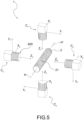
- the lighting device I0, I1, I2, I3 projects an illuminating beam B0, B1, B2, B3 having an opening cone with a vertex angle ⁇ 0, ⁇ 1, ⁇ 2, ⁇ 3 such as to prevent the light beam from intercepting a vision cone w0, w1, w2, w3 of each image acquisition device C0, C1, C2, C3 at least for a predefined distance D.
- a predefined distance D is calculated as a distance measured starting from the image sensor plane ⁇ of an image acquisition device C0, C1, C2, C3 and along a direction perpendicular to said image sensor plane ⁇ , towards the rope receiving cavity 29.
- the vision cone w0, w1, w2, w3 of each image acquisition device C0, C1, C2, C3 is not affected by any light beam of the lighting devices I0, I1, I2, I3. Furthermore, particularly advantageously, no light beam of the lighting devices directly affects the image sensor plane ⁇ of an image acquisition device C0, C1, C2, C3 arranged on the opposite side with respect to the rope 2.
- a material adapted to absorb the light electromagnetic radiation and reduce reflections is arranged on an inner surface 310 of the casing side wall 31.
- a material adapted to absorb the light electromagnetic radiation and reduce reflections for example a black paint, is arranged on an inner surface 310 of the casing side wall 31.
- Such an inner surface 310 faces the rope receiving cavity 29.
- the image acquisition devices C0, C1, C2, C3 comprise at least a first pair of image acquisition devices C0, C2 and a second pair of image acquisition devices C1, C3.
- the image acquisition devices of the first pair C0, C2 are arranged in a diametrically opposite manner and the image acquisition devices of the second pair C1, C3 are arranged in a diametrically opposite manner and are aligned along a perpendicular direction with respect to the alignment direction of the image acquisition devices of the first pair.
- At least one lighting device I0, I1, I2, I3 is interposed along the circumferential direction C and circumferentially spaced apart from the image acquisition devices .
- the lighting device I0, I1, I2, I3 is interposed between the image acquisition devices of each first or second pair and is circumferentially spaced apart from each of such image acquisition devices of each pair.
- the image acquisition devices C0, C1, C2, C3 are cameras with a matrix (two-dimensional) image sensor.
- the optics 400 of the cameras have optical foci which lie on a circumference offset by 90° and each optic 400 faces the center of the circumference.
- the rope is appropriately positioned inside the system, so that it is included in the field of vision of each camera and the dimensions of the radius of the circumference on which the cameras are placed, the focal distance of the optics, the dimensions of the camera sensors are adjusted so that they are adapted to the length of the sample measured along the axis, to the maximum measurable diameter or to the resolution to be obtained for the measuring system.
- the system is subjected to calibration, for example as soon as the assembly step of the image acquisition devices is completed, in order to obtain the intrinsic and extrinsic parameters of each device required for the subsequent steps for the three-dimensional photogrammetric reconstruction of the points of the acquired images, thus obtaining an intrinsically calibrated system.
- epipolar line of epipolar geometry which describes the geometric relationships and constraints which bind two 2D images of the same 3D scene captured by two cameras
- a point on an image subtends a line in the world, and the straight line in the world projected on another image, acquired by a camera placed in a different point of view, represents the epipolar line where the homologue of the point of the first image lies.
- the relationships between homologous points, epipolar lines and the geometry of the image acquisition system are described by means of suitable known algebraic relationships.
- the image acquisition device is a camera, the following are calculated:
- any point belonging to the rope is photogrammetrically reconstructed in a three-dimensional space starting from two images acquired by two different image acquisition devices which frame such a point of the rope or cable.
- the method for the three-dimensional optical measurement of geometric parameters of a rope 2 also comprises the steps of:
- roundness also means an index of the rope roundness.
- the operations for calculating the axis of the rope or cable include calculating the length of the axis and the orientation thereof.
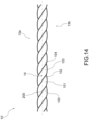
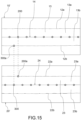
- 3D contour lines 70a, 70b, 70c, 70d of the outer surface of the rope or cable are calculated, in which each 3D contour line 70a, 70b, 70c, 70d is obtained as a regression which best approximates the first plurality of 3D contour points 60' or the second plurality of 3D contour points 61', 62'.
- 3D-multi-camera-reconstruction algorithms is used for the photogrammetric backprojection of the points in the three-dimensional space, some non-exhaustive examples are Triangulation algorithm or Disparity Map reprojection for 3D algorithm or combinations thereof.
- the respective digital images of the stationary or moving sample with respect to the cameras are detected.
- Each digital image is then corrected and purified from the effects of optical distortion by reconstructing, with the aid of the fi(r) function described above, the correct position of each point.
- homologous points mean each of the points on the digital images acquired by respective digital image acquisition systems, which represent the same point in the real three-dimensional world.
- homologous points can be searched on the images by means of known algorithms for the search of homologous points, such as Image correlation based, Edge based, Segment based, Adaptive windows, Coarse-to-fine, Dynamic programming, Markov random fields, graph cuts - Multi-baseline or combinations thereof.
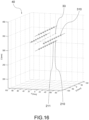
- the 3D midpoints 32' representative of the rope axis 30 are preferably obtained according to the following steps:
- the step is included for calculating an interpolated 3D mean axis 33', obtained as a regression which best approximates the plurality of 3D midpoints 32'.
- a regression is any regression curve and preferably a regression line.
- the point roundness of the rope or cable is measured as the ratio between at least the first diameter 80 and the second diameter 81.
- the rope diameter is calculated as the distance between the first contour point and the second contour point.
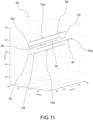
- the method of the present invention comprises the step of calculating the waviness of the rope or cable, i.e., a measurement of the surface homogeneity of the rope.
- the method comprises the steps of:
- the mean value of the sample standard deviations of the plurality of axis distances 82, 83, 84, 85 is a preferred index for the assessment of the waviness of the outer surface.
- the sets of the pairs of corresponding points belonging to the contour lines of the rope or cable and belonging to the axes of the rectified images in the three-dimensional space are back-projected, obtaining the three-dimensional representation of the points of the contour lines and the axis of the rope or cable referring with respect to a three-dimensional space.
- each pair of cameras detects a respective pair of digital images and in which at least one of the two images acquired by a first pair of cameras is different from at least one of the two images acquired by a second pair of cameras.
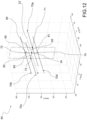
- the linearity of the axis of the rope or cable is measured, preferably by means of a calibrated three-dimensional optical measuring apparatus 1 described above, performing in addition to the steps for reconstructing the plurality of 3D midpoints 32' representative of the points of the rope axis, the following further steps:
- the interpolating curve is sampled to obtain a plurality of sampled 3D midpoints and an ideal 3D mean axis 35 is calculated as a regression line which best approximates said plurality of sampled 3D midpoints and then the distance 38 between the ideal 3D mean axis 35 and a sampled 3D midpoint 37 of said plurality of sampled 3D midpoints is calculated.
- the interpolating curve is any geometric curve, or for example, it is a linear curve in sections obtained by means of 3D interpolation of the 3D midpoints.
- the distance 38 between the ideal 3D mean axis 35 and a sampled 3D midpoint 37 of said plurality of sampled 3D midpoints is calculated as the length of the line joining the sampled 3D midpoint 37 and an intersection point between a plane perpendicular to the ideal 3D mean axis and passing through the sampled 3D midpoint and the ideal 3D mean axis.
- the pitch of the helix or coils of the rope is also measured, for example in the case where the rope is provided with strands or has a spiral or helical outer surface.
- steps a1), b1), c1) and c2) or in addition to steps a1) to g1) and c2) described in the previous paragraphs, with which the first mean axis 14 and the second mean axis 24 are calculated further steps are included for:
- a further step is included in which statistical variables (mean, variance, percentiles%) are calculated on the population of the distances (pitches) between the first 3D intersection points 210 and the second 3D intersection points 211, for example, the mean pitch is obtained as the mean of the distances between the first 3D intersection points 210 and the second 3D intersection points 211.
- the digital image is a rectified image, according to the known image rectification techniques in photogrammetry.
- the image acquired by a camera is subjected to rectification by means of a transformation process generally used to project multiple images onto a common two-dimensional surface, with a standard coordinate system, which modifies the perspective deformations of each image.
- the method according to the present invention is applied iteratively on portions of the rope 2 which are at least contiguous in sections along a direction H-H' parallel to a main dimension of the rope 2.
- a dimension can also have an indefinite length and such a method is consequently applied iteratively along said dimension of indefinite length.
- the method according to the present invention includes the simultaneous acquisition of at least two or more digital images, each acquired by a respective digital image acquisition device, of a portion of rope of predefined length. Therefore, it is not aimed at an acquisition of a single point or a single transversal line of the rope, but a portion of the rope extending for a predefined length along the rope axis is acquired.
- the method described in the preceding paragraphs can be directly loaded into the internal memory of a computer in the form of portions of software code adapted to implement the method according to what has been described up to now when the software is run on a computer.
- the calibrated three-dimensional optical measuring apparatus and the three-dimensional optical measurement method according to the present invention allow to reconstruct three-dimensional measurements of ropes or cables or parts of ropes or cables which are stationary or moving and therefore to perform measurements and quality checks in a non-invasive and non-destructive manner on the rope or cable, with continuity along the entire length of the object, without an operator needing to perform manual measurements, without requiring stopping the movement of the rope or cable and in a precise and accurate manner.
- an attachment device 4' adapted to constrain the three-dimensional optical measuring apparatus to the rope in a relatively translatable manner with respect to the rope 2 allows the entire apparatus to be moved, thus allowing to calculate the geometric 3D parameters while the apparatus is being moved along the rope.
- this is particularly advantageous as it prevents having to slide the rope and allows the apparatus to be used in a variety of situations in which the rope is fixed and the apparatus slides on the rope (for example for monitoring bridge ropes or supporting ropes of cableways or cables at high altitudes, and the like) or in which the apparatus is held fixed with respect to a reference on the ground and the rope slides relative to the apparatus (for example, for monitoring lifting ropes or hauling ropes of cable cars and the like).
- the installation operation on the rope is simple and fast to obtain, allowing to further facilitate the mobile installation of the apparatus.
- a support structure 10 spaced apart from the casing 3 and joined only at a joining region 11, possibly provided with a dampening element allows to limit any vibrations, preventing any vibrations towards the image acquisition devices during the movement of the apparatus with respect to the rope.
- the system allows to obtain the linearity of the axis of the rope or cable, the measurement of the diameter and roundness of an object approximating a rotating body and the measurement of the pitch of coils present on the surface of the rope or cable, starting only from the images of the outer surface of the object itself and for indefinite lengths, simply by making the rope relatively move with respect to the apparatus. For example, this is useful for the dimensional verification of ropes or cables of considerable length.
- the apparatus is capable of automatically performing the measurements of the geometric parameters even in the presence of difficult environmental conditions from the point of view of the rope lighting, such as measurements in environments contaminated by fumes, gases, dusts, weathering. Furthermore, the system allows to perform measurements continuously and irrespective of the dimensions and the material forming the outer and inner surface of the rope.
- the apparatus does not require further calibration operations before each measurement, as however disadvantageously occurs for non-calibrated optical measuring systems.
- the three-dimensional reconstruction of the plurality of contour 3D points, and therefore the three-dimensional measurement of the rope parameters allows to overcome the problems of perspective localization between rope and camera, since the rope contours will always be reconstructed in a calibrated three-dimensional space and it is always possible to calculate the parameters regardless of the relative position between camera and rope during image acquisition.
- the use of synchronized cameras preferably with two-dimensional matrix image sensor, allows to acquire images of entire portions of rope at the same instant with subsequent photogrammetric reconstruction, reducing or even eliminating measurement errors due to any vibrations of the rope, around an axis perpendicular to the rope axis.
Landscapes
- Physics & Mathematics (AREA)
- General Physics & Mathematics (AREA)
- Engineering & Computer Science (AREA)
- Computer Vision & Pattern Recognition (AREA)
- Theoretical Computer Science (AREA)
- Geometry (AREA)
- Quality & Reliability (AREA)
- Life Sciences & Earth Sciences (AREA)
- Health & Medical Sciences (AREA)
- Chemical & Material Sciences (AREA)
- Analytical Chemistry (AREA)
- Biochemistry (AREA)
- General Health & Medical Sciences (AREA)
- Immunology (AREA)
- Pathology (AREA)
- Length Measuring Devices By Optical Means (AREA)
Applications Claiming Priority (2)
| Application Number | Priority Date | Filing Date | Title |
|---|---|---|---|
| IT102020000001057A IT202000001057A1 (it) | 2020-01-21 | 2020-01-21 | Apparato mobile di misura ottico tridimensionale per funi con dispositivo di attacco su fune |
| PCT/IB2021/050445 WO2021148971A1 (en) | 2020-01-21 | 2021-01-21 | Three-dimensional optical measuring mobile apparatus for ropes with rope attachment device |
Publications (2)
| Publication Number | Publication Date |
|---|---|
| EP4094040A1 EP4094040A1 (en) | 2022-11-30 |
| EP4094040B1 true EP4094040B1 (en) | 2024-07-24 |
Family
ID=70228706
Family Applications (1)
| Application Number | Title | Priority Date | Filing Date |
|---|---|---|---|
| EP21705603.5A Active EP4094040B1 (en) | 2020-01-21 | 2021-01-21 | Three-dimensional optical measuring mobile apparatus for ropes with rope attachment device |
Country Status (14)
| Country | Link |
|---|---|
| US (2) | US12352555B2 (pl) |
| EP (1) | EP4094040B1 (pl) |
| KR (1) | KR20220133231A (pl) |
| CN (1) | CN115298513A (pl) |
| AU (1) | AU2021210228A1 (pl) |
| BR (1) | BR112022014336A2 (pl) |
| CA (1) | CA3168476A1 (pl) |
| CL (1) | CL2022001981A1 (pl) |
| ES (1) | ES2993647T3 (pl) |
| FI (1) | FI4094040T3 (pl) |
| IT (1) | IT202000001057A1 (pl) |
| PL (1) | PL4094040T3 (pl) |
| PT (1) | PT4094040T (pl) |
| WO (1) | WO2021148971A1 (pl) |
Families Citing this family (7)
| Publication number | Priority date | Publication date | Assignee | Title |
|---|---|---|---|---|
| CN113819303B (zh) * | 2021-09-30 | 2022-11-11 | 陕西华山路桥集团有限公司 | 一种管道抗拉增强装置及其使用方法 |
| WO2023090952A1 (ko) | 2021-11-19 | 2023-05-25 | 주식회사 엘지에너지솔루션 | 이차 전지 및 배터리 팩 |
| CN114414487B (zh) * | 2022-01-19 | 2024-04-16 | 北京科技大学设计研究院有限公司 | 一种二维与三维融合的圆钢表面成像系统 |
| FI20235604A1 (fi) * | 2023-05-30 | 2024-12-01 | Konecranes Global Oy | Synteettisen köyden kunnonvalvontalaite |
| CN116734769B (zh) * | 2023-08-14 | 2023-12-01 | 宁德时代新能源科技股份有限公司 | 圆柱电芯的圆柱度检测装置及检测方法 |
| CN117697796B (zh) * | 2024-02-06 | 2024-05-03 | 广东省公路建设有限公司湾区特大桥养护技术中心 | 一种桥梁缆索表观及内部综合检测机器人 |
| CN119728942B (zh) * | 2024-12-19 | 2025-09-09 | 同济大学 | 一种生成动态多目虚拟相机的装置 |
Family Cites Families (22)
| Publication number | Priority date | Publication date | Assignee | Title |
|---|---|---|---|---|
| DE3641816A1 (de) * | 1986-12-06 | 1988-06-16 | Robert Prof Dr Ing Massen | Verfahren und anordnung zur messung und/oder ueberwachung von eigenschaften von garnen und seilen |
| US20050088515A1 (en) * | 2003-10-23 | 2005-04-28 | Geng Z. J. | Camera ring for three-dimensional (3D) surface imaging |
| WO2006034144A2 (en) * | 2004-09-18 | 2006-03-30 | The Ohio Willow Wood Company | Apparatus for determining the three dimensional shape of an object |
| US8105442B2 (en) * | 2008-02-28 | 2012-01-31 | Welaptega Marine Limited | Tubular measurement system |
| JP5633719B2 (ja) * | 2009-09-18 | 2014-12-03 | 学校法人福岡工業大学 | 三次元情報計測装置および三次元情報計測方法 |
| EP2383566B1 (de) * | 2010-04-28 | 2013-10-23 | Winspect GmbH | System und Verfahren zur Prüfung von Seilen |
| WO2011163359A2 (en) * | 2010-06-23 | 2011-12-29 | The Trustees Of Dartmouth College | 3d scanning laser systems and methods for determining surface geometry of an immersed object in a transparent cylindrical glass tank |
| DE202011001846U1 (de) * | 2011-01-24 | 2012-04-30 | Liebherr-Components Biberach Gmbh | Vorrichtung zur Erkennung der Ablegereife eines hochfesten Faserseils beim Einsatz an Hebezeugen |
| JP5717246B2 (ja) * | 2011-02-04 | 2015-05-13 | 西松建設株式会社 | 点検装置 |
| US20150346115A1 (en) | 2014-05-30 | 2015-12-03 | Eric J. Seibel | 3d optical metrology of internal surfaces |
| US9535026B2 (en) * | 2014-12-09 | 2017-01-03 | Tech4Imaging Llc | Electrical capacitance volume tomography sensor for inspection of post-tensioned tendons |
| CN105633577B (zh) * | 2016-01-25 | 2019-01-01 | 西安电子科技大学 | 薄膜反射面边界索位置微调与索力测量装置及方法 |
| ITUB20160775A1 (it) * | 2016-02-16 | 2017-08-16 | Redaelli Tecna Spa | Dispositivo per la misura in continuo ed in automatico dei parametri geometrici di una fune |
| JP6875836B2 (ja) * | 2016-11-29 | 2021-05-26 | 株式会社明電舎 | ワイヤロープ計測装置及び方法 |
| US10267725B2 (en) * | 2017-06-02 | 2019-04-23 | Evolution Engineering Inc. | Surface profile measurement system |
| CN107121079B (zh) | 2017-06-14 | 2019-11-22 | 华中科技大学 | 一种基于单目视觉的曲面高度信息测量装置及方法 |
| CN107764839B (zh) * | 2017-10-12 | 2020-05-05 | 中南大学 | 一种基于机器视觉的钢丝绳表面缺陷在线检测方法及装置 |
| EP3810970B1 (en) * | 2018-06-25 | 2023-04-19 | Oetiker NY, Inc. | Connection verifier |
| CN208705273U (zh) * | 2018-09-12 | 2019-04-05 | 中国计量大学 | 基于多回路励磁和图像分析的钢丝绳无损探伤传感装置 |
| EP3654039B1 (en) * | 2018-11-16 | 2022-08-24 | Roche Diagnostics GmbH | Automated tube handling |
| US12333739B2 (en) * | 2019-04-18 | 2025-06-17 | Standard Cognition, Corp. | Machine learning-based re-identification of shoppers in a cashier-less store for autonomous checkout |
| US12253533B2 (en) * | 2019-10-31 | 2025-03-18 | Siemens Healthcare Diagnostics Inc. | Methods and apparatus providing calibration of background illumination for sample and/or sample container characterization |
-
2020
- 2020-01-21 IT IT102020000001057A patent/IT202000001057A1/it unknown
-
2021
- 2021-01-21 FI FIEP21705603.5T patent/FI4094040T3/fi active
- 2021-01-21 WO PCT/IB2021/050445 patent/WO2021148971A1/en not_active Ceased
- 2021-01-21 EP EP21705603.5A patent/EP4094040B1/en active Active
- 2021-01-21 KR KR1020227028847A patent/KR20220133231A/ko active Pending
- 2021-01-21 CA CA3168476A patent/CA3168476A1/en active Pending
- 2021-01-21 PT PT217056035T patent/PT4094040T/pt unknown
- 2021-01-21 BR BR112022014336A patent/BR112022014336A2/pt unknown
- 2021-01-21 PL PL21705603.5T patent/PL4094040T3/pl unknown
- 2021-01-21 ES ES21705603T patent/ES2993647T3/es active Active
- 2021-01-21 CN CN202180023278.9A patent/CN115298513A/zh active Pending
- 2021-01-21 AU AU2021210228A patent/AU2021210228A1/en active Pending
- 2021-01-21 US US17/759,053 patent/US12352555B2/en active Active
-
2022
- 2022-07-21 CL CL2022001981A patent/CL2022001981A1/es unknown
-
2025
- 2025-05-21 US US19/214,444 patent/US20250283714A1/en active Pending
Also Published As
| Publication number | Publication date |
|---|---|
| PL4094040T3 (pl) | 2024-12-16 |
| KR20220133231A (ko) | 2022-10-04 |
| US12352555B2 (en) | 2025-07-08 |
| IT202000001057A1 (it) | 2021-07-21 |
| CA3168476A1 (en) | 2021-07-29 |
| US20250283714A1 (en) | 2025-09-11 |
| BR112022014336A2 (pt) | 2022-10-04 |
| EP4094040A1 (en) | 2022-11-30 |
| AU2021210228A1 (en) | 2022-08-11 |
| PT4094040T (pt) | 2024-09-05 |
| US20230040446A1 (en) | 2023-02-09 |
| FI4094040T3 (fi) | 2024-10-30 |
| CL2022001981A1 (es) | 2023-01-27 |
| ES2993647T3 (en) | 2025-01-03 |
| CN115298513A (zh) | 2022-11-04 |
| WO2021148971A1 (en) | 2021-07-29 |
Similar Documents
| Publication | Publication Date | Title |
|---|---|---|
| EP4094040B1 (en) | Three-dimensional optical measuring mobile apparatus for ropes with rope attachment device | |
| US20230106282A1 (en) | Three-dimensional optical measuring apparatus for ropes with lighting device | |
| US5362962A (en) | Method and apparatus for measuring pipeline corrosion | |
| US8345094B2 (en) | System and method for inspecting the interior surface of a pipeline | |
| US20040021858A1 (en) | Apparatus and method for detecting pipelwe defects | |
| EP3177902B1 (en) | Methods and apparatus for determining geometric properties of optical fiber preforms | |
| EP3853553B1 (en) | Three-dimensional optical measurement method for ropes or cables and system | |
| Wu et al. | Noncontact laser inspection based on a PSD for the inner surface of minidiameter pipes | |
| RU2757474C2 (ru) | Сканирующее устройство и способ измерения и обследования круглых отверстий в прозрачных жидкостях в среде с ионизирующим излучением | |
| US7342654B2 (en) | Detection of impurities in cylindrically shaped transparent media | |
| US9772259B2 (en) | Method for calibrating an X-ray testing system for a tire type and method for checking the position of cords in a tire | |
| Lavrinov et al. | The Analysis of the Measurement System Accuracy Based on 2D Laser Optical Micrometer When Measuring API Pipe Thread | |
| Lavrinov et al. | The Analysis of the Measurement System Accuracy Based on 2D Laser Optical Micrometer When Measuring API Pipe Thread Pitch and Height | |
| Li et al. | Multi-ring beam sensing system for three-dimensional measurement of the narrow inner surface profiles | |
| US20230334731A1 (en) | Method and device for correcting coherence tomography images | |
| Camacho-Reyes et al. | Characterization of non-planar crack tip displacement fields using Characterization of non planar crack tip displacement fields using a differential geometry approach in combination with 3D digital image correlation | |
| Segura¹ et al. | Measurement by 3D Scanning | |
| JPH06229742A (ja) | 円筒状物体の曲りと外径と真円度の同時測定方法 | |
| WO2023238451A1 (ja) | 部品検査方法および部品検査装置 |
Legal Events
| Date | Code | Title | Description |
|---|---|---|---|
| STAA | Information on the status of an ep patent application or granted ep patent |
Free format text: STATUS: UNKNOWN |
|
| STAA | Information on the status of an ep patent application or granted ep patent |
Free format text: STATUS: THE INTERNATIONAL PUBLICATION HAS BEEN MADE |
|
| PUAI | Public reference made under article 153(3) epc to a published international application that has entered the european phase |
Free format text: ORIGINAL CODE: 0009012 |
|
| STAA | Information on the status of an ep patent application or granted ep patent |
Free format text: STATUS: REQUEST FOR EXAMINATION WAS MADE |
|
| 17P | Request for examination filed |
Effective date: 20220719 |
|
| AK | Designated contracting states |
Kind code of ref document: A1 Designated state(s): AL AT BE BG CH CY CZ DE DK EE ES FI FR GB GR HR HU IE IS IT LI LT LU LV MC MK MT NL NO PL PT RO RS SE SI SK SM TR |
|
| DAV | Request for validation of the european patent (deleted) | ||
| DAX | Request for extension of the european patent (deleted) | ||
| P01 | Opt-out of the competence of the unified patent court (upc) registered |
Effective date: 20230619 |
|
| GRAP | Despatch of communication of intention to grant a patent |
Free format text: ORIGINAL CODE: EPIDOSNIGR1 |
|
| STAA | Information on the status of an ep patent application or granted ep patent |
Free format text: STATUS: GRANT OF PATENT IS INTENDED |
|
| RIC1 | Information provided on ipc code assigned before grant |
Ipc: G01B 21/04 20060101ALI20240202BHEP Ipc: G01B 11/24 20060101ALI20240202BHEP Ipc: G01B 11/10 20060101ALI20240202BHEP Ipc: G01B 5/00 20060101ALI20240202BHEP Ipc: G06T 7/593 20170101ALI20240202BHEP Ipc: G06T 7/60 20170101ALI20240202BHEP Ipc: G06T 7/00 20170101ALI20240202BHEP Ipc: G01B 11/245 20060101AFI20240202BHEP |
|
| RIN1 | Information on inventor provided before grant (corrected) |
Inventor name: NEWTON, CHRISTOPHER JOHN Inventor name: VANLANDEGHEM, BART Inventor name: BONETTI, CRISTIANO |
|
| INTG | Intention to grant announced |
Effective date: 20240305 |
|
| RAP3 | Party data changed (applicant data changed or rights of an application transferred) |
Owner name: BRIDON INTERNATIONAL LTD |
|
| GRAS | Grant fee paid |
Free format text: ORIGINAL CODE: EPIDOSNIGR3 |
|
| GRAA | (expected) grant |
Free format text: ORIGINAL CODE: 0009210 |
|
| STAA | Information on the status of an ep patent application or granted ep patent |
Free format text: STATUS: THE PATENT HAS BEEN GRANTED |
|
| AK | Designated contracting states |
Kind code of ref document: B1 Designated state(s): AL AT BE BG CH CY CZ DE DK EE ES FI FR GB GR HR HU IE IS IT LI LT LU LV MC MK MT NL NO PL PT RO RS SE SI SK SM TR |
|
| REG | Reference to a national code |
Ref country code: GB Ref legal event code: FG4D |
|
| REG | Reference to a national code |
Ref country code: CH Ref legal event code: EP |
|
| REG | Reference to a national code |
Ref country code: IE Ref legal event code: FG4D Ref country code: DE Ref legal event code: R096 Ref document number: 602021016119 Country of ref document: DE |
|
| REG | Reference to a national code |
Ref country code: PT Ref legal event code: SC4A Ref document number: 4094040 Country of ref document: PT Date of ref document: 20240905 Kind code of ref document: T Free format text: AVAILABILITY OF NATIONAL TRANSLATION Effective date: 20240829 |
|
| REG | Reference to a national code |
Ref country code: EE Ref legal event code: FG4A Ref document number: E024516 Country of ref document: EE Effective date: 20240822 |
|
| REG | Reference to a national code |
Ref country code: NL Ref legal event code: FP |
|
| REG | Reference to a national code |
Ref country code: SE Ref legal event code: TRGR |
|
| REG | Reference to a national code |
Ref country code: FI Ref legal event code: FGE |
|
| REG | Reference to a national code |
Ref country code: LT Ref legal event code: MG9D |
|
| REG | Reference to a national code |
Ref country code: ES Ref legal event code: FG2A Ref document number: 2993647 Country of ref document: ES Kind code of ref document: T3 Effective date: 20250103 |
|
| PG25 | Lapsed in a contracting state [announced via postgrant information from national office to epo] |
Ref country code: GR Free format text: LAPSE BECAUSE OF FAILURE TO SUBMIT A TRANSLATION OF THE DESCRIPTION OR TO PAY THE FEE WITHIN THE PRESCRIBED TIME-LIMIT Effective date: 20241025 |
|
| PG25 | Lapsed in a contracting state [announced via postgrant information from national office to epo] |
Ref country code: BG Free format text: LAPSE BECAUSE OF FAILURE TO SUBMIT A TRANSLATION OF THE DESCRIPTION OR TO PAY THE FEE WITHIN THE PRESCRIBED TIME-LIMIT Effective date: 20240724 |
|
| PG25 | Lapsed in a contracting state [announced via postgrant information from national office to epo] |
Ref country code: LV Free format text: LAPSE BECAUSE OF FAILURE TO SUBMIT A TRANSLATION OF THE DESCRIPTION OR TO PAY THE FEE WITHIN THE PRESCRIBED TIME-LIMIT Effective date: 20240724 |
|
| PG25 | Lapsed in a contracting state [announced via postgrant information from national office to epo] |
Ref country code: IS Free format text: LAPSE BECAUSE OF FAILURE TO SUBMIT A TRANSLATION OF THE DESCRIPTION OR TO PAY THE FEE WITHIN THE PRESCRIBED TIME-LIMIT Effective date: 20241124 |
|
| PG25 | Lapsed in a contracting state [announced via postgrant information from national office to epo] |
Ref country code: HR Free format text: LAPSE BECAUSE OF FAILURE TO SUBMIT A TRANSLATION OF THE DESCRIPTION OR TO PAY THE FEE WITHIN THE PRESCRIBED TIME-LIMIT Effective date: 20240724 |
|
| PG25 | Lapsed in a contracting state [announced via postgrant information from national office to epo] |
Ref country code: RS Free format text: LAPSE BECAUSE OF FAILURE TO SUBMIT A TRANSLATION OF THE DESCRIPTION OR TO PAY THE FEE WITHIN THE PRESCRIBED TIME-LIMIT Effective date: 20241024 |
|
| PG25 | Lapsed in a contracting state [announced via postgrant information from national office to epo] |
Ref country code: RS Free format text: LAPSE BECAUSE OF FAILURE TO SUBMIT A TRANSLATION OF THE DESCRIPTION OR TO PAY THE FEE WITHIN THE PRESCRIBED TIME-LIMIT Effective date: 20241024 Ref country code: LV Free format text: LAPSE BECAUSE OF FAILURE TO SUBMIT A TRANSLATION OF THE DESCRIPTION OR TO PAY THE FEE WITHIN THE PRESCRIBED TIME-LIMIT Effective date: 20240724 Ref country code: IS Free format text: LAPSE BECAUSE OF FAILURE TO SUBMIT A TRANSLATION OF THE DESCRIPTION OR TO PAY THE FEE WITHIN THE PRESCRIBED TIME-LIMIT Effective date: 20241124 Ref country code: HR Free format text: LAPSE BECAUSE OF FAILURE TO SUBMIT A TRANSLATION OF THE DESCRIPTION OR TO PAY THE FEE WITHIN THE PRESCRIBED TIME-LIMIT Effective date: 20240724 Ref country code: GR Free format text: LAPSE BECAUSE OF FAILURE TO SUBMIT A TRANSLATION OF THE DESCRIPTION OR TO PAY THE FEE WITHIN THE PRESCRIBED TIME-LIMIT Effective date: 20241025 Ref country code: BG Free format text: LAPSE BECAUSE OF FAILURE TO SUBMIT A TRANSLATION OF THE DESCRIPTION OR TO PAY THE FEE WITHIN THE PRESCRIBED TIME-LIMIT Effective date: 20240724 |
|
| PGFP | Annual fee paid to national office [announced via postgrant information from national office to epo] |
Ref country code: NL Payment date: 20250121 Year of fee payment: 5 |
|
| PGFP | Annual fee paid to national office [announced via postgrant information from national office to epo] |
Ref country code: PT Payment date: 20250109 Year of fee payment: 5 Ref country code: DE Payment date: 20250121 Year of fee payment: 5 |
|
| PG25 | Lapsed in a contracting state [announced via postgrant information from national office to epo] |
Ref country code: RO Free format text: LAPSE BECAUSE OF FAILURE TO SUBMIT A TRANSLATION OF THE DESCRIPTION OR TO PAY THE FEE WITHIN THE PRESCRIBED TIME-LIMIT Effective date: 20240724 Ref country code: DK Free format text: LAPSE BECAUSE OF FAILURE TO SUBMIT A TRANSLATION OF THE DESCRIPTION OR TO PAY THE FEE WITHIN THE PRESCRIBED TIME-LIMIT Effective date: 20240724 Ref country code: SM Free format text: LAPSE BECAUSE OF FAILURE TO SUBMIT A TRANSLATION OF THE DESCRIPTION OR TO PAY THE FEE WITHIN THE PRESCRIBED TIME-LIMIT Effective date: 20240724 |
|
| PGFP | Annual fee paid to national office [announced via postgrant information from national office to epo] |
Ref country code: FI Payment date: 20250124 Year of fee payment: 5 |
|
| PGFP | Annual fee paid to national office [announced via postgrant information from national office to epo] |
Ref country code: ES Payment date: 20250226 Year of fee payment: 5 |
|
| PGFP | Annual fee paid to national office [announced via postgrant information from national office to epo] |
Ref country code: IE Payment date: 20250130 Year of fee payment: 5 Ref country code: SE Payment date: 20250121 Year of fee payment: 5 |
|
| PGFP | Annual fee paid to national office [announced via postgrant information from national office to epo] |
Ref country code: NO Payment date: 20250124 Year of fee payment: 5 |
|
| PGFP | Annual fee paid to national office [announced via postgrant information from national office to epo] |
Ref country code: AT Payment date: 20250417 Year of fee payment: 5 Ref country code: EE Payment date: 20250116 Year of fee payment: 5 Ref country code: CH Payment date: 20250201 Year of fee payment: 5 Ref country code: BE Payment date: 20250121 Year of fee payment: 5 |
|
| PG25 | Lapsed in a contracting state [announced via postgrant information from national office to epo] |
Ref country code: CZ Free format text: LAPSE BECAUSE OF FAILURE TO SUBMIT A TRANSLATION OF THE DESCRIPTION OR TO PAY THE FEE WITHIN THE PRESCRIBED TIME-LIMIT Effective date: 20240724 |
|
| PGFP | Annual fee paid to national office [announced via postgrant information from national office to epo] |
Ref country code: FR Payment date: 20250128 Year of fee payment: 5 Ref country code: PL Payment date: 20250110 Year of fee payment: 5 |
|
| REG | Reference to a national code |
Ref country code: DE Ref legal event code: R097 Ref document number: 602021016119 Country of ref document: DE |
|
| PG25 | Lapsed in a contracting state [announced via postgrant information from national office to epo] |
Ref country code: SK Free format text: LAPSE BECAUSE OF FAILURE TO SUBMIT A TRANSLATION OF THE DESCRIPTION OR TO PAY THE FEE WITHIN THE PRESCRIBED TIME-LIMIT Effective date: 20240724 |
|
| PGFP | Annual fee paid to national office [announced via postgrant information from national office to epo] |
Ref country code: IT Payment date: 20250129 Year of fee payment: 5 Ref country code: GB Payment date: 20250128 Year of fee payment: 5 |
|
| PGFP | Annual fee paid to national office [announced via postgrant information from national office to epo] |
Ref country code: TR Payment date: 20250113 Year of fee payment: 5 |
|
| PLBE | No opposition filed within time limit |
Free format text: ORIGINAL CODE: 0009261 |
|
| STAA | Information on the status of an ep patent application or granted ep patent |
Free format text: STATUS: NO OPPOSITION FILED WITHIN TIME LIMIT |
|
| 26N | No opposition filed |
Effective date: 20250425 |
|
| PG25 | Lapsed in a contracting state [announced via postgrant information from national office to epo] |
Ref country code: MC Free format text: LAPSE BECAUSE OF FAILURE TO SUBMIT A TRANSLATION OF THE DESCRIPTION OR TO PAY THE FEE WITHIN THE PRESCRIBED TIME-LIMIT Effective date: 20240724 Ref country code: LU Free format text: LAPSE BECAUSE OF NON-PAYMENT OF DUE FEES Effective date: 20250121 |
|
| REG | Reference to a national code |
Ref country code: CH Ref legal event code: U11 Free format text: ST27 STATUS EVENT CODE: U-0-0-U10-U11 (AS PROVIDED BY THE NATIONAL OFFICE) Effective date: 20260201 |