EP4093979B1 - Stellantrieb mit versetztem versorgungsanschluss - Google Patents
Stellantrieb mit versetztem versorgungsanschluss Download PDFInfo
- Publication number
- EP4093979B1 EP4093979B1 EP21700952.1A EP21700952A EP4093979B1 EP 4093979 B1 EP4093979 B1 EP 4093979B1 EP 21700952 A EP21700952 A EP 21700952A EP 4093979 B1 EP4093979 B1 EP 4093979B1
- Authority
- EP
- European Patent Office
- Prior art keywords
- actuator
- connection port
- strut
- duct
- plane
- Prior art date
- Legal status (The legal status is an assumption and is not a legal conclusion. Google has not performed a legal analysis and makes no representation as to the accuracy of the status listed.)
- Active
Links
Images
Classifications
-
- B—PERFORMING OPERATIONS; TRANSPORTING
- B64—AIRCRAFT; AVIATION; COSMONAUTICS
- B64C—AEROPLANES; HELICOPTERS
- B64C25/00—Alighting gear
- B64C25/02—Undercarriages
- B64C25/08—Undercarriages non-fixed, e.g. jettisonable
- B64C25/10—Undercarriages non-fixed, e.g. jettisonable retractable, foldable, or the like
- B64C25/18—Operating mechanisms
- B64C25/22—Operating mechanisms fluid
-
- F—MECHANICAL ENGINEERING; LIGHTING; HEATING; WEAPONS; BLASTING
- F15—FLUID-PRESSURE ACTUATORS; HYDRAULICS OR PNEUMATICS IN GENERAL
- F15B—SYSTEMS ACTING BY MEANS OF FLUIDS IN GENERAL; FLUID-PRESSURE ACTUATORS, e.g. SERVOMOTORS; DETAILS OF FLUID-PRESSURE SYSTEMS, NOT OTHERWISE PROVIDED FOR
- F15B15/00—Fluid-actuated devices for displacing a member from one position to another; Gearing associated therewith
- F15B15/08—Characterised by the construction of the motor unit
- F15B15/14—Characterised by the construction of the motor unit of the straight-cylinder type
- F15B15/1423—Component parts; Constructional details
- F15B15/1428—Cylinders
-
- F—MECHANICAL ENGINEERING; LIGHTING; HEATING; WEAPONS; BLASTING
- F15—FLUID-PRESSURE ACTUATORS; HYDRAULICS OR PNEUMATICS IN GENERAL
- F15B—SYSTEMS ACTING BY MEANS OF FLUIDS IN GENERAL; FLUID-PRESSURE ACTUATORS, e.g. SERVOMOTORS; DETAILS OF FLUID-PRESSURE SYSTEMS, NOT OTHERWISE PROVIDED FOR
- F15B15/00—Fluid-actuated devices for displacing a member from one position to another; Gearing associated therewith
- F15B15/08—Characterised by the construction of the motor unit
- F15B15/14—Characterised by the construction of the motor unit of the straight-cylinder type
- F15B15/149—Fluid interconnections, e.g. fluid connectors, passages
Definitions
- the present invention relates to an actuator comprising at least one remote power supply port.
- the actuator is for example a cylinder intended to equip an aircraft.
- Aircraft are known whose landing gear is mounted to be movable between a deployed position and a retracted position and comprises an unlocking actuator allowing the movement of the gear from the retracted position to the deployed position.
- the unlocking actuator is generally a hydraulic cylinder comprising a tubular body in which a rod is slidably mounted.
- the rod is integral with a piston which separates an interior volume of the body into two chambers isolated from each other. Two connection ports make it possible to introduce or evacuate a fluid into one or the other of the chambers and thus move the rod.
- connection ports are offset so as to be away from the cylinder body.
- Each connection port is connected to the cylinder body by a conduit opening into one of the chambers.
- the conduits are traditionally channels that have been drilled into a solid body extending out from an external surface of the cylinder body.
- the body and the solid body are generally manufactured by forging or by assembling previously machined parts.
- the invention therefore aims to propose an actuator with remote power supply ports making it possible to at least partially overcome the aforementioned problems.
- an actuator comprising a body extending along a central axis and at least one first remote connection port.
- the connection port is connected to the body by a first conduit extending projecting from said body.
- the first connection port is mechanically connected to the body by at least a first member and a second member, the first member and the second member extending from the first connection port to respectively a first section of the body and a second section of the body axially distant from the first section.
- connection port to the body makes it possible to limit the weight of the actuator, the members leaving spaces between them free of material, while guaranteeing the vibration and pressure resistance of the connection port.
- the actuator comprises a second remote connection port connected to the body by a second conduit.
- the second connection port is mechanically connected to the body by at least a third member and a fourth member, the third member and the fourth member extending from the second connection port to two portions of the body axially distant from each other.
- the second connection port is aligned with the first connection port, and the fourth member and the second member have a common section.
- At least one of the third member and the fourth member is arranged to mechanically connect a portion of the first conduit to the body.
- At least two of the members have a portion extending along a median longitudinal plane of the body.
- the first duct extends along the median longitudinal plane of the body.
- first member and the second member have a substantially identical length.
- At least one of the members has a V-shaped cross-section.
- the actuator comprises a veil ensuring a mechanical connection between the body, each conduit, and the members.
- the veil has drainage holes.
- the actuator comprises at least one rib extending on one side of the veil from one of the conduits to one of the members.
- each conduit and each connection port form a single piece obtained by additive manufacturing.
- the invention also relates to a landing gear having at least one extended position and one retracted position, and comprising such an actuator for locking or unlocking the landing gear in at least one of its two positions.
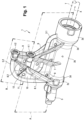
- an actuator 1 comprises, according to a particular embodiment of the invention, a generally tubular body 2 extending along a central axis X.
- the body 2 successively comprises a first end section 2a, an intermediate section 2b and a second end section 2c each having an external surface of cylindrical shape extending along the axis X.
- the first end section 2a and the second end section 2c are connected to the intermediate section 2b via connecting portions 2d having truncated cone-shaped outer surfaces whose small bases are connected to the outer surface of the intermediate section 2b and whose large bases are connected to the outer surfaces of the first end section 2a and the second end section 2c.
- the body 2 forms the main body of a double-acting hydraulic cylinder and defines in a manner known per se an interior volume inside which a rod T is slidably mounted along the axis X and extends projecting from the first end section 2a of the body 2.
- the rod is secured to a piston separating the interior volume of the body 2 into two chambers isolated from each other.
- the second end section 2c is connected to a bearing 3 for articulating the actuator 1 to the structure of an aircraft.
- the body 2 thus forms a connection interface to the rod of the actuator 1 and the bearing 3 forms a connection interface to the structure of the aircraft.
- the actuator 1 comprises a first connection port 4.1 and a second connection port 4.2 for introducing or discharging a fluid into one or the other of the two chambers and thus moving the rod.
- the first connection port 4.1 and the second connection port 4.2 are substantially identical and each comprise a tubular part delimiting a channel arranged to receive an end portion of a connection conduit.
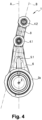
- the first connection port 4.1 and the second connection port 4.2 extend substantially parallel to the central axis X of the body 2 and their free ends extend substantially in the same plane orthogonal to said axis X so that the two connection ports are aligned with each other.
- the distance separating the first connection port 4.1 from the body 2 is less than that separating the second connection port 4.2 from said body 2 so that the first connection port 4.1 extends between the second connection port 4.2 and the body 2 in all of the figures.
- a first conduit 5.1 connects the first connection port 4.1 to the first end section 2a of the body 2 from which the rod of the actuator projects.
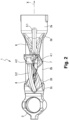
- the neutral fiber of the first conduit 5.1 extends substantially over its entire length in a plane A comprising the central axis X of the body 2 (the plane A thus constitutes a median longitudinal plane of the body 2).
- the first conduit 5.1 successively comprises a quarter-circle portion, one end of which opens into one of the chambers of the body 2, a first rectilinear portion substantially parallel to the X axis, a semicircular portion and a second rectilinear portion, extending parallel to the central X axis opposite the first rectilinear portion, one end of which opens into the first connection port 4.1.
- a second conduit 5.2 connects the second connection port 4.2 to the second end section 2c of the body 2 carrying the bearing 3.
- the second conduit 5.2 comprises a first rectilinear portion substantially perpendicular to the central axis X of the body 2 and one end of which opens into the other of the chambers of the body 2, and a quarter-circle portion one end of which opens into the second connection port 4.2.
- the rectilinear portion of the second conduit 5.2 has a central axis extending in the plane A in which the central axis of the first conduit 5.1 also extends, while the quarter-circle portion of the second supply conduit 5.2 has a central axis extending generally in a plane B which is slightly inclined relative to the plane A and substantially parallel to the axis X.
- the first connection port 4.1 is mechanically connected to the body 2 by two substantially rectilinear members 6, 7 having substantially identical lengths.
- the members 6, 7 each extend from the external surface of the intermediate section 2b of the body 2 and converge towards each other to connect to a lower surface of the first connection port 4.1.
- the members 6, 7 have a V-shaped cross-section whose tip belongs to the plane A, such that said plane A substantially forms a plane of symmetry for said members 6, 7.
- the free edges of the members 6, 7 substantially tangent the external surface of the intermediate section 2b of the body 2.
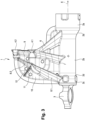
- the second connection port 4.2 is mechanically connected to the body 2 by a member 8 comprising two substantially rectilinear parts 8.1, 8.2 extending in the extension of one another from the external surface of the second end section 2c of the body 2 to a lower surface of the second connection port 4.2.
- the first part 8.1 of the member 8 connects the body 2 to the semicircular portion of the first duct 5.1 and has a V-shaped cross-section whose tip belongs to the plane A, such that said plane A substantially forms a plane of symmetry for the first part 8.1 of the member 8.
- the second part 8.2 of the member 8 connects the second connection port 4.2 to the semicircular portion of the first duct 5.1 and has a V-shaped cross-section whose tip belongs to the plane B, such that said plane B substantially forms a plane of symmetry for the second part 8.2 of the member 8.
- the free edges of the first part 8.1 of the member 8 substantially tangent the external surface of the second end section 2c of the body 2 and the free edges of the second part 8.2 of the member 8 substantially tangent to the external surface of the semicircular portion of the first conduit 5.1.
- the second connection port 4.2 is further mechanically connected to the body 2 and to the first connection port 4.1 by a substantially rectilinear member 9 extending from an upper surface of the first connection port 4.1 to a lower surface of the second connection port 4.2.
- the member 9 is substantially in the extension of the member 7 which forms a section common to the member 7 and to the member 9, and has a V-shaped cross-section whose tip belongs to the plane B, so that said plane B substantially forms a plane of symmetry for the member 9.
- the actuator 1 here comprises a veil 10 extending partly in the plane A and in the plane B, ensuring a connection between the supply conduits 5.1, 5.2, the members 6, 7, 8, 9 and the body 2.
- the web 10 is pierced with evacuation holes 11 making it possible to prevent a liquid from stagnating on said web 10 when the actuator is positioned in such a way that the web 10 is substantially horizontal.
- the actuator 1 also comprises a substantially rectilinear rib 12 extending on either side of the web 10 from the quarter-circle portion of the first conduit 5.1 to the junction between the semi-circle portion of the second conduit 5.2 and the second part 8.2 of the member 8.
- the rib 12 thus ensures a direct connection between the first conduit 5.1, the second conduit 5.2 and the member 8.
- the use of the members 6, 7, 8, 9 to connect the first connection port 4.1 and the second connection port 4.2 to the body 2 makes it possible to limit the weight of the actuator 1, the members leaving spaces between them devoid of material. It is also understood that the members are not sized for the transmission of the forces produced by the actuator but for the recovery of the vibratory forces, and the forces generated on the connection ports and the conduits by the fluid pressure, and the forces generated by the pipes on the connection ports.
- the actuator is obtained by additive manufacturing, in particular in a nickel and chromium alloy (such as that produced under the brand Inconel ® by the company Spécial Metals Corporation), in steel or in titanium.
- the veil 10 can then serve as a support for carry out a material deposit along the X axis and thus obtain a single-piece part.
- the V shape of the members makes it possible to limit the number of supports required for such a material deposit.
- the dimensioning of the actuator 1 for the vibration and pressure resistance of the connection ports and conduits 4.1, 4.2, 5.1, 5.2 is within the reach of those skilled in the art.
- the spacing of the members 6, 7, 8, 9 and their thickness will be defined in particular as a function of the desired moment of inertia.
- the actuator 1 is hydraulic and comprises connection ports 4.1, 4.2 and hydraulic conduits 5.1, 5.2, the actuator can also be electric and comprise connection ports and electrical conduits, or even pneumatic.
- the number of ports and supply lines can be equal to one (for example, a single-acting cylinder) or greater than two.
- the cross-section of the members has a V shape, it can be of different shapes (solid, hollow, I-shaped, etc.).
- the actuator may not include a sail 10.
- the veil 10 may be devoid of an evacuation hole 11.
- the body 2 is of generally tubular shape and comprises a succession of sections 2a, 2b, 2c, 2d having an external surface of cylindrical or truncated shape
- the body 2 may be of different shape and for example comprise only a single section having an external surface of cylindrical or other shape.
- the first connection port 4.1 and/or the second connection port 4.2 may not extend parallel to the central X-axis of the body 2.
- the actuator 1 is used to unlock the landing gear of an aircraft, the invention applies to any type of actuator requiring at least one remote connection port 4.1, 4.2, such as for example for opening and/or closing flaps closing the space in which the landing gear is housed, or for deploying thrust reversers.
- the actuator 1 can also be used in any field other than that of aeronautics.
Landscapes
- Engineering & Computer Science (AREA)
- Mechanical Engineering (AREA)
- Physics & Mathematics (AREA)
- Fluid Mechanics (AREA)
- General Engineering & Computer Science (AREA)
- Aviation & Aerospace Engineering (AREA)
- Actuator (AREA)
- Lock And Its Accessories (AREA)
Claims (13)
- Stellantrieb (1) mit einem sich entlang einer Mittelachse (X) erstreckenden Körper (2) und mit zumindest einem ersten, versetzten Verbindungsanschluss (4.1), der mit dem Körper (2) durch eine erste Leitung (5.1) verbunden ist, die sich über den Körper (2) hinaus vorstehend erstreckt, wobei der erste Verbindungsanschluss (4.1) durch zumindest einen ersten Spant (6) und einen zweiten Spant (7) mechanisch mit dem Körper verbunden ist, dadurch gekennzeichnet, dass sich der erste und der zweite Spant ausgehend von dem ersten Verbindungsanschluss bis hin zu jeweils einem ersten Körperabschnitt und einem axial von dem ersten Körperabschnitt entfernten, zweiten Körperabschnitt erstrecken.
- Stellantrieb (1) nach Anspruch 1, mit einem zweiten, versetzten Verbindungsanschluss (4.2), der durch eine zweite Leitung (5.2) mit dem Körper (2) verbunden ist, und wobei der zweite Verbindungsanschluss (4.2) durch zumindest einen dritten Spant (8) und einen vierten Spant (9) mechanisch mit dem Körper (2) verbunden ist, wobei sich der dritte und der vierte Spant ausgehend von dem zweiten Verbindungsanschluss bis hin zu zwei Körperabschnitten erstrecken, die axial voneinander entfernt sind.
- Stellantrieb nach Anspruch 2, wobei der zweite Verbindungsanschluss (4.2) mit dem ersten Verbindungsanschluss (4.1) fluchtet und wobei der vierte Spant (9) und der zweite Spant (7) einen gemeinsamen Abschnitt aufweisen.
- Stellantrieb nach Anspruch 2 oder 3, wobei der dritte Spant (8) und/oder der vierte Spant (9) derart angeordnet ist, dass er einen Teilabschnitt der ersten Leitung (5.1) mechanisch mit dem Körper (2) verbindet.
- Stellantrieb (1) nach einem der vorhergehenden Ansprüche, wobei zumindest zwei der Spanten (6, 7, 8, 9) einen Teilabschnitt aufweisen, der sich entlang einer Längsmittelebene (A) des Körpers (2) erstreckt.
- Stellantrieb (1) nach Anspruch 5, wobei sich die erste Leitung (5.1) entlang einer Längsmittelebene (A) des Körpers (2) erstreckt.
- Stellantrieb (1) nach einem der vorhergehenden Ansprüche, wobei der erste Spant (6) und der zweite Spant (7) eine etwa gleiche Länge aufweisen.
- Stellantrieb (1) nach einem der vorhergehenden Ansprüche, wobei zumindest einer der Spanten (6, 7, 8, 9) einen V-förmigen Querschnitt aufweist.
- Stellantrieb (1) nach einem der vorhergehenden Ansprüche, welcher ein Vlies (10) umfasst, das eine mechanische Verbindung zwischen dem Körper (2), jeder Leitung (5.1, 5.2) und den Spanten (6, 7, 8, 9) gewährleistet.
- Stellantrieb (1) nach Anspruch 9, wobei das Vlies (10) Auslassöffnungen (11) enthält.
- Stellantrieb (1) nach den Ansprüchen 9 oder 10, welcher zumindest eine Rippe (12) umfasst, die sich auf einer Seite des Vlieses (10) ausgehend von einer der Leitungen (5.2) bis hin zu einem der Spanten (8) erstreckt.
- Stellantrieb (1) nach einem der vorhergehenden Ansprüche, wobei der Körper (2), jede Leitung (5.1, 5.2) und jeder Verbindungsanschluss (4.1, 4.2) ein einstückiges Bauteil bilden, das durch additive Fertigung ausgebildet ist.
- Fahrwerk mit zumindest einer ausgefahrenen Position und einer eingezogenen Position und mit einem Stellantrieb für die Verriegelung oder die Entriegelung des Fahrwerks in zumindest einer der beiden Positionen, dadurch gekennzeichnet, dass der Stellantrieb einem der vorhergehenden Ansprüche entspricht.
Applications Claiming Priority (2)
| Application Number | Priority Date | Filing Date | Title |
|---|---|---|---|
| FR2000724A FR3106633B1 (fr) | 2020-01-24 | 2020-01-24 | Actionneur à port d’alimentation déporté |
| PCT/EP2021/051228 WO2021148486A1 (fr) | 2020-01-24 | 2021-01-20 | Actionneur a port d'alimentation deporte |
Publications (2)
| Publication Number | Publication Date |
|---|---|
| EP4093979A1 EP4093979A1 (de) | 2022-11-30 |
| EP4093979B1 true EP4093979B1 (de) | 2024-10-30 |
Family
ID=70154697
Family Applications (1)
| Application Number | Title | Priority Date | Filing Date |
|---|---|---|---|
| EP21700952.1A Active EP4093979B1 (de) | 2020-01-24 | 2021-01-20 | Stellantrieb mit versetztem versorgungsanschluss |
Country Status (5)
| Country | Link |
|---|---|
| US (1) | US12366257B2 (de) |
| EP (1) | EP4093979B1 (de) |
| CN (1) | CN115003920B (de) |
| FR (1) | FR3106633B1 (de) |
| WO (1) | WO2021148486A1 (de) |
Citations (3)
| Publication number | Priority date | Publication date | Assignee | Title |
|---|---|---|---|---|
| DE3820078A1 (de) * | 1987-06-16 | 1988-12-29 | Hoerbiger Hydraulik | Hydrozylinder |
| DE102011015648A1 (de) * | 2011-03-31 | 2012-10-04 | Festo Ag & Co. Kg | Fluidbetätigter Membranantrieb |
| DE102017206297A1 (de) * | 2017-04-12 | 2018-10-18 | Festo Ag & Co. Kg | Fluidbetätigter Arbeitszylinder und diesbezügliches Herstellungsverfahren |
Family Cites Families (15)
| Publication number | Priority date | Publication date | Assignee | Title |
|---|---|---|---|---|
| US1918426A (en) * | 1931-02-13 | 1933-07-18 | Jess C Radnor | Aircraft landing gear |
| US2336794A (en) * | 1939-12-21 | 1943-12-14 | Siam | Liftable undercarriage system for airplanes |
| US2401378A (en) * | 1943-03-13 | 1946-06-04 | Maytag Co | Hydraulic transfer tube for strut mechanism |
| US2475723A (en) * | 1945-02-05 | 1949-07-12 | Bendix Westinghouse Automotive | Fluid pressure control mechanism |
| FR1100745A (fr) * | 1953-05-19 | 1955-09-23 | British Messier Ltd | Perfectionnements aux vérins hydrauliques |
| US4948041A (en) * | 1988-01-20 | 1990-08-14 | Mccauley John P | Thermostatic garden hose protection device |
| DE19646827C1 (de) * | 1996-11-13 | 1998-01-15 | Mannesmann Sachs Ag | Anschluß für ein flüssiges oder gasförmiges Medium an der Außenwand eines Zylinders |
| FR2907097B1 (fr) * | 2006-10-17 | 2009-01-16 | Messier Bugatti Sa | Architecture de systeme hydraulique de manoeuvre d'atterrisseurs d'aeronef |
| DE102009021351A1 (de) * | 2008-06-05 | 2009-12-17 | Luk Lamellen Und Kupplungsbau Beteiligungs Kg | Nehmerzylinder |
| US8070095B2 (en) * | 2008-10-22 | 2011-12-06 | Goodrich Corporation | Shrinking shock strut system for retractable landing gear |
| GB2528966A (en) * | 2014-08-07 | 2016-02-10 | Airbus Operations Ltd | Landing gear drive system |
| DE102016217006B4 (de) * | 2016-09-07 | 2018-04-05 | Schaeffler Technologies AG & Co. KG | Kupplungsgeberzylinder mit zweigeteiltem Gehäuse |
| FR3074777B1 (fr) * | 2017-12-11 | 2024-01-05 | Safran Landing Systems | Procede de manœuvre d'un atterrisseur d'aeronef entre une position deployee et une position retractee |
| EP3505442B1 (de) * | 2017-12-28 | 2021-12-01 | Safran Landing Systems UK Ltd | Flugzeugbaugruppe |
| US20200191174A1 (en) * | 2018-12-13 | 2020-06-18 | Safran Landing Systems Canada Inc. | Multi-channel hydraulic snubbing device |
-
2020
- 2020-01-24 FR FR2000724A patent/FR3106633B1/fr active Active
-
2021
- 2021-01-20 US US17/794,209 patent/US12366257B2/en active Active
- 2021-01-20 EP EP21700952.1A patent/EP4093979B1/de active Active
- 2021-01-20 WO PCT/EP2021/051228 patent/WO2021148486A1/fr not_active Ceased
- 2021-01-20 CN CN202180010692.6A patent/CN115003920B/zh active Active
Patent Citations (3)
| Publication number | Priority date | Publication date | Assignee | Title |
|---|---|---|---|---|
| DE3820078A1 (de) * | 1987-06-16 | 1988-12-29 | Hoerbiger Hydraulik | Hydrozylinder |
| DE102011015648A1 (de) * | 2011-03-31 | 2012-10-04 | Festo Ag & Co. Kg | Fluidbetätigter Membranantrieb |
| DE102017206297A1 (de) * | 2017-04-12 | 2018-10-18 | Festo Ag & Co. Kg | Fluidbetätigter Arbeitszylinder und diesbezügliches Herstellungsverfahren |
Also Published As
| Publication number | Publication date |
|---|---|
| EP4093979A1 (de) | 2022-11-30 |
| US12366257B2 (en) | 2025-07-22 |
| WO2021148486A1 (fr) | 2021-07-29 |
| CN115003920B (zh) | 2025-08-26 |
| FR3106633A1 (fr) | 2021-07-30 |
| FR3106633B1 (fr) | 2022-02-04 |
| CN115003920A (zh) | 2022-09-02 |
| US20230045934A1 (en) | 2023-02-16 |
Similar Documents
| Publication | Publication Date | Title |
|---|---|---|
| EP0335786B1 (de) | Elastischer Streben mit integriertem, hydro-mechanischem Resonator, insbesondere für die Aufhängung eines Getriebes an einen Drehflügler und eine Aufhängevorrichtung mit einer solchen Verwendungsmöglichkeit | |
| EP2008933B1 (de) | Aufhängung eines Triebwerks an der Struktur eines Flugzeugs | |
| EP2410202B1 (de) | Vorrichtung zum Verbinden eines ersten Körpers mit einem zweiten Körper, insbesondere einsetzbar für die Befestigung eines Flugzeugtriebwerks | |
| BE1024622B1 (fr) | Vanne fluidique | |
| EP3996992B1 (de) | Fahrwerk mit verstärkungssteg | |
| EP3623647A1 (de) | Verbindungsvorrichtung mit zweifacher scherung, die mit einer exzentrischen achse und exzentrischen muffen ausgestattet ist, mechanische einheit, die eine solche vorrichtung umfasst, und zusammenbauverfahren | |
| EP2465772A1 (de) | Fluidischer Mikrogenerator von synthetischen Sprühstrahlen | |
| FR3099464A1 (fr) | Mat reacteur pour coupler un turboreacteur a une aile d’un aeronef | |
| EP3350420A1 (de) | Motorkurbelgehäusestützvorrichtung und schnittstelle | |
| EP3476740A1 (de) | Primärstruktur eines haltemasts einer luftfahrzeug-antriebsgruppe mit gehäuse, die aus zwei zusammengebauten halbschalen gebildet wird | |
| EP1050456A1 (de) | Verbindungsstruktur eines Flugzeugfahrwerkes zum Flugzeugrumpf | |
| EP4093979B1 (de) | Stellantrieb mit versetztem versorgungsanschluss | |
| CA2500494C (fr) | Longeron de fuselage pour aeronef et caisson central equipe d'un tel longeron | |
| FR3078950A1 (fr) | Structure primaire d'un mat de support d'un groupe propulseur d'aeronef dont la partie arriere est formee par un ensemble de bielles | |
| EP3728041B1 (de) | Öffnende triebwerksverkleidungsanordnung und einsatzmechanismus | |
| BE1026012B1 (fr) | Ensemble pour aeronef comprenant une surface portante mobile portée par un arbre d'actionnement traversant une fente equipée d'un joint d'etanchéité a efficacité de scellement améliorée | |
| EP3699092B1 (de) | Gruppe von teilen, die mittels einer durchgehenden welle montiert werden können, wenn die teile näherungsweise aneinandergereiht sind | |
| FR3061149A1 (fr) | Structure primaire d'un mat pour groupe propulseur d'aeronef comportant une partie pyramidale a montants convergents | |
| FR2999528A1 (fr) | Tube support de diaphragme en thermoplastique | |
| EP3728037B1 (de) | Tragende struktur zur montage auf einem gasgenerator | |
| EP3396196B1 (de) | Schwingungsfiltermechanismus zum einbau zwischen eine ausrüstung und einem rumpf eines luftfahrzeugs, und mit einem solchen mechanismus ausgestatteter sitz | |
| CA3146451C (fr) | Atterrisseur avec voile de renfort | |
| EP4574669A1 (de) | Montage eines befestigungsmastes mit einem flugzeugmotor | |
| EP2892806B1 (de) | Hilfsantriebsgetriebe zur steuerung der auftriebsklappen eines flugzeugs | |
| FR2916997A1 (fr) | Dispositif de prehension pour robot de montage |
Legal Events
| Date | Code | Title | Description |
|---|---|---|---|
| STAA | Information on the status of an ep patent application or granted ep patent |
Free format text: STATUS: UNKNOWN |
|
| STAA | Information on the status of an ep patent application or granted ep patent |
Free format text: STATUS: THE INTERNATIONAL PUBLICATION HAS BEEN MADE |
|
| PUAI | Public reference made under article 153(3) epc to a published international application that has entered the european phase |
Free format text: ORIGINAL CODE: 0009012 |
|
| STAA | Information on the status of an ep patent application or granted ep patent |
Free format text: STATUS: REQUEST FOR EXAMINATION WAS MADE |
|
| 17P | Request for examination filed |
Effective date: 20220727 |
|
| AK | Designated contracting states |
Kind code of ref document: A1 Designated state(s): AL AT BE BG CH CY CZ DE DK EE ES FI FR GB GR HR HU IE IS IT LI LT LU LV MC MK MT NL NO PL PT RO RS SE SI SK SM TR |
|
| DAV | Request for validation of the european patent (deleted) | ||
| DAX | Request for extension of the european patent (deleted) | ||
| STAA | Information on the status of an ep patent application or granted ep patent |
Free format text: STATUS: EXAMINATION IS IN PROGRESS |
|
| 17Q | First examination report despatched |
Effective date: 20231204 |
|
| GRAP | Despatch of communication of intention to grant a patent |
Free format text: ORIGINAL CODE: EPIDOSNIGR1 |
|
| STAA | Information on the status of an ep patent application or granted ep patent |
Free format text: STATUS: GRANT OF PATENT IS INTENDED |
|
| INTG | Intention to grant announced |
Effective date: 20240531 |
|
| GRAS | Grant fee paid |
Free format text: ORIGINAL CODE: EPIDOSNIGR3 |
|
| GRAA | (expected) grant |
Free format text: ORIGINAL CODE: 0009210 |
|
| STAA | Information on the status of an ep patent application or granted ep patent |
Free format text: STATUS: THE PATENT HAS BEEN GRANTED |
|
| AK | Designated contracting states |
Kind code of ref document: B1 Designated state(s): AL AT BE BG CH CY CZ DE DK EE ES FI FR GB GR HR HU IE IS IT LI LT LU LV MC MK MT NL NO PL PT RO RS SE SI SK SM TR |
|
| REG | Reference to a national code |
Ref country code: GB Ref legal event code: FG4D Free format text: NOT ENGLISH |
|
| REG | Reference to a national code |
Ref country code: CH Ref legal event code: EP |
|
| REG | Reference to a national code |
Ref country code: IE Ref legal event code: FG4D Free format text: LANGUAGE OF EP DOCUMENT: FRENCH |
|
| REG | Reference to a national code |
Ref country code: DE Ref legal event code: R096 Ref document number: 602021020976 Country of ref document: DE |
|
| REG | Reference to a national code |
Ref country code: LT Ref legal event code: MG9D |
|
| REG | Reference to a national code |
Ref country code: NL Ref legal event code: MP Effective date: 20241030 |
|
| PG25 | Lapsed in a contracting state [announced via postgrant information from national office to epo] |
Ref country code: IS Free format text: LAPSE BECAUSE OF FAILURE TO SUBMIT A TRANSLATION OF THE DESCRIPTION OR TO PAY THE FEE WITHIN THE PRESCRIBED TIME-LIMIT Effective date: 20250228 Ref country code: HR Free format text: LAPSE BECAUSE OF FAILURE TO SUBMIT A TRANSLATION OF THE DESCRIPTION OR TO PAY THE FEE WITHIN THE PRESCRIBED TIME-LIMIT Effective date: 20241030 Ref country code: PT Free format text: LAPSE BECAUSE OF FAILURE TO SUBMIT A TRANSLATION OF THE DESCRIPTION OR TO PAY THE FEE WITHIN THE PRESCRIBED TIME-LIMIT Effective date: 20250228 |
|
| PG25 | Lapsed in a contracting state [announced via postgrant information from national office to epo] |
Ref country code: FI Free format text: LAPSE BECAUSE OF FAILURE TO SUBMIT A TRANSLATION OF THE DESCRIPTION OR TO PAY THE FEE WITHIN THE PRESCRIBED TIME-LIMIT Effective date: 20241030 Ref country code: NL Free format text: LAPSE BECAUSE OF FAILURE TO SUBMIT A TRANSLATION OF THE DESCRIPTION OR TO PAY THE FEE WITHIN THE PRESCRIBED TIME-LIMIT Effective date: 20241030 |
|
| REG | Reference to a national code |
Ref country code: AT Ref legal event code: MK05 Ref document number: 1737119 Country of ref document: AT Kind code of ref document: T Effective date: 20241030 |
|
| PG25 | Lapsed in a contracting state [announced via postgrant information from national office to epo] |
Ref country code: BG Free format text: LAPSE BECAUSE OF FAILURE TO SUBMIT A TRANSLATION OF THE DESCRIPTION OR TO PAY THE FEE WITHIN THE PRESCRIBED TIME-LIMIT Effective date: 20241030 |
|
| PG25 | Lapsed in a contracting state [announced via postgrant information from national office to epo] |
Ref country code: ES Free format text: LAPSE BECAUSE OF FAILURE TO SUBMIT A TRANSLATION OF THE DESCRIPTION OR TO PAY THE FEE WITHIN THE PRESCRIBED TIME-LIMIT Effective date: 20241030 |
|
| PG25 | Lapsed in a contracting state [announced via postgrant information from national office to epo] |
Ref country code: NO Free format text: LAPSE BECAUSE OF FAILURE TO SUBMIT A TRANSLATION OF THE DESCRIPTION OR TO PAY THE FEE WITHIN THE PRESCRIBED TIME-LIMIT Effective date: 20250130 |
|
| PG25 | Lapsed in a contracting state [announced via postgrant information from national office to epo] |
Ref country code: LV Free format text: LAPSE BECAUSE OF FAILURE TO SUBMIT A TRANSLATION OF THE DESCRIPTION OR TO PAY THE FEE WITHIN THE PRESCRIBED TIME-LIMIT Effective date: 20241030 Ref country code: GR Free format text: LAPSE BECAUSE OF FAILURE TO SUBMIT A TRANSLATION OF THE DESCRIPTION OR TO PAY THE FEE WITHIN THE PRESCRIBED TIME-LIMIT Effective date: 20250131 Ref country code: AT Free format text: LAPSE BECAUSE OF FAILURE TO SUBMIT A TRANSLATION OF THE DESCRIPTION OR TO PAY THE FEE WITHIN THE PRESCRIBED TIME-LIMIT Effective date: 20241030 |
|
| PG25 | Lapsed in a contracting state [announced via postgrant information from national office to epo] |
Ref country code: PL Free format text: LAPSE BECAUSE OF FAILURE TO SUBMIT A TRANSLATION OF THE DESCRIPTION OR TO PAY THE FEE WITHIN THE PRESCRIBED TIME-LIMIT Effective date: 20241030 |
|
| PG25 | Lapsed in a contracting state [announced via postgrant information from national office to epo] |
Ref country code: RS Free format text: LAPSE BECAUSE OF FAILURE TO SUBMIT A TRANSLATION OF THE DESCRIPTION OR TO PAY THE FEE WITHIN THE PRESCRIBED TIME-LIMIT Effective date: 20250130 |
|
| PG25 | Lapsed in a contracting state [announced via postgrant information from national office to epo] |
Ref country code: SM Free format text: LAPSE BECAUSE OF FAILURE TO SUBMIT A TRANSLATION OF THE DESCRIPTION OR TO PAY THE FEE WITHIN THE PRESCRIBED TIME-LIMIT Effective date: 20241030 |
|
| PG25 | Lapsed in a contracting state [announced via postgrant information from national office to epo] |
Ref country code: DK Free format text: LAPSE BECAUSE OF FAILURE TO SUBMIT A TRANSLATION OF THE DESCRIPTION OR TO PAY THE FEE WITHIN THE PRESCRIBED TIME-LIMIT Effective date: 20241030 |
|
| PG25 | Lapsed in a contracting state [announced via postgrant information from national office to epo] |
Ref country code: EE Free format text: LAPSE BECAUSE OF FAILURE TO SUBMIT A TRANSLATION OF THE DESCRIPTION OR TO PAY THE FEE WITHIN THE PRESCRIBED TIME-LIMIT Effective date: 20241030 |
|
| PG25 | Lapsed in a contracting state [announced via postgrant information from national office to epo] |
Ref country code: RO Free format text: LAPSE BECAUSE OF FAILURE TO SUBMIT A TRANSLATION OF THE DESCRIPTION OR TO PAY THE FEE WITHIN THE PRESCRIBED TIME-LIMIT Effective date: 20241030 |
|
| PG25 | Lapsed in a contracting state [announced via postgrant information from national office to epo] |
Ref country code: SK Free format text: LAPSE BECAUSE OF FAILURE TO SUBMIT A TRANSLATION OF THE DESCRIPTION OR TO PAY THE FEE WITHIN THE PRESCRIBED TIME-LIMIT Effective date: 20241030 |
|
| PG25 | Lapsed in a contracting state [announced via postgrant information from national office to epo] |
Ref country code: CZ Free format text: LAPSE BECAUSE OF FAILURE TO SUBMIT A TRANSLATION OF THE DESCRIPTION OR TO PAY THE FEE WITHIN THE PRESCRIBED TIME-LIMIT Effective date: 20241030 |
|
| PG25 | Lapsed in a contracting state [announced via postgrant information from national office to epo] |
Ref country code: IT Free format text: LAPSE BECAUSE OF FAILURE TO SUBMIT A TRANSLATION OF THE DESCRIPTION OR TO PAY THE FEE WITHIN THE PRESCRIBED TIME-LIMIT Effective date: 20241030 |
|
| REG | Reference to a national code |
Ref country code: DE Ref legal event code: R097 Ref document number: 602021020976 Country of ref document: DE |
|
| REG | Reference to a national code |
Ref country code: CH Ref legal event code: PL |
|
| PLBE | No opposition filed within time limit |
Free format text: ORIGINAL CODE: 0009261 |
|
| STAA | Information on the status of an ep patent application or granted ep patent |
Free format text: STATUS: NO OPPOSITION FILED WITHIN TIME LIMIT |
|
| PG25 | Lapsed in a contracting state [announced via postgrant information from national office to epo] |
Ref country code: SE Free format text: LAPSE BECAUSE OF FAILURE TO SUBMIT A TRANSLATION OF THE DESCRIPTION OR TO PAY THE FEE WITHIN THE PRESCRIBED TIME-LIMIT Effective date: 20241030 |
|
| PG25 | Lapsed in a contracting state [announced via postgrant information from national office to epo] |
Ref country code: MC Free format text: LAPSE BECAUSE OF FAILURE TO SUBMIT A TRANSLATION OF THE DESCRIPTION OR TO PAY THE FEE WITHIN THE PRESCRIBED TIME-LIMIT Effective date: 20241030 Ref country code: LU Free format text: LAPSE BECAUSE OF NON-PAYMENT OF DUE FEES Effective date: 20250120 |
|
| 26N | No opposition filed |
Effective date: 20250731 |
|
| PG25 | Lapsed in a contracting state [announced via postgrant information from national office to epo] |
Ref country code: BE Free format text: LAPSE BECAUSE OF NON-PAYMENT OF DUE FEES Effective date: 20250131 |
|
| PG25 | Lapsed in a contracting state [announced via postgrant information from national office to epo] |
Ref country code: CH Free format text: LAPSE BECAUSE OF NON-PAYMENT OF DUE FEES Effective date: 20250131 |
|
| REG | Reference to a national code |
Ref country code: BE Ref legal event code: MM Effective date: 20250131 |
|
| PG25 | Lapsed in a contracting state [announced via postgrant information from national office to epo] |
Ref country code: IE Free format text: LAPSE BECAUSE OF NON-PAYMENT OF DUE FEES Effective date: 20250120 |
|
| PGFP | Annual fee paid to national office [announced via postgrant information from national office to epo] |
Ref country code: GB Payment date: 20260122 Year of fee payment: 6 |
|
| PGFP | Annual fee paid to national office [announced via postgrant information from national office to epo] |
Ref country code: DE Payment date: 20260120 Year of fee payment: 6 |
|
| PGFP | Annual fee paid to national office [announced via postgrant information from national office to epo] |
Ref country code: FR Payment date: 20260116 Year of fee payment: 6 |