EP4093169A1 - Heat exchanger for power electronics - Google Patents
Heat exchanger for power electronics Download PDFInfo
- Publication number
- EP4093169A1 EP4093169A1 EP22174616.7A EP22174616A EP4093169A1 EP 4093169 A1 EP4093169 A1 EP 4093169A1 EP 22174616 A EP22174616 A EP 22174616A EP 4093169 A1 EP4093169 A1 EP 4093169A1
- Authority
- EP
- European Patent Office
- Prior art keywords
- heat exchanger
- hydraulic diameter
- flow
- flow constriction
- fluid
- Prior art date
- Legal status (The legal status is an assumption and is not a legal conclusion. Google has not performed a legal analysis and makes no representation as to the accuracy of the status listed.)
- Granted
Links
Images




Classifications
-
- H—ELECTRICITY
- H05—ELECTRIC TECHNIQUES NOT OTHERWISE PROVIDED FOR
- H05K—PRINTED CIRCUITS; CASINGS OR CONSTRUCTIONAL DETAILS OF ELECTRIC APPARATUS; MANUFACTURE OF ASSEMBLAGES OF ELECTRICAL COMPONENTS
- H05K7/00—Constructional details common to different types of electric apparatus
- H05K7/20—Modifications to facilitate cooling, ventilating, or heating
- H05K7/2029—Modifications to facilitate cooling, ventilating, or heating using a liquid coolant with phase change in electronic enclosures
- H05K7/20309—Evaporators
-
- F—MECHANICAL ENGINEERING; LIGHTING; HEATING; WEAPONS; BLASTING
- F25—REFRIGERATION OR COOLING; COMBINED HEATING AND REFRIGERATION SYSTEMS; HEAT PUMP SYSTEMS; MANUFACTURE OR STORAGE OF ICE; LIQUEFACTION SOLIDIFICATION OF GASES
- F25B—REFRIGERATION MACHINES, PLANTS OR SYSTEMS; COMBINED HEATING AND REFRIGERATION SYSTEMS; HEAT PUMP SYSTEMS
- F25B39/00—Evaporators; Condensers
-
- F—MECHANICAL ENGINEERING; LIGHTING; HEATING; WEAPONS; BLASTING
- F25—REFRIGERATION OR COOLING; COMBINED HEATING AND REFRIGERATION SYSTEMS; HEAT PUMP SYSTEMS; MANUFACTURE OR STORAGE OF ICE; LIQUEFACTION SOLIDIFICATION OF GASES
- F25B—REFRIGERATION MACHINES, PLANTS OR SYSTEMS; COMBINED HEATING AND REFRIGERATION SYSTEMS; HEAT PUMP SYSTEMS
- F25B1/00—Compression machines, plants or systems with non-reversible cycle
-
- F—MECHANICAL ENGINEERING; LIGHTING; HEATING; WEAPONS; BLASTING
- F25—REFRIGERATION OR COOLING; COMBINED HEATING AND REFRIGERATION SYSTEMS; HEAT PUMP SYSTEMS; MANUFACTURE OR STORAGE OF ICE; LIQUEFACTION SOLIDIFICATION OF GASES
- F25B—REFRIGERATION MACHINES, PLANTS OR SYSTEMS; COMBINED HEATING AND REFRIGERATION SYSTEMS; HEAT PUMP SYSTEMS
- F25B39/00—Evaporators; Condensers
- F25B39/02—Evaporators
-
- F—MECHANICAL ENGINEERING; LIGHTING; HEATING; WEAPONS; BLASTING
- F25—REFRIGERATION OR COOLING; COMBINED HEATING AND REFRIGERATION SYSTEMS; HEAT PUMP SYSTEMS; MANUFACTURE OR STORAGE OF ICE; LIQUEFACTION SOLIDIFICATION OF GASES
- F25B—REFRIGERATION MACHINES, PLANTS OR SYSTEMS; COMBINED HEATING AND REFRIGERATION SYSTEMS; HEAT PUMP SYSTEMS
- F25B5/00—Compression machines, plants or systems, with several evaporator circuits, e.g. for varying refrigerating capacity
- F25B5/02—Compression machines, plants or systems, with several evaporator circuits, e.g. for varying refrigerating capacity arranged in parallel
-
- F—MECHANICAL ENGINEERING; LIGHTING; HEATING; WEAPONS; BLASTING
- F28—HEAT EXCHANGE IN GENERAL
- F28F—DETAILS OF HEAT-EXCHANGE AND HEAT-TRANSFER APPARATUS, OF GENERAL APPLICATION
- F28F3/00—Plate-like or laminated elements; Assemblies of plate-like or laminated elements
- F28F3/12—Elements constructed in the shape of a hollow panel, e.g. with channels
-
- H—ELECTRICITY
- H05—ELECTRIC TECHNIQUES NOT OTHERWISE PROVIDED FOR
- H05K—PRINTED CIRCUITS; CASINGS OR CONSTRUCTIONAL DETAILS OF ELECTRIC APPARATUS; MANUFACTURE OF ASSEMBLAGES OF ELECTRICAL COMPONENTS
- H05K7/00—Constructional details common to different types of electric apparatus
- H05K7/20—Modifications to facilitate cooling, ventilating, or heating
- H05K7/20218—Modifications to facilitate cooling, ventilating, or heating using a liquid coolant without phase change in electronic enclosures
- H05K7/20263—Heat dissipaters releasing heat from coolant
-
- H—ELECTRICITY
- H05—ELECTRIC TECHNIQUES NOT OTHERWISE PROVIDED FOR
- H05K—PRINTED CIRCUITS; CASINGS OR CONSTRUCTIONAL DETAILS OF ELECTRIC APPARATUS; MANUFACTURE OF ASSEMBLAGES OF ELECTRICAL COMPONENTS
- H05K7/00—Constructional details common to different types of electric apparatus
- H05K7/20—Modifications to facilitate cooling, ventilating, or heating
- H05K7/20218—Modifications to facilitate cooling, ventilating, or heating using a liquid coolant without phase change in electronic enclosures
- H05K7/20272—Accessories for moving fluid, for expanding fluid, for connecting fluid conduits, for distributing fluid, for removing gas or for preventing leakage, e.g. pumps, tanks or manifolds
-
- H—ELECTRICITY
- H05—ELECTRIC TECHNIQUES NOT OTHERWISE PROVIDED FOR
- H05K—PRINTED CIRCUITS; CASINGS OR CONSTRUCTIONAL DETAILS OF ELECTRIC APPARATUS; MANUFACTURE OF ASSEMBLAGES OF ELECTRICAL COMPONENTS
- H05K7/00—Constructional details common to different types of electric apparatus
- H05K7/20—Modifications to facilitate cooling, ventilating, or heating
- H05K7/2029—Modifications to facilitate cooling, ventilating, or heating using a liquid coolant with phase change in electronic enclosures
- H05K7/203—Modifications to facilitate cooling, ventilating, or heating using a liquid coolant with phase change in electronic enclosures by immersion
-
- H—ELECTRICITY
- H05—ELECTRIC TECHNIQUES NOT OTHERWISE PROVIDED FOR
- H05K—PRINTED CIRCUITS; CASINGS OR CONSTRUCTIONAL DETAILS OF ELECTRIC APPARATUS; MANUFACTURE OF ASSEMBLAGES OF ELECTRICAL COMPONENTS
- H05K7/00—Constructional details common to different types of electric apparatus
- H05K7/20—Modifications to facilitate cooling, ventilating, or heating
- H05K7/2029—Modifications to facilitate cooling, ventilating, or heating using a liquid coolant with phase change in electronic enclosures
- H05K7/20354—Refrigerating circuit comprising a compressor
-
- H—ELECTRICITY
- H05—ELECTRIC TECHNIQUES NOT OTHERWISE PROVIDED FOR
- H05K—PRINTED CIRCUITS; CASINGS OR CONSTRUCTIONAL DETAILS OF ELECTRIC APPARATUS; MANUFACTURE OF ASSEMBLAGES OF ELECTRICAL COMPONENTS
- H05K7/00—Constructional details common to different types of electric apparatus
- H05K7/20—Modifications to facilitate cooling, ventilating, or heating
- H05K7/2089—Modifications to facilitate cooling, ventilating, or heating for power electronics, e.g. for inverters for controlling motor
- H05K7/20927—Liquid coolant without phase change
-
- H—ELECTRICITY
- H05—ELECTRIC TECHNIQUES NOT OTHERWISE PROVIDED FOR
- H05K—PRINTED CIRCUITS; CASINGS OR CONSTRUCTIONAL DETAILS OF ELECTRIC APPARATUS; MANUFACTURE OF ASSEMBLAGES OF ELECTRICAL COMPONENTS
- H05K7/00—Constructional details common to different types of electric apparatus
- H05K7/20—Modifications to facilitate cooling, ventilating, or heating
- H05K7/2089—Modifications to facilitate cooling, ventilating, or heating for power electronics, e.g. for inverters for controlling motor
- H05K7/20936—Liquid coolant with phase change
-
- H—ELECTRICITY
- H10—SEMICONDUCTOR DEVICES; ELECTRIC SOLID-STATE DEVICES NOT OTHERWISE PROVIDED FOR
- H10W—GENERIC PACKAGES, INTERCONNECTIONS, CONNECTORS OR OTHER CONSTRUCTIONAL DETAILS OF DEVICES COVERED BY CLASS H10
- H10W40/00—Arrangements for thermal protection or thermal control
- H10W40/70—Fillings or auxiliary members in containers or in encapsulations for thermal protection or control
- H10W40/73—Fillings or auxiliary members in containers or in encapsulations for thermal protection or control for cooling by change of state
-
- F—MECHANICAL ENGINEERING; LIGHTING; HEATING; WEAPONS; BLASTING
- F25—REFRIGERATION OR COOLING; COMBINED HEATING AND REFRIGERATION SYSTEMS; HEAT PUMP SYSTEMS; MANUFACTURE OR STORAGE OF ICE; LIQUEFACTION SOLIDIFICATION OF GASES
- F25B—REFRIGERATION MACHINES, PLANTS OR SYSTEMS; COMBINED HEATING AND REFRIGERATION SYSTEMS; HEAT PUMP SYSTEMS
- F25B2400/00—Component parts or details not otherwise provided for in this subclass
- F25B2400/04—Refrigeration circuit bypassing means
- F25B2400/0411—Refrigeration circuit bypassing means for expansion valves or capillary tubes
-
- F—MECHANICAL ENGINEERING; LIGHTING; HEATING; WEAPONS; BLASTING
- F25—REFRIGERATION OR COOLING; COMBINED HEATING AND REFRIGERATION SYSTEMS; HEAT PUMP SYSTEMS; MANUFACTURE OR STORAGE OF ICE; LIQUEFACTION SOLIDIFICATION OF GASES
- F25B—REFRIGERATION MACHINES, PLANTS OR SYSTEMS; COMBINED HEATING AND REFRIGERATION SYSTEMS; HEAT PUMP SYSTEMS
- F25B39/00—Evaporators; Condensers
- F25B39/02—Evaporators
- F25B39/022—Evaporators with plate-like or laminated elements
- F25B39/024—Evaporators with plate-like or laminated elements with elements constructed in the shape of a hollow panel
-
- F—MECHANICAL ENGINEERING; LIGHTING; HEATING; WEAPONS; BLASTING
- F28—HEAT EXCHANGE IN GENERAL
- F28D—HEAT-EXCHANGE APPARATUS, NOT PROVIDED FOR IN ANOTHER SUBCLASS, IN WHICH THE HEAT-EXCHANGE MEDIA DO NOT COME INTO DIRECT CONTACT
- F28D15/00—Heat-exchange apparatus with the intermediate heat-transfer medium in closed tubes passing into or through the conduit walls ; Heat-exchange apparatus employing intermediate heat-transfer medium or bodies
- F28D15/02—Heat-exchange apparatus with the intermediate heat-transfer medium in closed tubes passing into or through the conduit walls ; Heat-exchange apparatus employing intermediate heat-transfer medium or bodies in which the medium condenses and evaporates, e.g. heat pipes
- F28D15/0266—Heat-exchange apparatus with the intermediate heat-transfer medium in closed tubes passing into or through the conduit walls ; Heat-exchange apparatus employing intermediate heat-transfer medium or bodies in which the medium condenses and evaporates, e.g. heat pipes with separate evaporating and condensing chambers connected by at least one conduit; Loop-type heat pipes; with multiple or common evaporating or condensing chambers
-
- F—MECHANICAL ENGINEERING; LIGHTING; HEATING; WEAPONS; BLASTING
- F28—HEAT EXCHANGE IN GENERAL
- F28D—HEAT-EXCHANGE APPARATUS, NOT PROVIDED FOR IN ANOTHER SUBCLASS, IN WHICH THE HEAT-EXCHANGE MEDIA DO NOT COME INTO DIRECT CONTACT
- F28D15/00—Heat-exchange apparatus with the intermediate heat-transfer medium in closed tubes passing into or through the conduit walls ; Heat-exchange apparatus employing intermediate heat-transfer medium or bodies
- F28D15/02—Heat-exchange apparatus with the intermediate heat-transfer medium in closed tubes passing into or through the conduit walls ; Heat-exchange apparatus employing intermediate heat-transfer medium or bodies in which the medium condenses and evaporates, e.g. heat pipes
- F28D2015/0216—Heat-exchange apparatus with the intermediate heat-transfer medium in closed tubes passing into or through the conduit walls ; Heat-exchange apparatus employing intermediate heat-transfer medium or bodies in which the medium condenses and evaporates, e.g. heat pipes having particular orientation, e.g. slanted, or being orientation-independent
-
- F—MECHANICAL ENGINEERING; LIGHTING; HEATING; WEAPONS; BLASTING
- F28—HEAT EXCHANGE IN GENERAL
- F28D—HEAT-EXCHANGE APPARATUS, NOT PROVIDED FOR IN ANOTHER SUBCLASS, IN WHICH THE HEAT-EXCHANGE MEDIA DO NOT COME INTO DIRECT CONTACT
- F28D21/00—Heat-exchange apparatus not covered by any of the groups F28D1/00 - F28D20/00
- F28D2021/0019—Other heat exchangers for particular applications; Heat exchange systems not otherwise provided for
- F28D2021/0028—Other heat exchangers for particular applications; Heat exchange systems not otherwise provided for for cooling heat generating elements, e.g. for cooling electronic components or electric devices
- F28D2021/0029—Heat sinks
-
- F—MECHANICAL ENGINEERING; LIGHTING; HEATING; WEAPONS; BLASTING
- F28—HEAT EXCHANGE IN GENERAL
- F28D—HEAT-EXCHANGE APPARATUS, NOT PROVIDED FOR IN ANOTHER SUBCLASS, IN WHICH THE HEAT-EXCHANGE MEDIA DO NOT COME INTO DIRECT CONTACT
- F28D21/00—Heat-exchange apparatus not covered by any of the groups F28D1/00 - F28D20/00
- F28D2021/0019—Other heat exchangers for particular applications; Heat exchange systems not otherwise provided for
- F28D2021/0068—Other heat exchangers for particular applications; Heat exchange systems not otherwise provided for for refrigerant cycles
- F28D2021/0071—Evaporators
Definitions
- the third flow constriction hydraulic diameter is equal to from 1.2 to 1.5 times the second flow constriction hydraulic diameter.
- the expansion valve bypass circuit comprises two electronics coolers disposed in parallel flow arrangement, one for cooling a power rectifier and the other for cooling an inverter.
- the fluid circuit formed between the plates can be fluidly connected to the fluid inlet 10 and the fluid outlet 30 and include an inlet manifold 12, an outlet manifold 28, and a plurality of fluid passages 20 extending between and fluidly connecting the inlet manifold 12 and outlet manifold 28.
- the inlet manifold 12 and outlet manifold 28 can be arranged in any shape sufficient to deliver fluid from the fluid inlet 10 to the fluid passages 20.
- the inlet manifold 12, the outlet manifold 28, or both can include a major axis 13 which extends perpendicular to the fluid passages 20.
- the flow characteristics of the two flowpaths (50a, 50b) of the first group 25a can be substantially equal, e.g., due to having substantially equal ratios of flow constriction hydraulic diameter to fluid passage hydraulic diameter, the fluid passages (20a, 20b) and flow constrictions (22a, 22b) of the group 25a having substantially similar geometric construction (e.g., shape, dimensions, and the like), a combination thereof, or the like.
- the length of the fluid passages 20, divided by the hydraulic diameter of the fluid passage 20 can be from about 25 to about 250, or from about 30 to about 200, or from about 40 to about 180, or from about 50 to about 150, or from about 60 to about 140, or from about 75 to about 130, or from about 90 to about 120, or from about 100 to about 120, or from about 105 to about 115, or about 110, or about 111, or about 112.
Landscapes
- Engineering & Computer Science (AREA)
- Microelectronics & Electronic Packaging (AREA)
- Physics & Mathematics (AREA)
- Thermal Sciences (AREA)
- Mechanical Engineering (AREA)
- General Engineering & Computer Science (AREA)
- Heat-Exchange Devices With Radiators And Conduit Assemblies (AREA)
Abstract
Description
- The invention pertains to the art of heat exchangers. More particularly, the present invention relates to configurations of heat exchangers for cooling power electronics.
- Power electronic devices such as motor drives can generate waste heat during operation based on the efficiency of the device. Additionally, when the power electronic devices heat up their efficiency can degrade adding to the amount of heat they generate. When configured into a refrigeration system, effective thermal integration of these devices can be important aspect to the system's overall efficiency and reliability. Consequently, a goal of the system integrator is to maintain these components within a range of operating temperatures which will maximize the system efficiency. Accordingly, there remains a need in the art for heat exchangers configured to closely integrate with power electronic devices which can maintain optimal temperatures for these components under a variety of load conditions.
- According to a first aspect of the present invention there is provided a heat exchanger comprising a pair of metal plates joined along corresponding mating surfaces, wherein at least one of the metal plates comprises a plurality of connected recesses which form a fluid circuit between the plates when the plates are joined, wherein the fluid circuit comprises an inlet, an inlet manifold, an outlet, an outlet manifold, and a plurality of flowpaths extending between and fluidly connecting the inlet manifold and outlet manifold, wherein one or more of the plurality of flowpaths comprise a fluid passage and a flow constriction, and wherein a ratio of the hydraulic diameter of the flow constriction to the hydraulic diameter of the fluid passage increases with increasing distance from the inlet.
- Optionally, the heat exchanger is configured for operation in a substantially vertical orientation, wherein a major axis of the inlet manifold and a major axis of the outlet manifold extend substantially vertically, and the plurality of fluid passages are arranged one atop of the other, and wherein the inlet is disposed below the outlet such that during operation a flow direction of a refrigerant through the inlet and outlet manifolds opposes gravity.
- Optionally, a first flow constriction is disposed in the fluid passage closest to the inlet and comprises a ratio of hydraulic diameter of the flow constriction to the hydraulic diameter of the fluid passage of between 0.3 and 0.5 inclusive or end points.
- Optionally, the flow constrictions are disposed between the fluid passages and the inlet manifold.
- Optionally, both plates comprise correspondingly arranged connected recess that when joined form the fluid circuit.
- Optionally, a first group of two or more adjacent flowpaths closest to the inlet comprise a flow constriction having a first flow constriction hydraulic diameter and a second group of two or more adjacent flowpaths, not in the first group, comprise a flow constriction having a second flow constriction hydraulic diameter, and wherein the second flow constriction hydraulic diameter is greater than the first flow constriction hydraulic diameter.
- Optionally, the second flow constriction hydraulic diameter is equal to from 1.2 to 1.5 times the first flow constriction hydraulic diameter.
- Optionally, the heat exchanger further comprises a third group of two or more adjacent flowpaths, not in the first group or second group, comprising a flow constriction having a third flow constriction hydraulic diameter, and wherein the third flow constriction hydraulic diameter is greater than each the first flow constriction hydraulic diameter and the second flow constriction hydraulic diameter.
- Optionally, the third flow constriction hydraulic diameter is equal to from 1.2 to 1.5 times the second flow constriction hydraulic diameter.
- Optionally, the second flow constriction hydraulic diameter is equal to from 1.2 to 1.5 times the first flow constriction hydraulic diameter and the third flow constriction hydraulic diameter is equal to between 1.2 and 1.5 times the second flow constriction hydraulic diameter.
- Optionally, the heat exchanger comprises greater than two groups of adjacent flowpaths through the heat exchanger, each flowpath comprising a fluid passage and a flow constriction, wherein the flow constrictions in flowpaths of groups further distanced from the inlet comprises a flow constriction hydraulic diameter equal to from 1.2 to 1.5 times the flow constriction hydraulic diameter of the flow constrictions in the flowpaths of groups immediately adjacent and closer to the inlet.
- Optionally, during operation, the refrigerant entering the inlet is a single phase liquid refrigerant has a vapor quality equal to zero, and the refrigerant exiting the outlet is a two-phase mixture has a vapor quality between 0.4 and 0.6, inclusive of end points.
- Optionally, the heat exchanger further comprises a power electronics module mounting feature disposed on a face of one of the metal plates, and wherein the face is disposed on a side of the metal plate opposite the mating surface.
- Optionally, the connected recesses forming the inlet and outlet each comprise an engagement feature for securing a fluid conduit thereto.
- Optionally, the plates are joined by a weld and wherein the weld forms a seal between the plates along at least a portion of the mating surfaces.
- Optionally, the plates are joined by a compression mechanism configured to hold the plates together.
- Optionally, the heat exchanger further comprises a seal material disposed between the plates for preventing leakage from the fluid circuit.
- Optionally, the fluid passage extends at a tilt angle of less than or equal to 10°.
- According to a second aspect of the present invention there is provided a refrigerant cycle machine comprising a primary refrigeration circuit configured for passing a refrigerant through a compressor, a heat rejecting heat exchanger, an expansion valve, and a heat absorbing heat exchanger in a serial flow arrangement, an expansion valve bypass circuit for diverting at least a portion of the refrigerant exiting the condenser of the primary refrigeration circuit to an electronics cooler and returning the portion of the refrigerant to the evaporator, and wherein the electronics cooler comprises the heat exchanger as described herein with reference to the first aspect of the invention and wherein the portion of the refrigerant is directed through the heat exchanger to cool one or more power electronics modules attached in thermal communication thereto.
- Optionally, the expansion valve bypass circuit comprises two electronics coolers disposed in parallel flow arrangement, one for cooling a power rectifier and the other for cooling an inverter.
- The foregoing features and elements may be combined in various combinations without exclusivity, unless expressly indicated otherwise. These features and elements as well as the operation thereof will become more apparent in light of the following description and the accompanying drawings. It should be understood, however, that the following description and drawings are intended to be illustrative and explanatory in nature and non-limiting.
- The following descriptions should not be considered limiting in any way and are provided by way of example only. With reference to the accompanying drawings, like elements are numbered alike:
-
FIG. 1 is a schematic illustration of a heat exchanger having and power electronic modules mounted thereto in an example embodiment. -
FIG. 2 is a schematic illustration of a heat exchanger having and power electronic modules mounted thereto in an example embodiment. -
FIG. 3 is a schematic illustration of a heat exchanger having and power electronic modules mounted thereto in an example embodiment. -
FIG. 4 is a schematic illustrations of the A-A cross section of a heat exchanger of the example embodiments ofFigures 1-2 . -
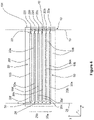
FIG. 5 schematic illustrations of the A-A cross sections of a heat exchanger of the example embodiments ofFigures 1-2 . -
FIG. 6 schematic illustrations of the A-A cross sections of a heat exchanger of the example embodiments ofFigures 1-2 . -
FIG. 7 schematic illustrations of an embodiment ofsection 40Figure 6 . -
FIG. 8 schematic illustrations of an embodiment ofsection 40Figure 6 . -
FIG. 9 schematic illustrations of an embodiment ofsection 60Figure 6 . -
FIG. 10 schematic illustrations of an embodiment ofsection 80Figure 6 . - A detailed description of one or more embodiments of the disclosed apparatus and method are presented herein by way of exemplification and not limitation with reference to the Figures.
-
Figures 1-3 include schematic illustrations of aheat exchanger 100 formed from a pair of metal plates (101, 102). The plates (101, 102) are joined along corresponding mating surfaces and form aseam 110 therebetween. Theheat exchanger 100 includes afluid inlet 10 andfluid outlet 30. The metal plates (101, 102) can be formed of any metal, e.g., aluminum, aluminum alloy, steel, steel alloy, copper, copper alloy, or the like. The metal plates (101, 102) can abut one another along a side and can be joined using any suitable means such as brazing, welding, clamping, compressing, bolting, and the like. The mating surfaces of the metal plates (101, 102) can be configured to correspond to one another, e.g., to fit together and seal the fluid circuit therebetween. The mating surfaces of the metal plates (101, 102) can include precision surfaces formed from a process having highly accurate and precise dimensional control, such as through computer numerical control (CNC) machining process and/or net shape, or near net shape manufacturing process. Optionally a sealing material can be disposed between the metal plates (101, 102) to aide in preventing leakage from the fluid circuit. - As illustrated in the
heat exchanger 100 ofFigure 1 , the metal plates (101, 102) can have different thicknesses (e.g., in the z-dimension of the attached figures). Afirst metal plate 101 can be thicker than asecond metal plate 102. In such an embodiment, thefirst metal plate 101 can include a plurality of connectedrecesses 105, discussed further below, formed into its thickness dimension. Theserecesses 105 in thefirst plate 101 can substantially form three surfaces of the fluid passages formed between the plates and thesecond metal plate 102 can substantially form the fourth surface of the fluid passages. For example, recesses in thefirst plate 101 can substantially form about 60% to about 90% of the wetted perimeter of the fluid passage formed between the plates, or about 65% to about 80%, or about 70% to about 75%, or about 75%. - A further example of the
heat exchanger 100 can be found inFigure 2 which illustrates how the metal plates (101, 102) can have substantially equal thicknesses (e.g., in the z-dimension of the attached figures). The thickness of thefirst metal plate 101 can be substantially the same (e.g., such as allowing for industrially acceptable manufacturing tolerances) as the thickness of thesecond metal plate 102. For example, both thefirst metal plate 101 and thesecond metal plate 102 can each include a plurality of connectedrecesses 105 formed into their thickness dimensions (e.g., in the z-dimension of the attached figures). The arrangement of the connectedrecesses 105 on the two metal plates (101, 102) can mirror one another such that when joined the recesses form approximately equal portions of the wetted perimeter of the fluid passages formed therebetween. - The inventors further contemplate structures that have non-equal depth of recesses between the two metal plates (101, 102) such that one plate has a fractional depth of 1% to 49% of the total depth of the fluid passages formed between the plates and the other plate has the corresponding fractional depth from 99% to 51%.
- The
fluid inlet 10 and thefluid outlet 30 ofheat exchanger 100 can be any shape, such as in the depth dimension of the plate (e.g., in the z-x plane of the attached figure), including the shape of a circle, oval, triangular, square, rectangular, or any simple polygonal shape or portion thereof. The perimeter of thefluid inlet 10,fluid outlet 30, or both, can be formed from a recess (e.g., of the plurality of connected recesses 105), in one or both metal plates (101, 102), which extends to an edge of the plate(s), as illustrated inFigures 1-2 . Alternatively, thefluid inlet 10,fluid outlet 30, or both can be disposed in one of the two metal plates (101, 102) as shown inFigure 3 . Thefluid inlet 10 can be configured to connect a first heat transfer fluid (e.g., refrigerant) source (e.g., condenser of a vapor compression system) to theinlet manifold 12 using any suitable mechanical connection (e.g., compression coupling, brazing, welding, and the like). Thefluid outlet 30 can be configured to connect a first heat transfer fluid sink (e.g., evaporator of a vapor compression system) to theoutlet manifold 28 using any suitable mechanical connection (e.g., compression coupling, brazing, welding, and the like). - As illustrated in
Figure 3 , the perimeter of thefluid inlet 10, thefluid outlet 30, or the perimeters of each can be formed entirely within one of the metal plates (101, 102), such as in a casting, machining, drilling, or similar process where the corresponding other metal plate does not form any of said perimeter. For example, one of the metal plates (101, 102) can entirely form the perimeter of one of thefluid inlet 10 or thefluid outlet 30, and the corresponding other plate can form the other. Still further, the metal plates (101, 102) can entirely form the perimeter of one of thefluid inlet 10 or thefluid outlet 30 and partially forms the perimeter of the other (e.g., cooperating with the other plate to form the perimeter of theother fluid inlet 10 or fluid outlet 30). -
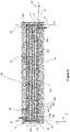
Figure 4-6 are schematic illustrations of the A-A cross sections ofFigures 1-3 . One, or both, metal plates (101, 102) can include a plurality ofconnected recesses 105 which can form a fluid circuit between the metal plates (101, 102) when the plates are joined. For example, afirst metal plate 101 having a plurality ofconnected recesses 105 can be joined to a secondflat metal plate 102 that does not have any recesses to form theheat exchanger 100. In another example, afirst metal plate 101 and asecond metal plate 102 can each have a plurality ofconnected recesses 105 which mirror one another such that when joined the connected recesses form the fluid circuit. Mating surfaces 106 can substantially border the plurality of connected recesses 105. Optionally, the mating surfaces 106 can include raised or recessed portions, or other engagement features to aid in alignment of the plates prior to joining. - The plurality of
connected recesses 105 can have any shape in the depth dimension (e.g., as projected onto a z-y plane of the attached figures, into the plate), including semi-circular, semi-oval, triangular, square, rectangular, or any simple polygonal shape or portion thereof. For example, the recesses in afirst metal plate 101 can be substantially rectangular such that substantially rectangular fluid passages are formed when it is joined to a mating second flat metal plate 102 (e.g., having no recesses). In another example, the recesses in afirst metal plate 101 can be substantially square such that substantially square fluid passages are formed when it is joined to a mating second flat metal plate 102 (e.g., having no recesses). In another example, both afirst metal plate 101 and asecond metal plate 102 can include corresponding square shaped recesses 105 (e.g., mirroring one another) such that rectangular fluid passages are formed when the plates are joined. In another example, both afirst metal plate 101 and asecond metal plate 102 can include corresponding rectangularly shaped recesses 105 (e.g., mirroring one another) such that square fluid passages are formed when the plates are joined. In another example, both afirst metal plate 101 and asecond metal plate 102 can include corresponding semi-circle shaped recesses 105 (e.g., mirroring the recesses in the first plate) such that circular fluid passages are formed when the plates are joined. - The fluid circuit formed between the plates can be fluidly connected to the
fluid inlet 10 and thefluid outlet 30 and include aninlet manifold 12, anoutlet manifold 28, and a plurality offluid passages 20 extending between and fluidly connecting theinlet manifold 12 andoutlet manifold 28. Theinlet manifold 12 andoutlet manifold 28 can be arranged in any shape sufficient to deliver fluid from thefluid inlet 10 to thefluid passages 20. For example, theinlet manifold 12, theoutlet manifold 28, or both can include amajor axis 13 which extends perpendicular to thefluid passages 20. In further example, theinlet manifold 12, theoutlet manifold 28, or both can include one or more turns 15 (e.g., such as forming a J or L shape in the x-y plane of the attached figures) where the manifold extends along aminor axis 11 and amajor axis 13. - To facilitate draining fluid from the heat exchanger 100 (e.g., after the system is shutdown, in a service mode, or the like), the
fluid passages 20 can be configured having atilt angle 35. Thetilt angle 35 can be defined as the angle between aplane 18 extending perpendicular to the direction of gravity (e.g., perpendicular to themajor axis 13 of the inlet manifold 12) and amajor axis 23 of a fluid passage of the plurality offluid passages 20. Theheat exchanger 100 can be configured having atilt angle 35 of up to about 10°, for example about 9°, or about 8° or about 7° or about 6° or about 5°, or about 4° or about 3°, or about 2°, or about 1°. -
Figures 7-8 are schematic illustrations of embodiments of the detail ofsection 40 ofFigure 6 . The flow constrictions 22 can be located in anend wall 41 offluid passages 20 in any way. For example, theflow constrictions 22 can be vertically centered in theend wall 41 offluid passages 20 as shown inFigure 7 . To aid in draining fluid from the heat exchanger 100 (e.g., when the system is shutdown, in a service mode, or the like),flow constrictions 22 can be off centered in theend wall 41 offluid passages 20. For example, as inFigure 8 , aflow constriction 22 can be positioned such that alower wall 43 of theflow passage 20 transitions into aninner wall 47 of theinlet manifold 12 along a surface that slopes continuously downward (e.g., toward the fluid inlet 10). -
Figure 9 is a schematic illustration of the detail ofsection 60 ofFigure 6 showing afluid conduit 70 fluidly connected to thefluid inlet 10 ofheat exchanger 100. Theheat exchanger 100 can be configured for a flush transition from theinner walls 71 of thefluid conduit 70 to theinner walls 47 of theinlet manifold 12. For example, arecess 73 disposed in thefluid inlet 10 can be sized to accommodate the thickness of thefluid conduit 70. -
Figure 10 is a schematic illustration of the detail ofsection 80 ofFigure 6 showing afluid conduit 70 fluidly connected to thefluid outlet 30 ofheat exchanger 100. Theheat exchanger 100 can be configured for a flush transition from theinner walls 47 of theoutlet manifold 12 to theinner walls 71 of thefluid conduit 70. For example, arecess 74 disposed in thefluid outlet 30 can be sized to accommodate the thickness of thefluid conduit 70. - The fluid circuit can include a plurality of
flow constrictions 22 which can be used to set, at least in part, the flow resistance characteristics for each of the parallel flowpaths 50 (e.g., unique flow routes extending between thefluid inlet 10 and the fluid outlet 30) through theheat exchanger 100. The flow constrictions 22 can be formed as part of the plurality ofconnected recesses 105, integral to one or both metal plates (101, 102). For example, afluid passage 20 can include, or abut, a section of reduced hydraulic diameter defining theflow constriction 22. In another example, theflow constrictions 22 can be formed separately and be inserted between the metal plates (101, 102) before they are joined. For example, thefluid passage 20 can include one or more slots, notches, recesses, or other cooperating features (e.g. disposed along portions of the perimeter of thefluid passage 20, abutting an end of thefluid passage 20, or the like) to allow a flow constriction 22 (e.g., an orifice plate, orifice body, or the like) to be inserted into said slot, notch, recess or other cooperating feature before the metal plates (101, 102) are joined. The flow constrictions 22 can be disposed in the fluid circuit at the inlet to thefluid passages 20. The flow constrictions 22 can be disposed between theinlet manifold 12 and the plurality offluid passages 20. The flow constrictions 22 can extend for a constriction length (e.g., measured in the direction that fluid flows through the constriction, substantially along the x-dimension in the attached figures or along themajor axis 23 of the parallel fluid passage 20), a constriction width (e.g., measured in a direction perpendicular to that direction that fluid flows through the constriction, substantially along the y-dimension in the attached figures), and a constriction depth (e.g., measured in a direction perpendicular to that direction that fluid flows through the constriction, substantially along the z-dimension in the attached figures). The flow constriction length divided by the hydraulic diameter of thefluid passage 20 can be from about 2 to about 4, or from about 2.5 to about 3.5, or from about 2.7 to about 3.1, or from about 2.75 to about 2.9, or from about 2.77 to about 2.85, or about 2.8. The constriction depth of one or more of the plurality offlow constrictions 22 can be different than the depth of thecorresponding flow passage 20. For example, the constriction depth of aflow constriction 22 can be from about 2% to about 75% of the depth of thecorresponding flow passage 20, or from about 2% to about 50%, or from about 2% to about 25%, or from about 2% to about 20%, or from about 2% to about 15%, or from about 2% to about 12%, or from about 2% to about 10%, or from about 4% to about 15%, or from about 5% to about 15%, or from about 6% to about 15%, or from about 6% to about 12% or from about 6% to about 10 %. - Individual flow constrictions of the plurality of
flow constrictions 22 can have a ratio of flow constriction hydraulic diameter to corresponding fluid passage hydraulic diameter which increases with increasing distance from thefluid inlet 10. For example, afirst flow constriction 22a of a plurality offlow constrictions 22 can be disposed closest to thefluid inlet 10 and can have the smallest ratio of flow constriction hydraulic diameter to corresponding fluid passage hydraulic diameter of the plurality offlow constrictions 22. Further, alast flow constriction 22f can be disposed furthest away from theinlet 10 and can have the largest ratio of flow constriction hydraulic diameter to corresponding fluid passage hydraulic diameter of the plurality offlow constrictions 22. - The ratio of flow constriction hydraulic diameter to corresponding fluid passage hydraulic diameter can be stepped throughout the
heat exchanger 100. The said ratio can change from afirst group 25a offlowpaths 50 to asecond group 25b offlowpaths 50. Said ratio can increase equally for allflowpaths 50 in each group 25 of theheat exchanger 100 with increasing distance from thefluid inlet 10. For example, aheat exchanger 100 configured with two flow resistance steps therethrough can include afirst group 25a of two or moreadjacent flowpaths 50 having substantially the same flow resistance characteristics (e.g., flowrate to pressure-drop relationship) and asecond group 25b of two or moreadjacent flowpaths 50 having substantially the same flow resistance characteristics that are different from those of thefirst group 25a (i.e., less restrictive to flow therethrough comparted to thefirst group 25a). Thefirst group 25a can include twoadjacent flowpaths 50 having substantially equal fluid flow resistance characteristics. For example, thefirst group 25a can include afirst flowpath 50a through thefirst flow constriction 22a and acorresponding fluid passage 20a and asecond flowpath 50b through asecond flow constriction 22b and acorresponding fluid passage 20b having substantially equal fluid flow resistance characteristics. The ratio of flow constriction hydraulic diameter to corresponding fluid passage hydraulic diameter for thefirst group 25a (adjacent the fluid inlet 10) can be from about 0.3 to about 0.5, or from about 0.35 to about 0.49, or from about 0.40 to about 0.48, or from about 0.43 to about 0.47, or from about 0.44 to about 0.46, or about 0.45. For example, the ratio of flow constriction hydraulic diameter to corresponding fluid passage hydraulic diameter for thefirst group 25a can be about 0.30, or about 0.31, or about 0.32, or about 0.33, or about 0.34, or about 0.35, or about 0.36, or about 0.37, or about 0.38, or about 0.39, or about 0.40, or about 0.41, or about 0.42, or about 0.43, or about 0.44, or about 0.45, or about 0.46, or about 0.47, or about 048, or about 0.49, or about 0.50. - The ratio of flow constriction hydraulic diameter to corresponding fluid passage hydraulic diameter for groups 25 of
flowpaths 50 can increase by a scaling factor with increasing distance from thefluid inlet 10. This scaling factor can be a multiplier which can be used to scale the ratio of flow constriction hydraulic diameter to corresponding fluid passage hydraulic diameter for subsequent groups 25 offlowpaths 50 as the groups 25 are located further away from thefluid inlet 10. The scaling factor can be from about 1.2. to about 1.5, or about 1.25 to about 1.45, or about 1.27 to about 1.4, or from about 1.28 to about 1.35, or from about 1.29 to about 1.32. For example, the scaling factor can be about 1.20, or about 1.21, or about 1.22, or about 1.23, or about 1.24, or about 1.25, or about 1.26, or about 1.27, or about 1.28, or about 1.29, or about 1.30, or about 1.31, or about 1.32, or about 1.33, or about 1.34, or about 1.35, or about 1.36, or about 1.37, or about 1.38, or about 1.39, or about 1.40, or about 1.41, or about 1.42, or about 1.43, or about 1.44, or about 1.45, or about 1.46, or about 1.47, or about 1.48, or about 1.49, or about 1.50. - The scaling factor can be used to increase the ratio of flow constriction hydraulic diameter to corresponding fluid passage hydraulic diameter which can include increasing the flow area of the
flow constriction 22 or reducing the flow area of thecorresponding flow passage 20. For example, the scaling factor can be used to increase the flow area (e.g., hydraulic diameter) of theflow constrictions 22 in each group 25 offlowpaths 50 as the groups are located further from thefluid inlet 10. Increasing the size of theflow constrictions 22 can include enlarging the cross-sectional perimeter (e.g., in a plane perpendicular to the average flow vector of the fluid flowing therethrough) or changing its shape to increase the cross-sectional flow area of the constriction. Further, afirst group 25a offlowpaths 50 can have a first flow resistance characteristic (e.g., pressure drop at a given flow rate) and asecond group 25b offlowpaths 50 can have a second flow resistance characteristic where the second flow resistance characteristic equals between 1.2 and 1.5 times the first flow resistance characteristic. For example, theflowpaths 50 in thefirst group 25a can have a ratio of flow constriction hydraulic diameter to corresponding fluid passage hydraulic diameter equal to about 0.45 while said ratio is scaled up by a scaling factor of about 1.39 to about 0.625 forflowpaths 50 in thesecond group 25b. Still further, said ratio can be scaled up to about 0.75 in athird group 25c offlowpaths 50 by applying a scaling factor of 1.2 to said ratio in thesecond group 25b (the adjacent group closer to the fluid inlet 10). - The
heat exchanger 100 can include from four to twentyfluid passages 20 and corresponding flow constrictions 22 (e.g., fluidically in-line with the fluid passage 20). For example, theheat exchanger 100 can include sixfluid passages 20 and corresponding flow constrictions 22. As inFigure 5 , aheat exchanger 100 having sixfluid passages 20 can be configured with two groups (25a, 25b) offlowpaths 50. Afirst group 25a can include the two flowpaths (50a, 50b) disposed closest to thefluid inlet 10 and asecond group 25b can include the four flowpaths (50c, 50d, 50e, 50f) disposed furthest from thefluid inlet 10. The flow characteristics of the two flowpaths (50a, 50b) of thefirst group 25a can be substantially equal, e.g., due to having substantially equal ratios of flow constriction hydraulic diameter to fluid passage hydraulic diameter, the fluid passages (20a, 20b) and flow constrictions (22a, 22b) of thegroup 25a having substantially similar geometric construction (e.g., shape, dimensions, and the like), a combination thereof, or the like. The flow characteristics of the four flowpaths (50c, 50d, 50e, 50f) of thesecond group 25b can be substantially equal, e.g., due to having substantially equal ratios of flow constriction hydraulic diameter to fluid passage hydraulic diameter, the fluid passages (20c, 20d, 20e, 20f) and flow constrictions (22c, 22d, 22e, 22f) of thegroup 25b having substantially similar geometric construction (e.g., shape, dimensions, and the like), a combination thereof, or the like - The
fluid passages 20 can be arranged substantially parallel to one another. Thefluid passages 20 can have a substantiallyequal spacing distance 27 therebetween (e.g., in the x-y plane of the attached figures). Optionally, thespacing distance 27 can be varied throughout theheat exchanger 100. For example, thespacing distance 27 divided by the average hydraulic diameter of the two adjacent fluid passages, can be from about 1.25 to about 5, or from about 1.5 to about 4.5, or from about 1.75 to about 4.25, or from about 2.0 to about 4.0, or from about 2.1 to about 3.5, or from about 2.15 to about 3.35, or from about 2.2 to about 3.2. - The length of the
fluid passages 20, divided by the hydraulic diameter of thefluid passage 20 can be from about 25 to about 250, or from about 30 to about 200, or from about 40 to about 180, or from about 50 to about 150, or from about 60 to about 140, or from about 75 to about 130, or from about 90 to about 120, or from about 100 to about 120, or from about 105 to about 115, or about 110, or about 111, or about 112. - The
heat exchanger 100 can be configured for operation in a substantially vertical orientation. For example, a firstmajor axis 13 of theinlet manifold 12 and a secondmajor axis 29 of theoutlet manifold 28 can extend substantially vertically (e.g., substantially aligned with the direction of Earth's gravitational force) and the plurality of fluid passages can be arranged one atop of the other, where thefluid inlet 10 is disposed below thefluid outlet 30. In this configuration a flow direction of a heat transfer fluid substantially opposes gravity as the heat transfer fluid traverses theheat exchanger 100 from thefluid inlet 10 to thefluid outlet 30. In the vertical orientation, includingflow constrictions 22 as described herein can overcome the gravitational effect which tends to bias vapor phase refrigerant toward the top of theheat exchanger 100. - The
heat exchanger 100 can be configured for mounting one or more powerelectronic modules 200 directly to the surface of one of both metal plates (101, 102). For example, one or both metal plates (101, 102) of theheat exchanger 100 can include fastening features (e.g., threads for receiving bolts or screws, clips, exposed bolt or screw shafts, tabs, slots, notches, or other engagement features) disposed along its outer surface for securing the one or morepower electronics modules 200 to theheat exchanger 100 in a way that facilitates the transfer of thermal energy away from thepower electronics module 200. The term "power electronic module" as used herein can refer to an electronic component which can provide a controlled output power by modulating and/or converting a supplied input power (e.g., a variable frequency drive, power rectifier, power converter, and the like). Such a powerelectronic module 200 can be used to control the speed of a compressor and/or the speed of the fan of a vapor compression system (e.g., chiller) based on various predetermined system conditions. - The one or more
power electronics modules 200 can be attached to a circuit card or board on which various other electrical components are mounted (e.g., compressor and/or fan speed control related components). The reliability and life of the one or more powerelectronic modules 200 can dependent upon precluding such components from operating at high temperatures and/or precluding their exposure to thermal shock. Because these components can generate a large amount of heat, they can have a heat sink interface (e.g., exposed copper surface) which is designed for attachment to a heat sink through use of previously described fastening features. When secured in thermal communication with theheat exchanger 100 the heat generated by the one or morepower electronics module 200 can be removed through the heat sink interface to keep the one or morepower electronics module 200 cooled below its maximum allowable operating temperature (e.g., 150 °F). Optionally, insulation can be disposed along exposed surfaces of the heat exchanger 100 (e.g., surfaces not in thermal communication with one or more power electronics modules 200) to hinder heat absorption from ambient conditions or heat sources other than the one or morepower electronics modules 200. Optionally, heat transfer fins can be attached in thermal communication with one or more outer surfaces of theheat exchanger 100. - The heat transfer fluid (e.g., refrigerant) provided to the
heat exchanger 100 can originate from the condenser of a vapor compression cycle and can enter the heat exchanger in a liquid phase with 0% vapor quality. The presently disclosedheat exchanger 100 can be operated to ensure the vapor quality of refrigerant exiting thefluid outlet 30 has a vapor quality of from about 35% to about 65%, or from about 40% to about 60%, or from about 45% to about 55%, or about 50%. - In an example embodiment the
heat exchanger 100 can have a length (e.g., measured along the x-axis dimension in the attached figures) of about 900 mm, a width (e.g., measured along the z-axis dimension in the attached figures) of about 27 mm and a height (e.g., measured along the y-axis dimension in the attached figures) of about 200 mm. Theheat exchanger 100 can comprise sixfluid passages 20 having a hydraulic diameter of about 7.2 millimeters (mm). The length of theflow passages 20 can be about 800 mm and the spacing distance betweenadjacent flow passages 20 can vary from about 15 mm to about 23 mm. The twoflow passages 20 disposed closest to thefluid inlet 10 can be grouped together into afirst group 25a where each flowpath 50 within thefirst group 25a includes aflow constriction 22 having a hydraulic diameter or about 3.25 mm. The remaining four flow passages 20 (those further away from the fluid inlet 10) can be grouped together into a second group 26b where each flowpath 50 within thesecond group 25b includes aflow constriction 22 having a hydraulic diameter that is equal to about 1.39 times the hydraulic diameter of the flow constrictions in thefirst group 25a, or about 4.5 mm. The flow constrictions in bothgroups inlet manifold 12 andoutlet manifold 28 can each have a hydraulic diameter of about 12.25 mm. - Table 1 summarizes computation fluid dynamics (CFD) modeling results showing a comparison between a first heat exchanger (Heat Exchanger 1) having no
flow constrictions 22 and a second heat exchanger (Heat Exchanger 2) havingflow constrictions 22 disposed fluidly in-line with theflow passages 20 as described herein. In this example, theflow constrictions 22 reduced the standard deviation of flow rate through the parallel flow passages from about 11.7% of total flow inHeat Exchanger 1 to about 6.1% of total flow in Heat Exchanger 2, corresponding to a reduction of more than 90%. Further, the largest flow difference between flow passages was reduced from 29% of total flow in Heat Exchanger 1 (betweenPassage 1 and Passage 5) to 18% of total flow in Heat Exchanger 2 (between Passage 3 and Passage 6), corresponding to a reduction of about 38%.Table 1 - Heat Exchanger Comparison % of Total Flow to Passage 1% of Total Flow to Passage 2 % of Total Flow to Passage 3 % of Total Flow to Passage 4 % of Total Flow to Passage 5 % of Total Flow to Passage 6 Standard Deviation Heat Exchanger 1 30 28 22.5 14 1 1.5 11.7 Heat Exchanger 2 20.5 19.5 23.5 19 11.5 5.5 6.1 - The term "about" is intended to include the degree of error associated with measurement of the particular quantity based upon the equipment available at the time of filing the application.
- The terminology used herein is for the purpose of describing particular embodiments only and is not intended to be limiting of the present disclosure. As used herein, the singular forms "a", "an" and "the" are intended to include the plural forms as well, unless the context clearly indicates otherwise. It will be further understood that the terms "comprises" and/or "comprising," when used in this specification, specify the presence of stated features, integers, steps, operations, elements, and/or components, but do not preclude the presence or addition of one or more other features, integers, steps, operations, element components, and/or groups thereof.
- While the present disclosure has been described with reference to an exemplary embodiment or embodiments, it will be understood by those skilled in the art that various changes may be made and equivalents may be substituted for elements thereof without departing from the scope of the present disclosure. In addition, many modifications may be made to adapt a particular situation or material to the teachings of the present disclosure without departing from the essential scope thereof. Therefore, it is intended that the present disclosure not be limited to the particular embodiment disclosed as the best mode contemplated for carrying out this present disclosure, but that the present disclosure will include all embodiments falling within the scope of the claims.
Claims (15)
- A heat exchanger comprising a pair of metal plates (101, 102) joined along corresponding mating surfaces (106), wherein at least one of the metal plates (101, 102) comprises a plurality of connected recesses (105) which form a fluid circuit between the plates when the plates are joined, wherein the fluid circuit comprises an inlet (10), an inlet manifold (12), an outlet (30), an outlet manifold (28), and a plurality of flowpaths (50) extending between and fluidly connecting the inlet manifold (12) and outlet manifold (28), wherein one or more of the plurality of flowpaths comprise a fluid passage (20) and a flow constriction (22), and wherein a ratio of the hydraulic diameter of the flow constriction (22) to the hydraulic diameter of the fluid passage (20) increases with increasing distance from the inlet (10).
- The heat exchanger of Claim 1, wherein the heat exchanger is configured for operation in a substantially vertical orientation, wherein a major axis (13) of the inlet manifold (12) and a major axis (13) of the outlet manifold (28) extend substantially vertically, and the plurality of fluid passages (20) are arranged one atop of the other, and wherein the inlet (10) is disposed below the outlet (30) such that during operation a flow direction of a refrigerant through the inlet and outlet manifolds opposes gravity.
- The heat exchanger of Claim 1 or 2, wherein a first flow constriction (22a) is disposed in the fluid passage (20) closest to the inlet (10) and comprises a ratio of hydraulic diameter of the flow constriction to the hydraulic diameter of the fluid passage (20) of between 0.3 and 0.5 inclusive of end points.
- The heat exchanger of Claim 1, 2 or 3, wherein the flow constrictions (22) are disposed between the fluid passages (20) and the inlet manifold (12).
- The heat exchanger of any preceding Claim, wherein both plates (101, 102) comprise correspondingly arranged connected recess (105) that when joined form the fluid circuit.
- The heat exchanger of any preceding Claim, wherein a first group (25a) of two or more adjacent flowpaths (50) closest to the inlet (10) comprise a flow constriction having a first flow constriction hydraulic diameter and a second group (25b) of two or more adjacent flowpaths (50), not in the first group (25a), comprise a flow constriction having a second flow constriction hydraulic diameter, and wherein the second flow constriction hydraulic diameter is greater than the first flow constriction hydraulic diameter; optionally
wherein the second flow constriction hydraulic diameter is equal to from 1.2 to 1.5 times the first flow constriction hydraulic diameter. - The heat exchanger of Claim 6, further comprising a third group (25c) of two or more adjacent flowpaths (50), not in the first group (25a) or second group (25b), comprising a flow constriction having a third flow constriction hydraulic diameter, and wherein the third flow constriction hydraulic diameter is greater than each the first flow constriction hydraulic diameter and the second flow constriction hydraulic diameter; optionallywherein the third flow constriction hydraulic diameter is equal to from 1.2 to 1.5 times the second flow constriction hydraulic diameter; orwherein the second flow constriction hydraulic diameter is equal to from 1.2 to 1.5 times the first flow constriction hydraulic diameter and the third flow constriction hydraulic diameter is equal to between 1.2 and 1.5 times the second flow constriction hydraulic diameter.
- The heat exchanger of any preceding Claim, comprising greater than two groups of adjacent flowpaths (50) through the heat exchanger, each flowpath (50) comprising a fluid passage (20) and a flow constriction (22), wherein the flow constrictions in flowpaths of groups further distanced from the inlet (10) comprises a flow constriction hydraulic diameter equal to from 1.2 to 1.5 times the flow constriction hydraulic diameter of the flow constrictions in the flowpaths of groups immediately adjacent and closer to the inlet (10).
- The heat exchanger of any preceding Claim, wherein during operation, the refrigerant entering the inlet (10) is a single phase liquid refrigerant having a vapor quality equal to zero, and the refrigerant exiting the outlet (30) is a two-phase mixture having a vapor quality between 0.4 and 0.6, inclusive of end points.
- The heat exchanger of any preceding Claim, further comprising a power electronics module mounting feature disposed on a face of one of the metal plates (101, 102), and wherein the face is disposed on a side of the metal plate (101, 102) opposite the mating surface (106).
- The heat exchanger of any preceding Claim, wherein the connected recesses (105) forming the inlet (10) and outlet (30) each comprise an engagement feature for securing a fluid conduit thereto.
- The heat exchanger of any preceding Claim, wherein the plates (101, 102) are joined by a weld and wherein the weld forms a seal (110) between the plates (101, 102) along at least a portion of the mating surfaces (106); and/or
wherein the plates (101, 102) are joined by a compression mechanism configured to hold the plates together. - The heat exchanger of any preceding Claim, further comprising a seal material disposed between the plates (101, 102) for preventing leakage from the fluid circuit.
- The heat exchanger of any preceding Claim, wherein the fluid passage (20) extends at a tilt angle of less than or equal to 10°.
- A refrigerant cycle machine comprising:a primary refrigeration circuit configured for passing a refrigerant through a compressor, a heat rejecting heat exchanger, an expansion valve, and a heat absorbing heat exchanger in a serial flow arrangement,an expansion valve bypass circuit for diverting at least a portion of the refrigerant exiting the condenser of the primary refrigeration circuit to an electronics cooler and returning the portion of the refrigerant to the evaporator, and wherein the electronics cooler comprises the heat exchanger of any preceding claim and wherein the portion of the refrigerant is directed through the heat exchanger to cool one or more power electronics modules (200) attached in thermal communication thereto; optionallywherein the expansion valve bypass circuit comprises two electronics coolers disposed in parallel flow arrangement, one for cooling a power rectifier and the other for cooling an inverter.
Applications Claiming Priority (1)
| Application Number | Priority Date | Filing Date | Title |
|---|---|---|---|
| US202163201968P | 2021-05-20 | 2021-05-20 |
Publications (2)
| Publication Number | Publication Date |
|---|---|
| EP4093169A1 true EP4093169A1 (en) | 2022-11-23 |
| EP4093169B1 EP4093169B1 (en) | 2026-04-01 |
Family
ID=81750605
Family Applications (1)
| Application Number | Title | Priority Date | Filing Date |
|---|---|---|---|
| EP22174616.7A Active EP4093169B1 (en) | 2021-05-20 | 2022-05-20 | Heat exchanger for power electronics |
Country Status (3)
| Country | Link |
|---|---|
| US (1) | US11988421B2 (en) |
| EP (1) | EP4093169B1 (en) |
| CN (1) | CN115379715A (en) |
Families Citing this family (1)
| Publication number | Priority date | Publication date | Assignee | Title |
|---|---|---|---|---|
| US20250008699A1 (en) * | 2023-06-30 | 2025-01-02 | Laurel Technologies Partnership | Immersion tank for cooling electronics |
Citations (4)
| Publication number | Priority date | Publication date | Assignee | Title |
|---|---|---|---|---|
| US20050285261A1 (en) * | 2004-06-25 | 2005-12-29 | Prasher Ravi S | Thermal management arrangement with channels structurally adapted for varying heat flux areas |
| US20090250195A1 (en) * | 2006-06-14 | 2009-10-08 | Toyota Jidosha Kabushiki Kaisha | Heat sink and cooler |
| US20120097374A1 (en) * | 2010-10-21 | 2012-04-26 | Raytheon Company | Maintaining thermal uniformity in micro-channel cold plates with two-phase flows |
| EP2568789A1 (en) * | 2011-09-06 | 2013-03-13 | ABB Research Ltd. | Heat exchanger |
Family Cites Families (48)
| Publication number | Priority date | Publication date | Assignee | Title |
|---|---|---|---|---|
| US6116040A (en) | 1999-03-15 | 2000-09-12 | Carrier Corporation | Apparatus for cooling the power electronics of a refrigeration compressor drive |
| FR2817300B1 (en) | 2000-11-24 | 2005-09-23 | Valeo Climatisation | COMPRESSOR FOR A CLIMATE SYSTEM FOR THE COCKPIT OF A MOTOR VEHICLE |
| US6497554B2 (en) | 2000-12-20 | 2002-12-24 | Carrier Corporation | Fail safe electronic pressure switch for compressor motor |
| LU90890B1 (en) | 2002-02-15 | 2003-08-18 | Delphi Tech Inc | Cooling of electronics in an electrically driven refrigeration system |
| JP3896472B2 (en) | 2002-09-04 | 2007-03-22 | 株式会社日立製作所 | Refrigeration equipment |
| US6688124B1 (en) | 2002-11-07 | 2004-02-10 | Carrier Corporation | Electronic expansion valve control for a refrigerant cooled variable frequency drive (VFD) |
| US7164242B2 (en) | 2004-02-27 | 2007-01-16 | York International Corp. | Variable speed drive for multiple loads |
| US7003971B2 (en) | 2004-04-12 | 2006-02-28 | York International Corporation | Electronic component cooling system for an air-cooled chiller |
| US7412842B2 (en) | 2004-04-27 | 2008-08-19 | Emerson Climate Technologies, Inc. | Compressor diagnostic and protection system |
| US20070186581A1 (en) | 2006-02-14 | 2007-08-16 | Ingersoll-Rand Company | Compressor cooling system |
| US8539786B2 (en) | 2007-10-08 | 2013-09-24 | Emerson Climate Technologies, Inc. | System and method for monitoring overheat of a compressor |
| US8234881B2 (en) | 2008-08-28 | 2012-08-07 | Johnson Controls Technology Company | Multichannel heat exchanger with dissimilar flow |
| US8209057B2 (en) | 2008-11-17 | 2012-06-26 | Liebert Corporation | System and method for forming universal control panel |
| US20100147492A1 (en) | 2008-12-10 | 2010-06-17 | Ronald David Conry | IGBT cooling method |
| US10024321B2 (en) | 2009-05-18 | 2018-07-17 | Emerson Climate Technologies, Inc. | Diagnostic system |
| JP4985723B2 (en) | 2009-07-27 | 2012-07-25 | 三菱電機株式会社 | Air conditioner |
| EP2465138B1 (en) | 2009-08-10 | 2016-11-23 | Fuji Electric Co., Ltd. | Semiconductor module and cooling unit |
| WO2012158653A2 (en) | 2011-05-13 | 2012-11-22 | Ietip Llc | System and methods for cooling electronic equipment |
| US9528718B2 (en) | 2011-08-10 | 2016-12-27 | Carrier Corporation | HVAC motor load balancing |
| US10184701B2 (en) | 2011-09-16 | 2019-01-22 | Danfoss A/S | Motor cooling and sub-cooling circuits for compressor |
| US8950201B2 (en) | 2012-03-30 | 2015-02-10 | Trane International Inc. | System and method for cooling power electronics using heat sinks |
| JP2013216216A (en) | 2012-04-10 | 2013-10-24 | Ntn Corp | Cooling structure of inverter device |
| WO2014116760A1 (en) | 2013-01-23 | 2014-07-31 | Trane International Inc. | Variable frequency drive operation to avoid overheating |
| CN105190204B (en) | 2013-03-11 | 2017-05-31 | 特灵国际有限公司 | Control and Operation of Variable Frequency Drives |
| CN203353466U (en) | 2013-07-01 | 2013-12-25 | 深圳市兴日生实业有限公司 | Variable frequency driving water temperature regulating machine |
| JP2016513766A (en) * | 2013-12-05 | 2016-05-16 | グアンドン メイジ コムプレッサ カンパニー リミテッド | Rotary compressor, compressor for the same, air conditioner |
| JP6342727B2 (en) | 2014-06-24 | 2018-06-13 | ヤンマー株式会社 | Heat pump chiller |
| US9476626B2 (en) | 2014-08-29 | 2016-10-25 | Emerson Climate Technologies, Inc. | Variable speed compressor control with lost rotor mitigation |
| US20160123637A1 (en) * | 2014-10-29 | 2016-05-05 | Alliance For Sustainable Energy, Llc | Two-phase heat exchanger for cooling electrical components |
| US10197052B2 (en) | 2015-05-11 | 2019-02-05 | Littelfuse, Inc. | Variable frequency drive apparatus |
| US9819159B2 (en) | 2015-10-26 | 2017-11-14 | Lewis T. Smith | Low profile variable frequency controller with cooling and process |
| US10724799B2 (en) * | 2016-03-16 | 2020-07-28 | Mitsubishi Electric Corporation | Heat pump apparatus |
| JP6665655B2 (en) | 2016-04-19 | 2020-03-13 | 株式会社デンソー | Power converter |
| CN205718109U (en) | 2016-05-25 | 2016-11-23 | 南京天加空调设备有限公司 | A kind of chiller of the frequency conversion drive module of convertible frequency air-conditioner |
| US10390466B2 (en) | 2016-07-29 | 2019-08-20 | Schlumberger Technology Corporation | External structure heat sink |
| US10508841B2 (en) | 2016-09-15 | 2019-12-17 | Trane International Inc. | Cooling circuit for a variable frequency drive |
| US10627146B2 (en) | 2016-10-17 | 2020-04-21 | Emerson Climate Technologies, Inc. | Liquid slugging detection and protection |
| WO2018081249A1 (en) * | 2016-10-27 | 2018-05-03 | The Coca-Cola Company | Systems and methods for vacuum cooling a beverage |
| JP7049363B2 (en) | 2017-12-13 | 2022-04-06 | 三菱電機株式会社 | Power converter and air conditioner |
| IT201800007390A1 (en) | 2018-07-20 | 2020-01-20 | COOLING SYSTEM | |
| DE102018213232A1 (en) * | 2018-08-07 | 2020-02-13 | Audi Ag | Method for operating a refrigeration system for a vehicle with a refrigerant circuit having a heat pump function |
| JP7071678B2 (en) * | 2018-09-28 | 2022-05-19 | ダイキン工業株式会社 | Heat exchanger |
| CN109539463A (en) | 2018-11-14 | 2019-03-29 | 珠海格力电器股份有限公司 | Air conditioning system and cooling control method of variable frequency driver of air conditioning system |
| CN111355428B (en) | 2018-12-21 | 2024-05-14 | 上海辰竹仪表有限公司 | Safety torque turn-off circuit and motor control system using same |
| CN209642583U (en) | 2018-12-21 | 2019-11-15 | 上海辰竹仪表有限公司 | Safe torque breaking circuit and its electric machine control system of application |
| KR102128914B1 (en) | 2019-01-11 | 2020-07-08 | 엘지전자 주식회사 | An apparatus and a method for testng a compressor |
| CN211084516U (en) | 2019-09-23 | 2020-07-24 | 珠海格力电器股份有限公司 | Variable frequency drive module cooling structure and air conditioner |
| US11415346B2 (en) * | 2020-04-30 | 2022-08-16 | Trane International Inc. | System and method for common side connections for oversized multislab microchannel heat exchanger |
-
2022
- 2022-05-13 US US17/744,074 patent/US11988421B2/en active Active
- 2022-05-19 CN CN202210543931.0A patent/CN115379715A/en active Pending
- 2022-05-20 EP EP22174616.7A patent/EP4093169B1/en active Active
Patent Citations (4)
| Publication number | Priority date | Publication date | Assignee | Title |
|---|---|---|---|---|
| US20050285261A1 (en) * | 2004-06-25 | 2005-12-29 | Prasher Ravi S | Thermal management arrangement with channels structurally adapted for varying heat flux areas |
| US20090250195A1 (en) * | 2006-06-14 | 2009-10-08 | Toyota Jidosha Kabushiki Kaisha | Heat sink and cooler |
| US20120097374A1 (en) * | 2010-10-21 | 2012-04-26 | Raytheon Company | Maintaining thermal uniformity in micro-channel cold plates with two-phase flows |
| EP2568789A1 (en) * | 2011-09-06 | 2013-03-13 | ABB Research Ltd. | Heat exchanger |
Also Published As
| Publication number | Publication date |
|---|---|
| US20220373236A1 (en) | 2022-11-24 |
| US11988421B2 (en) | 2024-05-21 |
| EP4093169B1 (en) | 2026-04-01 |
| CN115379715A (en) | 2022-11-22 |
Similar Documents
| Publication | Publication Date | Title |
|---|---|---|
| US8726976B2 (en) | Laminated sheet manifold for microchannel heat exchanger | |
| EP1276362B1 (en) | Flattened tube cold plate for liquid cooling electrical components | |
| US10837720B2 (en) | Heat exchanger with aluminum tubes rolled into an aluminum tube support | |
| CN111601489B (en) | Multilayer serial cascade liquid cooling plate | |
| KR20150030235A (en) | A plate heat exchanger with thermally drilled hole | |
| US8839519B2 (en) | Method of making cold chassis for electronic modules | |
| US12520462B2 (en) | Refrigerant cooled heat sink for power electronic modules | |
| EP4093169B1 (en) | Heat exchanger for power electronics | |
| US20210048257A1 (en) | Heat exchanger | |
| KR20240101611A (en) | Cooling system for electronic component racks | |
| US12408311B2 (en) | Combined liquid and air cooled power electronics assembly | |
| US20230262947A1 (en) | Systems for a heat exchanger | |
| JP7650982B2 (en) | Heat exchanger and method for manufacturing the same | |
| EP4174433B1 (en) | Heating ventilation and air conditioning system with heat exchanger for power electronics | |
| US20230127088A1 (en) | Seal for thermal interface material of power electronics modules | |
| EP4398691A1 (en) | Cooling system for power electronics | |
| EP4174432B1 (en) | Enhanced channel configuration for heat exchanger to cool power electronics | |
| US12453043B2 (en) | Mechanically expanded microfin tube liquid cooled heat sink | |
| US20090165489A1 (en) | Refrigeration Condenser for Electronics Cooling and Manufacture Thereof | |
| KR100795269B1 (en) | Heat exchanger and its manufacturing method |
Legal Events
| Date | Code | Title | Description |
|---|---|---|---|
| PUAI | Public reference made under article 153(3) epc to a published international application that has entered the european phase |
Free format text: ORIGINAL CODE: 0009012 |
|
| STAA | Information on the status of an ep patent application or granted ep patent |
Free format text: STATUS: THE APPLICATION HAS BEEN PUBLISHED |
|
| AK | Designated contracting states |
Kind code of ref document: A1 Designated state(s): AL AT BE BG CH CY CZ DE DK EE ES FI FR GB GR HR HU IE IS IT LI LT LU LV MC MK MT NL NO PL PT RO RS SE SI SK SM TR |
|
| STAA | Information on the status of an ep patent application or granted ep patent |
Free format text: STATUS: REQUEST FOR EXAMINATION WAS MADE |
|
| 17P | Request for examination filed |
Effective date: 20230523 |
|
| RBV | Designated contracting states (corrected) |
Designated state(s): AL AT BE BG CH CY CZ DE DK EE ES FI FR GB GR HR HU IE IS IT LI LT LU LV MC MK MT NL NO PL PT RO RS SE SI SK SM TR |
|
| GRAP | Despatch of communication of intention to grant a patent |
Free format text: ORIGINAL CODE: EPIDOSNIGR1 |
|
| STAA | Information on the status of an ep patent application or granted ep patent |
Free format text: STATUS: GRANT OF PATENT IS INTENDED |
|
| RIC1 | Information provided on ipc code assigned before grant |
Ipc: H05K 7/20 20060101AFI20251001BHEP Ipc: F25B 39/02 20060101ALI20251001BHEP Ipc: F28D 9/00 20060101ALI20251001BHEP Ipc: F28D 15/02 20060101ALI20251001BHEP Ipc: F28F 3/12 20060101ALI20251001BHEP Ipc: H01L 23/427 20060101ALI20251001BHEP Ipc: F28D 21/00 20060101ALI20251001BHEP |
|
| INTG | Intention to grant announced |
Effective date: 20251022 |
|
| GRAS | Grant fee paid |
Free format text: ORIGINAL CODE: EPIDOSNIGR3 |
|
| GRAA | (expected) grant |
Free format text: ORIGINAL CODE: 0009210 |
|
| STAA | Information on the status of an ep patent application or granted ep patent |
Free format text: STATUS: THE PATENT HAS BEEN GRANTED |
|
| AK | Designated contracting states |
Kind code of ref document: B1 Designated state(s): AL AT BE BG CH CY CZ DE DK EE ES FI FR GB GR HR HU IE IS IT LI LT LU LV MC MK MT NL NO PL PT RO RS SE SI SK SM TR |
|
| REG | Reference to a national code |
Ref country code: CH Ref legal event code: F10 Free format text: ST27 STATUS EVENT CODE: U-0-0-F10-F00 (AS PROVIDED BY THE NATIONAL OFFICE) Effective date: 20260401 Ref country code: GB Ref legal event code: FG4D |
|
| REG | Reference to a national code |
Ref country code: DE Ref legal event code: R096 Ref document number: 602022033300 Country of ref document: DE |
|
| REG | Reference to a national code |
Ref country code: IE Ref legal event code: FG4D |