EP4092822A1 - Conductive module and conductive system - Google Patents
Conductive module and conductive system Download PDFInfo
- Publication number
- EP4092822A1 EP4092822A1 EP22169993.7A EP22169993A EP4092822A1 EP 4092822 A1 EP4092822 A1 EP 4092822A1 EP 22169993 A EP22169993 A EP 22169993A EP 4092822 A1 EP4092822 A1 EP 4092822A1
- Authority
- EP
- European Patent Office
- Prior art keywords
- battery
- conductor
- conductive
- monitoring unit
- electrically connect
- Prior art date
- Legal status (The legal status is an assumption and is not a legal conclusion. Google has not performed a legal analysis and makes no representation as to the accuracy of the status listed.)
- Granted
Links
- 239000004020 conductor Substances 0.000 claims abstract description 132
- 238000012544 monitoring process Methods 0.000 claims abstract description 85
- 239000012212 insulator Substances 0.000 claims abstract description 17
- 239000002184 metal Substances 0.000 description 11
- 238000010276 construction Methods 0.000 description 1
- 238000001514 detection method Methods 0.000 description 1
- 230000005611 electricity Effects 0.000 description 1
- 239000000463 material Substances 0.000 description 1
- 238000012986 modification Methods 0.000 description 1
- 230000004048 modification Effects 0.000 description 1
- 238000005476 soldering Methods 0.000 description 1
Images


Classifications
-
- H—ELECTRICITY
- H01—ELECTRIC ELEMENTS
- H01R—ELECTRICALLY-CONDUCTIVE CONNECTIONS; STRUCTURAL ASSOCIATIONS OF A PLURALITY OF MUTUALLY-INSULATED ELECTRICAL CONNECTING ELEMENTS; COUPLING DEVICES; CURRENT COLLECTORS
- H01R13/00—Details of coupling devices of the kinds covered by groups H01R12/70 or H01R24/00 - H01R33/00
- H01R13/02—Contact members
-
- H—ELECTRICITY
- H01—ELECTRIC ELEMENTS
- H01M—PROCESSES OR MEANS, e.g. BATTERIES, FOR THE DIRECT CONVERSION OF CHEMICAL ENERGY INTO ELECTRICAL ENERGY
- H01M10/00—Secondary cells; Manufacture thereof
- H01M10/42—Methods or arrangements for servicing or maintenance of secondary cells or secondary half-cells
- H01M10/425—Structural combination with electronic components, e.g. electronic circuits integrated to the outside of the casing
-
- B—PERFORMING OPERATIONS; TRANSPORTING
- B60—VEHICLES IN GENERAL
- B60L—PROPULSION OF ELECTRICALLY-PROPELLED VEHICLES; SUPPLYING ELECTRIC POWER FOR AUXILIARY EQUIPMENT OF ELECTRICALLY-PROPELLED VEHICLES; ELECTRODYNAMIC BRAKE SYSTEMS FOR VEHICLES IN GENERAL; MAGNETIC SUSPENSION OR LEVITATION FOR VEHICLES; MONITORING OPERATING VARIABLES OF ELECTRICALLY-PROPELLED VEHICLES; ELECTRIC SAFETY DEVICES FOR ELECTRICALLY-PROPELLED VEHICLES
- B60L58/00—Methods or circuit arrangements for monitoring or controlling batteries or fuel cells, specially adapted for electric vehicles
- B60L58/10—Methods or circuit arrangements for monitoring or controlling batteries or fuel cells, specially adapted for electric vehicles for monitoring or controlling batteries
-
- H—ELECTRICITY
- H01—ELECTRIC ELEMENTS
- H01M—PROCESSES OR MEANS, e.g. BATTERIES, FOR THE DIRECT CONVERSION OF CHEMICAL ENERGY INTO ELECTRICAL ENERGY
- H01M10/00—Secondary cells; Manufacture thereof
- H01M10/42—Methods or arrangements for servicing or maintenance of secondary cells or secondary half-cells
- H01M10/48—Accumulators combined with arrangements for measuring, testing or indicating the condition of cells, e.g. the level or density of the electrolyte
- H01M10/482—Accumulators combined with arrangements for measuring, testing or indicating the condition of cells, e.g. the level or density of the electrolyte for several batteries or cells simultaneously or sequentially
-
- H—ELECTRICITY
- H01—ELECTRIC ELEMENTS
- H01M—PROCESSES OR MEANS, e.g. BATTERIES, FOR THE DIRECT CONVERSION OF CHEMICAL ENERGY INTO ELECTRICAL ENERGY
- H01M50/00—Constructional details or processes of manufacture of the non-active parts of electrochemical cells other than fuel cells, e.g. hybrid cells
- H01M50/20—Mountings; Secondary casings or frames; Racks, modules or packs; Suspension devices; Shock absorbers; Transport or carrying devices; Holders
- H01M50/204—Racks, modules or packs for multiple batteries or multiple cells
- H01M50/207—Racks, modules or packs for multiple batteries or multiple cells characterised by their shape
- H01M50/209—Racks, modules or packs for multiple batteries or multiple cells characterised by their shape adapted for prismatic or rectangular cells
-
- H—ELECTRICITY
- H01—ELECTRIC ELEMENTS
- H01M—PROCESSES OR MEANS, e.g. BATTERIES, FOR THE DIRECT CONVERSION OF CHEMICAL ENERGY INTO ELECTRICAL ENERGY
- H01M50/00—Constructional details or processes of manufacture of the non-active parts of electrochemical cells other than fuel cells, e.g. hybrid cells
- H01M50/50—Current conducting connections for cells or batteries
- H01M50/502—Interconnectors for connecting terminals of adjacent batteries; Interconnectors for connecting cells outside a battery casing
- H01M50/503—Interconnectors for connecting terminals of adjacent batteries; Interconnectors for connecting cells outside a battery casing characterised by the shape of the interconnectors
-
- H—ELECTRICITY
- H01—ELECTRIC ELEMENTS
- H01M—PROCESSES OR MEANS, e.g. BATTERIES, FOR THE DIRECT CONVERSION OF CHEMICAL ENERGY INTO ELECTRICAL ENERGY
- H01M50/00—Constructional details or processes of manufacture of the non-active parts of electrochemical cells other than fuel cells, e.g. hybrid cells
- H01M50/50—Current conducting connections for cells or batteries
- H01M50/502—Interconnectors for connecting terminals of adjacent batteries; Interconnectors for connecting cells outside a battery casing
- H01M50/507—Interconnectors for connecting terminals of adjacent batteries; Interconnectors for connecting cells outside a battery casing comprising an arrangement of two or more busbars within a container structure, e.g. busbar modules
-
- H—ELECTRICITY
- H01—ELECTRIC ELEMENTS
- H01M—PROCESSES OR MEANS, e.g. BATTERIES, FOR THE DIRECT CONVERSION OF CHEMICAL ENERGY INTO ELECTRICAL ENERGY
- H01M50/00—Constructional details or processes of manufacture of the non-active parts of electrochemical cells other than fuel cells, e.g. hybrid cells
- H01M50/50—Current conducting connections for cells or batteries
- H01M50/502—Interconnectors for connecting terminals of adjacent batteries; Interconnectors for connecting cells outside a battery casing
- H01M50/519—Interconnectors for connecting terminals of adjacent batteries; Interconnectors for connecting cells outside a battery casing comprising printed circuit boards [PCB]
-
- H—ELECTRICITY
- H01—ELECTRIC ELEMENTS
- H01R—ELECTRICALLY-CONDUCTIVE CONNECTIONS; STRUCTURAL ASSOCIATIONS OF A PLURALITY OF MUTUALLY-INSULATED ELECTRICAL CONNECTING ELEMENTS; COUPLING DEVICES; CURRENT COLLECTORS
- H01R13/00—Details of coupling devices of the kinds covered by groups H01R12/70 or H01R24/00 - H01R33/00
- H01R13/40—Securing contact members in or to a base or case; Insulating of contact members
-
- H—ELECTRICITY
- H01—ELECTRIC ELEMENTS
- H01R—ELECTRICALLY-CONDUCTIVE CONNECTIONS; STRUCTURAL ASSOCIATIONS OF A PLURALITY OF MUTUALLY-INSULATED ELECTRICAL CONNECTING ELEMENTS; COUPLING DEVICES; CURRENT COLLECTORS
- H01R24/00—Two-part coupling devices, or either of their cooperating parts, characterised by their overall structure
-
- H—ELECTRICITY
- H01—ELECTRIC ELEMENTS
- H01M—PROCESSES OR MEANS, e.g. BATTERIES, FOR THE DIRECT CONVERSION OF CHEMICAL ENERGY INTO ELECTRICAL ENERGY
- H01M2220/00—Batteries for particular applications
- H01M2220/20—Batteries in motive systems, e.g. vehicle, ship, plane
-
- H—ELECTRICITY
- H01—ELECTRIC ELEMENTS
- H01R—ELECTRICALLY-CONDUCTIVE CONNECTIONS; STRUCTURAL ASSOCIATIONS OF A PLURALITY OF MUTUALLY-INSULATED ELECTRICAL CONNECTING ELEMENTS; COUPLING DEVICES; CURRENT COLLECTORS
- H01R2201/00—Connectors or connections adapted for particular applications
- H01R2201/26—Connectors or connections adapted for particular applications for vehicles
-
- Y—GENERAL TAGGING OF NEW TECHNOLOGICAL DEVELOPMENTS; GENERAL TAGGING OF CROSS-SECTIONAL TECHNOLOGIES SPANNING OVER SEVERAL SECTIONS OF THE IPC; TECHNICAL SUBJECTS COVERED BY FORMER USPC CROSS-REFERENCE ART COLLECTIONS [XRACs] AND DIGESTS
- Y02—TECHNOLOGIES OR APPLICATIONS FOR MITIGATION OR ADAPTATION AGAINST CLIMATE CHANGE
- Y02E—REDUCTION OF GREENHOUSE GAS [GHG] EMISSIONS, RELATED TO ENERGY GENERATION, TRANSMISSION OR DISTRIBUTION
- Y02E60/00—Enabling technologies; Technologies with a potential or indirect contribution to GHG emissions mitigation
- Y02E60/10—Energy storage using batteries
Definitions
- the present invention relates to a conductive module and a conductive system.
- a battery pack including a battery module that supplies power to the rotating machine, and a conductive module electrically connected to a plurality of battery cells that form the battery module is mounted.
- the conductive module causes a battery monitoring unit to monitor the battery status of the battery cells, by electrically connecting the battery cells and the battery monitoring unit.
- Japanese Patent Application Laid-open No. 2018-26311 discloses such a conductive module that uses a conductive part (flexible printed circuit board and the like) provided with a flat laminated body formed of a plurality of conductors and an insulator.
- an object of the present invention is to provide a conductive module and a conductive system capable of reducing the size.
- a conductive module includes a conductive part that is a part to be mounted on a battery module in which a plurality of battery cells are arranged in an arrangement direction, and is provided with a flat laminated body formed of a plurality of conductors and an insulator having flexibility, wherein the conductive part includes a first conductor that is configured to electrically connect the battery cells to a battery monitoring unit for monitoring a battery status of the battery cells, and a second conductor that is configured to electrically connect the battery monitoring unit to electrical equipment housed in an external electrical connection box, as the conductors, and includes a first connector that is fitted and connected to a counterpart connector of the battery monitoring unit and that is configured to electrically connect the first conductor and the second conductor to the battery monitoring unit, and a second connector that is configured to be fitted and connected to a counterpart connector disposed on the electrical connection box side and is configured to electrically connect the second conductor to the electrical equipment.
- a conductive module includes a conductive part that is a part to be mounted on each battery module in which a plurality of battery cells are arranged in an arrangement direction, and is provided with a flat laminated body formed of a plurality of conductors and an insulator having flexibility, wherein the conductive part includes a first conductor that is configured to electrically connect the battery cells to a battery monitoring unit for monitoring a battery status of the battery cells as one of the conductors, and includes a first connector that is configured to be fitted and connected to a counterpart connector of the battery monitoring unit and is configured to electrically connect the first conductor to the battery monitoring unit, and one of a plurality of the conductive parts further includes a second conductor that is configured to electrically connect the battery monitoring unit to electrical equipment housed in an external electrical connection box as one of the conductors, includes a second connector that is configured to be fitted and connected to a counterpart connector disposed on the electrical connection box side and is configured to electrically connect the second conduct
- the conductive module includes a conductor member that is a connection part configured to electrically connect a plurality of electrode terminals of the battery cells adjacent to each other in the arrangement direction, and that is provided for each combination of two adjacent electrode terminals arranged in the arrangement direction, wherein the first conductor is provided for each conductor member.
- the laminated body is a flexible printed circuit board.
- a conductive system includes a conductive module; an electrical connection box in which electrical equipment is housed; and an electrical connection tool that electrically connects the conductive module and the electrical equipment
- the conductive module includes a conductive part that is a part to be mounted on a battery module in which a plurality of battery cells are arranged in an arrangement direction, and is provided with a flat laminated body formed of a plurality of conductors and an insulator having flexibility
- the conductive part includes a first conductor that is configured to electrically connect the battery cells to a battery monitoring unit for monitoring a battery status of the battery cells, and a second conductor that is configured to electrically connect the battery monitoring unit to the electrical equipment via the electrical connection tool, as the conductors, and includes a first connector that is configured to be fitted and connected to a counterpart connector of the battery monitoring unit and is configured to electrically connect the first conductor and the second conductor to the battery monitoring unit, and a second connector that is configured to
- a conductive system includes a conductive module; an electrical connection box in which electrical equipment is housed; and an electrical connection tool that electrically connects the conductive module and the electrical equipment
- the conductive module includes a conductive part that is a part to be mounted on each battery module in which a plurality of battery cells are arranged in an arrangement direction, and is provided with a flat laminated body formed of a plurality of conductors and an insulator having flexibility
- the conductive part includes a first conductor that is configured to electrically connect the battery cells to a battery monitoring unit for monitoring a battery status of the battery cells as one of the conductors, and includes a first connector that is configured to be fitted and connected to a counterpart connector of the battery monitoring unit and is configured to electrically connect the first conductor to the battery monitoring unit
- one of a plurality of the conductive parts further includes a second conductor that is configured to electrically connect the battery monitoring unit to the electrical equipment via the electrical connection tool as one of
- the reference numeral 1 in FIG. 1 to FIG. 4 indicates a conductive module in the present embodiment.
- a conductive module 1 is assembled to a battery module BM to form a battery pack BP with the battery module BM ( FIG. 4 ).
- the battery pack BP is to be mounted on a vehicle (an electric vehicle, a hybrid vehicle, or the like) including a rotating machine as a driving source, and is used to supply power to the rotating machine and the like.
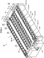
- the battery module BM includes a plurality of battery cells BC arranged in an arrangement direction ( FIG. 4 and FIG. 5 ).
- Each of the battery cells BC has two electrode terminals BC1 ( FIG. 5 ).
- Each of the electrode terminals BC1 is disposed in a state of being exposed to the outside, with one of the electrode terminals BC1 serving as a positive electrode and the other electrode terminal BC1 serving as a negative electrode.
- the housing is formed in a cuboid shape, and on one of six outer wall surfaces of the housing, each electrode terminal BC1 is arranged at intervals in an orthogonal direction with respect to the arrangement direction of each battery cell BC.
- each electrode terminal BC1 illustrated in this example is formed in a plate shape having a plane surface parallel to the outer wall surface of the housing.
- a terminal connection part 10 serving as a conductor member, which will be described below, is physically and electrically connected to one of the plane surfaces.
- the battery cells BC are arranged side by side in one direction, with one of the electrode terminals BC1 and the other electrode terminal BC1 arranged side by side in a line.
- the battery module BM there are two electrode terminal groups including the electrode terminals BC1 arranged side by side in a line ( FIG. 1 and FIG. 6).
- the term "arrangement direction" refers to the arrangement direction of the battery cells BC and the arrangement direction of the electrode terminals BC1 in each electrode terminal group.
- the battery cells BC are connected in series or parallel, when the electrode terminals BC1 are electrically connected in a predetermined combination by a terminal connection part.
- the electrode terminals BC1 that are adjacent to each other in the arrangement direction are electrically connected by the terminal connection part 10, which will be described below.
- the battery module BM illustrated in this example there are two electrode terminals BC1 that are not connected by the terminal connection part 10, and one of such electrode terminals BC1 is a total positive electrode, and the other electrode terminal BC1 is a total negative electrode.
- the battery pack BP includes at least one battery module BM.
- the conductive module 1 is assembled to the battery module BM provided in the battery pack BP, and is electrically connected to each of the battery cells BC of the battery module BM.
- the battery pack BP illustrated in this example includes two battery modules BM. Then, the two battery modules BM are arranged side by side in the arrangement direction of the positive and negative electrode terminals BC1 of the battery cells BC. Therefore, the conductive module 1 illustrated in this example is assembled to the two battery modules BM, and electrically connected to each of the battery cells BC of each of the battery modules BM.
- the conductive module 1 includes the conductor member (hereinafter referred to as the "terminal connection part") 10 to be electrically connected to the electrode terminal BC1 of each battery cell BC ( FIG. 1 to FIG. 4 ). Furthermore, the conductive module 1 includes a conductive part 20 to be mounted on the battery module BM ( FIG. 1 to FIG. 4 ). In the case where the battery pack BP includes a plurality of the battery modules BM, the conductive module 1 includes a plurality of the terminal connection parts 10 corresponding to the battery cells BC of all the battery modules BM, and includes the conductive part 20 for each of the battery modules BM.
- the conductive module 1 includes a first terminal connection part 10A that is a connection part configured to electrically connect the electrode terminals BC1 of the battery cells BC adjacent to each other in the arrangement direction, and that is provided for each combination of two adjacent electrode terminals BC1 arranged in the arrangement direction ( FIG. 1 to FIG. 4 ). Furthermore, as the terminal connection part 10, the conductive module 1 includes a second terminal connection part 10B for the total electrode ( FIG. 1 to FIG. 4 ). There are two types of the second terminal connection part 10B: one that is to be electrically connected to the electrode terminal BC1 serving as the total positive electrode, and one that is to be electrically connected to the electrode terminal BC1 serving as the total negative electrode.
- the terminal connection part 10 (10A, 10B) is formed of a conductive material such as metal.
- the terminal connection part 10 is what is called a bus bar formed of a metal plate as a base material, and the main body is formed in a substantially rectangular flat plate shape.
- the terminal connection part 10 illustrated in this example is welded (laser welded or the like) to one of the plane surfaces of the electrode terminal BC1, and thus the terminal connection part 10 is physically and electrically connected to the electrode terminal BC1.
- the first terminal connection part 10A is welded to each of the electrode terminals BC1 adjacent to each other in the arrangement direction.
- the second terminal connection part 10B is welded to one electrode terminal BC1 to be connected.
- the conductive part 20 includes a flat laminated body 30 formed of a plurality of conductors 31 and an insulator 32 having flexibility ( FIG. 2 and FIG. 3 ).
- a circuit pattern is formed by the conductors 31, and the conductors 31 are covered by the insulator 32.
- Any type of laminated body 30 may be used as long as the laminated body 30 has such a configuration.
- the laminated body 30 illustrated in this example is a flexible printed circuit board (what is called an FPC).
- the laminated body 30 has a main body 30a formed in a rectangular sheet shape, and a branch body 30b branched from the main body 30a ( FIG. 1 to FIG. 3 ).
- the main body 30a is formed in a rectangular shape in which the side parts at both ends in the arrangement direction are short sides, and the side parts at both ends in the orthogonal direction with respect to the arrangement direction are long sides.
- the conductors 31 (a first conductor 31A and a second conductor 31B, which will be described below) are covered by the insulator 32.
- the branch body 30b is provided for each first conductor 31A, which will be described below.
- the branch body 30b is branched from each of the long sides of the main body 30a.
- the first conductor 31A is covered by the insulator 32, and a part of the first conductor 31A is exposed from the insulator 32.
- the laminated body 30 includes the first conductor 31A that is configured to electrically connect the battery cells BC to a battery monitoring unit 40 ( FIG. 1 and FIG. 4 ).
- the battery monitoring unit 40 is a device for monitoring the battery status (voltage, current, temperature, and the like) of the battery cells BC.
- the battery monitoring unit 40 monitors the battery status of each battery cell BC of all the battery modules BM.
- the battery monitoring unit 40 illustrated in this example monitors the battery status of each battery cell BC of the two battery modules BM.
- the battery monitoring unit 40 illustrated in this example is assembled to the side wall of the battery module group formed of the two battery modules BM.
- the battery monitoring unit 40 is assembled to one of the side walls in the arrangement direction of the battery cells BC.
- the first conductor 31A is provided for each terminal connection part 10 in the conductive part 20.
- Each of a plurality of the first conductors 31A is formed from the main body 30a to the branch body 30b for each terminal connection part 10. Then, the first conductor 31A is physically and electrically connected to the terminal connection part 10.
- the first conductor 31A is physically and electrically connected to the terminal connection part 10, by soldering the exposed portion of the branch body 30b to the terminal connection part 10.
- the conductive part 20 includes a first connector 21 that is configured to electrically connect the first conductor 31A to the battery monitoring unit 40 ( FIG. 1 to FIG. 4 ).
- the first connector 21 is assembled to the side part of the main body 30a of the laminated body 30.
- the first connector 21 illustrated in this example is assembled to the side part, which is one of the short sides at the side where the battery monitoring unit 40 is disposed.
- the first connector 21 is fitted and connected to a counterpart connector (not illustrated) of the battery monitoring unit 40.
- This first connector 21 includes a terminal metal fitting (not illustrated) for each first conductor 31A of the laminated body 30, and the terminal metal fitting is fitted and connected to a counterpart terminal metal fitting for the first conductor 31A (not illustrated) of the counterpart connector.
- the battery monitoring unit 40 illustrated in this example includes a counterpart connector for each conductive part 20.
- the conductive module 1 includes only one conductive part 20 corresponding to the battery module BM.
- the laminated body 30 includes the second conductor 31B that is configured to electrically connect the battery monitoring unit 40 to electrical equipment 51 ( FIG. 1 ) housed in an external electrical connection box 50.
- the electrical connection box 50 houses various types of electrical equipment 51 such as an electronic control device that controls braking and driving force of a vehicle or the like, and an electrical connection member such as a bus bar (not illustrated). Then, for example, the electrical connection box 50 is fixed to the body of a vehicle or the like.
- the electrical equipment 51 serving as an electronic control device controls the driving force of a rotating machine of the vehicle, based on a detection signal of the battery status of the battery cells BC transmitted from the battery monitoring unit 40 via the second conductor 31B.
- the second conductor 31B is formed from the side part, which is one of the short sides of the main body 30a, to the side part, which is the other short side of the main body 30a.
- the laminated body 30 includes a circuit pattern layer having all the first conductors 31A, a circuit pattern layer having the second conductor 31B, an insulator layer between the two circuit pattern layers, and two insulator layers sandwiching these three layers from each circuit pattern layer side.
- the second conductor 31B is electrically connected to the battery monitoring unit 40 via the first connector 21. Therefore, the first connector 21 also includes a terminal metal fitting for the second conductor 31B (not illustrated), and the terminal metal fitting is fitted and connected to a counterpart terminal metal fitting for the second conductor 31B (not illustrated) in the counterpart connector of the battery monitoring unit 40.
- the conductive part 20 includes a second connector 22 that is configured to electrically connect the second conductor 31B to the electrical equipment 51 ( FIG. 1 , FIG. 2 , and FIG. 4 ).
- This second connector 22 is assembled to the side part of the main body 30a of the laminated body 30.
- the second connector 22 illustrated in this example is assembled to the side part, which is the other short side opposite to the side where the battery monitoring unit 40 is disposed.
- the second connector 22 is fitted and connected to the counterpart connector (not illustrated) disposed on the electrical connection box 50 side.
- the second connector 22 includes a terminal metal fitting for the second conductor 31B (not illustrated), and the terminal metal fitting is fitted and connected to the counterpart terminal metal fitting for the second conductor 31B (not illustrated) in the counterpart connector on the electrical connection box 50 side.
- the electrical connection tool 60 configured to electrically connect the conductive module 1 and the electrical equipment 51 ( FIG. 1 ).
- the electrical connection tool 60 includes an electric wire and connectors fixed to both ends of the electric wire, and one of the connectors is used as a counterpart connector on the electrical connection box 50 side, and the other connector is fitted and connected to the connector (not illustrated) of the electrical equipment 51. Consequently, the second conductor 31B is electrically connected to the electrical equipment 51.
- the conductive module 1, the electrical connection box 50, and the electrical connection tool 60 form a conductive system that detects the battery status information of the battery cells BC of the single battery module BM and that transmits the battery status information to the electrical equipment 51.
- the conductive system may also include the battery monitoring unit 40 as a component of the system.
- the conductive module 1 includes the conductive part 20 for each of the battery modules BM.
- first conductive part 20A one of a plurality of the conductive parts 20 (hereinafter referred to as a "first conductive part 20A") is configured the same as the conductive part 20 that includes the second conductor 31B and the second connector 22 as in the above-described example ( FIG. 1 and FIG. 2 ).
- the first conductive part 20A includes the first conductor 31A for each terminal connection part 10 corresponding to the battery cell BC of the battery module BM to which the first conductive part 20A is assembled, the second conductor 31B that is configured to electrically connect the battery monitoring unit 40 to the electrical equipment 51 of the electrical connection box 50, the first connector 21 that electrically connects all the first conductors 31A and the second conductor 31B to the battery monitoring unit 40, and the second connector 22 that is configured to electrically connect the second conductor 31B to the electrical equipment 51 via the electrical connection tool 60.
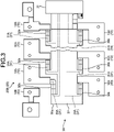
- the remaining of the conductive parts 20 includes the first conductor 31A for each terminal connection part 10 corresponding to the battery cell BC of the battery module BM to which the second conductive part 20B is assembled, and the first connector 21 that is configured to electrically connect all the first conductors 31A to the battery monitoring unit 40 ( FIG. 1 and FIG. 3 ).
- the conductive module 1, the electrical connection box 50, and the electrical connection tool 60 form a conductive system that detects the battery status information of the battery cells BC of the battery modules BM and that transmits the battery status information to the electrical equipment 51.
- the conductive system may also include the battery monitoring unit 40 as a component of the system.
- the first conductor 31A that is configured to electrically connect the battery cells BC and the battery monitoring unit 40 not only the first conductor 31A that is configured to electrically connect the battery cells BC and the battery monitoring unit 40, but also the second conductor 31B that is configured to electrically connect the battery monitoring unit 40 to the electrical equipment 51 of the electrical connection box 50 is provided as the conductor 31 of the conductive part 20 (first conductive part 20A). Then, in the conductive module 1 and the conductive system, the first conductor 31A and the second conductor 31B are electrically connected to the counterpart connector of the battery monitoring unit 40 via the first connector 21, and the second conductor 31B is electrically connected to the counterpart connector on the electrical connection box 50 side via the second connector 22.
- the conductive module 1 and the conductive system do not need to arrange a conductor such as an electric wire that is configured to electrically connect the battery monitoring unit 40 and the electrical equipment 51 of the electrical connection box 50 on a path different from that of the conductive part 20. Consequently, it is possible to reduce the size. Furthermore, because the conductive module 1 and the conductive system do not require a connector dedicated to the conductor, there is no need to prepare a counterpart connector in the battery monitoring unit 40 to fit and connect the connector. Consequently, it is also possible to reduce the size of the battery monitoring unit 40.
- the conductive module 1 and the conductive system of the present embodiment can reduce the size of the battery pack BP, by reducing the size of the conductive module 1 and the conductive system, and reducing the size of the battery monitoring unit 40. Consequently, it is possible to improve the mountability of the battery pack BP to a vehicle.
- the first conductor that is configured to electrically connect the battery cells and the battery monitoring unit is provided as the conductor of the conductive part (first conductive part). Then, in the conductive module and the conductive system, the first conductor and the second conductor are electrically connected to the counterpart connector of the battery monitoring unit via the first connector, and the second conductor is electrically connected to the counterpart connector on the electrical connection box side via the second connector.
- the conductive module and the conductive system do not need to arrange a conductor such as an electric wire that is configured to electrically connect the battery monitoring unit and the electrical equipment of the electrical connection box on a path different from that of the conductive part. Consequently, it is possible to reduce the size. Furthermore, because the conductive module and the conductive system do not require a connector dedicated to the conductor, there is no need to prepare a counterpart connector in the battery monitoring unit to fit and connect the connector. Consequently, it is also possible to reduce the size of the battery monitoring unit. Thus, the conductive module and the conductive system according to the present embodiment can reduce the size of the battery pack, by reducing the size of the conductive module and the conductive system, and reducing the size of the battery monitoring unit. Consequently, it is possible to improve the mountability of the battery pack to a vehicle.
- a conductor such as an electric wire that is configured to electrically connect the battery monitoring unit and the electrical equipment of the electrical connection box on a path different from that of the conductive part. Consequently, it is possible to reduce
Abstract
Description
- The present invention relates to a conductive module and a conductive system.
- Conventionally, in a vehicle (an electric vehicle, a hybrid vehicle, or the like) that uses a rotating machine as a driving source, a battery pack including a battery module that supplies power to the rotating machine, and a conductive module electrically connected to a plurality of battery cells that form the battery module is mounted. For example, the conductive module causes a battery monitoring unit to monitor the battery status of the battery cells, by electrically connecting the battery cells and the battery monitoring unit. For example,
Japanese Patent Application Laid-open No. 2018-26311 - In recent years, to improve the electricity consumption and to extend the cruising range of vehicles, an improvement in the energy density of a battery pack is sought after. Thus, in the battery pack, an increase in the size of the battery pack due to an increase in the energy density of battery cells has become a matter of concern, and a reduction in the size of the battery pack is also sought after to improve the mountability to a vehicle. A reduction in the size of the conductive module is also sought after without exception.
- Thus, an object of the present invention is to provide a conductive module and a conductive system capable of reducing the size.
- In order to solve the above mentioned problem and achieve the object, a conductive module according to one aspect of the present invention includes a conductive part that is a part to be mounted on a battery module in which a plurality of battery cells are arranged in an arrangement direction, and is provided with a flat laminated body formed of a plurality of conductors and an insulator having flexibility, wherein the conductive part includes a first conductor that is configured to electrically connect the battery cells to a battery monitoring unit for monitoring a battery status of the battery cells, and a second conductor that is configured to electrically connect the battery monitoring unit to electrical equipment housed in an external electrical connection box, as the conductors, and includes a first connector that is fitted and connected to a counterpart connector of the battery monitoring unit and that is configured to electrically connect the first conductor and the second conductor to the battery monitoring unit, and a second connector that is configured to be fitted and connected to a counterpart connector disposed on the electrical connection box side and is configured to electrically connect the second conductor to the electrical equipment.
- In order to achieve the object, a conductive module according to another aspect of the present invention includes a conductive part that is a part to be mounted on each battery module in which a plurality of battery cells are arranged in an arrangement direction, and is provided with a flat laminated body formed of a plurality of conductors and an insulator having flexibility, wherein the conductive part includes a first conductor that is configured to electrically connect the battery cells to a battery monitoring unit for monitoring a battery status of the battery cells as one of the conductors, and includes a first connector that is configured to be fitted and connected to a counterpart connector of the battery monitoring unit and is configured to electrically connect the first conductor to the battery monitoring unit, and one of a plurality of the conductive parts further includes a second conductor that is configured to electrically connect the battery monitoring unit to electrical equipment housed in an external electrical connection box as one of the conductors, includes a second connector that is configured to be fitted and connected to a counterpart connector disposed on the electrical connection box side and is configured to electrically connect the second conductor to the electrical equipment, and is configured to electrically connect the second conductor to the battery monitoring unit via the first connector provided in the conductive part.
- According to still another aspect of the present invention, in the conductive module, it is preferable that the conductive module includes a conductor member that is a connection part configured to electrically connect a plurality of electrode terminals of the battery cells adjacent to each other in the arrangement direction, and that is provided for each combination of two adjacent electrode terminals arranged in the arrangement direction, wherein the first conductor is provided for each conductor member.
- According to still another aspect of the present invention, in the conductive module, it is preferable that the laminated body is a flexible printed circuit board.
- In order to achieve the object, a conductive system according to still another aspect of the present invention includes a conductive module; an electrical connection box in which electrical equipment is housed; and an electrical connection tool that electrically connects the conductive module and the electrical equipment, wherein the conductive module includes a conductive part that is a part to be mounted on a battery module in which a plurality of battery cells are arranged in an arrangement direction, and is provided with a flat laminated body formed of a plurality of conductors and an insulator having flexibility, and the conductive part includes a first conductor that is configured to electrically connect the battery cells to a battery monitoring unit for monitoring a battery status of the battery cells, and a second conductor that is configured to electrically connect the battery monitoring unit to the electrical equipment via the electrical connection tool, as the conductors, and includes a first connector that is configured to be fitted and connected to a counterpart connector of the battery monitoring unit and is configured to electrically connect the first conductor and the second conductor to the battery monitoring unit, and a second connector that is configured to be fitted and connected to a counterpart connector of the electrical connection tool and is configured to electrically connect the second conductor to the electrical equipment.
- In order to achieve the object, a conductive system according to still another aspect of the present invention includes a conductive module; an electrical connection box in which electrical equipment is housed; and an electrical connection tool that electrically connects the conductive module and the electrical equipment, wherein the conductive module includes a conductive part that is a part to be mounted on each battery module in which a plurality of battery cells are arranged in an arrangement direction, and is provided with a flat laminated body formed of a plurality of conductors and an insulator having flexibility, the conductive part includes a first conductor that is configured to electrically connect the battery cells to a battery monitoring unit for monitoring a battery status of the battery cells as one of the conductors, and includes a first connector that is configured to be fitted and connected to a counterpart connector of the battery monitoring unit and is configured to electrically connect the first conductor to the battery monitoring unit, and one of a plurality of the conductive parts further includes a second conductor that is configured to electrically connect the battery monitoring unit to the electrical equipment via the electrical connection tool as one of the conductors, includes a second connector that is configured to be fitted and connected to a counterpart connector of the electrical connection tool and is configured to electrically connect the second conductor to the electrical equipment, and electrically connect the second conductor to the battery monitoring unit via the first connector provided in the conductive part.
- The above and other objects, features, advantages and technical and industrial significance of this invention will be better understood by reading the following detailed description of presently preferred embodiments of the invention, when considered in connection with the accompanying drawings.
-
-
FIG. 1 is a plan view illustrating a conductive module and a conductive system of an embodiment; -
FIG. 2 is a partially enlarged plan view of a first conductive part and the surrounding components; -
FIG. 3 is a partially enlarged plan view of a second conductive part and the surrounding components; -
FIG. 4 is a perspective view illustrating a battery pack of the embodiment; and -
FIG. 5 is a perspective view illustrating the conductive module of the embodiment. - Hereinafter, an embodiment of a conductive module and a conductive system according to the present invention will be described in detail with reference to the accompanying drawings. However, the invention is not limited to the embodiment.
- One of the embodiments of the conductive module and the conductive system according to the present invention will be described with reference to
FIG. 1 to FIG. 5 . - The
reference numeral 1 inFIG. 1 to FIG. 4 indicates a conductive module in the present embodiment. Aconductive module 1 is assembled to a battery module BM to form a battery pack BP with the battery module BM (FIG. 4 ). The battery pack BP is to be mounted on a vehicle (an electric vehicle, a hybrid vehicle, or the like) including a rotating machine as a driving source, and is used to supply power to the rotating machine and the like. - The battery module BM includes a plurality of battery cells BC arranged in an arrangement direction (
FIG. 4 andFIG. 5 ). Each of the battery cells BC has two electrode terminals BC1 (FIG. 5 ). Each of the electrode terminals BC1 is disposed in a state of being exposed to the outside, with one of the electrode terminals BC1 serving as a positive electrode and the other electrode terminal BC1 serving as a negative electrode. In the battery cell BC illustrated in this example, the housing is formed in a cuboid shape, and on one of six outer wall surfaces of the housing, each electrode terminal BC1 is arranged at intervals in an orthogonal direction with respect to the arrangement direction of each battery cell BC. Moreover, each electrode terminal BC1 illustrated in this example is formed in a plate shape having a plane surface parallel to the outer wall surface of the housing. Aterminal connection part 10 serving as a conductor member, which will be described below, is physically and electrically connected to one of the plane surfaces. - The battery cells BC are arranged side by side in one direction, with one of the electrode terminals BC1 and the other electrode terminal BC1 arranged side by side in a line. Thus, in the battery module BM, there are two electrode terminal groups including the electrode terminals BC1 arranged side by side in a line (
FIG. 1 and FIG. 6). In the following, unless otherwise specified, the term "arrangement direction" refers to the arrangement direction of the battery cells BC and the arrangement direction of the electrode terminals BC1 in each electrode terminal group. - In the battery module BM, for each electrode terminal group, the battery cells BC are connected in series or parallel, when the electrode terminals BC1 are electrically connected in a predetermined combination by a terminal connection part. In the battery module BM illustrated in this example, in each electrode terminal group, the electrode terminals BC1 that are adjacent to each other in the arrangement direction are electrically connected by the
terminal connection part 10, which will be described below. Moreover, in the battery module BM illustrated in this example, there are two electrode terminals BC1 that are not connected by theterminal connection part 10, and one of such electrode terminals BC1 is a total positive electrode, and the other electrode terminal BC1 is a total negative electrode. - The battery pack BP includes at least one battery module BM. The
conductive module 1 is assembled to the battery module BM provided in the battery pack BP, and is electrically connected to each of the battery cells BC of the battery module BM. The battery pack BP illustrated in this example includes two battery modules BM. Then, the two battery modules BM are arranged side by side in the arrangement direction of the positive and negative electrode terminals BC1 of the battery cells BC. Therefore, theconductive module 1 illustrated in this example is assembled to the two battery modules BM, and electrically connected to each of the battery cells BC of each of the battery modules BM. - First, the
conductive module 1 includes the conductor member (hereinafter referred to as the "terminal connection part") 10 to be electrically connected to the electrode terminal BC1 of each battery cell BC (FIG. 1 to FIG. 4 ). Furthermore, theconductive module 1 includes aconductive part 20 to be mounted on the battery module BM (FIG. 1 to FIG. 4 ). In the case where the battery pack BP includes a plurality of the battery modules BM, theconductive module 1 includes a plurality of theterminal connection parts 10 corresponding to the battery cells BC of all the battery modules BM, and includes theconductive part 20 for each of the battery modules BM. - As the
terminal connection part 10, theconductive module 1 includes a firstterminal connection part 10A that is a connection part configured to electrically connect the electrode terminals BC1 of the battery cells BC adjacent to each other in the arrangement direction, and that is provided for each combination of two adjacent electrode terminals BC1 arranged in the arrangement direction (FIG. 1 to FIG. 4 ). Furthermore, as theterminal connection part 10, theconductive module 1 includes a secondterminal connection part 10B for the total electrode (FIG. 1 to FIG. 4 ). There are two types of the secondterminal connection part 10B: one that is to be electrically connected to the electrode terminal BC1 serving as the total positive electrode, and one that is to be electrically connected to the electrode terminal BC1 serving as the total negative electrode. - The terminal connection part 10 (10A, 10B) is formed of a conductive material such as metal. The
terminal connection part 10 is what is called a bus bar formed of a metal plate as a base material, and the main body is formed in a substantially rectangular flat plate shape. Theterminal connection part 10 illustrated in this example is welded (laser welded or the like) to one of the plane surfaces of the electrode terminal BC1, and thus theterminal connection part 10 is physically and electrically connected to the electrode terminal BC1. For example, the firstterminal connection part 10A is welded to each of the electrode terminals BC1 adjacent to each other in the arrangement direction. On the other hand, the secondterminal connection part 10B is welded to one electrode terminal BC1 to be connected. - The
conductive part 20 includes a flat laminatedbody 30 formed of a plurality ofconductors 31 and aninsulator 32 having flexibility (FIG. 2 andFIG. 3 ). In the laminatedbody 30, a circuit pattern is formed by theconductors 31, and theconductors 31 are covered by theinsulator 32. Any type of laminatedbody 30 may be used as long as the laminatedbody 30 has such a configuration. Thelaminated body 30 illustrated in this example is a flexible printed circuit board (what is called an FPC). - The
laminated body 30 has amain body 30a formed in a rectangular sheet shape, and abranch body 30b branched from themain body 30a (FIG. 1 to FIG. 3 ). Themain body 30a is formed in a rectangular shape in which the side parts at both ends in the arrangement direction are short sides, and the side parts at both ends in the orthogonal direction with respect to the arrangement direction are long sides. In themain body 30a, the conductors 31 (afirst conductor 31A and asecond conductor 31B, which will be described below) are covered by theinsulator 32. On the other hand, thebranch body 30b is provided for eachfirst conductor 31A, which will be described below. Thebranch body 30b is branched from each of the long sides of themain body 30a. In thebranch body 30b, thefirst conductor 31A is covered by theinsulator 32, and a part of thefirst conductor 31A is exposed from theinsulator 32. - As the
conductor 31, thelaminated body 30 includes thefirst conductor 31A that is configured to electrically connect the battery cells BC to a battery monitoring unit 40 (FIG. 1 andFIG. 4 ). - The
battery monitoring unit 40 is a device for monitoring the battery status (voltage, current, temperature, and the like) of the battery cells BC. For example, in the case where the battery pack BP includes the battery modules BM, thebattery monitoring unit 40 monitors the battery status of each battery cell BC of all the battery modules BM. Thebattery monitoring unit 40 illustrated in this example monitors the battery status of each battery cell BC of the two battery modules BM. Then, thebattery monitoring unit 40 illustrated in this example is assembled to the side wall of the battery module group formed of the two battery modules BM. In this example, in the battery module group, thebattery monitoring unit 40 is assembled to one of the side walls in the arrangement direction of the battery cells BC. - For example, the
first conductor 31A is provided for eachterminal connection part 10 in theconductive part 20. Each of a plurality of thefirst conductors 31A is formed from themain body 30a to thebranch body 30b for eachterminal connection part 10. Then, thefirst conductor 31A is physically and electrically connected to theterminal connection part 10. For example, thefirst conductor 31A is physically and electrically connected to theterminal connection part 10, by soldering the exposed portion of thebranch body 30b to theterminal connection part 10. - The
conductive part 20 includes afirst connector 21 that is configured to electrically connect thefirst conductor 31A to the battery monitoring unit 40 (FIG. 1 to FIG. 4 ). Thefirst connector 21 is assembled to the side part of themain body 30a of thelaminated body 30. In themain body 30a, thefirst connector 21 illustrated in this example is assembled to the side part, which is one of the short sides at the side where thebattery monitoring unit 40 is disposed. Moreover, thefirst connector 21 is fitted and connected to a counterpart connector (not illustrated) of thebattery monitoring unit 40. Thisfirst connector 21 includes a terminal metal fitting (not illustrated) for eachfirst conductor 31A of thelaminated body 30, and the terminal metal fitting is fitted and connected to a counterpart terminal metal fitting for thefirst conductor 31A (not illustrated) of the counterpart connector. Thebattery monitoring unit 40 illustrated in this example includes a counterpart connector for eachconductive part 20. - In this example, in the case where the battery pack BP includes only one battery module BM, the
conductive module 1 includes only oneconductive part 20 corresponding to the battery module BM. In this case, as theconductor 31, thelaminated body 30 includes thesecond conductor 31B that is configured to electrically connect thebattery monitoring unit 40 to electrical equipment 51 (FIG. 1 ) housed in an externalelectrical connection box 50. - For example, the
electrical connection box 50 houses various types ofelectrical equipment 51 such as an electronic control device that controls braking and driving force of a vehicle or the like, and an electrical connection member such as a bus bar (not illustrated). Then, for example, theelectrical connection box 50 is fixed to the body of a vehicle or the like. For example, theelectrical equipment 51 serving as an electronic control device controls the driving force of a rotating machine of the vehicle, based on a detection signal of the battery status of the battery cells BC transmitted from thebattery monitoring unit 40 via thesecond conductor 31B. - The
second conductor 31B is formed from the side part, which is one of the short sides of themain body 30a, to the side part, which is the other short side of themain body 30a. For example, in this case, thelaminated body 30 includes a circuit pattern layer having all thefirst conductors 31A, a circuit pattern layer having thesecond conductor 31B, an insulator layer between the two circuit pattern layers, and two insulator layers sandwiching these three layers from each circuit pattern layer side. - The
second conductor 31B is electrically connected to thebattery monitoring unit 40 via thefirst connector 21. Therefore, thefirst connector 21 also includes a terminal metal fitting for thesecond conductor 31B (not illustrated), and the terminal metal fitting is fitted and connected to a counterpart terminal metal fitting for thesecond conductor 31B (not illustrated) in the counterpart connector of thebattery monitoring unit 40. - Furthermore, in this case, the
conductive part 20 includes asecond connector 22 that is configured to electrically connect thesecond conductor 31B to the electrical equipment 51 (FIG. 1 ,FIG. 2 , andFIG. 4 ). Thissecond connector 22 is assembled to the side part of themain body 30a of thelaminated body 30. In themain body 30a, thesecond connector 22 illustrated in this example is assembled to the side part, which is the other short side opposite to the side where thebattery monitoring unit 40 is disposed. Moreover, thesecond connector 22 is fitted and connected to the counterpart connector (not illustrated) disposed on theelectrical connection box 50 side. Thesecond connector 22 includes a terminal metal fitting for thesecond conductor 31B (not illustrated), and the terminal metal fitting is fitted and connected to the counterpart terminal metal fitting for thesecond conductor 31B (not illustrated) in the counterpart connector on theelectrical connection box 50 side. - For example, between the
conductive module 1 and theelectrical equipment 51, there is anelectrical connection tool 60 configured to electrically connect theconductive module 1 and the electrical equipment 51 (FIG. 1 ). For example, although not illustrated, theelectrical connection tool 60 includes an electric wire and connectors fixed to both ends of the electric wire, and one of the connectors is used as a counterpart connector on theelectrical connection box 50 side, and the other connector is fitted and connected to the connector (not illustrated) of theelectrical equipment 51. Consequently, thesecond conductor 31B is electrically connected to theelectrical equipment 51. - In the case where a single battery module BM as described above is provided, the
conductive module 1, theelectrical connection box 50, and theelectrical connection tool 60 form a conductive system that detects the battery status information of the battery cells BC of the single battery module BM and that transmits the battery status information to theelectrical equipment 51. The conductive system may also include thebattery monitoring unit 40 as a component of the system. - Subsequently, in the case where the battery pack BP includes a plurality of the battery modules BM, as described above, the
conductive module 1 includes theconductive part 20 for each of the battery modules BM. - In this case, one of a plurality of the conductive parts 20 (hereinafter referred to as a "first
conductive part 20A") is configured the same as theconductive part 20 that includes thesecond conductor 31B and thesecond connector 22 as in the above-described example (FIG. 1 andFIG. 2 ). In other words, the firstconductive part 20A includes thefirst conductor 31A for eachterminal connection part 10 corresponding to the battery cell BC of the battery module BM to which the firstconductive part 20A is assembled, thesecond conductor 31B that is configured to electrically connect thebattery monitoring unit 40 to theelectrical equipment 51 of theelectrical connection box 50, thefirst connector 21 that electrically connects all thefirst conductors 31A and thesecond conductor 31B to thebattery monitoring unit 40, and thesecond connector 22 that is configured to electrically connect thesecond conductor 31B to theelectrical equipment 51 via theelectrical connection tool 60. - On the other hand, the remaining of the conductive parts 20 (hereinafter referred to as a "second
conductive part 20B") includes thefirst conductor 31A for eachterminal connection part 10 corresponding to the battery cell BC of the battery module BM to which the secondconductive part 20B is assembled, and thefirst connector 21 that is configured to electrically connect all thefirst conductors 31A to the battery monitoring unit 40 (FIG. 1 andFIG. 3 ). - In the case where a plurality of the battery modules BM as described above are provided, the
conductive module 1, theelectrical connection box 50, and theelectrical connection tool 60 form a conductive system that detects the battery status information of the battery cells BC of the battery modules BM and that transmits the battery status information to theelectrical equipment 51. The conductive system may also include thebattery monitoring unit 40 as a component of the system. - As described above, in the
conductive module 1 and the conductive system of the present embodiment, not only thefirst conductor 31A that is configured to electrically connect the battery cells BC and thebattery monitoring unit 40, but also thesecond conductor 31B that is configured to electrically connect thebattery monitoring unit 40 to theelectrical equipment 51 of theelectrical connection box 50 is provided as theconductor 31 of the conductive part 20 (firstconductive part 20A). Then, in theconductive module 1 and the conductive system, thefirst conductor 31A and thesecond conductor 31B are electrically connected to the counterpart connector of thebattery monitoring unit 40 via thefirst connector 21, and thesecond conductor 31B is electrically connected to the counterpart connector on theelectrical connection box 50 side via thesecond connector 22. Thus, theconductive module 1 and the conductive system do not need to arrange a conductor such as an electric wire that is configured to electrically connect thebattery monitoring unit 40 and theelectrical equipment 51 of theelectrical connection box 50 on a path different from that of theconductive part 20. Consequently, it is possible to reduce the size. Furthermore, because theconductive module 1 and the conductive system do not require a connector dedicated to the conductor, there is no need to prepare a counterpart connector in thebattery monitoring unit 40 to fit and connect the connector. Consequently, it is also possible to reduce the size of thebattery monitoring unit 40. Thus, theconductive module 1 and the conductive system of the present embodiment can reduce the size of the battery pack BP, by reducing the size of theconductive module 1 and the conductive system, and reducing the size of thebattery monitoring unit 40. Consequently, it is possible to improve the mountability of the battery pack BP to a vehicle. - In the conductive module and the conductive system according to the present embodiment, not only the first conductor that is configured to electrically connect the battery cells and the battery monitoring unit, but also the second conductor that is configured to electrically connect the battery monitoring unit to the electrical equipment of the electrical connection box is provided as the conductor of the conductive part (first conductive part). Then, in the conductive module and the conductive system, the first conductor and the second conductor are electrically connected to the counterpart connector of the battery monitoring unit via the first connector, and the second conductor is electrically connected to the counterpart connector on the electrical connection box side via the second connector. Thus, the conductive module and the conductive system do not need to arrange a conductor such as an electric wire that is configured to electrically connect the battery monitoring unit and the electrical equipment of the electrical connection box on a path different from that of the conductive part. Consequently, it is possible to reduce the size. Furthermore, because the conductive module and the conductive system do not require a connector dedicated to the conductor, there is no need to prepare a counterpart connector in the battery monitoring unit to fit and connect the connector. Consequently, it is also possible to reduce the size of the battery monitoring unit. Thus, the conductive module and the conductive system according to the present embodiment can reduce the size of the battery pack, by reducing the size of the conductive module and the conductive system, and reducing the size of the battery monitoring unit. Consequently, it is possible to improve the mountability of the battery pack to a vehicle.
- Although the invention has been described with respect to specific embodiments for a complete and clear disclosure, the appended claims are not to be thus limited but are to be construed as embodying all modifications and alternative constructions that may occur to one skilled in the art that fairly fall within the basic teaching herein set forth.
Claims (6)
- A conductive module (1), comprising:a conductive part (20) that is a part to be mounted on a battery module (BM) in which a plurality of battery cells (BC) are arranged in an arrangement direction, and is provided with a flat laminated body (30) formed of a plurality of conductors (31) and an insulator (32) having flexibility, whereinthe conductive part (20) includes a first conductor (31A) that is configured to electrically connect the battery cells (BC) to a battery monitoring unit (40) for monitoring a battery status of the battery cells (BC), and a second conductor (31B) that is configured to electrically connect the battery monitoring unit (40) to electrical equipment (51) housed in an external electrical connection box (50), as the conductors (31), and includes a first connector (21) that is fitted and connected to a counterpart connector of the battery monitoring unit (40) and that is configured to electrically connect the first conductor (31A) and the second conductor (31B) to the battery monitoring unit (40), and a second connector (22) that is configured to be fitted and connected to a counterpart connector disposed on the electrical connection box (50) side and is configured to electrically connect the second conductor (31B) to the electrical equipment (51).
- A conductive module (1), comprising:a conductive part (20) that is a part to be mounted on each battery module (BM) in which a plurality of battery cells (BC) are arranged in an arrangement direction, and is provided with a flat laminated body (30) formed of a plurality of conductors (31) and an insulator (32) having flexibility, whereinthe conductive part (20) includes a first conductor (31A) that is configured to electrically connect the battery cells (BC) to a battery monitoring unit (40) for monitoring a battery status of the battery cells (BC) as one of the conductors (31), and includes a first connector (21) that is configured to be fitted and connected to a counterpart connector of the battery monitoring unit (40) and is configured to electrically connect the first conductor (31A) to the battery monitoring unit (40), andone of a plurality of the conductive parts (20) further includes a second conductor (31B) that is configured to electrically connect the battery monitoring unit (40) to electrical equipment (51) housed in an external electrical connection box (50) as one of the conductors (31), includes a second connector (22) that is configured to be fitted and connected to a counterpart connector disposed on the electrical connection box (50) side and is configured to electrically connect the second conductor (31B) to the electrical equipment (51), and is configured to electrically connect the second conductor (31B) to the battery monitoring unit (40) via the first connector (21) provided in the conductive part (20).
- The conductive module (1) according to claim 1 or 2, further comprising:a conductor member (10) that is a connection part configured to electrically connect a plurality of electrode terminals (BC1) of the battery cells (BC) adjacent to each other in the arrangement direction, and that is provided for each combination of two adjacent electrode terminals (BC1) arranged in the arrangement direction, whereinthe first conductor (31A) is provided for each conductor member (10).
- The conductive module (1) according to claim 1, 2, or 3, wherein
the laminated body (30) is a flexible printed circuit board. - A conductive system, comprising:a conductive module (1);an electrical connection box (50) in which electrical equipment (51) is housed; andan electrical connection tool (60) that electrically connects the conductive module (1) and the electrical equipment (51), whereinthe conductive module (1) includes a conductive part (20) that is a part to be mounted on a battery module (BM) in which a plurality of battery cells (BC) are arranged in an arrangement direction, and is provided with a flat laminated body (30) formed of a plurality of conductors (31) and an insulator (32) having flexibility, andthe conductive part (20) includes a first conductor (31A) that is configured to electrically connect the battery cells (BC) to a battery monitoring unit (40) for monitoring a battery status of the battery cells (BC), and a second conductor (31B) that is configured to electrically connect the battery monitoring unit (40) to the electrical equipment (51) via the electrical connection tool (60), as the conductors (31), and includes a first connector (21) that is configured to be fitted and connected to a counterpart connector of the battery monitoring unit (40) and is configured to electrically connect the first conductor (31A) and the second conductor (31B) to the battery monitoring unit (40), and a second connector (22) that is configured to be fitted and connected to a counterpart connector of the electrical connection tool (60) and is configured to electrically connect the second conductor (31B) to the electrical equipment (51).
- A conductive system, comprising:a conductive module (1);an electrical connection box (50) in which electrical equipment (51) is housed; andan electrical connection tool (60) that electrically connects the conductive module (1) and the electrical equipment (51), whereinthe conductive module (1) includes a conductive part (20) that is a part to be mounted on each battery module (BM) in which a plurality of battery cells (BC) are arranged in an arrangement direction, and is provided with a flat laminated body (30) formed of a plurality of conductors (31) and an insulator (32) having flexibility,the conductive part (20) includes a first conductor (31A) that is configured to electrically connect the battery cells (BC) to a battery monitoring unit (40) for monitoring a battery status of the battery cells (BC) as one of the conductors (31), and includes a first connector (21) that is configured to be fitted and connected to a counterpart connector of the battery monitoring unit (40) and is configured to electrically connect the first conductor (31A) to the battery monitoring unit (40), andone of a plurality of the conductive parts (20) further includes a second conductor (31B) that is configured to electrically connect the battery monitoring unit (40) to the electrical equipment (51) via the electrical connection tool (60) as one of the conductors (31), includes a second connector (22) that is configured to be fitted and connected to a counterpart connector of the electrical connection tool (60) and is configured to electrically connect the second conductor (31B) to the electrical equipment (51), and electrically connect the second conductor (31B) to the battery monitoring unit (40) via the first connector (21) provided in the conductive part (20).
Applications Claiming Priority (1)
| Application Number | Priority Date | Filing Date | Title |
|---|---|---|---|
| JP2021074528A JP7348227B2 (en) | 2021-04-27 | 2021-04-27 | Conductive module and conductive system |
Publications (2)
| Publication Number | Publication Date |
|---|---|
| EP4092822A1 true EP4092822A1 (en) | 2022-11-23 |
| EP4092822B1 EP4092822B1 (en) | 2024-01-24 |
Family
ID=81387035
Family Applications (1)
| Application Number | Title | Priority Date | Filing Date |
|---|---|---|---|
| EP22169993.7A Active EP4092822B1 (en) | 2021-04-27 | 2022-04-26 | Battery pack |
Country Status (4)
| Country | Link |
|---|---|
| US (1) | US20220344730A1 (en) |
| EP (1) | EP4092822B1 (en) |
| JP (1) | JP7348227B2 (en) |
| CN (1) | CN115347388A (en) |
Families Citing this family (1)
| Publication number | Priority date | Publication date | Assignee | Title |
|---|---|---|---|---|
| US20220393318A1 (en) * | 2021-06-07 | 2022-12-08 | Ford Global Technologies, Llc | Traction battery assembly having battery pack module and sense lead header and connecting method |
Citations (4)
| Publication number | Priority date | Publication date | Assignee | Title |
|---|---|---|---|---|
| US20170271642A1 (en) * | 2014-12-09 | 2017-09-21 | Elringklinger Ag | Cell contact-making system for an electrochemical device |
| JP2018026311A (en) | 2016-08-12 | 2018-02-15 | 矢崎総業株式会社 | Bus bar module and battery pack |
| US20180358820A1 (en) * | 2017-06-07 | 2018-12-13 | Denso Corporation | Monitoring device |
| EP3742523A1 (en) * | 2019-05-20 | 2020-11-25 | Yazaki Corporation | Conductive module |
Family Cites Families (5)
| Publication number | Priority date | Publication date | Assignee | Title |
|---|---|---|---|---|
| JP6291847B2 (en) | 2014-01-08 | 2018-03-14 | 株式会社デンソー | Battery cooling device |
| JP6518508B2 (en) | 2015-05-19 | 2019-05-22 | 矢崎総業株式会社 | Coated conductive member |
| JP6535309B2 (en) | 2016-09-26 | 2019-06-26 | 矢崎総業株式会社 | Battery monitoring unit |
| JP6763729B2 (en) | 2016-09-26 | 2020-09-30 | 矢崎総業株式会社 | Battery status detector |
| JP7385347B2 (en) | 2017-03-15 | 2023-11-22 | 株式会社Gsユアサ | Power storage device |
-
2021
- 2021-04-27 JP JP2021074528A patent/JP7348227B2/en active Active
-
2022
- 2022-04-14 US US17/720,314 patent/US20220344730A1/en active Pending
- 2022-04-26 EP EP22169993.7A patent/EP4092822B1/en active Active
- 2022-04-26 CN CN202210465375.XA patent/CN115347388A/en active Pending
Patent Citations (4)
| Publication number | Priority date | Publication date | Assignee | Title |
|---|---|---|---|---|
| US20170271642A1 (en) * | 2014-12-09 | 2017-09-21 | Elringklinger Ag | Cell contact-making system for an electrochemical device |
| JP2018026311A (en) | 2016-08-12 | 2018-02-15 | 矢崎総業株式会社 | Bus bar module and battery pack |
| US20180358820A1 (en) * | 2017-06-07 | 2018-12-13 | Denso Corporation | Monitoring device |
| EP3742523A1 (en) * | 2019-05-20 | 2020-11-25 | Yazaki Corporation | Conductive module |
Also Published As
| Publication number | Publication date |
|---|---|
| JP2022168869A (en) | 2022-11-09 |
| JP7348227B2 (en) | 2023-09-20 |
| EP4092822B1 (en) | 2024-01-24 |
| US20220344730A1 (en) | 2022-10-27 |
| CN115347388A (en) | 2022-11-15 |
Similar Documents
| Publication | Publication Date | Title |
|---|---|---|
| US20190245185A1 (en) | Battery wiring module | |
| CN108780860B (en) | Battery pack for vehicle and vehicle including the same | |
| US11682797B2 (en) | Systems and methods for providing individual battery cell circuit protection | |
| JP2012028186A (en) | Battery module, battery system, and electric vehicle | |
| US10244621B2 (en) | Flex circuit system for a battery assembly of an electrified vehicle | |
| JP6400808B1 (en) | Assembled battery | |
| EP4092822A1 (en) | Conductive module and conductive system | |
| US20240014517A1 (en) | Wiring module | |
| US20240014501A1 (en) | Wiring module | |
| CN112821002B (en) | Battery module and vehicle with same | |
| CN113258157A (en) | Battery and electric device | |
| EP3849006A1 (en) | Battery system with flexible printed circuit | |
| KR20230049597A (en) | Battery Sensing Structure | |
| US20230231259A1 (en) | Battery wiring module | |
| JP2019129056A (en) | Power storage module | |
| KR20200090627A (en) | Circuit carrier for battery system and battery system | |
| CN212113869U (en) | Sampling structure and battery module | |
| EP3876341A1 (en) | Conductive module | |
| US20240128614A1 (en) | Flexible wiring component | |
| KR102595716B1 (en) | Compact power relay assembly with high reliability | |
| US20240128613A1 (en) | Flexible wiring component and conductive module | |
| US20210265669A1 (en) | Serviceable flex circuit for battery module | |
| WO2024080046A1 (en) | Battery-monitoring device | |
| US20240097284A1 (en) | Battery system with flexible printed circuit | |
| US20240106083A1 (en) | Battery system with flexible printed circuit |
Legal Events
| Date | Code | Title | Description |
|---|---|---|---|
| PUAI | Public reference made under article 153(3) epc to a published international application that has entered the european phase |
Free format text: ORIGINAL CODE: 0009012 |
|
| STAA | Information on the status of an ep patent application or granted ep patent |
Free format text: STATUS: REQUEST FOR EXAMINATION WAS MADE |
|
| 17P | Request for examination filed |
Effective date: 20220426 |
|
| AK | Designated contracting states |
Kind code of ref document: A1 Designated state(s): AL AT BE BG CH CY CZ DE DK EE ES FI FR GB GR HR HU IE IS IT LI LT LU LV MC MK MT NL NO PL PT RO RS SE SI SK SM TR |
|
| STAA | Information on the status of an ep patent application or granted ep patent |
Free format text: STATUS: EXAMINATION IS IN PROGRESS |
|
| 17Q | First examination report despatched |
Effective date: 20230221 |
|
| RAP3 | Party data changed (applicant data changed or rights of an application transferred) |
Owner name: YAZAKI CORPORATION |
|
| GRAP | Despatch of communication of intention to grant a patent |
Free format text: ORIGINAL CODE: EPIDOSNIGR1 |
|
| STAA | Information on the status of an ep patent application or granted ep patent |
Free format text: STATUS: GRANT OF PATENT IS INTENDED |
|
| GRAS | Grant fee paid |
Free format text: ORIGINAL CODE: EPIDOSNIGR3 |
|
| INTG | Intention to grant announced |
Effective date: 20231120 |
|
| GRAA | (expected) grant |
Free format text: ORIGINAL CODE: 0009210 |
|
| STAA | Information on the status of an ep patent application or granted ep patent |
Free format text: STATUS: THE PATENT HAS BEEN GRANTED |
|
| AK | Designated contracting states |
Kind code of ref document: B1 Designated state(s): AL AT BE BG CH CY CZ DE DK EE ES FI FR GB GR HR HU IE IS IT LI LT LU LV MC MK MT NL NO PL PT RO RS SE SI SK SM TR |
|
| REG | Reference to a national code |
Ref country code: GB Ref legal event code: FG4D |
|
| REG | Reference to a national code |
Ref country code: CH Ref legal event code: EP |
|
| REG | Reference to a national code |
Ref country code: IE Ref legal event code: FG4D |
|
| REG | Reference to a national code |
Ref country code: DE Ref legal event code: R096 Ref document number: 602022001660 Country of ref document: DE |