EP4092804A1 - Module de batterie, bloc-batterie, appareil électrique et procédé de fabrication et dispositif de fabrication pour module de batterie - Google Patents
Module de batterie, bloc-batterie, appareil électrique et procédé de fabrication et dispositif de fabrication pour module de batterie Download PDFInfo
- Publication number
- EP4092804A1 EP4092804A1 EP21878762.0A EP21878762A EP4092804A1 EP 4092804 A1 EP4092804 A1 EP 4092804A1 EP 21878762 A EP21878762 A EP 21878762A EP 4092804 A1 EP4092804 A1 EP 4092804A1
- Authority
- EP
- European Patent Office
- Prior art keywords
- battery
- battery cells
- type
- soc
- battery cell
- Prior art date
- Legal status (The legal status is an assumption and is not a legal conclusion. Google has not performed a legal analysis and makes no representation as to the accuracy of the status listed.)
- Pending
Links
Images

Classifications
-
- H—ELECTRICITY
- H01—ELECTRIC ELEMENTS
- H01M—PROCESSES OR MEANS, e.g. BATTERIES, FOR THE DIRECT CONVERSION OF CHEMICAL ENERGY INTO ELECTRICAL ENERGY
- H01M50/00—Constructional details or processes of manufacture of the non-active parts of electrochemical cells other than fuel cells, e.g. hybrid cells
- H01M50/20—Mountings; Secondary casings or frames; Racks, modules or packs; Suspension devices; Shock absorbers; Transport or carrying devices; Holders
- H01M50/267—Mountings; Secondary casings or frames; Racks, modules or packs; Suspension devices; Shock absorbers; Transport or carrying devices; Holders having means for adapting to batteries or cells of different types or different sizes
-
- H—ELECTRICITY
- H01—ELECTRIC ELEMENTS
- H01M—PROCESSES OR MEANS, e.g. BATTERIES, FOR THE DIRECT CONVERSION OF CHEMICAL ENERGY INTO ELECTRICAL ENERGY
- H01M10/00—Secondary cells; Manufacture thereof
- H01M10/05—Accumulators with non-aqueous electrolyte
- H01M10/052—Li-accumulators
- H01M10/0525—Rocking-chair batteries, i.e. batteries with lithium insertion or intercalation in both electrodes; Lithium-ion batteries
-
- H—ELECTRICITY
- H01—ELECTRIC ELEMENTS
- H01M—PROCESSES OR MEANS, e.g. BATTERIES, FOR THE DIRECT CONVERSION OF CHEMICAL ENERGY INTO ELECTRICAL ENERGY
- H01M4/00—Electrodes
- H01M4/02—Electrodes composed of, or comprising, active material
- H01M4/36—Selection of substances as active materials, active masses, active liquids
- H01M4/362—Composites
- H01M4/366—Composites as layered products
-
- H—ELECTRICITY
- H01—ELECTRIC ELEMENTS
- H01M—PROCESSES OR MEANS, e.g. BATTERIES, FOR THE DIRECT CONVERSION OF CHEMICAL ENERGY INTO ELECTRICAL ENERGY
- H01M4/00—Electrodes
- H01M4/02—Electrodes composed of, or comprising, active material
- H01M4/36—Selection of substances as active materials, active masses, active liquids
- H01M4/48—Selection of substances as active materials, active masses, active liquids of inorganic oxides or hydroxides
- H01M4/50—Selection of substances as active materials, active masses, active liquids of inorganic oxides or hydroxides of manganese
- H01M4/505—Selection of substances as active materials, active masses, active liquids of inorganic oxides or hydroxides of manganese of mixed oxides or hydroxides containing manganese for inserting or intercalating light metals, e.g. LiMn2O4 or LiMn2OxFy
-
- H—ELECTRICITY
- H01—ELECTRIC ELEMENTS
- H01M—PROCESSES OR MEANS, e.g. BATTERIES, FOR THE DIRECT CONVERSION OF CHEMICAL ENERGY INTO ELECTRICAL ENERGY
- H01M4/00—Electrodes
- H01M4/02—Electrodes composed of, or comprising, active material
- H01M4/36—Selection of substances as active materials, active masses, active liquids
- H01M4/48—Selection of substances as active materials, active masses, active liquids of inorganic oxides or hydroxides
- H01M4/52—Selection of substances as active materials, active masses, active liquids of inorganic oxides or hydroxides of nickel, cobalt or iron
- H01M4/525—Selection of substances as active materials, active masses, active liquids of inorganic oxides or hydroxides of nickel, cobalt or iron of mixed oxides or hydroxides containing iron, cobalt or nickel for inserting or intercalating light metals, e.g. LiNiO2, LiCoO2 or LiCoOxFy
-
- H—ELECTRICITY
- H01—ELECTRIC ELEMENTS
- H01M—PROCESSES OR MEANS, e.g. BATTERIES, FOR THE DIRECT CONVERSION OF CHEMICAL ENERGY INTO ELECTRICAL ENERGY
- H01M4/00—Electrodes
- H01M4/02—Electrodes composed of, or comprising, active material
- H01M4/36—Selection of substances as active materials, active masses, active liquids
- H01M4/58—Selection of substances as active materials, active masses, active liquids of inorganic compounds other than oxides or hydroxides, e.g. sulfides, selenides, tellurides, halogenides or LiCoFy; of polyanionic structures, e.g. phosphates, silicates or borates
- H01M4/5825—Oxygenated metallic salts or polyanionic structures, e.g. borates, phosphates, silicates, olivines
-
- H—ELECTRICITY
- H01—ELECTRIC ELEMENTS
- H01M—PROCESSES OR MEANS, e.g. BATTERIES, FOR THE DIRECT CONVERSION OF CHEMICAL ENERGY INTO ELECTRICAL ENERGY
- H01M50/00—Constructional details or processes of manufacture of the non-active parts of electrochemical cells other than fuel cells, e.g. hybrid cells
- H01M50/20—Mountings; Secondary casings or frames; Racks, modules or packs; Suspension devices; Shock absorbers; Transport or carrying devices; Holders
- H01M50/204—Racks, modules or packs for multiple batteries or multiple cells
-
- H—ELECTRICITY
- H01—ELECTRIC ELEMENTS
- H01M—PROCESSES OR MEANS, e.g. BATTERIES, FOR THE DIRECT CONVERSION OF CHEMICAL ENERGY INTO ELECTRICAL ENERGY
- H01M50/00—Constructional details or processes of manufacture of the non-active parts of electrochemical cells other than fuel cells, e.g. hybrid cells
- H01M50/50—Current conducting connections for cells or batteries
- H01M50/502—Interconnectors for connecting terminals of adjacent batteries; Interconnectors for connecting cells outside a battery casing
- H01M50/509—Interconnectors for connecting terminals of adjacent batteries; Interconnectors for connecting cells outside a battery casing characterised by the type of connection, e.g. mixed connections
- H01M50/51—Connection only in series
-
- H—ELECTRICITY
- H01—ELECTRIC ELEMENTS
- H01M—PROCESSES OR MEANS, e.g. BATTERIES, FOR THE DIRECT CONVERSION OF CHEMICAL ENERGY INTO ELECTRICAL ENERGY
- H01M4/00—Electrodes
- H01M4/02—Electrodes composed of, or comprising, active material
- H01M2004/026—Electrodes composed of, or comprising, active material characterised by the polarity
- H01M2004/028—Positive electrodes
-
- Y—GENERAL TAGGING OF NEW TECHNOLOGICAL DEVELOPMENTS; GENERAL TAGGING OF CROSS-SECTIONAL TECHNOLOGIES SPANNING OVER SEVERAL SECTIONS OF THE IPC; TECHNICAL SUBJECTS COVERED BY FORMER USPC CROSS-REFERENCE ART COLLECTIONS [XRACs] AND DIGESTS
- Y02—TECHNOLOGIES OR APPLICATIONS FOR MITIGATION OR ADAPTATION AGAINST CLIMATE CHANGE
- Y02E—REDUCTION OF GREENHOUSE GAS [GHG] EMISSIONS, RELATED TO ENERGY GENERATION, TRANSMISSION OR DISTRIBUTION
- Y02E60/00—Enabling technologies; Technologies with a potential or indirect contribution to GHG emissions mitigation
- Y02E60/10—Energy storage using batteries
Definitions
- This application relates to the technical field of energy storage devices, in particular to a battery module, a battery pack, an electric apparatus, a method for manufacturing a battery module, and a device for manufacturing a battery module.
- Secondary batteries as clean and renewable resources, can be used as driving energy sources or storage units in vehicles, energy storage and other fields. With the increasing requirements for environmental protection of energy sources, the secondary batteries has become increasingly popular and widespread. In order to adapt to the needs of different environments and application scenarios, new requirements for the performance of the secondary batteries are derided in the industry.
- a plurality of battery cells of the same chemical system are usually connected in series or in parallel to form a battery module (or a battery pack).
- a battery module or a battery pack
- the battery modules (or battery packs) that use single battery cells of the same chemical system such as lithium iron phosphate battery cells or lithium nickel cobalt manganese oxide ternary battery cells, are mostly used; these battery modules or battery packs, however, are liable to be overly charged at a state of nearly fully charged during the charging process, and cause safety problems.
- one of the urgent issues in the field of second batteries is how to further prevent the overcharging and enhance the safety performance of the battery module.
- the present application is completed in view of the above problems in the prior art, and its objective is to provide a battery module, which includes a first type of battery cells and a second type of battery cells of different chemical systems, wherein the first type of battery cells and the second type of battery cells are connected at least in series.
- the second type of battery cells may accurately reflect the charge state of the battery module in a state of nearly fully charged, so as to effectively prevent the overcharge of the battery cells in the battery module and greatly improve the safety of the battery module.
- a first aspect of the present application provides a battery module, including a first type of battery cells and a second type of battery cells electrically connected at least in series, wherein the first type of battery cells and the second type of battery cells are battery cells of different chemical systems, the first type of battery cells includes N first battery cells, the second type of battery cells includes M second battery cells, and N and M are positive integers; a positive electrode plate of the second battery cell contains two or more positive electrode active materials, and when a dynamic SOC of the second battery cell is in a range from 90% to 98%, a change rate ⁇ OCV/ ⁇ SOC in an OCV relative to the SOC of the second battery cell satisfies 3 ⁇ ⁇ OCV/ ⁇ SOC ⁇ 9, in mV/%SOC, where SOC represents a charge state and OCV represents an open circuit voltage.
- the change rate ⁇ OCV/ ⁇ SOC in the OCV relative to the SOC of the second battery cell satisfies 3.5 ⁇ ⁇ OCV/ ⁇ SOC ⁇ 7, in mV/%SOC.
- the change rate ⁇ OCV/ ⁇ SOC in the OCV relative to the SOC of the second battery cell satisfies ⁇ OCV/ ⁇ SOC ⁇ 1, in mV/%SOC.
- the change rate ⁇ OCV/ ⁇ SOC in the OCV relative to the SOC of the second battery cell satisfies ⁇ OCV/ ⁇ SOC ⁇ 0.25, in mV/%SOC.
- a discharge battery balance rate CB2 of the second battery cell is 1.00 ⁇ CB2 ⁇ 1.16, and optionally is 1.03 ⁇ CB2 ⁇ 1.11.
- a positive electrode active material of the second battery cell includes at least a layered lithium transition metal oxide represented by formula (I) and a lithium-containing phosphate represented by formula (II), Li 1 + x1 Ni a1 CO b1 M1 c1 M2 1-a1-b1-c1 O 2-y ,Al y1 formula (I) LiFe 1-x2-y2 Mn x2 M' y2 PO 4 formula (II) in formula (I), -0.1 ⁇ x1 ⁇ 0.2, 0.3 ⁇ a1 ⁇ 0.97, 0 ⁇ b1 ⁇ 0.3, 0 ⁇ a1 + b1 + c1 ⁇ 1, 0 ⁇ y1 ⁇ 0.2, M1 is at least one selected from Mn and Al, M2 is one or more selected from Fe, Cr, Ti, Zn, V, Al, W, Mg, B, Cu, Y, Si, Sr, Zr and Ce, and A1 is one or
- the layered lithium transition metal oxide represented by formula (I) has a mass percentage from 0.5 wt% to 30 wt%, optionally from 1 wt% to 20 wt%, and further optionally from 3 wt% to 15 wt%.
- the first battery cell satisfies the following conditions 1 and 2,
- a discharge battery balance rate CB1 of the first battery cell satisfies 1.00 ⁇ CB1 ⁇ 1.18; and optionally, 1.04 ⁇ CB1 ⁇ 1.14.
- a positive electrode active material of the first battery cell includes a lithium-containing phosphate represented by formula (III), LiFe 1-x3-y3 Mn x3 M" y3 PO 4 formula (III) where 0 ⁇ x3 ⁇ 1, 0 ⁇ y3 ⁇ 0.1, and M" is one or more selected from transition metal elements and non-transition metal elements other than Fe and Mn.
- formula (III) LiFe 1-x3-y3 Mn x3 M" y3 PO 4 formula (III) where 0 ⁇ x3 ⁇ 1, 0 ⁇ y3 ⁇ 0.1, and M" is one or more selected from transition metal elements and non-transition metal elements other than Fe and Mn.
- the positive electrode active material of the first battery cell includes one or more of LiFePO 4 , LiMnPO 4 , LiMn 1-x3 Fe x3 PO 4 , and LiV 1-x3 FeX 3 PO 4 , where x3 independently satisfies 0 ⁇ x3 ⁇ 1.
- the positive electrode active material for the first battery cell includes at least a layered lithium transition metal oxide represented by formula (IIII), Li 1+x4 Ni a2 Co b2 M3 c2 M4 1-a2-b2-c2 O 2-y4 A2 y4 formula (IIII) in formula (IIII),-0.1 ⁇ x4 ⁇ 0.2, 0.3 ⁇ a2 ⁇ 0.95, 0 ⁇ b2 ⁇ 0.3, 0 ⁇ a2 + b2 + c2 ⁇ 1, 0 ⁇ y4 ⁇ 0.2, M3 is at least one selected from Mn and Al, M4 is one or more selected from Fe, Cr, Ti, Zn, V, Al, Zr and Ce, and A2 is one or more selected from S, F, Cl and I.
- formula (IIII) Li 1+x4 Ni a2 Co b2 M3 c2 M4 1-a2-b2-c2 O 2-y4 A2 y4 formula (IIII) in formula (IIII),-0.1
- a second aspect of the present application provides a battery pack, including the battery module according to the first aspect.
- a third aspect of the present application provides an electric apparatus, including the battery module according to the first aspect or the battery pack according to the second aspect, wherein the battery module or the battery pack is used as a power source or an energy storage unit of the electric apparatus.
- a fourth aspect of the present application provides a method for manufacturing a battery module, including the following steps: obtaining a first type of battery cells and a second type of battery cells, wherein the first type of battery cells and the second type of battery cells are battery cells of different chemical systems, the first type of battery cells includes N first battery cells, the second type of battery cells includes M second battery cells, N and M are positive integers, a positive electrode plate of the second battery cell contains two or more positive electrode active materials, and when a dynamic SOC of the second battery cell is in a range from 90% to 98%, a change rate ⁇ OCV/ ⁇ SOC in an OCV relative to the SOC of the second battery cell satisfies 3 ⁇ ⁇ OCV/ ⁇ SOC ⁇ 9, where SOC represents a charge state and OCV represents an open circuit voltage; and connecting the first type of battery cells and the second type of battery cells at least in series to form the battery module according to the first aspect.
- a fifth aspect of the present application provides a device for manufacturing a battery module, including: a clamping arm unit, which is used to obtain a first type of battery cells and a second type of battery cells, the first type of battery cells and the second type of battery cells are battery cells of different chemical systems, the first type of battery cells includes N first battery cells, the second type of battery cells includes M second battery cells, N and M are positive integers, a positive electrode plate of the second battery cell contains two or more positive electrode active materials, and when a dynamic SOC of the second battery cell is in a range from 90% to 98%, a change rate ⁇ OCV/ ⁇ SOC in an OCV relative to the SOC of the second battery cell satisfies 3 ⁇ ⁇ OCV/ ⁇ SOC ⁇ 9, where SOC represents a charge state and OCV represents an open circuit voltage; an assembling unit, which is used to connect the first type of battery cells and the second type of battery cells at least in series to form the battery module according to the first aspect; and a control unit, which is used to control
- the present application provides a battery module, which includes a first type of battery cells and a second type of battery cells of different chemical systems, wherein the first type of battery cells and the second type of battery cells are electrically connected in series at least, and SOC-OCV curves of the first type of battery cells and that of the second type of battery cells are matched.
- the second type of battery cells may accurately reflect the charge state of the battery module, so as to effectively prevent the overcharge of the battery module and greatly improve the safety of the battery module.
- range is defined by a lower limit and an upper limit.
- a given range is defined by selecting a lower limit and an upper limit, and the selected lower limit and upper limit define the boundaries of a particular range.
- the range defined in this way can include or exclude end values, and can be combined arbitrarily, that is, any lower limit can be combined with any upper limit to form a range.
- a range of 60-120 and 80-110 is listed for a specific parameter, it is understood that a range of 60-110 and 80-120 is are also expected.
- minimum values of a range 1 and 2 are listed and maximum values of a range 3, 4 and 5 are listed, the following ranges can all be expected: 1-3, 1-4, 1-5, 2-3, 2-4 and 2-5.
- the numerical range "a-b” represents an abbreviation of any combination of real numbers between a and b, where both a and b are real numbers.
- the numerical range "0-5" represents all real numbers “0-5" listed herein, and "0-5" is only an abbreviation of a combination of these values.
- a parameter is expressed as an integer ⁇ 2, it is equivalent to disclosing that the parameter is, for example, an integer 2, 3, 4, 5, 6, 7, 8, 9, 10, 11, 12, etc.
- the method includes steps (a) and (b), which represents that the method may include steps (a) and (b) performed sequentially, or may include steps (b) and (a) performed sequentially.
- the method may further include step (c), which represents that step (c) may be added to the method in any order, for example, the method may include steps (a), (b) and (c), or steps (a), (c) and (b), or steps (c), (a) and (b).
- the term "or” is inclusive.
- the phrase “A or B” means “A, B, or both A and B”. More specifically, any of the following conditions satisfies the condition "A or B”: A is true (or exists) and B is false (or does not exist); A is false (or does not exist) and B is true (or exists); or both A and B are true (or exist).
- the “battery cell” refers to a battery unit that can be independently charged and discharged.
- the battery cell includes a positive electrode plate, a negative electrode plate, a separator, an electrolyte solution, and an outer package for packaging the positive electrode plate, the negative electrode plate, the separator and the electrolyte solution.
- the type and shape of the battery cell are not particularly limited in the present application, and the battery cell may be various types of battery cells, such as a soft-packed battery cell, a cylindrical battery cell, or a square battery cell.
- the battery cell in the present application may be a lithium ion battery cell, a potassium ion battery cell, a sodium ion battery cell, a lithium sulfur battery cell, etc., and the lithium ion battery cell is particularly preferred.
- active ions are repeatedly intercalated and deintercalated between the positive electrode plate and the negative electrode plate.
- the electrolyte conducts the ions between the positive electrode plate and the negative electrode plate.
- the “battery cell” refers to a battery unit that can be independently charged and discharged.
- the components of the battery cell may include a positive electrode plate, a negative electrode plate, a separator, an electrolyte solution, and an outer package for packaging the positive electrode plate, the negative electrode plate, the separator and the electrolyte solution.
- the type and shape of the battery cell are not particularly limited in the present application, and the battery cell may be various types of battery cells, such as a soft-packed battery cell, a cylindrical battery cell, or a square battery cell.
- the battery cell in the present application may be a lithium ion battery cell, a potassium ion battery cell, a sodium ion battery cell, a lithium sulfur battery cell, etc., and the lithium ion battery cell is particularly preferred.
- active ions are repeatedly intercalated and deintercalated between the positive electrode plate and the negative electrode plate.
- the electrolyte conducts ions between the positive electrode plate and the negative electrode plate.
- the "chemical system" of the battery cell is classified according to the components of a positive electrode active material used in the positive electrode plate of the battery cell, and the elements or substances that are doped in or is used to coat the positive electrode active material are not limited.
- the battery cell which positive electrode active material is lithium iron phosphate (including those doped with Mn or V elements) may be defined as a battery cell of a lithium iron phosphate chemical system.
- the battery cell which positive electrode active material is lithium nickel cobalt manganate (generally referred to as NCM) may be defined as a battery cell a NCM chemical system.
- the chemical system of the battery cell may be further limited based on the relative content of nickel, cobalt, and manganese in the positive electrode active material.
- the battery cell which positive electrode active material is LiNi 0.5 Co 0.2 Mn 0.3 O 2 may be defined as a battery cell of a NCM523 chemical system
- the battery cell which positive electrode active material is LiNi 0.6 Co 0.2 Mn 0.2 O 2 (generally referred to as NCM622) may be defined as a battery cell of a NCM622 chemical system
- the battery cell which positive electrode active material is LiNi 0.8 Co 0.1 Mn 0.1 O 2 (generally referred to as NCM811) may be defined as a battery cell of a NCM811 chemical system.
- the battery cell using nickel cobalt lithium aluminate system (generally referred to as NCA) as a positive electrode material may be defined as a battery cell of a NCA chemical system.
- NCA nickel cobalt lithium aluminate system
- a battery cell of a hybrid system may also be used, for example, a battery cell of a hybrid system including NCM and NCA.
- the positive electrode plate includes a positive electrode current collector and a positive electrode film disposed on at least one surface of the positive electrode current collector and including a positive electrode active material.
- the positive electrode current collector has two opposite surfaces in its thickness direction, and the positive electrode film is disposed on either or both of the two opposite surfaces of the positive electrode current collector.
- the positive electrode current collector may be a metal foil or a composite current collector.
- the metal foil may be an aluminum foil
- the composite current collector may include a polymer material base layer and a metal layer formed on at least one surface of the polymer material base layer.
- the composite current collector may be formed by forming a metal material (aluminum, aluminum alloy, nickel, nickel alloy, titanium, titanium alloy, silver and silver alloy) on a polymer material substrate (such as substrates of polypropylene (PP), polyethylene terephthalate (PET), polybutylene terephthalate (PBT), polystyrene (PS), polyethylene (PE) and copolymers thereof).
- a metal material aluminum alloy, nickel, nickel alloy, titanium, titanium alloy, silver and silver alloy
- a polymer material substrate such as substrates of polypropylene (PP), polyethylene terephthalate (PET), polybutylene terephthalate (PBT), polystyrene (PS), polyethylene (PE) and copolymers thereof.
- the positive electrode active material may be a positive electrode active material for a battery cell known in the art.
- the positive electrode active material may include one or more of the following: an olivine structured lithium-containing phosphate, a lithium transition metal oxide, and the modified compounds thereof.
- the present application is not limited to these materials, and other traditional materials that can be used as positive electrode active materials for battery cells can also be used. These positive electrode active materials may be used alone, or two or more of them may be used together.
- lithium transition metal oxide may include, but are not limited to, one or more of a lithium cobalt oxide (such as LiCoO 2 ), a lithium nickel oxide (such as LiNiO 2 ), a lithium manganese oxide (such as LiMnO 2 and LiMn2O 4 ), a lithium nickel cobalt oxide, a lithium manganese cobalt oxide, a lithium nickel manganese oxide, a lithium nickel cobalt manganese oxide (such as LiNi 1/3 Co 1/3 Mn 1/3 O 2 (NCM333), LiNi 0.5 CO 0.2 Mn 0.3 O 2 (NCM523), LiNi 0.5 Co 0.25 Mn 0.25 O 2 (NCM211), LiNi 0.6 Co 0.2 Mn 0.2 O 2 (NCM622), and LiNi 0.8 Co 0.1 Mn 0.1 O 2 (NCM811)), a lithium nickel cobalt aluminum oxide (such as LiNi 0.85 Co 0.15 Al 0.05 O 2 ), and the modified compounds thereof.
- a lithium cobalt oxide such
- Examples of the olivine structured lithium-containing phosphate may include, but are not limited to, one or more of a lithium iron phosphate (such as LiFePO 4 (LFP)), a composite material of lithium iron phosphate and carbon, a lithium manganese phosphate (such as LiMnPO 4 ), a composite material of lithium manganese phosphate and carbon, a lithium iron manganese phosphate, and a composite material of lithium iron manganese phosphate and carbon.
- a lithium iron phosphate such as LiFePO 4 (LFP)
- LiMnPO 4 lithium manganese phosphate
- the positive electrode film may further optionally include a binder.
- the binder that can be used in the positive electrode film may include one or more of the following: polyvinylidene fluoride (PVDF), polytetrafluoroethylene (PTFE), vinylidene fluoride-tetrafluoroethylene-propylene copolymer, vinylidene fluoride-hexafluoropropylene-tetrafluoroethylene terpolymer, tetrafluoroethylene-hexafluoropropylene copolymer and fluorinated acrylate resin.
- PVDF polyvinylidene fluoride
- PTFE polytetrafluoroethylene
- PTFE polytetrafluoroethylene
- terpolymer vinylidene fluoride-hexafluoropropylene-tetrafluoroethylene terpolymer
- tetrafluoroethylene-hexafluoropropylene copolymer and fluorin
- the positive electrode film may further optionally include a conductive agent.
- the conductive agent used in the positive electrode film may include one or more of superconducting carbon, acetylene black, carbon black, Ketjen black, carbon dots, carbon nanotubes, graphene, and carbon nanofibers.
- a positive electrode can be prepared by the following way: the above-mentioned components for preparing the positive electrode, such as the positive electrode active material, the conductive agent, the binder, and any other components, are dissolved in a solvent (such as N-methylpyrrolidone) to form a uniform positive electrode slurry; and the positive electrode slurry is coated on the positive electrode current collector, after steps of drying, cold pressing, etc, a positive electrode plate may be obtained.
- a solvent such as N-methylpyrrolidone
- the battery cell of the present application includes a negative electrode plate, wherein the negative electrode plate includes a negative electrode current collector and a negative electrode film disposed on at least one surface of the negative electrode current collector, and the negative electrode film includes a negative electrode active material.
- the negative electrode active material in the negative electrode film may be a negative electrode active material commonly used in the art, such as one or more of natural graphite, artificial graphite, soft carbon, hard carbon, a silicon-based material, a tin-based material, and lithium titanate.
- the silicon-based material may be one or more selected from elemental silicon, a silicon oxide, and a silicon-carbon composite.
- the tin-based material may be one or more selected from elemental tin, a tin oxide, and a tin alloy.
- the negative electrode film may further include an optional binder, an optional conductive agent, and optional other additives.
- the negative electrode film of the present application is usually formed by coating and drying a negative electrode slurry.
- the negative electrode slurry is usually formed by dispersing the negative electrode active material and the optional conductive agent and binder in a solvent and stirring the same uniformly.
- the solvent may be N-methylpyrrolidone (NMP) or deionized water.
- the conductive agent may include one or more of superconducting carbon, carbon black (such as acetylene black, or Ketjen black), carbon dots, carbon nanotubes, graphene and carbon nanofibers.
- carbon black such as acetylene black, or Ketjen black
- carbon dots carbon nanotubes, graphene and carbon nanofibers.
- the binder may include one or more of styrene butadiene rubber (SBR), water-soluble unsaturated resin SR-1B, polyacrylic acid (PAA), polyacrylic acid sodium (PAAS), polyacrylamide (PAM), polyvinyl alcohol (PVA), sodium alginate (SA) and carboxymethyl chitosan (CMCS).
- the binder may include one or more of styrene-butadiene rubber (SBR), polyvinyl alcohol (PVA), sodium alginate (SA), polymethacrylic acid (PMAA) and carboxymethyl chitosan (CMCS).
- the optional other additives are, for example, a thickener (such as sodium carboxymethyl cellulose CMC-Na), a PTC thermistor material, etc.
- the negative electrode plate does not exclude other additional functional layers other than the negative electrode film.
- the negative electrode plate of the present application may further include a conductive undercoating (for example, comprising a conductive agent and a binder) sandwiched between the negative electrode current collector and a first negative electrode film and disposed on the surface of the negative electrode current collector.
- the negative electrode plate of the present application may further include a covering protective layer covering the surface of a second negative electrode film.
- the negative electrode current collector may be a metal foil or a composite current collector.
- the metal foil may be a copper foil, a silver foil, an iron foil, or a foil composed of an alloy of the foregoing metals.
- the composite current collector may include a polymer material base layer and a metal layer formed on at least one surface of the polymer material base layer, and may be formed by forming the metal material (copper, copper alloy, nickel, nickel alloy, titanium, titanium alloy, silver and silver alloy, etc.) on the polymer material base layer (such as a base layer prepared from polypropylene (PP), polyethylene terephthalate (PET), polybutylene terephthalate (PBT), polystyrene (PS), polyethylene (PE) and copolymers thereof).
- PP polypropylene
- PET polyethylene terephthalate
- PBT polybutylene terephthalate
- PS polystyrene
- PE polyethylene
- the electrolyte solution conducts ions between the positive electrode plate and the negative electrode plate.
- the electrolyte solution includes an electrolyte salt and a solvent.
- the electrolyte salt may be one or more selected from lithium hexafluorophosphate (LiPF 6 ), lithium tetrafluoroborate (LiBF 4 ), lithium perchlorate (LiClO 4 ), lithium hexafluoroarsenate (LiAsF 6 ), lithium bisfluorosulfonimide (LiFSI) , lithium bistrifluoromethanesulfonimide (LiTFSI), lithium trifluoromethanesulfonate (LiTFS), lithium difluorooxalate (LiDFOB), lithium bisoxalate (LiBOB), lithium difluorophosphate (LiPO 2 F 2 ), lithium difluorobisoxalate phosphate (LiDFOP) and lithium tetrafluorooxa
- the solvent may be one or more selected from the following: ethylene carbonate (EC), propylene carbonate (PC), ethyl methyl carbonate (EMC), diethyl carbonate (DEC), dimethyl carbonate (DMC), dipropyl carbonate (DPC), methyl propyl carbonate (MPC), ethylene propyl carbonate (EPC), butylene carbonate (BC), fluoroethylene carbonate (FEC), methyl formate (MF), methyl acetate (MA), ethyl acetate (EA), propyl acetate (PA), methyl propionate (MP), ethyl propionate (EP), propyl propionate (PP), methyl butyrate (MB), ethyl butyrate (EB), 1,4-butyrolactone (GBL), sulfolane (SF), dimethyl sulfone (MSM), ethyl methyl sulfone (EMS), and ethylsulf
- EC ethylene carbon
- the content of the solvent is 60-99 wt%, such as 65-95 wt%, or 70-90 wt%, or 75-89 wt%, or 80-85 wt%. In one embodiment of the present application, based on a total weight of the electrolyte solution, the content of the electrolyte is 1-40 wt%, such as 5-35 wt%, or 10-30 wt%, or 11-25 wt%, or 15-20 wt%.
- the electrolyte solution may further optionally include an additive.
- the additive may include one or more of the following: a negative electrode film-forming additive, a positive electrode film-forming additive, and an additive that can improve certain performance of the battery, such as an additive that improves the overcharge performance of the battery, an additive that improves the high-temperature performance of the battery, and an additive that improves the low-temperature performance of the battery.
- the battery cell further includes a separator, wherein the separator separates the positive electrode plate from the negative electrode plate of the battery cell and provides selective permeation or blocking of materials of different types, sizes, and charges in the system, for example, the separator can insulate electrons, physically isolate the positive and negative electrode active materials of the battery cell to prevent internal short circuits and formation of an electric field in a certain direction, and enable the ions in the battery to pass through the separator and move between the positive and negative electrodes.
- the separator separates the positive electrode plate from the negative electrode plate of the battery cell and provides selective permeation or blocking of materials of different types, sizes, and charges in the system, for example, the separator can insulate electrons, physically isolate the positive and negative electrode active materials of the battery cell to prevent internal short circuits and formation of an electric field in a certain direction, and enable the ions in the battery to pass through the separator and move between the positive and negative electrodes.
- the material used to prepare the separator may include one or more of glass fibers, a non-woven fabric, polyethylene, polypropylene and polyvinylidene fluoride.
- the separator may be a single-layer film or a multi-layer composite film. When the separator is a multi-layer composite film, the materials of each layer may be the same or different.
- the above-mentioned positive electrode plate, negative electrode plate and separator can be made into an electrode assembly/bare cell through a winding process or a lamination process.
- the battery cell further includes an outer package, wherein the outer package can be used to package the above-mentioned electrode assembly and electrolyte solution.
- the outer package of the battery cell may be a hard case, such as a hard plastic case, an aluminum case, or a steel case.
- the outer package of the battery cell may be a soft bag, such as a pocket type soft bag.
- the material of the soft bag may be plastic, such as one or more of polypropylene (PP), polybutylene terephthalate (PBT), and polybutylene succinate (PBS).
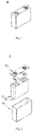
- Fig. 1 is a schematic diagram showing an example of a battery cell 5 of the present application.
- Fig. 2 is an exploded view showing an example of the battery cell 5 of the present application shown in Fig. 1 .
- the outer package may include a shell 51 and a cover plate 53, wherein the shell 51 may include a bottom plate and side plates connected to the bottom plate, and the bottom plate and the side plates enclose to form a receiving cavity.
- the shell 51 has an opening communicated with the receiving cavity, and the cover plate 53 can cover the opening to close the receiving cavity.
- the positive electrode plate, the negative electrode plate and the separator can form an electrode assembly 52 through a winding process or a lamination process, wherein the electrode assembly is packaged in the receiving cavity, and the electrolyte solution infiltrates the electrode assembly 52.
- the number of electrode assemblies 52 included in the battery cell 5 may be one or more.
- the “battery module” is formed by electrically connecting a certain number of battery cells together and putting them into a frame in order to protect the battery cells from external impact, heat, vibration, etc.
- the shape of the battery cell of the present application may be cylindrical, square, or in other arbitrary shapes.
- a number of battery cells may be assembled together to form a battery module, the battery module includes two or more battery cells, and the specific number depends on the application of the battery module and the parameters of a single battery module.
- Fig. 3 is a schematic diagram showing an example of a battery module of the present application.
- a plurality of battery cells 5a and 5b may be arranged sequentially in the length direction of the battery module 4 (wherein 5a may be first battery cells, and 5b may be second battery cells).
- the battery cells may also be arranged in any other way.
- the plurality of battery cells 5a and 5b can be fixed by fasteners.
- the battery module 4 may further include a housing having a receiving space, and the plurality of battery cells 5a and 5b are received in the receiving space.
- the battery module includes a first type of battery cells and a second type of battery cells connected at least in series, wherein the first type of battery cells and the second type of battery cells are battery cells of different chemical system,
- the capacity of a battery is generally reflected by the charge state (SOC) of the battery as tested.
- a battery module uniformly output electrical energy to the outside througha plurality of battery cells of the same chemical system are connected in series/parallel.
- the same chemical system of the multiple battery cells in the battery module has the advantages of helping to improve the consistency of charging and discharging of the multiple battery cells, avoiding the cask effect, and helping to improve the overall electrical performance and service life of the battery module.
- Common positive electrode active materials include olivine-structure materials such as lithium iron phosphate, and ternary layered materials such as lithium nickel cobalt manganese oxide.
- the positive electrode active material of the battery cell in the battery module is a material with a long charging platform, such as lithium iron phosphate, at the state that the battery cell is nearly fully charged (that is, in the range of 90% to 100% SOC), the OCV increases sharply with the increasing of SOC of the battery cell, as a result the SOC, when the battery cell is nearly fully charged, cannot be accurately determined by the OCV, an overcharging of the battery module occurs easily. Meanwhile, in order to increase the energy density of the battery module, the amount of the negative electrode active material is usually reduced as much as possible. As a result, when the battery cell is nearly fully charged, the active sites of the negative electrode plate for the intercalation of lithium ions drastically reduce, an overcharging causes easily. Therefore, on the premise of ensuring good electrical performance of the battery module, the technical problem to be urgently solved currently is how to further solve the overcharging problem of the battery module and to improve the safety of the battery module.
- a material with a long charging platform such as lithium iron phosphate
- the present application provides a battery module, which includes a first type of battery cells and a second type of battery cells of different chemical systems, wherein the first type of battery cells and the second type of battery cells are connected at least in series, and a positive electrode active material in the second type of battery cells is a composite material, so that an OCV change rate of the second type of battery cells at a high SOC state is in a range from 3 to 9 mV/%SOC. Since the first type of battery cells and the second type of battery cells in the battery module are connected at least in series, the charging and discharging trends of the two types of battery cells are identical.
- the characteristic of second type of battery cells can be identified easily and accurately by means of the change of the open circuit voltage at the high SOC state. Therefore, the change of the charge state of the second type of battery cells may be used to characterize the change of the overall charge state of the battery module.
- the battery module formed as above may, on the premise of ensuring stable output of basic electrical performance of, effectively solve the problem of the overcharging of the battery module, and improve the safety of the battery module.
- the method of obtaining a dynamic OCV change curve of the battery cell in any range from 0% to 100% SOC generally includes the following steps:
- the test rates in steps 1) to 5) of the dynamic battery SOC test method may also be any value from 0.01 C to 0.5 C.
- the nominal current can be freely selected according to the capacity of the battery module. For example, when the capacity of the battery module is 50 Ah, the nominal current may be 50 A. For another example, when the capacity of the battery module is 100 Ah, the nominal current may be 100 A.
- the charge termination voltage and the discharge termination voltage can be determined by referring to the provisions in the technical specification of the product or the GBT certification documents for battery cells/battery modules.
- the OCV change difference corresponding to any SOC range can be obtained, and the OCV change rate ( ⁇ OCV/ ⁇ SOC) of the battery cell in certain SOC range can obtained by division.
- the change rate ⁇ OCV/ ⁇ SOC in the OCV relative to the SOC of the second battery cell satisfies 3.5 ⁇ ⁇ OCV/ ⁇ SOC ⁇ 7, in mV/%SOC. That is, at high SOC range, for every 1% increase or decrease in the charge state of the second battery cell, the open circuit voltage of the second battery cell will increase or decrease by at least 3.5-7 mV, which value can satisfy the identification accuracy of a BMS, so as to obtain the accurate change in the charge state when the entire battery module is immediately fully charged.
- the change rate ⁇ OCV/ ⁇ SOC in the OCV relative to the SOC of the second battery cell satisfies ⁇ OCV/ ⁇ SOC ⁇ 1, in mV/%SOC.
- the change rate ⁇ OCV/ ⁇ SOC in the OCV relative to the SOC of the second battery cell satisfies ⁇ OCV/ ⁇ SOC ⁇ 0.25, in mV/%SOC.
- the second battery cell has relatively low the OCV change rate when SOC is in the range from 30% to 80%, so that the second battery cell can maintain a relatively long and stable charging voltage platform during the charging and discharging process. This ensures small structure and chemical changes of the positive electrode active material during repeated charging and discharging and less decay of the charging and discharging capacity with long-term use. As a result, it is beneficial to prolong the cycle life of the entire battery module.
- the discharge battery balance rate CB2 of the second battery cell satisfies 1.00 ⁇ CB2 ⁇ 1.16.
- the utilization of the positive and negative electrode active materials in the second battery cell can be further improved, the volumetric energy density of single second battery cell is improved, and relatively low risk of lithium evolution in the second battery cell is ensured simultaneously.
- the discharge battery balance rate of a battery cell has a well-known meaning in the art, and can be tested by conventional methods.
- the discharge capacity of the positive electrode plate or the negative electrode plate has a well-known meaning in the art, and can be tested by conventional methods.
- the discharge capacity can be tested by the following steps:
- the positive electrode active material of the second battery cell includes at least a layered lithium transition metal oxide represented by formula (I) and a lithium-containing phosphate represented by formula (II), Li 1+x1 Ni a1 Co b1 M 1-a1-b1 O 2-y1 A y1 formula (I) LiFe 1-x2-y2 Mn x2 M' y2 PO 4 formula (II) in formula (I), -0.1 ⁇ x1 ⁇ 0.2, 0.3 ⁇ a1 ⁇ 0.95, 0 ⁇ b1 ⁇ 0.2, 0 ⁇ a1 + b1 ⁇ 1, 0 ⁇ y1 ⁇ 0.2, M is one or more selected from Mn, Fe, Cr, Ti, Zn, V, Al, Zr and Ce, and A is one or more selected from S, F, Cl and I; and in formula (II), 0 ⁇ x2 ⁇ 1, 0 ⁇ y2 ⁇ 0.1, and M' is one
- the change rate ⁇ OCV/ ⁇ SOC in the OCV relative to the SOC satisfies ⁇ OCV/ ⁇ SOC ⁇ 1 when the SOC of the second battery cell during the charging process is in the range from 30% to 80%
- the change rate ⁇ OCV/ ⁇ SOC in the OCV relative to the SOC satisfies 3 ⁇ ⁇ OCV/ ⁇ SOC ⁇ 9 when the SOC is in the range from 90% to 98%.
- the change rate in OCV and SOC of the second battery cell is still within an appropriate range at the state that the second battery cell is immediately fully charged, it is beneficial for the BMS to accurately obtain the charge state of the battery cells in series in the battery module, so as to realize good capability of preventing overcharge of the battery module.
- the positive electrode active material in the second type of battery cells is a mixture of compounds of formula (I) and formula (II).
- the initial coulombic efficiency of the compound of formula (I) is lower than that of the compound of formula (II), and the charge and discharge platform of the compound of formula (II) is longer, so active ions deintercalated from the compound of formula (I) with lower first coulombic efficiency can be stored in the negative electrode plate, and can continue to participate in the electrochemical reaction in the later stage of use of the battery cell, so as to supplement the capacity loss caused by the consumption of active ions and further prolong the cycle life of the battery module.
- the layered lithium transition metal oxide represented by formula (I) has a mass percentage from 0.5 wt% to 25 wt%, optionally from 1 wt% to 20 wt%, and further optionally from 3 wt% to 15 wt%.
- the first battery cell satisfies condition 1 and condition 2,
- the change in the overall charge state of the battery module can be accurately characterized by the characteristic that the OCV change of the second type of battery cells in the high SOC is identified easily and accurately, which effectively solves the problem of overcharge of the battery module; meanwhile, a relatively small difference in charge and discharge performance of the first type of battery cells and the second type of battery cells can also be ensured, which helps to improve the overall electrical performance output effect of the battery module.
- the discharge battery balance rate CB1 of the first battery cell satisfies 1.00 ⁇ CB1 ⁇ 1.18; and optionally, 1.04 ⁇ CB1 ⁇ 1.14.
- the discharge battery balance rate of the first battery cell is relatively small, such type of battery cells, at the sated of being nearly fully charged, is likely have the problem of lithium deposition due to the small amount of lithium vacancies that can be accommodated in the negative electrode.
- the SOC of the first battery cells can be accurately identified by identifying the real-time charge state of the second battery cells, so as to improve the capability of preventing overcharge of the battery module.
- the utilization of the positive and negative electrode active materials in the first battery cells and the second battery cells can be improved, and the volume and weight energy density of the battery module can be increased.
- Active ions deintercalated from the positive electrode active material in the second battery cell can also be stored in the negative electrode, the active ions are continuously consumed during the long-term charging and discharging process, and the active ions pre-stored in the negative electrode can supplement the consumed active ions, which is beneficial to prolong the cycle life of the battery module.
- the positive electrode active material of the first battery cell includes a lithium-containing phosphate represented by formula (III), LiFe 1-x3-y3 Mn x3 M' y3 PO 4 formula (III) in formula (III), 0 ⁇ x3 ⁇ 1, 0 ⁇ y3 ⁇ 0.1, and M' is one or more selected from transition metal elements and non-transition metal elements other than Fe and Mn.
- the positive electrode active material of the first battery cell includes one or more of LiFePO 4 , LiMnPO 4 , LiMn 1-x3 Fe x3 PO 4 , and LiV 1-x3 Fe x3 PO 4 , where x3 independently satisfies 0 ⁇ x3 ⁇ 1.
- the OCV of the lithium phosphate battery cell changes smoothly with SOC in long SOC range, and is prone to be overcharged in high SOC range; however, the lithium phosphate battery cell has good cycle stability and long service life.
- Such type of battery cells are used as the first battery cells and connected in series with the second battery cells, thus under the coordination of the second battery cells, the cycle life of the battery module can be effectively prolonged, and good overcharge prevention capability of the battery module can be realized.
- the positive electrode active material of the first type of battery cells may be pure lithium iron phosphate (LFP), and the positive electrode active material of the second type of battery cells may be a mixture of lithium nickel cobalt manganese oxide (NCM) and LFP.
- the positive electrode active material of the first type of battery cells may also be a mixture of NCM and LFP, and the positive electrode active material of the second type of battery cells may also be a mixture of NCM and LFP.
- LFP and NCM are examples, other materials having similar properties may also be used, without any particular limitation.
- LFP may also be replaced by LiMnPO 4 , etc.
- NCM may also be replaced by lithium nickel cobalt aluminum oxide (NCA), etc.
- the positive electrode active material of the first type of battery cells is LFP
- the positive electrode active material of the second type of battery cells is a mixture of NCM and LFP.
- the second type of battery cells using a mixture of NCM and LFP as the positive electrode active material is connected in series in the battery module, and the change rate ⁇ OCV/ ⁇ SOC in the OCV relative to the SOC of the second type of battery cells is in the range from 90% to 98% satisfies 3 ⁇ ⁇ OCV/ ⁇ SOC ⁇ 9.
- the charge state of the battery module can be accurately reflected by identifying the SOC of the second battery cells, so as to realize charging control on the first type of battery cells, reduce the probability of overcharge, and greatly improve the safety performance of the battery module.
- the positive electrode active material of the first battery cell includes at least a layered lithium transition metal oxide represented by formula (IIII), Li 1+x4 Ni a2 Co b2 M3 c2 M4 1-a2-b2-c2 O 2-y4 A2 y4 formula (IIII) in formula (IIII),-0.1 ⁇ x4 ⁇ 0.2, 0.3 ⁇ a2 ⁇ 0.95, 0 ⁇ b2 ⁇ 0.3, 0 ⁇ a2 + b2 + c2 ⁇ 1, 0 ⁇ y4 ⁇ 0.2, M3 is at least one selected from Mn and Al, M4 is one or more selected from Fe, Cr, Ti, Zn, V, Al, Zr and Ce, and A2 is one or more selected from S, F, Cl and I.
- formula (IIII) Li 1+x4 Ni a2 Co b2 M3 c2 M4 1-a2-b2-c2 O 2-y4 A2 y4 formula (IIII) in formula (IIII),-0.1
- the positive electrode active material of the first type of battery cells may also be NCM, and the positive electrode active material for the second type of battery cells may be a mixture of NCM and LFP.
- the discharge battery balance rate CB1 of the first type of battery cells is in a range from 1.00 to 1.18.
- This battery module when having the SOC in the range from 90% to 98%, the change rate in the OCV relative to the SOC of the second battery cells is lower than that of the first battery cells, and the BMS can obtain the charge state of the first battery cells more accurately by means of the second battery cells, so as to achieve excellent overcharge prevention performance of the battery module; meanwhile, due to the low initial coulombic efficiency of the NCM in the first battery cells, part of the lithium deintercalated from the positive electrode plate cannot return to the positive electrode plate, but can be pre-stored in the negative electrode plate, so the pre-stored lithium will be gradually released during the use of the battery cells, which can further prolong the cycle life of the battery module.
- two or more of the above-mentioned battery modules can be assembled into a battery pack, and the number of battery modules included in the battery pack depends on the application of the battery pack and the parameters of a single battery module.
- the battery pack may include a battery box and a plurality of battery modules disposed in the battery box, the battery box includes an upper box body and a lower box body, and the upper box body can cover the lower box body and match the lower box body well to form a closed space for receiving the battery modules.
- Two or more battery modules can be arranged in the battery box in a desired manner.
- the "battery pack" is made by further assembling one or more battery modules (or a combination directly formed from a plurality of battery cells) into various control and protection systems such as a battery management system and a thermal management system.
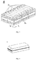
- Fig. 4 is a schematic diagram showing an example of the battery pack 1 of the present application.
- Fig. 5 is an exploded view showing an example of the battery pack 1 of the present application shown in Fig. 4 .
- the battery pack 1 may include a battery box and a plurality of battery modules 4 disposed in the battery box.
- the battery box includes an upper box body 2 and a lower box body 3.
- the upper box body 2 is used to cover the lower box body 3 and form a closed space for receiving the battery modules 4.
- the plurality of battery modules 4 may be arranged in the battery box in any manner.
- the electric apparatus of the present application includes at least one of the battery module or battery pack of the present application, and the battery module or battery pack may be used as a power source of the electric apparatus, and may also be used as an energy storage unit of the electric apparatus.
- the electric apparatus includes, but is not limited to, a mobile digital apparatus (e.g., a mobile phone, a notebook computer, etc.), an electric vehicle (e.g., a pure electric vehicle, a hybrid electric vehicle, a plug-in hybrid electric vehicle, an electric bicycle, an electric scooter, an electric golf vehicle, an electric truck, etc.), an electric train, a ship, a satellite, an energy storage system, etc.
- Fig. 6 is a schematic diagram showing an example of the electric apparatus using the battery module of the present application as a power source.
- the electric apparatus is a pure electric vehicle, a hybrid electric vehicle, or a plug-in hybrid electric vehicle.
- battery packs or battery modules may be used.
- the present application provides a method for manufacturing a battery module, including the following steps:
- the present application proposes a device for manufacturing a battery module, including:
- the battery module manufactured by the manufacturing method and manufacturing device of the present application can significantly improve the control accuracy of the BMS, effectively prevent the overcharging phenomenon of the battery cells inside the hybrid series battery module, and greatly improve the safety of the battery module.
- a positive electrode active material, a conductive carbon Super P, and a binder polyvinylidene fluoride (PVDF), at a weight ratio of 95:3:2, are mixed in an appropriate amount of N-methylpyrrolidone (NMP) solvent under fully stirring, to form a uniform and stable slurry with a viscosity of 15000 mPa•s, and the slurry produces no gelling, stratification or sedimentation and other phenomena within 38 hours of standing.
- NMP N-methylpyrrolidone
- the positive electrode material slurry is uniformly coated on a positive electrode current collector Al foil, after drying, the electrode plate is cold-pressed to a designed compaction and is slit for later use, to obtain a positive electrode plate.
- lithium hexafluorophosphate is uniformly dissolved in the mixed solvent for later use (the lithium hexafluorophosphate has a concentration of 1.1 M/L) to obtain an electrolyte solution.
- Negative electrode active materials such as graphite, conductive carbon, a binder polystyrene-butadiene copolymer (SBR), a thickener sodium carboxymethylcellulose (CMC), at a weight ratio of 95:2:2:1, are mixed in an appropriate amount of water solvent under fully stirring, to form a uniform and stable negative electrode slurry; the slurry is evenly coated on a negative electrode current collector Cu foil, after drying, the electrode plate is cold-pressed to a designed compactness and is slit for later use.
- SBR binder polystyrene-butadiene copolymer
- CMC thickener sodium carboxymethylcellulose
- PP is used as a separator.
- the above-mentioned positive electrode plate, separator and negative electrode plate are wound together by using the conventional battery cell manufacturing process to form a bare battery cell, then the bare battery cell is placed in a battery shell, the above-mentioned electrolyte is injected, then the procedures of forming and sealing are carried out, and a rechargeable power battery cell is obtained.
- the first type of battery cells and 10 the second type of battery cells are taken, and the first type of battery cells and the second type of battery cells are arranged at intervals and electrically connected in series.
- a method for testing an OCV change curve of a battery cell in a range from 0% to 100% SOC includes the following steps:
- the nominal current can be freely selected according to the capacity of the battery module. For example, when the capacity of the battery module is 50 Ah, the nominal current may be 50 A. For another example, when the capacity of the battery module is 100 Ah, the nominal current may be 100 A.
- the charge termination voltage and the discharge termination voltage can be determined by referring to the provisions in the technical specification of the product or the GBT certification documents for battery cells/battery modules.
- the discharge battery balance rate of the battery cell the discharge capacity of the negative electrode plate per unit area/ the charge capacity of the positive electrode plate per unit area.
- the discharge capacity of the positive electrode plate or the negative electrode plate can be tested by the following steps:
- CapO initial capacity
- Steps 1) to 4) are a charge and discharge cycle of the battery module. Steps 1) to 4) as above are repeated for 1500 times, the discharge capacity measured at the 1500th time is denoted as Capn, and the capacity retention rate at the 1500th time is: Capn/Cap0 ⁇ 100%.
- C represents a rated capacity of the battery cell
- the charge/discharge current is a rate multiplied by the rated capacity of the battery cell
- the rated capacity is subject to the capacity of the battery cell identified in the GBT certification document of the battery cell, or the battery module of the battery cell, or the battery pack of the battery cell.
- the battery module is charged at a constant current rate of 1 C to an upper limit cut-off voltage (the upper limit cut-off voltage of the battery module can be formulated with reference to the specification of the battery module), then charged at the constant upper limit cut-off voltage to the current of 0.05 C, and stood for 30 minute. Then the battery module is fixed and placed on an overcharge safety test device, and the ambient temperature is controlled at 25 ⁇ 2°C. After standing for 5 min, the battery module at state of being fully charged is overcharged at the rate of 1 C, and the real-time voltage and temperature changes of each battery cell are recorded until the charging stops. 6 battery modules are tested in each example and comparative example, the first type of battery cell in the battery module is disassembled to observe lithium deposition on the surface of the negative electrode plate, and the number of lithium deposition cells is recorded.
- the positive electrode active material was LiFePO 4
- the discharge battery balance rate CB1 was 1.04
- the change rate ⁇ OCV/ ⁇ SOC in the OCV relative to SOC of the first type of battery cells was 0.07 when the SOC was in the range from 30% to 80%, and was 0.28 when the SOC was in the range from 90% to 98%.
- LFP LiFePO 4
- NCM LiNi 0.55 Co 0.12 Mn 0.33 O 2
- the battery module also included 10 first type of battery cells and 10 second type of battery cells, wherein the discharge battery balance rates CB1 of the first type of battery cells and that of the second type of battery cells CB2 were the same with those in Example 1, except for the differences shown in Table 1.
- the probability of lithium deposition due to overcharge of the first type of battery cells in Example 1 was 2/10
- the probability of lithium deposition due to overcharge of the first type of battery cells in Example 2 was 1/10
- the probability of lithium deposition due to overcharge of the first type of battery cells in Examples 3-7 was 0/10.
- both the first type of battery cells and the second type of battery cells were LFP, and the change rate ⁇ OCV/ ⁇ SOC in the OCV relative to the SOC was 0.71 when the SOC of the battery module was in the range from 90% to 98% during charging.
- the change rates ⁇ OCV/ ⁇ SOC of the first and second types of battery cells in the battery module changed slowly, the probability of lithium evolution due to overcharge of the first type of battery cells in the battery module of Comparative Example 1 was very high (8/10).
- Comparative Example 2 Although the change rate ⁇ OCV/ ⁇ SOC in the OCV relative to the SOC was 1.53 when the SOC of the second type of battery cells was in the range from 90% to 98% during charging, the probability of lithium deposition due to overcharge of the first type of battery cells in the battery module of Comparative Example 2 was still high (5/10), because the positive electrode active material for the first type of battery cells was LFP, and the positive electrode active material for the second type of battery cells was NCM, without any optimized design for the doping of the positive electrode active material of the first type of battery cells or the second type of battery cells.
- the first type of battery cells and the second type of battery cells of different chemical systems were connected in series, and the change rate ⁇ OCV/ ⁇ SOC in the OCV relative to the SOC, when the second type of battery cells was nearly fully charged, was adjusted to the range of 3 - 9 mV/%SOC, through this optimized design, the probability of lithium deposition due to overcharge of the first type of battery cells in the battery modules of Examples 1-7 was greatly reduced compared with the battery modules that were not subjected to optimization design in Comparative Examples 1 and 2. As a result, the safety of the battery module was significantly improved.
- the battery cells were prepared by the method similar to the preparation of battery cells in Examples 1-7 above.
- the first type of battery cells in Examples 8-12 were the same as those in Example 3, except for the difference in the specific parameters of the second type of battery cells in Examples 8-12.
- Table 2 First type of battery cells Second type of battery cells Positive electrode active material and mass ratio Second type of battery cells Discharge cell balance rate CB2 ⁇ OCV/ ⁇ SOC of second type of battery cells (30%-80% SOC) ⁇ OCV/ ⁇ SOC of second type of battery cells (90%98% SOC) ⁇ OCV/ ⁇ SOC ratio Q of first and second types of battery cells Number of lithium-deposition cells of first type when the battery module is overcharged Capacity retention rate of battery module at 1500th cycle
- Active material LiFe 0.98 Ti 0.02 PO 4 CB1 1.04, ⁇ OCV/ ⁇ SOC at 30%-80% SOC: 0.15 mV/%SOC, ⁇ OCV/ ⁇ SOC at 90%-98%SOC: 0.42 mV/%SOC L
- Example 11 wherein CB2 of the second type of battery cells did not satisfy 1.00 ⁇ CB2 ⁇ 1.16, the probability of lithium deposition due to overcharge of the first type of battery cells in the battery module was not zero.
- Example 12 wherein CB2 of the second type of battery cells did not satisfy 1.00 ⁇ CB2 ⁇ 1.16, although the probability of lithium deposition due to overcharge of the first type of battery cells in the battery module was also low, the capacity retention rate of the battery module at the 1500th cycle was relatively low.
- the battery cells were prepared by the method similar to the preparation of battery cells in Examples 1-7 as above.
- the second battery cells in Examples 13-21 were the same as those in Example 3, except that the specific parameters of the first battery cells in Examples 13-21, see Table 3 for details.
- Table 3 First type of battery cells Positive electrode active material
- First type of battery cells Discharge battery balance rate CB1 ⁇ OCV/ ⁇ SO C of first type of battery cells (30%-80% SOC) ⁇ OCV/ ⁇ SO C of first type of battery cells (90%-98% SOC) ⁇ OCV/ ⁇ SOC ratio of first and second types of battery cells
- Second type of battery cells Numbers of lithium-depositing cells of first type when the battery module is overcharged Capacity retention rate of battery module at 1500th cycle
- Example 3 LiFe 0.98 Ti 0.02 PO 4 1.04 0.15 0.42 10.74
- the curvature characteristics of the second type of battery cells range were set in the high SOC, and the discharge battery balance rate of the first type of battery cells was further optimized.
- the overcharge of the battery cells inside the hybrid series battery module was effectively prevented, the safety of the battery module was greatly improve, and the service life of the battery module was further prolonged.
Landscapes
- Chemical & Material Sciences (AREA)
- Chemical Kinetics & Catalysis (AREA)
- Electrochemistry (AREA)
- General Chemical & Material Sciences (AREA)
- Inorganic Chemistry (AREA)
- Composite Materials (AREA)
- Engineering & Computer Science (AREA)
- Materials Engineering (AREA)
- Manufacturing & Machinery (AREA)
- Crystallography & Structural Chemistry (AREA)
- Secondary Cells (AREA)
- Battery Electrode And Active Subsutance (AREA)
Applications Claiming Priority (1)
| Application Number | Priority Date | Filing Date | Title |
|---|---|---|---|
| PCT/CN2021/084743 WO2022205221A1 (fr) | 2021-03-31 | 2021-03-31 | Module de batterie, bloc-batterie, appareil électrique et procédé de fabrication et dispositif de fabrication pour module de batterie |
Publications (2)
| Publication Number | Publication Date |
|---|---|
| EP4092804A1 true EP4092804A1 (fr) | 2022-11-23 |
| EP4092804A4 EP4092804A4 (fr) | 2023-05-17 |
Family
ID=83457695
Family Applications (1)
| Application Number | Title | Priority Date | Filing Date |
|---|---|---|---|
| EP21878762.0A Pending EP4092804A4 (fr) | 2021-03-31 | 2021-03-31 | Module de batterie, bloc-batterie, appareil électrique et procédé de fabrication et dispositif de fabrication pour module de batterie |
Country Status (4)
| Country | Link |
|---|---|
| US (1) | US11764436B2 (fr) |
| EP (1) | EP4092804A4 (fr) |
| CN (1) | CN115485907A (fr) |
| WO (1) | WO2022205221A1 (fr) |
Family Cites Families (10)
| Publication number | Priority date | Publication date | Assignee | Title |
|---|---|---|---|---|
| JP5100143B2 (ja) | 2007-02-05 | 2012-12-19 | 三洋電機株式会社 | 電池ユニット |
| US20120231341A1 (en) * | 2011-03-09 | 2012-09-13 | Jun-Sik Kim | Positive active material, and electrode and lithium battery containing the positive active material |
| CN103311562B (zh) * | 2012-03-12 | 2015-06-03 | 联想(北京)有限公司 | 一种充电电池及其充电控制方法和放电控制方法 |
| CN105811028A (zh) * | 2016-03-23 | 2016-07-27 | 合肥国轩高科动力能源有限公司 | 一种锂离子电池系统的soc状态估计方法 |
| CN110061531B (zh) * | 2018-01-19 | 2023-03-14 | 丰郅(上海)新能源科技有限公司 | 储能电池的均衡方法 |
| CN208674305U (zh) | 2018-09-04 | 2019-03-29 | 东莞塔菲尔新能源科技有限公司 | 一种电池模组 |
| CN111781504B (zh) * | 2020-08-03 | 2023-09-01 | 北京理工大学 | 一种锂离子动力电池老化状态识别与开路电压重构方法 |
| CN111916844B (zh) * | 2020-08-13 | 2022-04-15 | 东莞新能安科技有限公司 | 电化学装置及电子装置 |
| EP4047712A4 (fr) * | 2020-12-24 | 2023-05-03 | Contemporary Amperex Technology Co., Limited | Ensemble batterie, bloc-batterie, appareil électrique, et procédé de fabrication et dispositif de fabrication pour ensemble batterie |
| EP4047711A4 (fr) * | 2020-12-24 | 2022-11-30 | Contemporary Amperex Technology Co., Limited | Module de batterie, bloc-batterie, appareil électronique, et procédé de fabrication de module de batterie et dispositif de fabrication |
-
2021
- 2021-03-31 EP EP21878762.0A patent/EP4092804A4/fr active Pending
- 2021-03-31 CN CN202180004802.8A patent/CN115485907A/zh active Pending
- 2021-03-31 WO PCT/CN2021/084743 patent/WO2022205221A1/fr unknown
-
2022
- 2022-08-17 US US17/889,422 patent/US11764436B2/en active Active
Also Published As
| Publication number | Publication date |
|---|---|
| CN115485907A (zh) | 2022-12-16 |
| US20220393292A1 (en) | 2022-12-08 |
| US11764436B2 (en) | 2023-09-19 |
| WO2022205221A1 (fr) | 2022-10-06 |
| EP4092804A4 (fr) | 2023-05-17 |
Similar Documents
| Publication | Publication Date | Title |
|---|---|---|
| WO2022133963A1 (fr) | Module de batterie, bloc-batterie, appareil électronique, et procédé de fabrication de module de batterie et dispositif de fabrication | |
| EP4047701A1 (fr) | Bloc-batterie, boîtier de batterie, appareil électrique, et procédé et dispositif de fabrication de bloc-batterie | |
| EP4362156A1 (fr) | Batterie au lithium-ion, module de batterie, bloc-batterie et appareil électrique | |
| CN116682936B (zh) | 电池及其制备方法、用电装置 | |
| US20230378546A1 (en) | Secondary battery, battery module, battery pack, and electrical device | |
| US11749999B2 (en) | Battery unit, battery pack, electrical device, method and apparatus for manufacturing battery unit, and method for controlling battery unit | |
| EP4280297A1 (fr) | Plaque anodique d'une batterie lithium-ion et application associée | |
| EP4235902A1 (fr) | Feuille d'électrode négative et procédé de préparation associé, batterie secondaire, module de batterie, bloc-batterie et appareil consommateur de puissance | |
| EP4092804A1 (fr) | Module de batterie, bloc-batterie, appareil électrique et procédé de fabrication et dispositif de fabrication pour module de batterie | |
| EP4106097A1 (fr) | Module de batterie, bloc-batterie, appareil électrique et procédé et dispositif de fabrication pour module de batterie | |
| EP4213264A1 (fr) | Électrolyte, batterie secondaire, module de batterie, bloc-batterie et dispositif électrique | |
| WO2024026654A1 (fr) | Feuille d'électrode négative, batterie secondaire et dispositif électrique | |
| WO2024040472A1 (fr) | Batterie secondaire, module de batterie, bloc-batterie et appareil électrique | |
| EP4376182A1 (fr) | Bloc-batterie et dispositif électrique | |
| US20230344011A1 (en) | Electrode assembly, secondary battery, battery module, battery pack and electrical device | |
| EP4325616A1 (fr) | Batterie secondaire, module de batterie, bloc-batterie et dispositif électrique | |
| EP4293807A1 (fr) | Bloc-batterie et dispositif électrique | |
| WO2023082866A1 (fr) | Batterie secondaire, procédé de préparation de batterie secondaire, module de batterie, bloc-batterie et appareil électrique | |
| US20230112421A1 (en) | Electrode assembly, secondary battery, battery module, battery pack and electrical device | |
| US20230216028A1 (en) | Negative electrode plate, secondary battery, battery module, battery pack, and electrical device | |
| EP4113685A1 (fr) | Groupe de batteries, bloc-batterie, appareil électrique, et procédé de fabrication et dispositif de fabrication pour groupe de batteries | |
| CN117996215A (zh) | 电池及其制备方法、用电装置 | |
| KR20240001313A (ko) | 양극 활물질, 이차 전지, 전지 모듈, 전지 팩 및 전기 장치 | |
| KR20240021293A (ko) | 전해액, 이차전지, 배터리모듈, 배터리팩 및 전기기기 | |
| KR20230054608A (ko) | 음극 극판, 이차 전지, 전지 모듈, 전지 팩 및 전기 장치 |
Legal Events
| Date | Code | Title | Description |
|---|---|---|---|
| STAA | Information on the status of an ep patent application or granted ep patent |
Free format text: STATUS: UNKNOWN |
|
| STAA | Information on the status of an ep patent application or granted ep patent |
Free format text: STATUS: THE INTERNATIONAL PUBLICATION HAS BEEN MADE |
|
| PUAI | Public reference made under article 153(3) epc to a published international application that has entered the european phase |
Free format text: ORIGINAL CODE: 0009012 |
|
| STAA | Information on the status of an ep patent application or granted ep patent |
Free format text: STATUS: REQUEST FOR EXAMINATION WAS MADE |
|
| 17P | Request for examination filed |
Effective date: 20220422 |
|
| AK | Designated contracting states |
Kind code of ref document: A1 Designated state(s): AL AT BE BG CH CY CZ DE DK EE ES FI FR GB GR HR HU IE IS IT LI LT LU LV MC MK MT NL NO PL PT RO RS SE SI SK SM TR |
|
| REG | Reference to a national code |
Ref country code: DE Ref legal event code: R079 Free format text: PREVIOUS MAIN CLASS: H01M0010420000 Ipc: H01M0050267000 |
|
| A4 | Supplementary search report drawn up and despatched |
Effective date: 20230419 |
|
| RIC1 | Information provided on ipc code assigned before grant |
Ipc: H01M 4/58 20100101ALI20230413BHEP Ipc: H01M 50/51 20210101ALI20230413BHEP Ipc: H01M 50/204 20210101ALI20230413BHEP Ipc: H01M 10/0525 20100101ALI20230413BHEP Ipc: H01M 4/525 20100101ALI20230413BHEP Ipc: H01M 4/505 20100101ALI20230413BHEP Ipc: H01M 50/267 20210101AFI20230413BHEP |