EP4092633A1 - Method and device for lane-changing prediction of target vehicle - Google Patents
Method and device for lane-changing prediction of target vehicle Download PDFInfo
- Publication number
- EP4092633A1 EP4092633A1 EP22165556.6A EP22165556A EP4092633A1 EP 4092633 A1 EP4092633 A1 EP 4092633A1 EP 22165556 A EP22165556 A EP 22165556A EP 4092633 A1 EP4092633 A1 EP 4092633A1
- Authority
- EP
- European Patent Office
- Prior art keywords
- lane
- target vehicle
- ccs
- machine learning
- learning model
- Prior art date
- Legal status (The legal status is an assumption and is not a legal conclusion. Google has not performed a legal analysis and makes no representation as to the accuracy of the status listed.)
- Pending
Links
Images
Classifications
-
- B—PERFORMING OPERATIONS; TRANSPORTING
- B60—VEHICLES IN GENERAL
- B60W—CONJOINT CONTROL OF VEHICLE SUB-UNITS OF DIFFERENT TYPE OR DIFFERENT FUNCTION; CONTROL SYSTEMS SPECIALLY ADAPTED FOR HYBRID VEHICLES; ROAD VEHICLE DRIVE CONTROL SYSTEMS FOR PURPOSES NOT RELATED TO THE CONTROL OF A PARTICULAR SUB-UNIT
- B60W30/00—Purposes of road vehicle drive control systems not related to the control of a particular sub-unit, e.g. of systems using conjoint control of vehicle sub-units, or advanced driver assistance systems for ensuring comfort, stability and safety or drive control systems for propelling or retarding the vehicle
- B60W30/18—Propelling the vehicle
- B60W30/18009—Propelling the vehicle related to particular drive situations
- B60W30/18163—Lane change; Overtaking manoeuvres
-
- G—PHYSICS
- G06—COMPUTING; CALCULATING OR COUNTING
- G06V—IMAGE OR VIDEO RECOGNITION OR UNDERSTANDING
- G06V20/00—Scenes; Scene-specific elements
- G06V20/50—Context or environment of the image
- G06V20/56—Context or environment of the image exterior to a vehicle by using sensors mounted on the vehicle
- G06V20/58—Recognition of moving objects or obstacles, e.g. vehicles or pedestrians; Recognition of traffic objects, e.g. traffic signs, traffic lights or roads
-
- G—PHYSICS
- G08—SIGNALLING
- G08G—TRAFFIC CONTROL SYSTEMS
- G08G1/00—Traffic control systems for road vehicles
- G08G1/16—Anti-collision systems
- G08G1/167—Driving aids for lane monitoring, lane changing, e.g. blind spot detection
-
- B—PERFORMING OPERATIONS; TRANSPORTING
- B60—VEHICLES IN GENERAL
- B60W—CONJOINT CONTROL OF VEHICLE SUB-UNITS OF DIFFERENT TYPE OR DIFFERENT FUNCTION; CONTROL SYSTEMS SPECIALLY ADAPTED FOR HYBRID VEHICLES; ROAD VEHICLE DRIVE CONTROL SYSTEMS FOR PURPOSES NOT RELATED TO THE CONTROL OF A PARTICULAR SUB-UNIT
- B60W40/00—Estimation or calculation of non-directly measurable driving parameters for road vehicle drive control systems not related to the control of a particular sub unit, e.g. by using mathematical models
- B60W40/10—Estimation or calculation of non-directly measurable driving parameters for road vehicle drive control systems not related to the control of a particular sub unit, e.g. by using mathematical models related to vehicle motion
- B60W40/105—Speed
-
- B—PERFORMING OPERATIONS; TRANSPORTING
- B60—VEHICLES IN GENERAL
- B60W—CONJOINT CONTROL OF VEHICLE SUB-UNITS OF DIFFERENT TYPE OR DIFFERENT FUNCTION; CONTROL SYSTEMS SPECIALLY ADAPTED FOR HYBRID VEHICLES; ROAD VEHICLE DRIVE CONTROL SYSTEMS FOR PURPOSES NOT RELATED TO THE CONTROL OF A PARTICULAR SUB-UNIT
- B60W50/00—Details of control systems for road vehicle drive control not related to the control of a particular sub-unit, e.g. process diagnostic or vehicle driver interfaces
-
- G—PHYSICS
- G06—COMPUTING; CALCULATING OR COUNTING
- G06F—ELECTRIC DIGITAL DATA PROCESSING
- G06F18/00—Pattern recognition
- G06F18/20—Analysing
- G06F18/24—Classification techniques
- G06F18/241—Classification techniques relating to the classification model, e.g. parametric or non-parametric approaches
- G06F18/2411—Classification techniques relating to the classification model, e.g. parametric or non-parametric approaches based on the proximity to a decision surface, e.g. support vector machines
-
- G—PHYSICS
- G06—COMPUTING; CALCULATING OR COUNTING
- G06F—ELECTRIC DIGITAL DATA PROCESSING
- G06F18/00—Pattern recognition
- G06F18/20—Analysing
- G06F18/24—Classification techniques
- G06F18/241—Classification techniques relating to the classification model, e.g. parametric or non-parametric approaches
- G06F18/2415—Classification techniques relating to the classification model, e.g. parametric or non-parametric approaches based on parametric or probabilistic models, e.g. based on likelihood ratio or false acceptance rate versus a false rejection rate
-
- G—PHYSICS
- G06—COMPUTING; CALCULATING OR COUNTING
- G06F—ELECTRIC DIGITAL DATA PROCESSING
- G06F18/00—Pattern recognition
- G06F18/20—Analysing
- G06F18/25—Fusion techniques
- G06F18/254—Fusion techniques of classification results, e.g. of results related to same input data
-
- G—PHYSICS
- G06—COMPUTING; CALCULATING OR COUNTING
- G06V—IMAGE OR VIDEO RECOGNITION OR UNDERSTANDING
- G06V20/00—Scenes; Scene-specific elements
- G06V20/50—Context or environment of the image
- G06V20/56—Context or environment of the image exterior to a vehicle by using sensors mounted on the vehicle
- G06V20/588—Recognition of the road, e.g. of lane markings; Recognition of the vehicle driving pattern in relation to the road
-
- B—PERFORMING OPERATIONS; TRANSPORTING
- B60—VEHICLES IN GENERAL
- B60W—CONJOINT CONTROL OF VEHICLE SUB-UNITS OF DIFFERENT TYPE OR DIFFERENT FUNCTION; CONTROL SYSTEMS SPECIALLY ADAPTED FOR HYBRID VEHICLES; ROAD VEHICLE DRIVE CONTROL SYSTEMS FOR PURPOSES NOT RELATED TO THE CONTROL OF A PARTICULAR SUB-UNIT
- B60W50/00—Details of control systems for road vehicle drive control not related to the control of a particular sub-unit, e.g. process diagnostic or vehicle driver interfaces
- B60W2050/0001—Details of the control system
- B60W2050/0019—Control system elements or transfer functions
-
- B—PERFORMING OPERATIONS; TRANSPORTING
- B60—VEHICLES IN GENERAL
- B60W—CONJOINT CONTROL OF VEHICLE SUB-UNITS OF DIFFERENT TYPE OR DIFFERENT FUNCTION; CONTROL SYSTEMS SPECIALLY ADAPTED FOR HYBRID VEHICLES; ROAD VEHICLE DRIVE CONTROL SYSTEMS FOR PURPOSES NOT RELATED TO THE CONTROL OF A PARTICULAR SUB-UNIT
- B60W2520/00—Input parameters relating to overall vehicle dynamics
- B60W2520/10—Longitudinal speed
-
- B—PERFORMING OPERATIONS; TRANSPORTING
- B60—VEHICLES IN GENERAL
- B60W—CONJOINT CONTROL OF VEHICLE SUB-UNITS OF DIFFERENT TYPE OR DIFFERENT FUNCTION; CONTROL SYSTEMS SPECIALLY ADAPTED FOR HYBRID VEHICLES; ROAD VEHICLE DRIVE CONTROL SYSTEMS FOR PURPOSES NOT RELATED TO THE CONTROL OF A PARTICULAR SUB-UNIT
- B60W2520/00—Input parameters relating to overall vehicle dynamics
- B60W2520/12—Lateral speed
-
- B—PERFORMING OPERATIONS; TRANSPORTING
- B60—VEHICLES IN GENERAL
- B60W—CONJOINT CONTROL OF VEHICLE SUB-UNITS OF DIFFERENT TYPE OR DIFFERENT FUNCTION; CONTROL SYSTEMS SPECIALLY ADAPTED FOR HYBRID VEHICLES; ROAD VEHICLE DRIVE CONTROL SYSTEMS FOR PURPOSES NOT RELATED TO THE CONTROL OF A PARTICULAR SUB-UNIT
- B60W2552/00—Input parameters relating to infrastructure
- B60W2552/53—Road markings, e.g. lane marker or crosswalk
-
- B—PERFORMING OPERATIONS; TRANSPORTING
- B60—VEHICLES IN GENERAL
- B60W—CONJOINT CONTROL OF VEHICLE SUB-UNITS OF DIFFERENT TYPE OR DIFFERENT FUNCTION; CONTROL SYSTEMS SPECIALLY ADAPTED FOR HYBRID VEHICLES; ROAD VEHICLE DRIVE CONTROL SYSTEMS FOR PURPOSES NOT RELATED TO THE CONTROL OF A PARTICULAR SUB-UNIT
- B60W2554/00—Input parameters relating to objects
- B60W2554/40—Dynamic objects, e.g. animals, windblown objects
- B60W2554/404—Characteristics
- B60W2554/4045—Intention, e.g. lane change or imminent movement
-
- B—PERFORMING OPERATIONS; TRANSPORTING
- B60—VEHICLES IN GENERAL
- B60W—CONJOINT CONTROL OF VEHICLE SUB-UNITS OF DIFFERENT TYPE OR DIFFERENT FUNCTION; CONTROL SYSTEMS SPECIALLY ADAPTED FOR HYBRID VEHICLES; ROAD VEHICLE DRIVE CONTROL SYSTEMS FOR PURPOSES NOT RELATED TO THE CONTROL OF A PARTICULAR SUB-UNIT
- B60W2554/00—Input parameters relating to objects
- B60W2554/80—Spatial relation or speed relative to objects
- B60W2554/801—Lateral distance
-
- B—PERFORMING OPERATIONS; TRANSPORTING
- B60—VEHICLES IN GENERAL
- B60W—CONJOINT CONTROL OF VEHICLE SUB-UNITS OF DIFFERENT TYPE OR DIFFERENT FUNCTION; CONTROL SYSTEMS SPECIALLY ADAPTED FOR HYBRID VEHICLES; ROAD VEHICLE DRIVE CONTROL SYSTEMS FOR PURPOSES NOT RELATED TO THE CONTROL OF A PARTICULAR SUB-UNIT
- B60W2554/00—Input parameters relating to objects
- B60W2554/80—Spatial relation or speed relative to objects
- B60W2554/802—Longitudinal distance
Definitions
- the invention relates to the field of lane-changing prediction of a target vehicle, and in particular, to a method and device for lane-changing prediction of a target vehicle, a computer storage medium, and a vehicle.
- Dynamic movement of other moving vehicles on a road has critical influences on road traffic safety.
- the selection of a driving strategy for intelligent connected vehicles needs to take into consideration motion behaviors of other vehicles, mainly including lane changing and lane keeping of the other vehicles, where the lane changing of the vehicles poses a significant threat to road traffic safety. Therefore, the prediction of a lane-changing intention of vehicles on two sides of a present vehicle on a road can effectively prevent traffic incidents from happening and improve the driving safety.
- a method for lane-changing prediction of a target vehicle including: receiving a velocity and a position of the target vehicle; respectively obtaining, based on the velocity and the position of the target vehicle, a first lane-changing probability and a second lane-changing probability of the target vehicle by using a first machine learning model and
- a second machine learning model determining a possibility of lane changing of the target vehicle based on the first lane-changing probability and the second lane-changing probability, the first machine learning model and the second machine learning model being pre-trained and being different from each other.
- the velocity and the position of the target vehicle include: a longitudinal distance d x of the target vehicle in a vehicle coordinate system of a present vehicle; a lateral distance d y_ccs of the target vehicle in a lane line coordinate system; and a lateral velocity v y_ccs and a longitudinal velocity v x_ccs of the target vehicle in the lane line coordinate system.
- the first machine learning model is trained by using at least the lateral distance d y_ccs of the target vehicle in the lane line coordinate system and the lateral velocity v y_ccs of the target vehicle in the lane line coordinate system as feature parameters.
- the second machine learning model is trained by using at least the longitudinal distance d x of the target vehicle in the vehicle coordinate system of the present vehicle, the lateral distance d y_ccs of the target vehicle in the lane line coordinate system, and the lateral velocity v y_ccs and the longitudinal velocity v x_ccs of the target vehicle in the lane line coordinate system as feature parameters.
- the determining a possibility of lane changing of the target vehicle based on the first lane-changing probability and the second lane-changing probability includes: when both the first lane-changing probability and the second lane-changing probability satisfy a threshold condition, considering lane-changing prediction of the target vehicle successful and outputting a lane-changing probability P of the target vehicle.
- a device for lane-changing prediction of a target vehicle including: a receiving apparatus configured to receive a velocity and a position of the target vehicle; a calculation apparatus configured to respectively obtain, based on the velocity and the position of the target vehicle, a first lane-changing probability and a second lane-changing probability of the target vehicle by using a first machine learning model and a second machine learning model; and a determination apparatus configured to determine a possibility of lane changing of the target vehicle based on the first lane-changing probability and the second lane-changing probability, the first machine learning model and the second machine learning model being pre-trained and being different from each other.
- the velocity and the position of the target vehicle include: a longitudinal distance d x of the target vehicle in a vehicle coordinate system of a present vehicle; a lateral distance d y_ccs of the target vehicle in a lane line coordinate system; and a lateral velocity v y_ccs and a longitudinal velocity v _ccs of the target vehicle in the lane line coordinate system.
- the above device further includes: a first training apparatus configured to train the first machine learning model, wherein at least the lateral distance d y_ccs of the target vehicle in the lane line coordinate system and the lateral velocity v y_ccs of the target vehicle in the lane line coordinate system are used as feature parameters for the first machine learning model.
- the above device further includes: a second training apparatus configured to train the second machine learning model, wherein at least the longitudinal distance d x of the target vehicle in the vehicle coordinate system of the present vehicle, the lateral distance d y_ccs of the target vehicle in the lane line coordinate system, and the lateral velocity v y_ccs and the longitudinal velocity v x_ccs of the target vehicle in the lane line coordinate system are used as feature parameters for the second machine learning model.
- the determination apparatus is configured to: when both the first lane-changing probability and the second lane-changing probability satisfy a threshold condition, output a lane-changing probability P of the target vehicle.
- a computer storage medium including instructions, where when the instructions are run, the method as described above is performed.
- a vehicle including the device as described above.
- two different models namely, the first machine learning model and the second machine learning model
- the first machine learning model and the second machine learning model are combined to provide a comprehensive determination of a lane-changing intention of the target vehicle, such that the accuracy and stability of a prediction system is ensured, thereby improving the driving safety.
- control logic of the invention may be included on a computer-readable medium as executable program instructions, which are implemented by a processor or the like.
- the computer-readable medium include, but are not limited to, a ROM, a RAM, an optical disc, a magnetic tape, a floppy disk, a flash drive, a smart card, and an optical data storage apparatus.
- a computer-readable recording medium may also be distributed in a computer system connected to a network, so that the computer-readable medium is stored and implemented in a distributed manner, for example, through a vehicle telematics service or a controller area network (CAN).
- CAN controller area network
- vehicle or other similar terms used herein includes general motor vehicles, such as passenger vehicles (including sport utility vehicles, buses, trucks, etc.), various commercial vehicles, etc., and includes hybrid vehicles, electric vehicles, etc.
- a hybrid vehicle is a vehicle with two or more power sources, such as a vehicle powered by a gasoline engine and an electric motor.
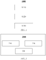
- FIG. 1 is a schematic flowchart of a method 1000 for lane-changing prediction of a target vehicle according to an embodiment of the invention. As shown in FIG. 1 , the method 1000 for lane-changing prediction of a target vehicle includes the following steps:
- target vehicle is another vehicle other than a present vehicle.
- the target vehicle to be subjected to lane-changing prediction is on the front left or front right of the present vehicle.
- Machine learning refers to a process of using some algorithms to guide a computer to obtain a proper model based on known data and then using the model to make a determination on a new situation. Therefore, in the context of the invention, the "first machine learning model” and the “second machine learning model” are different models obtained by a computer under the guidance of different algorithms, and the models may be used to determine (or predict) a lane-changing probability of the target vehicle.
- the use of a single model for lane-changing prediction of the target vehicle may produce a large determination error.
- the present vehicle may erroneously brake because of the target vehicle, and when severe, traffic accidents, such as rear-end collision, may be caused.
- the use of the two models, namely, the first machine learning model and the second machine learning model, for lane-changing prediction of the target vehicle improves the accuracy of the lane-changing prediction of the target vehicle.
- the velocity and the position of the target vehicle include: a longitudinal distance d x of the target vehicle in a vehicle coordinate system of a present vehicle; a lateral distance d y_ccs of the target vehicle in a lane line coordinate system; and a lateral velocity v y_ccs and a longitudinal velocity v x_ccs of the target vehicle in the lane line coordinate system.
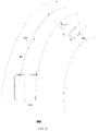
- FIG. 3 is a schematic diagram of a scenario 3000 of predicting a lane-changing probability of a target vehicle based on a motion status of the target vehicle.
- a present vehicle is denoted by a reference numeral 310
- the target vehicle is denoted by a reference numeral 320.
- a center of a front bumper of the vehicle is, for example, used as an origin, which is denoted by a point O in FIG. 3 .
- a lane line coordinate system may be a Frenet coordinate system, in which a lane centerline is used as a reference line, and variables s and d are used to describe positions of the vehicle on a road.
- the s coordinates represent a distance along the road (also referred to as a longitudinal displacement or a longitudinal distance), and the d coordinates represent a position relative to the left or right of the road (also referred to as a lateral displacement or a lateral distance).
- a projection point of the vehicle 320 on the reference line (namely, a lane centerline 330) is C, and therefore, a distance between the point C and a lateral position B of the target vehicle 320 in the vehicle coordinate system is the lateral distance d y_ccs of the target vehicle in the lane line coordinate system.
- the first machine learning model is trained by using at least the lateral distance d y_ccs of the target vehicle in the lane line coordinate system and the lateral velocity v y_ccs of the target vehicle in the lane line coordinate system as feature parameters.
- c 1 to c 5 are coefficients obtained after training of the first machine learning model.
- the model parameters c 1 to c 5 are obtained after training, by using a big data learning method, based on the velocity and the position of the target vehicle. Then, the velocity and the position of the target vehicle can be input to obtain a probability value of lane changing of the target vehicle.
- the second machine learning model is trained by using at least the longitudinal distance d x of the target vehicle in the vehicle coordinate system of the present vehicle, the lateral distance d y_ccs of the target vehicle in the lane line coordinate system, and the lateral velocity v y_ccs and the longitudinal velocity v x_ccs of the target vehicle in the lane line coordinate system as feature parameters.
- step S130 includes: when both the first lane-changing probability and the second lane-changing probability satisfy a threshold condition, considering lane-changing prediction of the target vehicle successful and outputting a lane-changing probability P of the target vehicle.
- a final lane-changing probability P w1 ⁇ P1 + w2 ⁇ P2, where w1 and w2 are weights and may be adjusted as needed.
- the method for lane-changing prediction of a target vehicle provided in the one or more embodiments of the invention can be implemented by using a computer program.
- a computer storage medium for example, a USB flash drive
- the method for lane-changing prediction of a target vehicle according to one or more embodiments of the invention can be performed by executing the computer program.
- FIG. 2 is a schematic structural diagram of a device 2000 for lane-changing prediction of a target vehicle according to an embodiment of the invention.
- the device 2000 for lane-changing prediction of a target vehicle includes: a receiving apparatus 210, a calculation apparatus 220, and a determination apparatus 230.
- the receiving apparatus 210 is configured to receive a velocity and a position of the target vehicle; the calculation apparatus 220 is configured to respectively obtain, based on the velocity and the position of the target vehicle, a first lane-changing probability and a second lane-changing probability of the target vehicle by using a first machine learning model and a second machine learning model; and the determination apparatus 230 is configured to determine a possibility of lane changing of the target vehicle based on the first lane-changing probability and the second lane-changing probability, the first machine learning model and the second machine learning model being pre-trained and being different from each other.
- target vehicle is another vehicle other than a present vehicle.
- the target vehicle to be subjected to lane-changing prediction is on the front left or front right of the present vehicle.
- Machine learning refers to a process of using some algorithms to guide a computer to obtain a proper model based on known data and then using the model to make a determination on a new situation. Therefore, in the context of the invention, the "first machine learning model” and the “second machine learning model” are different models obtained by a computer under the guidance of different algorithms, and the models may be used to determine (or predict) a lane-changing probability of the target vehicle.
- the use of a single model for lane-changing prediction of the target vehicle may produce a large determination error.
- the present vehicle may erroneously brake because of the target vehicle, and when severe, traffic accidents, such as rear-end collision, may be caused.
- the device 2000 for lane-changing prediction of a target vehicle uses the two models, namely, the first machine learning model and the second machine learning model, for lane-changing prediction of the target vehicle, thereby improving the accuracy of the lane-changing prediction of the target vehicle.
- the velocity and the position of the target vehicle include: a longitudinal distance d x of the target vehicle in a vehicle coordinate system of a present vehicle; a lateral distance d y_ccs of the target vehicle in a lane line coordinate system; and a lateral velocity v y_ccs and a longitudinal velocity v x_ccs of the target vehicle in the lane line coordinate system.
- FIG. 3 it is a schematic diagram of a scenario 3000 of predicting a lane-changing probability of a target vehicle based on a motion status of the target vehicle.
- a present vehicle is denoted by a reference numeral 310
- the target vehicle is denoted by a reference numeral 320.
- a center of a front bumper of the vehicle is, for example, used as an origin, which is denoted by a point O in FIG. 3 .
- a lane line coordinate system may be a Frenet coordinate system, in which a lane centerline is used as a reference line, and variables s and d are used to describe positions of the vehicle on a road.
- the s coordinates represent a distance along the road (also referred to as a longitudinal displacement or a longitudinal distance), and the d coordinates represent a position relative to the left or right of the road (also referred to as a lateral displacement or a lateral distance).
- a projection point of the vehicle 320 on the reference line (namely, a lane centerline 330) is C, and therefore, a distance between the point C and a lateral position B of the target vehicle 320 in the vehicle coordinate system is the lateral distance d y_ccs of the target vehicle in the lane line coordinate system.
- the device 2000 may further include: a first training apparatus configured to train the first machine learning model, wherein at least the lateral distance d y_ccs of the target vehicle in the lane line coordinate system and the lateral velocity v y_ccs of the target vehicle in the lane line coordinate system are used as feature parameters for the first machine learning model.
- a first training apparatus configured to train the first machine learning model, wherein at least the lateral distance d y_ccs of the target vehicle in the lane line coordinate system and the lateral velocity v y_ccs of the target vehicle in the lane line coordinate system are used as feature parameters for the first machine learning model.
- the device 2000 may further include: a second training apparatus configured to train the second machine learning model, wherein at least the longitudinal distance d x of the target vehicle in the vehicle coordinate system of the present vehicle, the lateral distance d y_ccs of the target vehicle in the lane line coordinate system, and the lateral velocity v y_ccs and the longitudinal velocity v x_ccs of the target vehicle in the lane line coordinate system are used as feature parameters for the second machine learning model.
- a second training apparatus configured to train the second machine learning model, wherein at least the longitudinal distance d x of the target vehicle in the vehicle coordinate system of the present vehicle, the lateral distance d y_ccs of the target vehicle in the lane line coordinate system, and the lateral velocity v y_ccs and the longitudinal velocity v x_ccs of the target vehicle in the lane line coordinate system are used as feature parameters for the second machine learning model.
- c 1 to c 5 are coefficients obtained after training of the first machine learning model.
- the model parameters c 1 to c 5 are obtained after training, by using a big data learning method, based on the velocity and the position of the target vehicle. Then, the velocity and the position of the target vehicle can be input to obtain a probability value of lane changing of the target vehicle.
- the device 2000 for lane-changing prediction of a target vehicle may be included in advanced driver assistance systems (ADAS).
- ADAS advanced driver assistance systems
- the advanced driver assistance systems (ADAS) may be installed in the vehicle in an embodiment.
- ADAS advanced driver assistance systems
- sensors such as a millimeter-wave radar, a laser radar, a monocular/binocular camera, and satellite navigation
- sensors mounted on an automobile to sense the surrounding environment at any time during traveling of the automobile, collect data, identify, monitor, and track a still/moving object, and perform system operations and analysis in combination with navigation map data, allowing for a driver to be aware of potential dangers in advance, thereby effectively improving the comfort and safety of the automobile during traveling.
- the advanced driver assistance systems include a traffic message channel (TMC) system, an intelligent speed adaptation or intelligent speed advice (ISA) system, a vehicular communication system, an adaptive cruise control (ACC) system, a lane departure warning system (LDWS), a lane keeping assistance system, a collision avoidance system or a pre-crash system, a night vision system, an adaptive light control system, a pedestrian protection system, an automatic parking system, a traffic sign recognition system, a blind spot detection system, a driver drowsiness detection system, a hill descent control system, and an electric vehicle warning sounds system.
- TMC traffic message channel
- ISA intelligent speed adaptation or intelligent speed advice
- ACC adaptive cruise control
- LDWS lane departure warning system
- a collision avoidance system or a pre-crash system a night vision system
- an adaptive light control system a pedestrian protection system
- an automatic parking system a traffic sign recognition system
- a blind spot detection system a driver drowsiness detection system
- a hill descent control system a hill descent control
- two different models namely, the first machine learning model and the second machine learning model
- the first machine learning model and the second machine learning model are combined to provide a comprehensive determination of a lane-changing intention of the target vehicle, such that the accuracy and stability of a prediction system is ensured, thereby improving the driving safety.
Abstract
The invention relates to a method for lane-changing prediction of a target vehicle, the method including: receiving a velocity and a position of the target vehicle; respectively obtaining, based on the velocity and the position of the target vehicle, a first lane-changing probability and a second lane-changing probability of the target vehicle by using a first machine learning model and a second machine learning model; and determining a possibility of lane changing of the target vehicle based on the first lane-changing probability and the second lane-changing probability, the first machine learning model and the second machine learning model being pre-trained and being different from each other. The invention further relates to a device for lane-changing prediction of a target vehicle, a computer storage medium, and a vehicle.
Description
- The invention relates to the field of lane-changing prediction of a target vehicle, and in particular, to a method and device for lane-changing prediction of a target vehicle, a computer storage medium, and a vehicle.
- Dynamic movement of other moving vehicles on a road has critical influences on road traffic safety. For example, in advanced driver assistance systems, the selection of a driving strategy for intelligent connected vehicles needs to take into consideration motion behaviors of other vehicles, mainly including lane changing and lane keeping of the other vehicles, where the lane changing of the vehicles poses a significant threat to road traffic safety. Therefore, the prediction of a lane-changing intention of vehicles on two sides of a present vehicle on a road can effectively prevent traffic incidents from happening and improve the driving safety.
- At present, almost all existing solutions for prediction of a lane-changing intention of a vehicle implement prediction of lane-changing intention by using a single prediction module, without taking into consideration erroneous determinations that may be caused by a single model. Therefore, an improved solution for lane-changing prediction of a target vehicle is desired.
- According to an aspect of the invention, there is provided a method for lane-changing prediction of a target vehicle, the method including: receiving a velocity and a position of the target vehicle; respectively obtaining, based on the velocity and the position of the target vehicle, a first lane-changing probability and a second lane-changing probability of the target vehicle by using a first machine learning model and
- a second machine learning model; and determining a possibility of lane changing of the target vehicle based on the first lane-changing probability and the second lane-changing probability, the first machine learning model and the second machine learning model being pre-trained and being different from each other.
- As a supplement or an alternative to the above solution, in the above method, the velocity and the position of the target vehicle include: a longitudinal distance dx of the target vehicle in a vehicle coordinate system of a present vehicle; a lateral distance dy_ccs of the target vehicle in a lane line coordinate system; and a lateral velocity vy_ccs and a longitudinal velocity vx_ccs of the target vehicle in the lane line coordinate system.
- As a supplement or an alternative to the above solution, in the above method, the first machine learning model is trained by using at least the lateral distance dy_ccs of the target vehicle in the lane line coordinate system and the lateral velocity vy_ccs of the target vehicle in the lane line coordinate system as feature parameters.
- As a supplement or an alternative to the above solution, in the above method, the second machine learning model is trained by using at least the longitudinal distance dx of the target vehicle in the vehicle coordinate system of the present vehicle, the lateral distance dy_ccs of the target vehicle in the lane line coordinate system, and the lateral velocity vy_ccs and the longitudinal velocity vx_ccs of the target vehicle in the lane line coordinate system as feature parameters.
- As a supplement or an alternative to the above solution, in the above method, the first machine learning model uses a method of logistic regression, and calculates the first lane-changing probability P1 by using the following model:

- As a supplement or an alternative to the above solution, in the above method, the second machine learning model uses a method of a support vector machine, and calculates the second lane-changing probability P2 by using the following model:

- As a supplement or an alternative to the above solution, in the above method, the determining a possibility of lane changing of the target vehicle based on the first lane-changing probability and the second lane-changing probability includes: when both the first lane-changing probability and the second lane-changing probability satisfy a threshold condition, considering lane-changing prediction of the target vehicle successful and outputting a lane-changing probability P of the target vehicle.
- According to another aspect of the invention, there is provided a device for lane-changing prediction of a target vehicle, the device including: a receiving apparatus configured to receive a velocity and a position of the target vehicle; a calculation apparatus configured to respectively obtain, based on the velocity and the position of the target vehicle, a first lane-changing probability and a second lane-changing probability of the target vehicle by using a first machine learning model and a second machine learning model; and a determination apparatus configured to determine a possibility of lane changing of the target vehicle based on the first lane-changing probability and the second lane-changing probability, the first machine learning model and the second machine learning model being pre-trained and being different from each other.
- As a supplement or an alternative to the above solution, in the above device, the velocity and the position of the target vehicle include: a longitudinal distance dx of the target vehicle in a vehicle coordinate system of a present vehicle; a lateral distance dy_ccs of the target vehicle in a lane line coordinate system; and a lateral velocity vy_ccs and a longitudinal velocity v_ccs of the target vehicle in the lane line coordinate system.
- As a supplement or an alternative to the above solution, the above device further includes: a first training apparatus configured to train the first machine learning model, wherein at least the lateral distance dy_ccs of the target vehicle in the lane line coordinate system and the lateral velocity vy_ccs of the target vehicle in the lane line coordinate system are used as feature parameters for the first machine learning model.
- As a supplement or an alternative to the above solution, the above device further includes: a second training apparatus configured to train the second machine learning model, wherein at least the longitudinal distance dx of the target vehicle in the vehicle coordinate system of the present vehicle, the lateral distance dy_ccs of the target vehicle in the lane line coordinate system, and the lateral velocity vy_ccs and the longitudinal velocity vx_ccs of the target vehicle in the lane line coordinate system are used as feature parameters for the second machine learning model.
- As a supplement or an alternative to the above solution, in the above device, the calculation apparatus is configured to calculate the first lane-changing probability P1 by using the following first machine learning model:

- As a supplement or an alternative to the above solution, in the above device, the calculation apparatus is configured to calculate the second lane-changing probability P2 by using the following second machine learning model:

- As a supplement or an alternative to the above solution, in the above device, the determination apparatus is configured to: when both the first lane-changing probability and the second lane-changing probability satisfy a threshold condition, output a lane-changing probability P of the target vehicle.
- According to still another aspect of the invention, there is provided a computer storage medium including instructions, where when the instructions are run, the method as described above is performed.
- According to yet another aspect of the invention, there is provided a vehicle including the device as described above.
- In the solutions for lane-changing prediction of a target vehicle according to the embodiments of the invention, two different models (namely, the first machine learning model and the second machine learning model) are combined to provide a comprehensive determination of a lane-changing intention of the target vehicle, such that the accuracy and stability of a prediction system is ensured, thereby improving the driving safety.
- The above and other objectives and advantages of the invention will be more thorough and clearer from the following detailed description in conjunction with the accompanying drawings, where the same or similar elements are represented by the same reference numerals.
-
FIG. 1 is a schematic flowchart of a method for lane-changing prediction of a target vehicle according to an embodiment of the invention; -
FIG. 2 is a schematic structural diagram of a device for lane-changing prediction of a target vehicle according to an embodiment of the invention; and -
FIG. 3 is a schematic diagram of a scenario of predicting a lane-changing probability of a target vehicle based on a motion status of the target vehicle, according to an embodiment of the invention. - To make the objectives, technical solutions, and advantages of the invention clearer, specific embodiments of the invention will be described in further detail below with reference to the accompanying drawings. It can be understood that the specific embodiments described herein are used merely to explain the invention, rather than limit the invention.
- In addition, it should also be noted that, for ease of description, the accompanying drawings show only parts related to the invention rather than all content of the invention. Before discussing exemplary embodiments in more detail, it should be noted that some exemplary embodiments are described as processes or methods that are depicted as flowcharts. Although the flowcharts describe various operations (or steps) as sequential processing, many of the operations may be implemented in parallel, concurrently, or simultaneously. In addition, the sequence of the operations may be rearranged. The processing may be terminated when its operations are completed, but it may also have additional steps not included in the accompanying drawings. The processing may correspond to methods, functions, procedures, subroutines, subprograms, and so on.
- Although exemplary embodiments are described as using a plurality of units to perform exemplary processes, it should be understood that these exemplary processes may also be performed by one or more modules.
- Moreover, control logic of the invention may be included on a computer-readable medium as executable program instructions, which are implemented by a processor or the like. Instances of the computer-readable medium include, but are not limited to, a ROM, a RAM, an optical disc, a magnetic tape, a floppy disk, a flash drive, a smart card, and an optical data storage apparatus. A computer-readable recording medium may also be distributed in a computer system connected to a network, so that the computer-readable medium is stored and implemented in a distributed manner, for example, through a vehicle telematics service or a controller area network (CAN).
- It should be understood that the term "vehicle" or other similar terms used herein includes general motor vehicles, such as passenger vehicles (including sport utility vehicles, buses, trucks, etc.), various commercial vehicles, etc., and includes hybrid vehicles, electric vehicles, etc. A hybrid vehicle is a vehicle with two or more power sources, such as a vehicle powered by a gasoline engine and an electric motor.
- Solutions for lane-changing prediction of a target vehicle according to various exemplary embodiments of the invention will be described below in detail with reference to the accompanying drawings.
-
FIG. 1 is a schematic flowchart of amethod 1000 for lane-changing prediction of a target vehicle according to an embodiment of the invention. As shown inFIG. 1 , themethod 1000 for lane-changing prediction of a target vehicle includes the following steps: - step S 110 of receiving a velocity and a position of the target vehicle;
-
step S 120 of respectively obtaining, based on the velocity and the position of the target vehicle, a first lane-changing probability and a second lane-changing probability of the target vehicle by using a first machine learning model and a second machine learning model; and - step S130 of determining a possibility of lane changing of the target vehicle based on the first lane-changing probability and the second lane-changing probability, the first machine learning model and the second machine learning model being pre-trained and being different from each other.
- In the context of the invention, the term "target vehicle" is another vehicle other than a present vehicle. In one or more embodiments, the target vehicle to be subjected to lane-changing prediction is on the front left or front right of the present vehicle.
- Machine learning refers to a process of using some algorithms to guide a computer to obtain a proper model based on known data and then using the model to make a determination on a new situation. Therefore, in the context of the invention, the "first machine learning model" and the "second machine learning model" are different models obtained by a computer under the guidance of different algorithms, and the models may be used to determine (or predict) a lane-changing probability of the target vehicle.
- The use of a single model for lane-changing prediction of the target vehicle may produce a large determination error. When it is erroneously determined that the target vehicle is in a state of lane changing, the present vehicle may erroneously brake because of the target vehicle, and when severe, traffic accidents, such as rear-end collision, may be caused. The use of the two models, namely, the first machine learning model and the second machine learning model, for lane-changing prediction of the target vehicle improves the accuracy of the lane-changing prediction of the target vehicle.
- In an embodiment, in the
above method 1000, the velocity and the position of the target vehicle include: a longitudinal distance dx of the target vehicle in a vehicle coordinate system of a present vehicle; a lateral distance dy_ccs of the target vehicle in a lane line coordinate system; and a lateral velocity vy_ccs and a longitudinal velocity vx_ccs of the target vehicle in the lane line coordinate system. - For example,
FIG. 3 is a schematic diagram of ascenario 3000 of predicting a lane-changing probability of a target vehicle based on a motion status of the target vehicle. In thescenario 3000, a present vehicle is denoted by areference numeral 310, and the target vehicle is denoted by areference numeral 320. In a vehicle coordinate system of the present vehicle, a center of a front bumper of the vehicle is, for example, used as an origin, which is denoted by a point O inFIG. 3 . In an embodiment, a lane line coordinate system may be a Frenet coordinate system, in which a lane centerline is used as a reference line, and variables s and d are used to describe positions of the vehicle on a road. The s coordinates represent a distance along the road (also referred to as a longitudinal displacement or a longitudinal distance), and the d coordinates represent a position relative to the left or right of the road (also referred to as a lateral displacement or a lateral distance). InFIG. 3 , a projection point of thevehicle 320 on the reference line (namely, a lane centerline 330) is C, and therefore, a distance between the point C and a lateral position B of thetarget vehicle 320 in the vehicle coordinate system is the lateral distance dy_ccs of the target vehicle in the lane line coordinate system. - In
FIG. 3 , a point A represents a position on the lane centerline at a longitudinal position of thetarget vehicle 320. Therefore, in an embodiment, the lateral distance of the target vehicle in the lane line coordinate system dy_ccs = AB ∗ cosθ, where cosθ may be calculated based on a slope of the lane centerline. - In an embodiment, the first machine learning model is trained by using at least the lateral distance dy_ccs of the target vehicle in the lane line coordinate system and the lateral velocity vy_ccs of the target vehicle in the lane line coordinate system as feature parameters. For example, the first machine learning model uses a method of logistic regression, and calculates the first lane-changing probability P1 by using the following model:

- In an embodiment, the second machine learning model is trained by using at least the longitudinal distance dx of the target vehicle in the vehicle coordinate system of the present vehicle, the lateral distance dy_ccs of the target vehicle in the lane line coordinate system, and the lateral velocity vy_ccs and the longitudinal velocity vx_ccs of the target vehicle in the lane line coordinate system as feature parameters. In an example, the second machine learning model uses a method of a support vector machine, and calculates the second lane-changing probability P2 by using the following model:

- In an embodiment, step S130 includes: when both the first lane-changing probability and the second lane-changing probability satisfy a threshold condition, considering lane-changing prediction of the target vehicle successful and outputting a lane-changing probability P of the target vehicle. In an alternative embodiment, step S130 includes: when the first lane-changing probability P1 satisfies a first threshold and the second lane-changing probability P2 satisfies a second threshold, outputting a final lane-changing probability P = (P1 + P2)/2. In another alternative embodiment, a final lane-changing probability P = w1 ∗ P1 + w2 ∗ P2, where w1 and w2 are weights and may be adjusted as needed.
- In addition, those skilled in the art readily understand that the method for lane-changing prediction of a target vehicle provided in the one or more embodiments of the invention can be implemented by using a computer program. For example, when a computer storage medium (for example, a USB flash drive) storing the computer program is connected to a computer, the method for lane-changing prediction of a target vehicle according to one or more embodiments of the invention can be performed by executing the computer program.
- With reference to
FIG. 2, FIG. 2 is a schematic structural diagram of adevice 2000 for lane-changing prediction of a target vehicle according to an embodiment of the invention. As shown inFIG. 2 , thedevice 2000 for lane-changing prediction of a target vehicle includes: a receivingapparatus 210, acalculation apparatus 220, and adetermination apparatus 230. The receivingapparatus 210 is configured to receive a velocity and a position of the target vehicle; thecalculation apparatus 220 is configured to respectively obtain, based on the velocity and the position of the target vehicle, a first lane-changing probability and a second lane-changing probability of the target vehicle by using a first machine learning model and a second machine learning model; and thedetermination apparatus 230 is configured to determine a possibility of lane changing of the target vehicle based on the first lane-changing probability and the second lane-changing probability, the first machine learning model and the second machine learning model being pre-trained and being different from each other. - In the context of the invention, the term "target vehicle" is another vehicle other than a present vehicle. In one or more embodiments, the target vehicle to be subjected to lane-changing prediction is on the front left or front right of the present vehicle.
- Machine learning refers to a process of using some algorithms to guide a computer to obtain a proper model based on known data and then using the model to make a determination on a new situation. Therefore, in the context of the invention, the "first machine learning model" and the "second machine learning model" are different models obtained by a computer under the guidance of different algorithms, and the models may be used to determine (or predict) a lane-changing probability of the target vehicle.
- The use of a single model for lane-changing prediction of the target vehicle may produce a large determination error. When it is erroneously determined that the target vehicle is in a state of lane changing, the present vehicle may erroneously brake because of the target vehicle, and when severe, traffic accidents, such as rear-end collision, may be caused. The
device 2000 for lane-changing prediction of a target vehicle uses the two models, namely, the first machine learning model and the second machine learning model, for lane-changing prediction of the target vehicle, thereby improving the accuracy of the lane-changing prediction of the target vehicle. - In an embodiment, the velocity and the position of the target vehicle include: a longitudinal distance dx of the target vehicle in a vehicle coordinate system of a present vehicle; a lateral distance dy_ccs of the target vehicle in a lane line coordinate system; and a lateral velocity vy_ccs and a longitudinal velocity vx_ccs of the target vehicle in the lane line coordinate system.
- With reference to
FIG. 3 , it is a schematic diagram of ascenario 3000 of predicting a lane-changing probability of a target vehicle based on a motion status of the target vehicle. In thescenario 3000, a present vehicle is denoted by areference numeral 310, and the target vehicle is denoted by areference numeral 320. In a vehicle coordinate system of the present vehicle, a center of a front bumper of the vehicle is, for example, used as an origin, which is denoted by a point O inFIG. 3 . In an embodiment, a lane line coordinate system may be a Frenet coordinate system, in which a lane centerline is used as a reference line, and variables s and d are used to describe positions of the vehicle on a road. The s coordinates represent a distance along the road (also referred to as a longitudinal displacement or a longitudinal distance), and the d coordinates represent a position relative to the left or right of the road (also referred to as a lateral displacement or a lateral distance). InFIG. 3 , a projection point of thevehicle 320 on the reference line (namely, a lane centerline 330) is C, and therefore, a distance between the point C and a lateral position B of thetarget vehicle 320 in the vehicle coordinate system is the lateral distance dy_ccs of the target vehicle in the lane line coordinate system. - In FIG. 3, a point A represents a position on the lane centerline at a longitudinal position of the
target vehicle 320. Therefore, in an embodiment, the lateral distance of the target vehicle in the lane line coordinate system dy_ccs= AB ∗ cosθ, where cosθ may be calculated based on a slope of the lane centerline. - Although not shown in FIG. 2, in an embodiment, the
device 2000 may further include: a first training apparatus configured to train the first machine learning model, wherein at least the lateral distance dy_ccs of the target vehicle in the lane line coordinate system and the lateral velocity vy_ccs of the target vehicle in the lane line coordinate system are used as feature parameters for the first machine learning model. In an embodiment, thedevice 2000 may further include: a second training apparatus configured to train the second machine learning model, wherein at least the longitudinal distance dx of the target vehicle in the vehicle coordinate system of the present vehicle, the lateral distance dy_ccs of the target vehicle in the lane line coordinate system, and the lateral velocity vy_ccs and the longitudinal velocity vx_ccs of the target vehicle in the lane line coordinate system are used as feature parameters for the second machine learning model. - Specifically, in an embodiment, the
calculation apparatus 220 is configured to calculate the first lane-changing probability P1 by using the following first machine learning model:
- In an embodiment, the
calculation apparatus 220 is configured to calculate the second lane-changing probability P2 by using the following second machine learning model:
- In an embodiment, the
determination apparatus 230 is configured to: when both the first lane-changing probability and the second lane-changing probability satisfy a threshold condition, output a lane-changing probability P of the target vehicle. In an alternative embodiment, thedetermination apparatus 230 is configured to: when the first lane-changing probability P1 satisfies a first threshold and the second lane-changing probability P2 satisfies a second threshold, output a final lane-changing probability P = (P1 + P2)/2. In another alternative embodiment, thedetermination apparatus 230 is configured to calculate the final lane-changing probability P according to the following formula, where P = w1 ∗ P1 + w2 ∗ P2, and w1 and w2 are weights (which may be adjusted as needed). - In addition, the
device 2000 for lane-changing prediction of a target vehicle according to one or more embodiments of the invention may be included in advanced driver assistance systems (ADAS). The advanced driver assistance systems (ADAS) may be installed in the vehicle in an embodiment. - The term "advanced driver assistance systems" is also referred to as ADAS. The advanced driver assistance systems use a variety of sensors (such as a millimeter-wave radar, a laser radar, a monocular/binocular camera, and satellite navigation) mounted on an automobile to sense the surrounding environment at any time during traveling of the automobile, collect data, identify, monitor, and track a still/moving object, and perform system operations and analysis in combination with navigation map data, allowing for a driver to be aware of potential dangers in advance, thereby effectively improving the comfort and safety of the automobile during traveling. In an embodiment, the advanced driver assistance systems include a traffic message channel (TMC) system, an intelligent speed adaptation or intelligent speed advice (ISA) system, a vehicular communication system, an adaptive cruise control (ACC) system, a lane departure warning system (LDWS), a lane keeping assistance system, a collision avoidance system or a pre-crash system, a night vision system, an adaptive light control system, a pedestrian protection system, an automatic parking system, a traffic sign recognition system, a blind spot detection system, a driver drowsiness detection system, a hill descent control system, and an electric vehicle warning sounds system.
- In conclusion, in the solutions for lane-changing prediction of a target vehicle according to the embodiments of the invention, two different models (namely, the first machine learning model and the second machine learning model) are combined to provide a comprehensive determination of a lane-changing intention of the target vehicle, such that the accuracy and stability of a prediction system is ensured, thereby improving the driving safety.
- Although only some embodiments of the invention are described in the specification, it will be appreciated by those skilled in the art that the invention may be embodied in many other forms without departing from the essence and scope thereof. Accordingly, the presented examples and implementations are considered to be illustrative rather than restrictive, and the invention may encompass various modifications and replacements without departing from the spirit and scope of the invention that are defined by the appended claims.
Claims (15)
- A method for lane-changing prediction of a target vehicle, comprising:receiving a velocity and a position of the target vehicle;respectively obtaining, based on the velocity and the position of the target vehicle, a first lane-changing probability and a second lane-changing probability of the target vehicle by using a first machine learning model and a second machine learning model; anddetermining a possibility of lane changing of the target vehicle based on the first lane-changing probability and the second lane-changing probability, the first machine learning model and the second machine learning model being pre-trained and being different from each other.
- The method according to claim 1, wherein the velocity and the position of the target vehicle comprise:a longitudinal distance dx of the target vehicle in a vehicle coordinate system of a present vehicle;a lateral distance dy_ccs of the target vehicle in a lane line coordinate system; anda lateral velocity vy_ccs and a longitudinal velocity Vx_ccs of the target vehicle in the lane line coordinate system.
- The method according to claim 1 or 2, wherein the first machine learning model is trained by using at least the lateral distance dy_ccs of the target vehicle in the lane line coordinate system and the lateral velocity vy_ccs of the target vehicle in the lane line coordinate system as feature parameters.
- The method according to claim 1, 2, or 3, wherein the second machine learning model is trained by using at least the longitudinal distance dx of the target vehicle in the vehicle coordinate system of the present vehicle, the lateral distance dy_ccs of the target vehicle in the lane line coordinate system, and the lateral velocity vy_ccs and the longitudinal velocity vx_ccs of the target vehicle in the lane line coordinate system as feature parameters.
- The method according to claim 3 or 4, wherein the first machine learning model uses a method of logistic regression, and calculates the first lane-changing probability P1 by using the following model:

- The method according to claim 4 or 5, wherein the second machine learning model uses a method of a support vector machine, and calculates the second lane-changing probability P2 by using the following model:

- The method according to any one of claims 1 to 6, wherein the determining a possibility of lane changing of the target vehicle based on the first lane-changing probability and the second lane-changing probability comprises:
when both the first lane-changing probability and the second lane-changing probability satisfy a threshold condition, considering lane-changing prediction of the target vehicle successful and outputting a lane-changing probability P of the target vehicle. - A device for lane-changing prediction of a target vehicle, preferably being adapted for performing the method of any one of claims 1 to 7, the device comprising:a receiving apparatus configured to receive a velocity and a position of the target vehicle;a calculation apparatus configured to respectively obtain, based on the velocity and the position of the target vehicle, a first lane-changing probability and a second lane-changing probability of the target vehicle by using a first machine learning model and a second machine learning model; anda determination apparatus configured to determine a possibility of lane changing of the target vehicle based on the first lane-changing probability and the second lane-changing probability, the first machine learning model and the second machine learning model being pre-trained and being different from each other.
- The device according to claim 8, wherein the velocity and the position of the target vehicle comprise:a longitudinal distance dx of the target vehicle in a vehicle coordinate system of a present vehicle;a lateral distance dy_ccs of the target vehicle in a lane line coordinate system; anda lateral velocity vy_ccs and a longitudinal velocity vx_ccs of the target vehicle in the lane line coordinate system.
- The device according to claim 8 or 9, further comprising: a first training apparatus configured to train the first machine learning model, wherein at least the lateral distance dy_ccs of the target vehicle in the lane line coordinate system and the lateral velocity vy_ccs of the target vehicle in the lane line coordinate system are used as feature parameters for the first machine learning model.
- The device according to claim 8, 9, or 10, further comprising: a second training apparatus configured to train the second machine learning model, wherein at least the longitudinal distance dx of the target vehicle in the vehicle coordinate system of the present vehicle, the lateral distance dy_ccs of the target vehicle in the lane line coordinate system, and the lateral velocity vy_ccs and the longitudinal velocity vx_ccs of the target vehicle in the lane line coordinate system are used as feature parameters for the second machine learning model.
- The device according to claim 10 or 11, wherein the calculation apparatus is configured to calculate the first lane-changing probability P1 by using the following first machine learning model:

- The device according to claim 11 or 12, wherein the calculation apparatus is configured to calculate the second lane-changing probability P2 by using the following second machine learning model:

- The device according to any one of claims 8 to 13, wherein the determination apparatus is configured to: when both the first lane-changing probability and the second lane-changing probability satisfy a threshold condition, output a lane-changing probability P of the target vehicle.
- A computer storage medium, comprising instructions, wherein when the instructions are run, a method for lane-changing prediction of a target vehicle is performed, preferably the method of any one of claims 1 to 7, the method comprising:receiving a velocity and a position of the target vehicle;respectively obtaining, based on the velocity and the position of the target vehicle, a first lane-changing probability and a second lane-changing probability of the target vehicle by using a first machine learning model and a second machine learning model; anddetermining a possibility of lane changing of the target vehicle based on the first lane-changing probability and the second lane-changing probability, the first machine learning model and the second machine learning model being pre-trained and being different from each other.
Applications Claiming Priority (1)
| Application Number | Priority Date | Filing Date | Title |
|---|---|---|---|
| CN202110562398.8A CN113147766A (en) | 2021-05-21 | 2021-05-21 | Lane change prediction method and device for target vehicle |
Publications (1)
| Publication Number | Publication Date |
|---|---|
| EP4092633A1 true EP4092633A1 (en) | 2022-11-23 |
Family
ID=76877533
Family Applications (1)
| Application Number | Title | Priority Date | Filing Date |
|---|---|---|---|
| EP22165556.6A Pending EP4092633A1 (en) | 2021-05-21 | 2022-03-30 | Method and device for lane-changing prediction of target vehicle |
Country Status (3)
| Country | Link |
|---|---|
| US (1) | US20220375349A1 (en) |
| EP (1) | EP4092633A1 (en) |
| CN (1) | CN113147766A (en) |
Families Citing this family (2)
| Publication number | Priority date | Publication date | Assignee | Title |
|---|---|---|---|---|
| CN113997954B (en) * | 2021-11-29 | 2023-11-21 | 广州文远知行科技有限公司 | Method, device and equipment for predicting vehicle driving intention and readable storage medium |
| CN115447599B (en) * | 2022-09-22 | 2023-06-27 | 上海保隆汽车科技股份有限公司 | Automatic early warning method, device and equipment for vehicle steering and readable storage medium |
Citations (1)
| Publication number | Priority date | Publication date | Assignee | Title |
|---|---|---|---|---|
| CN112053589A (en) * | 2020-08-18 | 2020-12-08 | 北京航空航天大学 | Target vehicle lane changing behavior adaptive identification model construction method |
-
2021
- 2021-05-21 CN CN202110562398.8A patent/CN113147766A/en active Pending
-
2022
- 2022-03-30 EP EP22165556.6A patent/EP4092633A1/en active Pending
- 2022-05-19 US US17/748,234 patent/US20220375349A1/en active Pending
Patent Citations (1)
| Publication number | Priority date | Publication date | Assignee | Title |
|---|---|---|---|---|
| CN112053589A (en) * | 2020-08-18 | 2020-12-08 | 北京航空航天大学 | Target vehicle lane changing behavior adaptive identification model construction method |
Non-Patent Citations (4)
| Title |
|---|
| DOU YANGLIU ET AL: "Lane changing prediction at highway lane drops using support vector machine and artificial neural network classifiers", 2016 IEEE INTERNATIONAL CONFERENCE ON ADVANCED INTELLIGENT MECHATRONICS (AIM), IEEE, 12 July 2016 (2016-07-12), pages 901 - 906, XP032971944, DOI: 10.1109/AIM.2016.7576883 * |
| REMMEN FLORIS ET AL: "Cut-in Scenario Prediction for Automated Vehicles", 2018 IEEE INTERNATIONAL CONFERENCE ON VEHICULAR ELECTRONICS AND SAFETY (ICVES), IEEE, 12 September 2018 (2018-09-12), pages 1 - 7, XP033439389, DOI: 10.1109/ICVES.2018.8519594 * |
| SHOU ZHENYU ET AL: "Long-Term Prediction of Lane Change Maneuver Through a Multilayer Perceptron", 2020 IEEE INTELLIGENT VEHICLES SYMPOSIUM (IV), IEEE, 19 October 2020 (2020-10-19), pages 246 - 252, XP033873457, DOI: 10.1109/IV47402.2020.9304587 * |
| SONKA ADRIAN ET AL: "Dual approach for maneuver classification in vehicle environment data", 2017 IEEE INTELLIGENT VEHICLES SYMPOSIUM (IV), IEEE, 11 June 2017 (2017-06-11), pages 97 - 102, XP033133739, DOI: 10.1109/IVS.2017.7995704 * |
Also Published As
| Publication number | Publication date |
|---|---|
| US20220375349A1 (en) | 2022-11-24 |
| CN113147766A (en) | 2021-07-23 |
Similar Documents
| Publication | Publication Date | Title |
|---|---|---|
| CN109795487B (en) | Device and method for controlling train travel of vehicles | |
| US9566981B2 (en) | Method and system for post-collision manoeuvre planning and vehicle equipped with such system | |
| US9159023B2 (en) | System for predicting a driver's intention to change lanes | |
| US9744969B2 (en) | Vehicle control apparatus and method for driving safety | |
| US20140350813A1 (en) | Apparatus and method for preventing collision with vehicle | |
| EP1332910A1 (en) | Method and system for vehicle operator assistance improvement | |
| CN112208533B (en) | Vehicle control system, vehicle control method, and storage medium | |
| EP4074565A1 (en) | Automated lane changing device and method for vehicle | |
| EP4092633A1 (en) | Method and device for lane-changing prediction of target vehicle | |
| CN111516692A (en) | Control system and method for vehicle running on hollow road surface | |
| CN103661399A (en) | Method for determining an evasion trajectory for a motor vehicle, and safety device or safety system | |
| CN111731296B (en) | Travel control device, travel control method, and storage medium storing program | |
| US20190256085A1 (en) | Apparatus and method for setting speed of vehicle | |
| CN109501798B (en) | Travel control device and travel control method | |
| JP2019209909A (en) | Vehicle control system | |
| CN115892024A (en) | Automobile driving scene recognition control system, method and storage medium | |
| US20220306153A1 (en) | Driving assistance apparatus | |
| JP2019209910A (en) | Vehicle control system | |
| CN114596727A (en) | Assistance method, system for a vehicle, corresponding vehicle and storage medium | |
| EP4108536A1 (en) | Control method and device for driver assistance | |
| EP4125051A1 (en) | Method and device for determining reliability of visual detection | |
| CN117184081B (en) | Parking control method and device, electronic equipment and storage medium | |
| US20220212669A1 (en) | Vehicle control device, operation method of vehicle control device, and storage medium | |
| US20230244471A1 (en) | Information processing apparatus, information processing method, information processing system, and program | |
| CN117585005A (en) | Method for transmitting early warning information to surrounding vehicles and method for prompting driver |
Legal Events
| Date | Code | Title | Description |
|---|---|---|---|
| PUAI | Public reference made under article 153(3) epc to a published international application that has entered the european phase |
Free format text: ORIGINAL CODE: 0009012 |
|
| STAA | Information on the status of an ep patent application or granted ep patent |
Free format text: STATUS: REQUEST FOR EXAMINATION WAS MADE |
|
| 17P | Request for examination filed |
Effective date: 20220330 |
|
| AK | Designated contracting states |
Kind code of ref document: A1 Designated state(s): AL AT BE BG CH CY CZ DE DK EE ES FI FR GB GR HR HU IE IS IT LI LT LU LV MC MK MT NL NO PL PT RO RS SE SI SK SM TR |