EP4092517A1 - Input device - Google Patents
Input device Download PDFInfo
- Publication number
- EP4092517A1 EP4092517A1 EP22172270.5A EP22172270A EP4092517A1 EP 4092517 A1 EP4092517 A1 EP 4092517A1 EP 22172270 A EP22172270 A EP 22172270A EP 4092517 A1 EP4092517 A1 EP 4092517A1
- Authority
- EP
- European Patent Office
- Prior art keywords
- display unit
- light
- aerial image
- light guide
- guide plate
- Prior art date
- Legal status (The legal status is an assumption and is not a legal conclusion. Google has not performed a legal analysis and makes no representation as to the accuracy of the status listed.)
- Granted
Links
Images



Classifications
-
- B—PERFORMING OPERATIONS; TRANSPORTING
- B66—HOISTING; LIFTING; HAULING
- B66B—ELEVATORS; ESCALATORS OR MOVING WALKWAYS
- B66B1/00—Control systems of elevators in general
- B66B1/34—Details, e.g. call counting devices, data transmission from car to control system, devices giving information to the control system
- B66B1/46—Adaptations of switches or switchgear
- B66B1/468—Call registering systems
-
- G—PHYSICS
- G06—COMPUTING OR CALCULATING; COUNTING
- G06F—ELECTRIC DIGITAL DATA PROCESSING
- G06F3/00—Input arrangements for transferring data to be processed into a form capable of being handled by the computer; Output arrangements for transferring data from processing unit to output unit, e.g. interface arrangements
- G06F3/01—Input arrangements or combined input and output arrangements for interaction between user and computer
- G06F3/048—Interaction techniques based on graphical user interfaces [GUI]
- G06F3/0487—Interaction techniques based on graphical user interfaces [GUI] using specific features provided by the input device, e.g. functions controlled by the rotation of a mouse with dual sensing arrangements, or of the nature of the input device, e.g. tap gestures based on pressure sensed by a digitiser
- G06F3/0488—Interaction techniques based on graphical user interfaces [GUI] using specific features provided by the input device, e.g. functions controlled by the rotation of a mouse with dual sensing arrangements, or of the nature of the input device, e.g. tap gestures based on pressure sensed by a digitiser using a touch-screen or digitiser, e.g. input of commands through traced gestures
- G06F3/04886—Interaction techniques based on graphical user interfaces [GUI] using specific features provided by the input device, e.g. functions controlled by the rotation of a mouse with dual sensing arrangements, or of the nature of the input device, e.g. tap gestures based on pressure sensed by a digitiser using a touch-screen or digitiser, e.g. input of commands through traced gestures by partitioning the display area of the touch-screen or the surface of the digitising tablet into independently controllable areas, e.g. virtual keyboards or menus
-
- H—ELECTRICITY
- H01—ELECTRIC ELEMENTS
- H01H—ELECTRIC SWITCHES; RELAYS; SELECTORS; EMERGENCY PROTECTIVE DEVICES
- H01H3/00—Mechanisms for operating contacts
- H01H3/02—Operating parts, i.e. for operating driving mechanism by a mechanical force external to the switch
-
- B—PERFORMING OPERATIONS; TRANSPORTING
- B66—HOISTING; LIFTING; HAULING
- B66B—ELEVATORS; ESCALATORS OR MOVING WALKWAYS
- B66B1/00—Control systems of elevators in general
- B66B1/34—Details, e.g. call counting devices, data transmission from car to control system, devices giving information to the control system
- B66B1/46—Adaptations of switches or switchgear
- B66B1/461—Adaptations of switches or switchgear characterised by their shape or profile
-
- G—PHYSICS
- G02—OPTICS
- G02B—OPTICAL ELEMENTS, SYSTEMS OR APPARATUS
- G02B30/00—Optical systems or apparatus for producing three-dimensional [3D] effects, e.g. stereoscopic images
- G02B30/50—Optical systems or apparatus for producing three-dimensional [3D] effects, e.g. stereoscopic images the image being built up from image elements distributed over a three-dimensional [3D] volume, e.g. voxels
- G02B30/56—Optical systems or apparatus for producing three-dimensional [3D] effects, e.g. stereoscopic images the image being built up from image elements distributed over a three-dimensional [3D] volume, e.g. voxels by projecting aerial or floating images
-
- G—PHYSICS
- G02—OPTICS
- G02B—OPTICAL ELEMENTS, SYSTEMS OR APPARATUS
- G02B6/00—Light guides; Structural details of arrangements comprising light guides and other optical elements, e.g. couplings
- G02B6/0001—Light guides; Structural details of arrangements comprising light guides and other optical elements, e.g. couplings specially adapted for lighting devices or systems
- G02B6/0011—Light guides; Structural details of arrangements comprising light guides and other optical elements, e.g. couplings specially adapted for lighting devices or systems the light guides being planar or of plate-like form
- G02B6/0075—Arrangements of multiple light guides
- G02B6/0076—Stacked arrangements of multiple light guides of the same or different cross-sectional area
-
- G—PHYSICS
- G06—COMPUTING OR CALCULATING; COUNTING
- G06F—ELECTRIC DIGITAL DATA PROCESSING
- G06F3/00—Input arrangements for transferring data to be processed into a form capable of being handled by the computer; Output arrangements for transferring data from processing unit to output unit, e.g. interface arrangements
- G06F3/01—Input arrangements or combined input and output arrangements for interaction between user and computer
- G06F3/02—Input arrangements using manually operated switches, e.g. using keyboards or dials
- G06F3/0202—Constructional details or processes of manufacture of the input device
-
- G—PHYSICS
- G06—COMPUTING OR CALCULATING; COUNTING
- G06F—ELECTRIC DIGITAL DATA PROCESSING
- G06F3/00—Input arrangements for transferring data to be processed into a form capable of being handled by the computer; Output arrangements for transferring data from processing unit to output unit, e.g. interface arrangements
- G06F3/01—Input arrangements or combined input and output arrangements for interaction between user and computer
- G06F3/03—Arrangements for converting the position or the displacement of a member into a coded form
- G06F3/041—Digitisers, e.g. for touch screens or touch pads, characterised by the transducing means
- G06F3/042—Digitisers, e.g. for touch screens or touch pads, characterised by the transducing means by opto-electronic means
-
- H—ELECTRICITY
- H03—ELECTRONIC CIRCUITRY
- H03K—PULSE TECHNIQUE
- H03K17/00—Electronic switching or gating, i.e. not by contact-making and –breaking
- H03K17/94—Electronic switching or gating, i.e. not by contact-making and –breaking characterised by the way in which the control signals are generated
- H03K17/96—Touch switches
-
- B—PERFORMING OPERATIONS; TRANSPORTING
- B66—HOISTING; LIFTING; HAULING
- B66B—ELEVATORS; ESCALATORS OR MOVING WALKWAYS
- B66B2201/00—Aspects of control systems of elevators
- B66B2201/40—Details of the change of control mode
- B66B2201/46—Switches or switchgear
- B66B2201/4607—Call registering systems
- B66B2201/4638—Wherein the call is registered without making physical contact with the elevator system
-
- H—ELECTRICITY
- H01—ELECTRIC ELEMENTS
- H01H—ELECTRIC SWITCHES; RELAYS; SELECTORS; EMERGENCY PROTECTIVE DEVICES
- H01H13/00—Switches having rectilinearly-movable operating part or parts adapted for pushing or pulling in one direction only, e.g. push-button switch
- H01H13/70—Switches having rectilinearly-movable operating part or parts adapted for pushing or pulling in one direction only, e.g. push-button switch having a plurality of operating members associated with different sets of contacts, e.g. keyboard
- H01H13/83—Switches having rectilinearly-movable operating part or parts adapted for pushing or pulling in one direction only, e.g. push-button switch having a plurality of operating members associated with different sets of contacts, e.g. keyboard characterised by legends, e.g. Braille, liquid crystal displays, light emitting or optical elements
-
- H—ELECTRICITY
- H03—ELECTRONIC CIRCUITRY
- H03K—PULSE TECHNIQUE
- H03K2217/00—Indexing scheme related to electronic switching or gating, i.e. not by contact-making or -breaking covered by H03K17/00
- H03K2217/94—Indexing scheme related to electronic switching or gating, i.e. not by contact-making or -breaking covered by H03K17/00 characterised by the way in which the control signal is generated
- H03K2217/96—Touch switches
- H03K2217/96042—Touch switches with illumination
Definitions
- the present invention relates to an input device, and particularly to an input device capable of performing an input operation by displaying an aerial image by retro-reflection.
- Aerial imaging by retro-reflection is known (for example, JP 2017-107165 A , JP 2018-81138 A , and JP 2019-101055 A ).
- an aerial image display device of JP 2019-101055 A discloses a structure in which a display and a retroreflective member are disposed parallel to a beam splitter, and a deflection optical element is disposed on the display in order to reduce a thickness of the device.
- Non-contact buttons have been rapidly expanded as input functions required for elevators and the like.
- Fig. 1 is an example of an input device 10 provided in an elevator, and buttons 12 configured to input floor numbers and buttons 14 configured to input opening and closing of a door are mounted.
- the buttons 12 and 14 incorporate miniaturized non-contact sensors, respectively, so that actions of a user such as approach and placement of a hand with respect to the buttons 12 and 14 is detected.
- the non-contact sensor detects the actions of the user such as the approach of the hand and the placement of the hand with respect to the aerial image 16.
- the user can perform the input in a non-contact manner, but there is a problem that it is difficult to know whether or not the input has been confirmed when the user places the hand on the aerial image 16.
- the aerial image of the button is displayed, it is required to achieve a reduction in thickness of the input device.
- An object of the present invention is to provide an input device capable of notifying input confirmation and achieving a reduction in thickness.
- the invention relates to an input device according to the appended claims. Embodiments are disclosed in the dependent claims.
- an input device includes: a display unit that includes a light guide plate disposed between a beam splitter and a retroreflective member and a light source irradiating the light guide plate, and displays an aerial image of a light diffusion surface formed on the light guide plate in response to incident light; and a detection unit that detects a user operation related to the aerial image, and the display unit switches on and off of the light source based on a detection result of the detection unit.
- the detection unit detects pressing of the display unit as the user operation.
- the detection unit includes an open/close switch to detect the pressing of the display unit.
- the display unit turns off the light source and causes the aerial image not to be displayed.
- the light guide plate includes first and second light guide plates which are stacked, and the light source includes first and second light sources respectively corresponding to the first and second light guide plates, and the display unit turns on one of the first and second light sources and turns off another of the first and second light sources based on the detection result of the detection unit.
- the second light guide plate is farther from the beam splitter than the first light guide plate, and the display unit turns off the first light source and turns on the second light source to display a second aerial image, and, when a user operation related to the second aerial image using the second light guide plate is detected, turns off the second light source and turns on the first light source to displays a first aerial image using the first light guide plate.
- the first aerial image using the first light guide plate is smaller than the second aerial image using the second light guide plate.
- a color of light emitted from the first light source is different from a color of light emitted from the second light source.
- the display unit further includes a lens whose focal length is electrically changeable, and the display unit changes the focal length of the lens based on the detection result of the detection unit. In an embodiment, the display unit changes a size or a display position of the aerial image when the user operation is detected.
- the display unit switches on and off of the light source based on the detection result of the detection unit, and thus, the user can know the input confirmation through the display of the aerial image.
- An input device is an input device in which a function of displaying an aerial image using retro-reflection and a function of detecting a user operation are integrated. It should be noted that the drawings referred to in the following description of the embodiments include exaggerated display in order to facilitate understanding of the invention, and do not directly represent the shape and scale of an actual product.
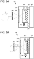
- FIGs. 2A and 2B are schematic cross-sectional views illustrating a configuration of an input device according to a first embodiment of the present invention.
- An input device 100 of the present embodiment includes a display unit 200 having a function of displaying an aerial image, and a detection unit 300 having a function of detecting a user operation related to the aerial image displayed by the display unit 200.
- the display unit 200 includes, for example, a light guide plate 220, a light source 230, a half mirror 240, and a retroreflective plate 250 in a rectangular housing 210 in which a space is formed.
- the light guide plate 220 is a transparent plate-like or film-like optical member including a flat upper surface, a flat bottom surface, and side surfaces connecting the upper surface and the bottom surface.
- a known plate can be used as the light guide plate 220, and may be made of, for example, glass, acrylic plastic, a polycarbonate resin, a cycloolefin-based resin, or the like.
- a light diffusion surface 222 is formed on the bottom or bottom surface of the light guide plate 220.
- the light diffusion surface 222 is formed, for example, by performing laser processing or printing processing on the bottom surface of the light guide plate 220.
- the light diffusion surface 222 forms a design that is an original image to generate the aerial image.
- the design is, for example, a number representing a floor number of an input button 12 as illustrated in Fig. 1 .
- the light source 230 is disposed on a side portion of the light guide plate 220.
- the light source 230 is not particularly limited, but, for example, a light emitting diode, a laser diode, or the like may be used.
- the light source 230 emits light having a constant emission angle (or radiation angle) toward the side portion of the light guide plate 220, and uniformly irradiates the inside of the light guide plate 220.
- the light diffusion surface 222 of the light guide plate 220 diffuses or scatters the incident light upward.
- the half mirror 240 is disposed on the upper surface side of the light guide plate 220.
- the half mirror 240 is a transparent optical member which separates incident light into reflected light and transmitted light.
- the half mirror 240 is configured by, for example, forming a dielectric multilayer film, an anti-reflection film, or the like on a front surface or a back surface of a substrate of such as flat glass or plastic.
- the half mirror 240 in which the amount of the reflected light and the amount of the transmitted light are equal is exemplified, but a beam splitter in which a ratio between the amount of reflected light and the amount of transmitted light differs depending on the luminance of the light source 230 or the luminance of the aerial image may be used.
- the retroreflective plate 250 is attached so as to be in contact with the bottom surface of the light guide plate 220.
- the retroreflective plate 250 is an optical member that reflects light in the same direction as the incident light and includes, for example, a prismatic retroreflective element such as a triangular pyramid retroreflective element and full cube corner retroreflective element, or beaded retroreflective element although its configuration is not particularly limited.
- the light incident from the side portion of the light guide plate 220 is diffused or scattered upward by the light diffusion surface 222, a part of the diffused or scattered light is reflected by the half mirror 240, and the reflected light thereof is incident on the retroreflective plate 250.
- the light incident on the retroreflective plate 250 is reflected in the same direction as the incident light, and a part thereof is transmitted through the half mirror 240 and forms an image again.
- an aerial image 260 floating from the display unit 200 is observed from the viewpoint of a user.
- the detection unit 300 is disposed on a bottom surface side of the display unit 200.
- the detection unit 300 detects the operation.
- the user visually recognizes the aerial image 260 displayed by the display unit 200 and presses the display unit 200 to perform input.
- the display unit 200 functions as an input button, and changes its position when being pressed by the user.
- the detection unit 300 detects a position change of the display unit 200 as the user operation.
- the detection unit 300 includes a switch whose contact is physically or mechanically opened and closed, and the contact of the switch is opened and closed by protrusions 310 in contact with a bottom surface of a housing 210 of the display unit 200.
- the protrusion 310 is elastically biased to the bottom surface of the housing by an elastic member such as a spring, and the switch is opened or closed, for example, when the display unit 200 is pressed against an elastic force thereof.
- a result of opening and closing of the switch is provided to a controller (not illustrated) or the like.
- Fig. 2A illustrates a state in which the aerial image 260 is displayed by the display unit 200 and the display unit 200 is not pressed by a user U. At this time, the protrusion 310 protrudes from the detection unit 300 and elastically biases the bottom surface of the housing 210.
- Fig. 2B illustrates a state in which the user visually recognizes the aerial image 260 and presses the display unit 200.
- the display unit 200 moves to the right, and the protrusion 310 is recessed inward by the movement, whereby the switch is opened and closed.
- the user U can know that the input has been confirmed by physically pressing the display unit 200.
- the display unit 200 that generates the aerial image is not limited to the configuration illustrated in Figs. 2A and 2B , and for example, the half mirror 240 may be changed to a polarization beam splitter, and a ⁇ /4 plate may be inserted between the light guide plate 220 and the retroreflective plate 250. As a result, the aerial image 260 can be displayed using polarized light.
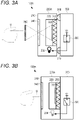
- Figs. 3A and 3B are views illustrating configurations of an input device 100A according to the second embodiment, and the same configurations as those in Figs. 2A and 2B are denoted by the same reference signs.
- a detection unit 300 provides a detection result of a user operation to a display unit 200A, and the display unit 200A switches on and off of a light source 230 according to the detection result.
- the detection unit 300 includes a switch 320 that is opened and closed depending on positions of protrusions 310, which is similar to the first embodiment.
- the switch 320 is configured to be closed when the display unit 200A is not pressed by a user U as illustrated in Fig. 3A , and to be opened when the display unit 200A is pressed by the user U as illustrated in Fig. 3B .
- the switch 320 provides a voltage signal Vd to the display unit 200A when the switch 320 is closed, and provides a signal at the GND level to the display unit 200A when the switch 320 is opened.
- the protrusions 310 may be made of a conductive material, and signals indicating opening and closing of the switch 320 may be provided to the display unit 200A using one of the protrusions 310 as a part of a current path.
- the display unit 200A When the display unit 200A is not pressed by the user U as illustrated in Fig. 3A , the display unit 200A turns on the light source 230 based on the voltage signal Vd to display an aerial image 260. On the other hand, when the display unit 200A is pressed by the user U as illustrated in Fig. 3B , the display unit 200A turns off the light source 230 based on the signal at the GND level not to display the aerial image 260. Since the aerial image 260 is not displayed in synchronization with the pressing of the display unit 200A, the user can visually recognize that the input has been confirmed.
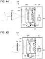
- FIGS. 4A and 4B are views illustrating configurations of an input device 100B according to the third embodiment, and the same configurations as those in Figs. 2A to 3B are denoted by the same reference signs.
- a display unit 200B of the present embodiment includes two stacked light guide plates 220 and 220A.
- the two light guide plates 220 and 220A may have the same configuration, or designs of light diffusion surfaces 222 and 222A may be different from each other.
- two light sources 230 and 230A are provided so as to correspond to the two light guide plates 220 and 220A.
- the two light sources 230 and 230A may have the same configuration or may emit beams of light of different wavelengths (colors), respectively.
- the light guide plate 220A is disposed on a bottom surface side of the light guide plate 220, and a retroreflective plate 250 is disposed on a bottom surface side of the light guide plate 220A.
- the display unit 200B turns on any one of the light sources 230 and 230A, thereby displaying aerial images 260 and 260A by any one of the light guide plates 220 and 220A.
- the display unit 200B turns off the light source 230 and turns on the light source 230A to irradiate the light guide plate 220A as illustrated in Fig. 4A .
- Light diffused or scattered by the light diffusion surface 222A of the light guide plate 220A is transmitted through the light guide plate 220, is partially reflected by a half mirror 240, and the reflected light thereof enters the retroreflective plate 250 via the light guide plates 220 and 220A.
- the retroreflective plate 250 reflects light in the same direction as the incident light, the reflected light thereof is transmitted through the light guide plates 220A and 220, and a part of the transmitted light is transmitted through the half mirror 240.
- the aerial image 260A using the light guide plate 220A is displayed.
- the aerial image 260A is generated at a line-symmetric position with respect to the half mirror 240, and thus, the aerial image 260A is displayed so as to float relatively high from the display unit 200B.
- a detection unit 300 When a user U visually recognizes the aerial image 260A and presses the display unit 200B as a user operation, such pressing is detected by a detection unit 300, and a detection result is provided to the display unit 200B. A state at this time is illustrated in Fig. 4B .
- the display unit 200B turns on the light source 230 and turns off the light source 230A to irradiate the light guide plate 220. Light diffused or scattered by the light diffusion surface 222 of the light guide plate 220 is partially reflected by the half mirror 240, and the reflected light thereof enters the retroreflective plate 250 via the light guide plates 220 and 220A.
- the retroreflective plate 250 reflects light in the same direction as the incident light, the reflected light thereof is transmitted through the light guide plates 220A and 220, and a part of the transmitted light is transmitted through the half mirror 240. In this manner, the aerial image 260 using the light guide plate 220 is displayed.
- the aerial image 260 has a lower floating height than the aerial image 260A.
- the user can know input confirmation by visually recognizing that a display position of the aerial image changes in synchronization with the user operation according to the present embodiment.
- a size or a shape of the light diffusion surface 222 of the light guide plate 220 may be different from that of the light diffusion surface 222A of the light guide plate 220A.
- the user can know the input confirmation based on a change in size or shape of the aerial image 260.
- colors of the light source 230 and the light source 230A may be changed. In this case, the user can know the input confirmation based on a change in color of the aerial image 260.
- FIGS. 5A and 5B are views illustrating configurations of an input device 100C according to the fourth embodiment, and the same configurations as those in Figs. 2A to 3B are denoted by the same reference signs.
- a display unit 200C of the present embodiment includes an electron lens 270 in front of a half mirror 240 in addition to the configurations of the display unit 200A of the second embodiment.
- the electron lens 270 is a concave lens or a convex lens whose focal length can be electrically changed.
- the electron lens 270 is configured using a liquid crystal lens.
- a protective glass or the like may be disposed on the surface of the electron lens 270 in order to protect the electron lens 270 from a user operation.
- a detection unit 300 detects pressing of the display unit 200C and provides a detection result to the display unit 200C, which is similar to the above-described embodiments.
- the display unit 200C changes the focal length of the electron lens 270 depending on the detection result, thereby changing a display position (hover height) and a dimension (size) of an aerial image.
- Fig. 5A illustrates a state in which pressing by a user U is not performed.
- the display unit 200C adjusts the focal length of the electron lens 270, and causes an aerial image 260 to be displayed so as to float relatively far from the display unit 200C.
- Fig. 5B illustrates a state in which the pressing by the user U is performed.
- the display unit 200C adjusts the focal length of the electron lens 270 such that an aerial image 260C is displayed at a position relatively close to the display unit 200C with a small size in response to the detection of the pressing of the display unit 200C by the detection unit 300.
- the user can know input confirmation by visually recognizing that changes in the hover height and the size of the aerial image in synchronization with the user operation according to the present embodiment.
- the detection unit 300 is not necessarily limited to such a switch and may be a switch having another configuration.
- a switch 320 as a detection unit 300 may be built in a housing 210 of a display unit 200D, and protrusions 310 may protrude from a bottom surface of the housing 210. In this case, the protrusions 310 protrude to open the switch 320 when the display unit 200D is not pressed as illustrated in Fig.
- an input device 100D can be further reduced in thickness.
- a spatial input device of the present example can be applied to any user input, and can be applied to, for example, a computer device, an in-vehicle electronic device, an ATM of a bank or the like, a ticket purchasing machine of a station or the like, an input button of an elevator, and the like.
Landscapes
- Engineering & Computer Science (AREA)
- Physics & Mathematics (AREA)
- General Physics & Mathematics (AREA)
- General Engineering & Computer Science (AREA)
- Theoretical Computer Science (AREA)
- Automation & Control Theory (AREA)
- Optics & Photonics (AREA)
- Human Computer Interaction (AREA)
- Computer Networks & Wireless Communication (AREA)
- Stereoscopic And Panoramic Photography (AREA)
- Illuminated Signs And Luminous Advertising (AREA)
- Switch Cases, Indication, And Locking (AREA)
- Push-Button Switches (AREA)
- Position Input By Displaying (AREA)
- Switches Operated By Changes In Physical Conditions (AREA)
Abstract
Description
- The present invention relates to an input device, and particularly to an input device capable of performing an input operation by displaying an aerial image by retro-reflection.
- Aerial imaging by retro-reflection (AIRR) is known (for example,
JP 2017-107165 A JP 2018-81138 A JP 2019-101055 A JP 2019-101055 A - Non-contact buttons have been rapidly expanded as input functions required for elevators and the like.
Fig. 1 is an example of aninput device 10 provided in an elevator, andbuttons 12 configured to input floor numbers andbuttons 14 configured to input opening and closing of a door are mounted. Thebuttons buttons aerial image 16 is displayed above thebuttons aerial image 16. - In a case where an input operation of the user is detected by the non-contact sensor, the user can perform the input in a non-contact manner, but there is a problem that it is difficult to know whether or not the input has been confirmed when the user places the hand on the
aerial image 16. In addition, in a case where the aerial image of the button is displayed, it is required to achieve a reduction in thickness of the input device. - An object of the present invention is to provide an input device capable of notifying input confirmation and achieving a reduction in thickness.
- The invention relates to an input device according to the appended claims. Embodiments are disclosed in the dependent claims.
- According to an aspect, an input device according to the present invention includes: a display unit that includes a light guide plate disposed between a beam splitter and a retroreflective member and a light source irradiating the light guide plate, and displays an aerial image of a light diffusion surface formed on the light guide plate in response to incident light; and a detection unit that detects a user operation related to the aerial image, and the display unit switches on and off of the light source based on a detection result of the detection unit.
- In an embodiment, the detection unit detects pressing of the display unit as the user operation. In an embodiment, the detection unit includes an open/close switch to detect the pressing of the display unit. In an embodiment, when the user operation is detected, the display unit turns off the light source and causes the aerial image not to be displayed. In an embodiment, the light guide plate includes first and second light guide plates which are stacked, and the light source includes first and second light sources respectively corresponding to the first and second light guide plates, and the display unit turns on one of the first and second light sources and turns off another of the first and second light sources based on the detection result of the detection unit. In an embodiment, the second light guide plate is farther from the beam splitter than the first light guide plate, and the display unit turns off the first light source and turns on the second light source to display a second aerial image, and, when a user operation related to the second aerial image using the second light guide plate is detected, turns off the second light source and turns on the first light source to displays a first aerial image using the first light guide plate. In an embodiment, the first aerial image using the first light guide plate is smaller than the second aerial image using the second light guide plate. In an embodiment, a color of light emitted from the first light source is different from a color of light emitted from the second light source. In an embodiment, the display unit further includes a lens whose focal length is electrically changeable, and the display unit changes the focal length of the lens based on the detection result of the detection unit. In an embodiment, the display unit changes a size or a display position of the aerial image when the user operation is detected.
- According to the present invention, the display unit switches on and off of the light source based on the detection result of the detection unit, and thus, the user can know the input confirmation through the display of the aerial image. In addition, it is possible to achieve the reduction in the thickness of the input device by detecting pressing of the display unit.
-
Fig. 1 is a view illustrating an example of an input device mounted on a conventional elevator. -
Figs. 2A and 2B are schematic cross-sectional views illustrating configurations of an input device according to a first embodiment of the present invention. -
Figs. 3A and 3B are schematic cross-sectional views illustrating configurations of an input device according to a second embodiment of the present invention. -
Figs. 4A and 4B are schematic cross-sectional views illustrating configurations of an input device according to a third embodiment of the present invention. -
Figs. 5A and 5B are schematic cross-sectional views illustrating configurations of an input device according to a fourth embodiment of the present invention. -
Figs. 6A and 6B are schematic cross-sectional views illustrating configurations of an input device according to a modification of the present invention. - Next, embodiments of the present invention will be described. An input device according to aspects of the present invention is an input device in which a function of displaying an aerial image using retro-reflection and a function of detecting a user operation are integrated. It should be noted that the drawings referred to in the following description of the embodiments include exaggerated display in order to facilitate understanding of the invention, and do not directly represent the shape and scale of an actual product.
- Next, an embodiment of the present invention will be described in detail.
Figs. 2A and 2B are schematic cross-sectional views illustrating a configuration of an input device according to a first embodiment of the present invention. Aninput device 100 of the present embodiment includes adisplay unit 200 having a function of displaying an aerial image, and adetection unit 300 having a function of detecting a user operation related to the aerial image displayed by thedisplay unit 200. - The
display unit 200 includes, for example, alight guide plate 220, alight source 230, ahalf mirror 240, and aretroreflective plate 250 in arectangular housing 210 in which a space is formed. - The
light guide plate 220 is a transparent plate-like or film-like optical member including a flat upper surface, a flat bottom surface, and side surfaces connecting the upper surface and the bottom surface. A known plate can be used as thelight guide plate 220, and may be made of, for example, glass, acrylic plastic, a polycarbonate resin, a cycloolefin-based resin, or the like. Alight diffusion surface 222 is formed on the bottom or bottom surface of thelight guide plate 220. Thelight diffusion surface 222 is formed, for example, by performing laser processing or printing processing on the bottom surface of thelight guide plate 220. Thelight diffusion surface 222 forms a design that is an original image to generate the aerial image. The design is, for example, a number representing a floor number of aninput button 12 as illustrated inFig. 1 . - The
light source 230 is disposed on a side portion of thelight guide plate 220. Thelight source 230 is not particularly limited, but, for example, a light emitting diode, a laser diode, or the like may be used. Thelight source 230 emits light having a constant emission angle (or radiation angle) toward the side portion of thelight guide plate 220, and uniformly irradiates the inside of thelight guide plate 220. Thelight diffusion surface 222 of thelight guide plate 220 diffuses or scatters the incident light upward. - The
half mirror 240 is disposed on the upper surface side of thelight guide plate 220. Thehalf mirror 240 is a transparent optical member which separates incident light into reflected light and transmitted light. Thehalf mirror 240 is configured by, for example, forming a dielectric multilayer film, an anti-reflection film, or the like on a front surface or a back surface of a substrate of such as flat glass or plastic. Here, thehalf mirror 240 in which the amount of the reflected light and the amount of the transmitted light are equal is exemplified, but a beam splitter in which a ratio between the amount of reflected light and the amount of transmitted light differs depending on the luminance of thelight source 230 or the luminance of the aerial image may be used. - The
retroreflective plate 250 is attached so as to be in contact with the bottom surface of thelight guide plate 220. Theretroreflective plate 250 is an optical member that reflects light in the same direction as the incident light and includes, for example, a prismatic retroreflective element such as a triangular pyramid retroreflective element and full cube corner retroreflective element, or beaded retroreflective element although its configuration is not particularly limited. - The light incident from the side portion of the
light guide plate 220 is diffused or scattered upward by thelight diffusion surface 222, a part of the diffused or scattered light is reflected by thehalf mirror 240, and the reflected light thereof is incident on theretroreflective plate 250. The light incident on theretroreflective plate 250 is reflected in the same direction as the incident light, and a part thereof is transmitted through thehalf mirror 240 and forms an image again. As a result, anaerial image 260 floating from thedisplay unit 200 is observed from the viewpoint of a user. - The
detection unit 300 is disposed on a bottom surface side of thedisplay unit 200. When thedisplay unit 200 is operated by the user, thedetection unit 300 detects the operation. In an aspect, the user visually recognizes theaerial image 260 displayed by thedisplay unit 200 and presses thedisplay unit 200 to perform input. Thedisplay unit 200 functions as an input button, and changes its position when being pressed by the user. Thedetection unit 300 detects a position change of thedisplay unit 200 as the user operation. - As a specific example, the
detection unit 300 includes a switch whose contact is physically or mechanically opened and closed, and the contact of the switch is opened and closed byprotrusions 310 in contact with a bottom surface of ahousing 210 of thedisplay unit 200. Theprotrusion 310 is elastically biased to the bottom surface of the housing by an elastic member such as a spring, and the switch is opened or closed, for example, when thedisplay unit 200 is pressed against an elastic force thereof. A result of opening and closing of the switch is provided to a controller (not illustrated) or the like. -
Fig. 2A illustrates a state in which theaerial image 260 is displayed by thedisplay unit 200 and thedisplay unit 200 is not pressed by a user U. At this time, theprotrusion 310 protrudes from thedetection unit 300 and elastically biases the bottom surface of thehousing 210. -
Fig. 2B illustrates a state in which the user visually recognizes theaerial image 260 and presses thedisplay unit 200. When the user U presses thedisplay unit 200, thedisplay unit 200 moves to the right, and theprotrusion 310 is recessed inward by the movement, whereby the switch is opened and closed. - In this manner, it is possible to reduce the thickness of the
input device 100 by integrating thedisplay unit 200 and thedetection unit 300 while securing the state in which thedisplay unit 200 can be pressed by visually recognizing theaerial image 260 in theinput device 100 of the present embodiment. In addition, the user U can know that the input has been confirmed by physically pressing thedisplay unit 200. - Note that the
display unit 200 that generates the aerial image is not limited to the configuration illustrated inFigs. 2A and 2B , and for example, thehalf mirror 240 may be changed to a polarization beam splitter, and a λ/4 plate may be inserted between thelight guide plate 220 and theretroreflective plate 250. As a result, theaerial image 260 can be displayed using polarized light. - Next, a second embodiment of the present invention will be described.
Figs. 3A and 3B are views illustrating configurations of aninput device 100A according to the second embodiment, and the same configurations as those inFigs. 2A and 2B are denoted by the same reference signs. In the present embodiment, adetection unit 300 provides a detection result of a user operation to adisplay unit 200A, and thedisplay unit 200A switches on and off of alight source 230 according to the detection result. - The
detection unit 300 includes aswitch 320 that is opened and closed depending on positions ofprotrusions 310, which is similar to the first embodiment. For example, theswitch 320 is configured to be closed when thedisplay unit 200A is not pressed by a user U as illustrated inFig. 3A , and to be opened when thedisplay unit 200A is pressed by the user U as illustrated inFig. 3B . Theswitch 320 provides a voltage signal Vd to thedisplay unit 200A when theswitch 320 is closed, and provides a signal at the GND level to thedisplay unit 200A when theswitch 320 is opened. In one example, theprotrusions 310 may be made of a conductive material, and signals indicating opening and closing of theswitch 320 may be provided to thedisplay unit 200A using one of theprotrusions 310 as a part of a current path. - When the
display unit 200A is not pressed by the user U as illustrated inFig. 3A , thedisplay unit 200A turns on thelight source 230 based on the voltage signal Vd to display anaerial image 260. On the other hand, when thedisplay unit 200A is pressed by the user U as illustrated inFig. 3B , thedisplay unit 200A turns off thelight source 230 based on the signal at the GND level not to display theaerial image 260. Since theaerial image 260 is not displayed in synchronization with the pressing of thedisplay unit 200A, the user can visually recognize that the input has been confirmed. - In this manner, it is possible to notify the user of the input confirmation by switching on and off of the
light source 230 depending on the detection result of the user operation to perform display and non-display of theaerial image 260 according to the present embodiment. In addition, it is possible to achieve a reduction in thickness of the input device since the pressing of thedisplay unit 200A is detected (the amount of pressing may be small). - Next, a third embodiment of the present invention will be described.
Figs. 4A and 4B are views illustrating configurations of aninput device 100B according to the third embodiment, and the same configurations as those inFigs. 2A to 3B are denoted by the same reference signs. - A
display unit 200B of the present embodiment includes two stackedlight guide plates light guide plates light sources light guide plates light sources - The
light guide plate 220A is disposed on a bottom surface side of thelight guide plate 220, and aretroreflective plate 250 is disposed on a bottom surface side of thelight guide plate 220A. Thedisplay unit 200B turns on any one of thelight sources aerial images light guide plates display unit 200B turns off thelight source 230 and turns on thelight source 230A to irradiate thelight guide plate 220A as illustrated inFig. 4A . Light diffused or scattered by thelight diffusion surface 222A of thelight guide plate 220A is transmitted through thelight guide plate 220, is partially reflected by ahalf mirror 240, and the reflected light thereof enters theretroreflective plate 250 via thelight guide plates retroreflective plate 250 reflects light in the same direction as the incident light, the reflected light thereof is transmitted through thelight guide plates half mirror 240. In this manner, theaerial image 260A using thelight guide plate 220A is displayed. Theaerial image 260A is generated at a line-symmetric position with respect to thehalf mirror 240, and thus, theaerial image 260A is displayed so as to float relatively high from thedisplay unit 200B. - When a user U visually recognizes the
aerial image 260A and presses thedisplay unit 200B as a user operation, such pressing is detected by adetection unit 300, and a detection result is provided to thedisplay unit 200B. A state at this time is illustrated inFig. 4B . When the pressing of the user is detected by thedetection unit 300, thedisplay unit 200B turns on thelight source 230 and turns off thelight source 230A to irradiate thelight guide plate 220. Light diffused or scattered by thelight diffusion surface 222 of thelight guide plate 220 is partially reflected by thehalf mirror 240, and the reflected light thereof enters theretroreflective plate 250 via thelight guide plates retroreflective plate 250 reflects light in the same direction as the incident light, the reflected light thereof is transmitted through thelight guide plates half mirror 240. In this manner, theaerial image 260 using thelight guide plate 220 is displayed. Theaerial image 260 has a lower floating height than theaerial image 260A. - In this manner, the user can know input confirmation by visually recognizing that a display position of the aerial image changes in synchronization with the user operation according to the present embodiment. Note that a size or a shape of the
light diffusion surface 222 of thelight guide plate 220 may be different from that of thelight diffusion surface 222A of thelight guide plate 220A. In this case, the user can know the input confirmation based on a change in size or shape of theaerial image 260. Furthermore, colors of thelight source 230 and thelight source 230A may be changed. In this case, the user can know the input confirmation based on a change in color of theaerial image 260. - Next, a fourth embodiment of the present invention will be described.
Figs. 5A and 5B are views illustrating configurations of aninput device 100C according to the fourth embodiment, and the same configurations as those inFigs. 2A to 3B are denoted by the same reference signs. Adisplay unit 200C of the present embodiment includes anelectron lens 270 in front of ahalf mirror 240 in addition to the configurations of thedisplay unit 200A of the second embodiment. Theelectron lens 270 is a concave lens or a convex lens whose focal length can be electrically changed. For example, theelectron lens 270 is configured using a liquid crystal lens. In addition, a protective glass or the like may be disposed on the surface of theelectron lens 270 in order to protect theelectron lens 270 from a user operation. - A
detection unit 300 detects pressing of thedisplay unit 200C and provides a detection result to thedisplay unit 200C, which is similar to the above-described embodiments. Thedisplay unit 200C changes the focal length of theelectron lens 270 depending on the detection result, thereby changing a display position (hover height) and a dimension (size) of an aerial image. -
Fig. 5A illustrates a state in which pressing by a user U is not performed. At this time, thedisplay unit 200C adjusts the focal length of theelectron lens 270, and causes anaerial image 260 to be displayed so as to float relatively far from thedisplay unit 200C. -
Fig. 5B illustrates a state in which the pressing by the user U is performed. Thedisplay unit 200C adjusts the focal length of theelectron lens 270 such that anaerial image 260C is displayed at a position relatively close to thedisplay unit 200C with a small size in response to the detection of the pressing of thedisplay unit 200C by thedetection unit 300. - In this manner, the user can know input confirmation by visually recognizing that changes in the hover height and the size of the aerial image in synchronization with the user operation according to the present embodiment.
- Although the
switch 320 whose contact is opened and closed by the movement of theprotrusions 310 is exemplified as thedetection unit 300 in the above-described embodiments, thedetection unit 300 is not necessarily limited to such a switch and may be a switch having another configuration. For example, as illustrated inFig. 6A , aswitch 320 as adetection unit 300 may be built in ahousing 210 of adisplay unit 200D, andprotrusions 310 may protrude from a bottom surface of thehousing 210. In this case, theprotrusions 310 protrude to open theswitch 320 when thedisplay unit 200D is not pressed as illustrated inFig. 6A , and theprotrusions 310 come into contact with astationary member 330 and are recessed to close theswitch 320 when thedisplay unit 200D is pressed as illustrated inFig. 6B . Thedisplay unit 200D switches on and off of alight source 230 depending on the opening and closing of theswitch 320. With such a configuration, aninput device 100D can be further reduced in thickness. - A spatial input device of the present example can be applied to any user input, and can be applied to, for example, a computer device, an in-vehicle electronic device, an ATM of a bank or the like, a ticket purchasing machine of a station or the like, an input button of an elevator, and the like.
- Although the preferred embodiments of the present invention have been described in detail above, the present invention is not limited to the specific embodiments, and various modifications and changes can be made within the scope of the gist of the invention set forth in the claims.
-
- 100, 100A, 100B, 100C input device
- 200, 200A, 200B, 200C display unit
- 210 housing
- 220, 220A light guide plate
- 222, 222A light diffusion surface
- 230, 230A light source
- 240 half mirror
- 250 retroreflective plate
- 260, 260A aerial image
- 270 electron lens
- 300 detection unit
- 310 protrusion
- 320 switch
Claims (10)
- An input device (100) comprising:a display unit (200) including a light guide plate (220) disposed between a beam splitter (240) and a retroreflective member (250) and a light source (230) irradiating the light guide plate (220), and configured to display an aerial image (260) of a light diffusion surface (222) formed on the light guide plate (220) in response to incident light; anda detection unit (300) configured to detect a user operation related to the aerial image (260), whereinthe display unit (200) is configured to switch on and off of the light source (230) based on a detection result of the detection unit (300).
- The input device (100) according to claim 1, wherein
the detection unit (300) is configured to detect pressing of the display unit (200) as the user operation. - The input device (100) according to claim 2, wherein
the detection unit (300) includes an open/close switch (320) to detect the pressing of the display unit (200). - The input device (100A) according to any one of claims 1 to 3, wherein
the display unit (200A) is configured to turn off the light source (230) not to display the aerial image (260) when the user operation is detected. - The input device (100B) according to any one of claims 1 to 4, whereinthe light guide plate includes first and second light guide plates (220, 220A) which are stacked, and the light source includes first and second light sources (230, 230A) respectively corresponding to the first and second light guide plates (220, 220A), andthe display unit (200B) is configured to turn on one of the first and second light sources (230, 230A) and turn off another of the first and second light sources (230, 230A) based on the detection result of the detection unit (300).
- The input device (100B) according to claim 5, whereinthe second light guide plate (220A) is farther from the beam splitter (240) than the first light guide plate (220), andthe display unit (200B) is configured to turn off the first light source (230) and turn on the second light source (230A) to display a second aerial image (260A), and, when a user operation related to the second aerial image (260A) using the second light guide plate (220A) is detected, to turn off the second light source (230A) and turn on the first light source (230) to display a first aerial image (260) using the first light guide plate (220).
- The input device (100B) according to claim 6, wherein
the first aerial image (260) using the first light guide plate (220) is smaller than the second aerial image (260A) using the second light guide plate (220A). - The input device (100B) according to claim 6 or 7, wherein
a color of light emitted from the first light source (230) is different from a color of light emitted from the second light source (230A). - The input device (100C) according to any one of claims 1 to 8, whereinthe display unit (200C) further includes a lens (270) whose focal length is electrically changeable, andthe display unit (200C) is configured to change the focal length of the lens (270) based on the detection result of the detection unit (300).
- The input device (100C) according to claim 9, wherein
the display unit (200C) is configured to change a size or a display position of the aerial image (260) when the user operation is detected.
Applications Claiming Priority (1)
| Application Number | Priority Date | Filing Date | Title |
|---|---|---|---|
| JP2021083615A JP7706832B2 (en) | 2021-05-18 | 2021-05-18 | Input Devices |
Publications (2)
| Publication Number | Publication Date |
|---|---|
| EP4092517A1 true EP4092517A1 (en) | 2022-11-23 |
| EP4092517B1 EP4092517B1 (en) | 2025-07-16 |
Family
ID=81854699
Family Applications (1)
| Application Number | Title | Priority Date | Filing Date |
|---|---|---|---|
| EP22172270.5A Active EP4092517B1 (en) | 2021-05-18 | 2022-05-09 | Input device |
Country Status (4)
| Country | Link |
|---|---|
| US (1) | US12033816B2 (en) |
| EP (1) | EP4092517B1 (en) |
| JP (1) | JP7706832B2 (en) |
| CN (1) | CN115367577A (en) |
Cited By (1)
| Publication number | Priority date | Publication date | Assignee | Title |
|---|---|---|---|---|
| EP4071526B1 (en) * | 2021-03-26 | 2025-01-08 | Alps Alpine Co., Ltd. | Display device |
Families Citing this family (5)
| Publication number | Priority date | Publication date | Assignee | Title |
|---|---|---|---|---|
| JP7362881B1 (en) | 2022-12-13 | 2023-10-17 | 東芝エレベータ株式会社 | Elevator information system and elevator equipment |
| JP2024111912A (en) | 2023-02-07 | 2024-08-20 | アルプスアルパイン株式会社 | Input display device |
| WO2024209624A1 (en) * | 2023-04-06 | 2024-10-10 | 三菱電機ビルソリューションズ株式会社 | Button display device and call registration system |
| WO2024209626A1 (en) * | 2023-04-06 | 2024-10-10 | 三菱電機ビルソリューションズ株式会社 | Elevator system and button display device |
| JP2025001182A (en) * | 2023-06-20 | 2025-01-08 | アルプスアルパイン株式会社 | Display device |
Citations (7)
| Publication number | Priority date | Publication date | Assignee | Title |
|---|---|---|---|---|
| JP2017107165A (en) | 2015-12-07 | 2017-06-15 | 国立大学法人宇都宮大学 | Display device and display method of aerial image |
| US20170192244A1 (en) * | 2014-10-06 | 2017-07-06 | Omron Corporation | Optical device |
| WO2018078777A1 (en) * | 2016-10-27 | 2018-05-03 | マクセル株式会社 | Aerial image display system, wavelength-selective image-forming device, image display device, aerial image display method |
| JP2018081138A (en) | 2016-11-14 | 2018-05-24 | 日本カーバイド工業株式会社 | Image display unit |
| JP2019101055A (en) | 2017-11-28 | 2019-06-24 | コニカミノルタ株式会社 | Aerial video display device |
| WO2020012711A1 (en) * | 2018-07-10 | 2020-01-16 | オムロン株式会社 | Input device |
| WO2020075456A1 (en) * | 2018-10-11 | 2020-04-16 | オムロン株式会社 | Input device |
Family Cites Families (14)
| Publication number | Priority date | Publication date | Assignee | Title |
|---|---|---|---|---|
| JP3105262U (en) | 2004-05-17 | 2004-10-21 | 株式会社シルバーテック | Mirror device |
| JP4929636B2 (en) | 2005-07-15 | 2012-05-09 | カシオ計算機株式会社 | Liquid crystal display |
| CN103299358B (en) * | 2011-11-28 | 2016-10-05 | 松下知识产权经营株式会社 | Display device |
| JP2015151253A (en) | 2014-02-18 | 2015-08-24 | 三菱電機ビルテクノサービス株式会社 | Operation panel device of elevator |
| JP2016095634A (en) * | 2014-11-13 | 2016-05-26 | パナソニックヘルスケアホールディングス株式会社 | Midair touch panel and surgery simulator display system having the same |
| JP6558166B2 (en) * | 2015-01-13 | 2019-08-14 | オムロン株式会社 | Optical device and operation input device |
| JP6760728B2 (en) | 2015-12-03 | 2020-09-23 | 株式会社エス・ケー・ジー | Light emitting device |
| WO2017099116A1 (en) | 2015-12-07 | 2017-06-15 | 国立大学法人宇都宮大学 | Display device, and display method for aerial image |
| JP2020056806A (en) | 2017-02-10 | 2020-04-09 | パナソニックIpマネジメント株式会社 | Control device |
| JPWO2019039600A1 (en) | 2017-08-25 | 2020-07-30 | 林テレンプ株式会社 | Aerial image display device |
| JP7134011B2 (en) * | 2018-08-07 | 2022-09-09 | コイト電工株式会社 | SPATIAL PROJECTION DEVICE AND NON-CONTACT INPUT DEVICE INCLUDING THE SAME |
| JP7572145B2 (en) | 2018-10-11 | 2024-10-23 | オムロン株式会社 | Input Devices |
| JP7480491B2 (en) | 2018-10-19 | 2024-05-10 | オムロン株式会社 | Display device |
| JP2022139533A (en) | 2021-03-12 | 2022-09-26 | ミネベアミツミ株式会社 | Aerial display device |
-
2021
- 2021-05-18 JP JP2021083615A patent/JP7706832B2/en active Active
-
2022
- 2022-05-09 EP EP22172270.5A patent/EP4092517B1/en active Active
- 2022-05-11 US US17/741,850 patent/US12033816B2/en active Active
- 2022-05-17 CN CN202210538639.XA patent/CN115367577A/en active Pending
Patent Citations (7)
| Publication number | Priority date | Publication date | Assignee | Title |
|---|---|---|---|---|
| US20170192244A1 (en) * | 2014-10-06 | 2017-07-06 | Omron Corporation | Optical device |
| JP2017107165A (en) | 2015-12-07 | 2017-06-15 | 国立大学法人宇都宮大学 | Display device and display method of aerial image |
| WO2018078777A1 (en) * | 2016-10-27 | 2018-05-03 | マクセル株式会社 | Aerial image display system, wavelength-selective image-forming device, image display device, aerial image display method |
| JP2018081138A (en) | 2016-11-14 | 2018-05-24 | 日本カーバイド工業株式会社 | Image display unit |
| JP2019101055A (en) | 2017-11-28 | 2019-06-24 | コニカミノルタ株式会社 | Aerial video display device |
| WO2020012711A1 (en) * | 2018-07-10 | 2020-01-16 | オムロン株式会社 | Input device |
| WO2020075456A1 (en) * | 2018-10-11 | 2020-04-16 | オムロン株式会社 | Input device |
Cited By (1)
| Publication number | Priority date | Publication date | Assignee | Title |
|---|---|---|---|---|
| EP4071526B1 (en) * | 2021-03-26 | 2025-01-08 | Alps Alpine Co., Ltd. | Display device |
Also Published As
| Publication number | Publication date |
|---|---|
| EP4092517B1 (en) | 2025-07-16 |
| US12033816B2 (en) | 2024-07-09 |
| US20220375699A1 (en) | 2022-11-24 |
| JP7706832B2 (en) | 2025-07-14 |
| CN115367577A (en) | 2022-11-22 |
| JP2022177400A (en) | 2022-12-01 |
Similar Documents
| Publication | Publication Date | Title |
|---|---|---|
| EP4092517B1 (en) | Input device | |
| JP6553155B2 (en) | Flat panel display with built-in optical image recognition sensor | |
| US8920016B2 (en) | Display member and display device | |
| US12566524B2 (en) | Input device | |
| EP4134730B1 (en) | Display device and spatial input device including the same | |
| US20160179212A1 (en) | Keyboard with improved reliability | |
| CN211427365U (en) | Optical detection device and electronic apparatus | |
| US20110067989A1 (en) | Button structure with light transmittance and related electronic device | |
| TWI790921B (en) | Keyswitch assembly | |
| TWI308733B (en) | Control panel device and display | |
| US12025815B2 (en) | Display device including first and second display panels | |
| CA2792806C (en) | Touch tracking optical input device | |
| JP2024152592A (en) | button | |
| EP4403965A1 (en) | Aerial image display apparatus | |
| JP2023018255A (en) | Push-button switch | |
| EP4722870A1 (en) | Aerial input apparatus | |
| JP4676397B2 (en) | Switch device | |
| US20140332358A1 (en) | Operation key and switching unit | |
| US20250164819A1 (en) | Display device | |
| US20250044612A1 (en) | Image display device | |
| EP4560366A1 (en) | Display device | |
| TWM577170U (en) | Keyboard button | |
| KR20260001369A (en) | Aerial image display device | |
| JP2023091120A (en) | Pushbutton switch unit | |
| JP2013229164A (en) | Sensor device |
Legal Events
| Date | Code | Title | Description |
|---|---|---|---|
| PUAI | Public reference made under article 153(3) epc to a published international application that has entered the european phase |
Free format text: ORIGINAL CODE: 0009012 |
|
| STAA | Information on the status of an ep patent application or granted ep patent |
Free format text: STATUS: THE APPLICATION HAS BEEN PUBLISHED |
|
| AK | Designated contracting states |
Kind code of ref document: A1 Designated state(s): AL AT BE BG CH CY CZ DE DK EE ES FI FR GB GR HR HU IE IS IT LI LT LU LV MC MK MT NL NO PL PT RO RS SE SI SK SM TR |
|
| STAA | Information on the status of an ep patent application or granted ep patent |
Free format text: STATUS: REQUEST FOR EXAMINATION WAS MADE |
|
| 17P | Request for examination filed |
Effective date: 20230517 |
|
| RBV | Designated contracting states (corrected) |
Designated state(s): AL AT BE BG CH CY CZ DE DK EE ES FI FR GB GR HR HU IE IS IT LI LT LU LV MC MK MT NL NO PL PT RO RS SE SI SK SM TR |
|
| GRAP | Despatch of communication of intention to grant a patent |
Free format text: ORIGINAL CODE: EPIDOSNIGR1 |
|
| STAA | Information on the status of an ep patent application or granted ep patent |
Free format text: STATUS: GRANT OF PATENT IS INTENDED |
|
| RIC1 | Information provided on ipc code assigned before grant |
Ipc: G02B 30/56 20200101ALN20250212BHEP Ipc: G06F 3/04886 20220101AFI20250212BHEP |
|
| INTG | Intention to grant announced |
Effective date: 20250226 |
|
| GRAS | Grant fee paid |
Free format text: ORIGINAL CODE: EPIDOSNIGR3 |
|
| GRAA | (expected) grant |
Free format text: ORIGINAL CODE: 0009210 |
|
| STAA | Information on the status of an ep patent application or granted ep patent |
Free format text: STATUS: THE PATENT HAS BEEN GRANTED |
|
| AK | Designated contracting states |
Kind code of ref document: B1 Designated state(s): AL AT BE BG CH CY CZ DE DK EE ES FI FR GB GR HR HU IE IS IT LI LT LU LV MC MK MT NL NO PL PT RO RS SE SI SK SM TR |
|
| P01 | Opt-out of the competence of the unified patent court (upc) registered |
Free format text: CASE NUMBER: APP_27436/2025 Effective date: 20250610 |
|
| REG | Reference to a national code |
Ref country code: GB Ref legal event code: FG4D |
|
| REG | Reference to a national code |
Ref country code: CH Ref legal event code: EP |
|
| REG | Reference to a national code |
Ref country code: DE Ref legal event code: R096 Ref document number: 602022017535 Country of ref document: DE |
|
| REG | Reference to a national code |
Ref country code: IE Ref legal event code: FG4D |
|
| REG | Reference to a national code |
Ref country code: NL Ref legal event code: MP Effective date: 20250716 |
|
| PG25 | Lapsed in a contracting state [announced via postgrant information from national office to epo] |
Ref country code: PT Free format text: LAPSE BECAUSE OF FAILURE TO SUBMIT A TRANSLATION OF THE DESCRIPTION OR TO PAY THE FEE WITHIN THE PRESCRIBED TIME-LIMIT Effective date: 20251117 |
|
| PG25 | Lapsed in a contracting state [announced via postgrant information from national office to epo] |
Ref country code: NL Free format text: LAPSE BECAUSE OF FAILURE TO SUBMIT A TRANSLATION OF THE DESCRIPTION OR TO PAY THE FEE WITHIN THE PRESCRIBED TIME-LIMIT Effective date: 20250716 |
|
| REG | Reference to a national code |
Ref country code: AT Ref legal event code: MK05 Ref document number: 1814640 Country of ref document: AT Kind code of ref document: T Effective date: 20250716 |
|
| PG25 | Lapsed in a contracting state [announced via postgrant information from national office to epo] |
Ref country code: IS Free format text: LAPSE BECAUSE OF FAILURE TO SUBMIT A TRANSLATION OF THE DESCRIPTION OR TO PAY THE FEE WITHIN THE PRESCRIBED TIME-LIMIT Effective date: 20251116 |
|
| PG25 | Lapsed in a contracting state [announced via postgrant information from national office to epo] |
Ref country code: NO Free format text: LAPSE BECAUSE OF FAILURE TO SUBMIT A TRANSLATION OF THE DESCRIPTION OR TO PAY THE FEE WITHIN THE PRESCRIBED TIME-LIMIT Effective date: 20251016 |
|
| REG | Reference to a national code |
Ref country code: LT Ref legal event code: MG9D |
|
| PG25 | Lapsed in a contracting state [announced via postgrant information from national office to epo] |
Ref country code: AT Free format text: LAPSE BECAUSE OF FAILURE TO SUBMIT A TRANSLATION OF THE DESCRIPTION OR TO PAY THE FEE WITHIN THE PRESCRIBED TIME-LIMIT Effective date: 20250716 |
|
| PG25 | Lapsed in a contracting state [announced via postgrant information from national office to epo] |
Ref country code: FI Free format text: LAPSE BECAUSE OF FAILURE TO SUBMIT A TRANSLATION OF THE DESCRIPTION OR TO PAY THE FEE WITHIN THE PRESCRIBED TIME-LIMIT Effective date: 20250716 |
|
| PG25 | Lapsed in a contracting state [announced via postgrant information from national office to epo] |
Ref country code: HR Free format text: LAPSE BECAUSE OF FAILURE TO SUBMIT A TRANSLATION OF THE DESCRIPTION OR TO PAY THE FEE WITHIN THE PRESCRIBED TIME-LIMIT Effective date: 20250716 |
|
| PG25 | Lapsed in a contracting state [announced via postgrant information from national office to epo] |
Ref country code: GR Free format text: LAPSE BECAUSE OF FAILURE TO SUBMIT A TRANSLATION OF THE DESCRIPTION OR TO PAY THE FEE WITHIN THE PRESCRIBED TIME-LIMIT Effective date: 20251017 |
|
| PG25 | Lapsed in a contracting state [announced via postgrant information from national office to epo] |
Ref country code: SE Free format text: LAPSE BECAUSE OF FAILURE TO SUBMIT A TRANSLATION OF THE DESCRIPTION OR TO PAY THE FEE WITHIN THE PRESCRIBED TIME-LIMIT Effective date: 20250716 |
|
| PG25 | Lapsed in a contracting state [announced via postgrant information from national office to epo] |
Ref country code: LV Free format text: LAPSE BECAUSE OF FAILURE TO SUBMIT A TRANSLATION OF THE DESCRIPTION OR TO PAY THE FEE WITHIN THE PRESCRIBED TIME-LIMIT Effective date: 20250716 |
|
| PG25 | Lapsed in a contracting state [announced via postgrant information from national office to epo] |
Ref country code: BG Free format text: LAPSE BECAUSE OF FAILURE TO SUBMIT A TRANSLATION OF THE DESCRIPTION OR TO PAY THE FEE WITHIN THE PRESCRIBED TIME-LIMIT Effective date: 20250716 Ref country code: PL Free format text: LAPSE BECAUSE OF FAILURE TO SUBMIT A TRANSLATION OF THE DESCRIPTION OR TO PAY THE FEE WITHIN THE PRESCRIBED TIME-LIMIT Effective date: 20250716 |
|
| PG25 | Lapsed in a contracting state [announced via postgrant information from national office to epo] |
Ref country code: RS Free format text: LAPSE BECAUSE OF FAILURE TO SUBMIT A TRANSLATION OF THE DESCRIPTION OR TO PAY THE FEE WITHIN THE PRESCRIBED TIME-LIMIT Effective date: 20251016 |
|
| PG25 | Lapsed in a contracting state [announced via postgrant information from national office to epo] |
Ref country code: ES Free format text: LAPSE BECAUSE OF FAILURE TO SUBMIT A TRANSLATION OF THE DESCRIPTION OR TO PAY THE FEE WITHIN THE PRESCRIBED TIME-LIMIT Effective date: 20250716 |
|
| PG25 | Lapsed in a contracting state [announced via postgrant information from national office to epo] |
Ref country code: SM Free format text: LAPSE BECAUSE OF FAILURE TO SUBMIT A TRANSLATION OF THE DESCRIPTION OR TO PAY THE FEE WITHIN THE PRESCRIBED TIME-LIMIT Effective date: 20250716 |
|
| PG25 | Lapsed in a contracting state [announced via postgrant information from national office to epo] |
Ref country code: DK Free format text: LAPSE BECAUSE OF FAILURE TO SUBMIT A TRANSLATION OF THE DESCRIPTION OR TO PAY THE FEE WITHIN THE PRESCRIBED TIME-LIMIT Effective date: 20250716 |
|
| PG25 | Lapsed in a contracting state [announced via postgrant information from national office to epo] |
Ref country code: IT Free format text: LAPSE BECAUSE OF FAILURE TO SUBMIT A TRANSLATION OF THE DESCRIPTION OR TO PAY THE FEE WITHIN THE PRESCRIBED TIME-LIMIT Effective date: 20250716 |
|
| PG25 | Lapsed in a contracting state [announced via postgrant information from national office to epo] |
Ref country code: CZ Free format text: LAPSE BECAUSE OF FAILURE TO SUBMIT A TRANSLATION OF THE DESCRIPTION OR TO PAY THE FEE WITHIN THE PRESCRIBED TIME-LIMIT Effective date: 20250716 |
|
| PG25 | Lapsed in a contracting state [announced via postgrant information from national office to epo] |
Ref country code: EE Free format text: LAPSE BECAUSE OF FAILURE TO SUBMIT A TRANSLATION OF THE DESCRIPTION OR TO PAY THE FEE WITHIN THE PRESCRIBED TIME-LIMIT Effective date: 20250716 Ref country code: SK Free format text: LAPSE BECAUSE OF FAILURE TO SUBMIT A TRANSLATION OF THE DESCRIPTION OR TO PAY THE FEE WITHIN THE PRESCRIBED TIME-LIMIT Effective date: 20250716 |