EP4092431A1 - Strommessschaltkreis für einen stromrichter, stromrichterschaltkreis und stromrichter - Google Patents
Strommessschaltkreis für einen stromrichter, stromrichterschaltkreis und stromrichter Download PDFInfo
- Publication number
- EP4092431A1 EP4092431A1 EP21175096.3A EP21175096A EP4092431A1 EP 4092431 A1 EP4092431 A1 EP 4092431A1 EP 21175096 A EP21175096 A EP 21175096A EP 4092431 A1 EP4092431 A1 EP 4092431A1
- Authority
- EP
- European Patent Office
- Prior art keywords
- current
- circuit
- current measuring
- power converter
- capacitor
- Prior art date
- Legal status (The legal status is an assumption and is not a legal conclusion. Google has not performed a legal analysis and makes no representation as to the accuracy of the status listed.)
- Granted
Links
Images
Classifications
-
- G—PHYSICS
- G01—MEASURING; TESTING
- G01R—MEASURING ELECTRIC VARIABLES; MEASURING MAGNETIC VARIABLES
- G01R31/00—Arrangements for testing electric properties; Arrangements for locating electric faults; Arrangements for electrical testing characterised by what is being tested not provided for elsewhere
- G01R31/50—Testing of electric apparatus, lines, cables or components for short-circuits, continuity, leakage current or incorrect line connections
- G01R31/52—Testing for short-circuits, leakage current or ground faults
-
- H—ELECTRICITY
- H02—GENERATION; CONVERSION OR DISTRIBUTION OF ELECTRIC POWER
- H02M—APPARATUS FOR CONVERSION BETWEEN AC AND AC, BETWEEN AC AND DC, OR BETWEEN DC AND DC, AND FOR USE WITH MAINS OR SIMILAR POWER SUPPLY SYSTEMS; CONVERSION OF DC OR AC INPUT POWER INTO SURGE OUTPUT POWER; CONTROL OR REGULATION THEREOF
- H02M1/00—Details of apparatus for conversion
- H02M1/0003—Details of control, feedback or regulation circuits
- H02M1/0009—Devices or circuits for detecting current in a converter
-
- G—PHYSICS
- G01—MEASURING; TESTING
- G01R—MEASURING ELECTRIC VARIABLES; MEASURING MAGNETIC VARIABLES
- G01R19/00—Arrangements for measuring currents or voltages or for indicating presence or sign thereof
- G01R19/0092—Measuring current only
-
- G—PHYSICS
- G01—MEASURING; TESTING
- G01R—MEASURING ELECTRIC VARIABLES; MEASURING MAGNETIC VARIABLES
- G01R19/00—Arrangements for measuring currents or voltages or for indicating presence or sign thereof
- G01R19/165—Indicating that current or voltage is either above or below a predetermined value or within or outside a predetermined range of values
- G01R19/16566—Circuits and arrangements for comparing voltage or current with one or several thresholds and for indicating the result not covered by subgroups G01R19/16504, G01R19/16528, G01R19/16533
- G01R19/16571—Circuits and arrangements for comparing voltage or current with one or several thresholds and for indicating the result not covered by subgroups G01R19/16504, G01R19/16528, G01R19/16533 comparing AC or DC current with one threshold, e.g. load current, over-current, surge current or fault current
-
- G—PHYSICS
- G01—MEASURING; TESTING
- G01R—MEASURING ELECTRIC VARIABLES; MEASURING MAGNETIC VARIABLES
- G01R31/00—Arrangements for testing electric properties; Arrangements for locating electric faults; Arrangements for electrical testing characterised by what is being tested not provided for elsewhere
- G01R31/12—Testing dielectric strength or breakdown voltage ; Testing or monitoring effectiveness or level of insulation, e.g. of a cable or of an apparatus, for example using partial discharge measurements; Electrostatic testing
- G01R31/14—Circuits therefor, e.g. for generating test voltages, sensing circuits
-
- G—PHYSICS
- G01—MEASURING; TESTING
- G01R—MEASURING ELECTRIC VARIABLES; MEASURING MAGNETIC VARIABLES
- G01R31/00—Arrangements for testing electric properties; Arrangements for locating electric faults; Arrangements for electrical testing characterised by what is being tested not provided for elsewhere
- G01R31/34—Testing dynamo-electric machines
- G01R31/343—Testing dynamo-electric machines in operation
-
- G—PHYSICS
- G01—MEASURING; TESTING
- G01R—MEASURING ELECTRIC VARIABLES; MEASURING MAGNETIC VARIABLES
- G01R31/00—Arrangements for testing electric properties; Arrangements for locating electric faults; Arrangements for electrical testing characterised by what is being tested not provided for elsewhere
- G01R31/50—Testing of electric apparatus, lines, cables or components for short-circuits, continuity, leakage current or incorrect line connections
- G01R31/56—Testing of electric apparatus
Definitions
- the invention relates to a current measuring circuit for a power converter. Furthermore, the invention relates to a power converter circuit, a power converter and other devices and methods.
- U.S. 8,618,753 B2 discloses an inverter in which a measuring shunt is arranged in each phase branch.
- JP 6 398 704 B2 and U.S. 8,947,838 B2 each disclose an inverter in which a Y capacitor is connected in parallel with an intermediate circuit capacitor.
- the invention provides a current measuring circuit for a power converter, the current measuring circuit comprising a positive supply rail, a negative supply rail, a reference potential rail and a current measuring device, the current measuring device being connected to each supply rail and to the reference potential rail and which is designed to generate an electrical fault current between a of the supply rails and the reference potential rail.
- the current measuring device contains at least one current measuring arrangement which is connected either to the positive or to the negative supply rail and to the reference potential rail, the current measuring arrangement containing a current sensor and a measuring capacitor connected in series thereto.
- the current sensor is connected to one of the supply rails and to the measuring capacitor, with the measuring capacitor being connected to the current sensor and to the reference potential rail.
- the current measuring device contains a first current measuring arrangement and a second current measuring arrangement, the first current measuring arrangement being connected to the positive supply rail and the second current measuring arrangement being connected to the negative supply rail or vice versa, each current measuring arrangement being connected to the reference potential rail and having a current sensor and a contains a series-connected measuring capacitor.
- the measurement capacitor is configured as a Y-capacitor.
- the current measuring device contains a comparator which is designed and connected to detect an overcurrent through the current measuring arrangement.
- the current measuring device contains a comparator for each current sensor, one comparator being connected to each current sensor.
- the current measuring device includes a circuit for measuring the current value, preferably an A/D converter, which is connected to convert an analog fault current flowing through the current measuring arrangement into a digital fault current signal indicative of the magnitude of the fault current.
- a circuit for measuring the current value preferably an A/D converter, which is connected to convert an analog fault current flowing through the current measuring arrangement into a digital fault current signal indicative of the magnitude of the fault current.
- the current sensing circuit includes an intermediate circuit capacitor connected between the positive and negative supply rails.
- the intermediate circuit capacitor is effectively connected in series with the current measuring device or each current measuring arrangement.
- the invention provides a power converter circuit for a power converter, the power converter circuit having a preferred current measuring circuit and at least one switching device, the switching device being connected between the supply rails and having an electrical output.
- the intermediate circuit capacitor is arranged closer to the switching device than any current measuring arrangement.
- the power converter is configured as an inverter.
- the invention provides a current measuring device for a power converter, the current measuring device comprising a preferred current measuring circuit.
- the invention creates a power converter comprising a preferred current measuring circuit and/or a preferred power converter circuit and/or a preferred current measuring device.
- the power converter is configured as an inverter.
- the invention provides a current measurement method for determining a fault current generated due to an insulation fault in a circuit connected to a converter by measuring a current flowing through a capacitor connected between a supply rail of the converter and a reference potential rail of the converter during a switching operation of the converter, with an insulation fault is assumed if during the switching process a current flow through the Measuring capacitor is measured, which exceeds a predetermined threshold.
- the power converter is configured as an inverter, with the current flowing through the measuring capacitor being measured during the positive half-cycle and/or during the negative half-cycle, with an insulation fault being assumed if a current flow through the measuring capacitor is measured during one of the switching operations which exceeds a predetermined threshold value.
- the invention was made in the technical field of power electronic systems. Their product safety and ability to detect errors play a central role. In particular, applications in the electrification of the powertrain in aircraft require reliable error detection.
- One fault mechanism is the so-called AC fault, where e.g. one phase of a multi-phase converter or motor suffers an insulation fault that can lead to a malfunction of the drive train or the entire system.
- AC fault e.g. one phase of a multi-phase converter or motor suffers an insulation fault that can lead to a malfunction of the drive train or the entire system.
- the currently known methods are essentially based on measuring the current on each phase of the converter/motor and forming the sum of all three phases. The result of this summation should be close to zero if the AC system is balanced.
- load currents can usually be orders of magnitude higher than the fault currents that can arise due to asymmetries caused by insulation faults. It has therefore been difficult to detect small deviations that can be an indication of an incipient insulation problem.
- IL In the real world, IL ranges from a few milliamps up to rated current values, so detecting small values can be difficult when measuring at normal operating points. Also, most systems are not 100% symmetrical.
- an additional current sensor eg a shunt resistor - is placed in series with a Y-capacitor switched.
- the current through the Y capacitor is zero.
- the system becomes unbalanced and a current flows through the Y capacitor back into the intermediate circuit capacitor.
- This current can be detected via a current sensor (e.g. shunt resistor) and used as a reference for error detection.
- a current sensor e.g. shunt resistor
- the current is only in a small range and can therefore be recorded more precisely than before.
- the current measurement is on a non-floating (DC) potential.
- a simple comparator circuit can be used.
- an A/D converter (ADC) can also be used for the measurement.
- FIG. The circuit 10 includes a supplier 12 that includes a voltage source 14 .
- the voltage source 14 is preferably a DC voltage source.
- the supplier 12 provides a positive supply rail 16, a negative supply rail 18 and a reference potential rail 20 ready.
- the reference potential rail 20 is at a reference potential.
- the reference potential can be earth.
- the reference potential is preferably in the middle between the potentials of the positive and negative supply rails 16, 18.
- the supplier 12 can have an output capacitor 22 .
- the output capacitor 22 is connected between the positive supply rail 16 and the negative supply rail 18 .
- the supplier 12 can have a capacitance 24 between its lines and a housing which is at reference potential.
- the capacity 24 is here as modeled capacitor.
- the capacitance 24 can - but does not have to - be designed as a component of the supplier.
- the provider 12 is only shown here to better explain the way it works and can have a variety of configurations that are known as such.
- the circuit 10 includes a power converter 26.
- the power converter 26 can be designed as an inverter.
- the power converter 26 contains at least one phase branch 28 with a switching device 30.
- the switching device 30 comprises two circuit breakers that can be operated in push-pull: a first circuit breaker 31 and a second circuit breaker 32.
- the switching device 30 also comprises an output busbar 34.
- the output busbar 34 is between the two circuit breakers 32 arranged.
- the power converter 26 also includes an intermediate circuit capacitor 36 which is connected between the positive supply rail 16 and the negative supply rail 18 and is preferably arranged in the vicinity or immediately adjacent to the switching device 30 .
- the power converter 26 also includes a current measuring circuit 38.
- the current measuring circuit 38 is connected to the two supply rails 16, 18 and the reference potential rail 20.
- the current measuring circuit 38 includes a current measuring device 39 which is designed to measure a current.
- the current measuring device 39 comprises a first current measuring arrangement 40 and a second current measuring arrangement 42.
- the first current measuring arrangement 40 is connected to the positive supply rail 16 and to the reference potential rail 20.
- the second current measuring device 42 is connected to the negative supply rail 18 and to the reference potential rail 20 .
- Each current measuring arrangement 40, 42 contains a current sensor 44 and a measuring capacitor 46 connected in series with it.
- the measuring capacitors 46 of each current measuring arrangement 40, 42 are connected as Y capacitors between the supply rails 16, 18 and the reference potential rail 20. Depending on the case, the measuring capacitors 46 can also be part of an interference suppression capacitor set.
- Current sensor 44 may include a shunt resistor for current measurement.
- the shunt resistor is connected in series with the measurement capacitor 46 .
- the current sensor 44 can additionally contain a comparator connected to the shunt resistor for measuring an overcurrent in the respective current measuring arrangement 40, 42.
- the current sensor 44 can contain an A/D converter for the exact quantification of the overcurrent.
- the circuit 10 has an AC insulation fault 48 which allows an undesired current flow and is modeled here by a resistor 50 .
- AC isolation fault 48 can occur, for example, in a feeder system to one or more end devices or in the end devices themselves.
- a residual current is detected as follows: When the power switch 31 is on, the positive pole of the voltage source 14 is pushed by the AC insulation fault 48 to reference potential, for example ground. When the power switch 32 is switched on, the negative pole of the voltage source 14 is pushed by the AC insulation fault 50 to the reference potential, here ground.
- This change in the supply voltage with respect to the reference potential causes a charge carrier flow through each measurement capacitor 46. This measurement current is then used to determine the AC isolation fault 48.
- the measures described here can also be used to detect AC insulation faults that only lead to low residual current values. Thus one Early detection possible.
- the measuring current can be decoupled from the actual load current, making it easier, faster and more accurate to measure.
- a current measuring circuit (38) for a power converter (26) is proposed in order to enable early detection of AC insulation faults (48) or to allow simpler, faster and more accurate measurement of small currents in inverters (26).
- the current measuring circuit (38) has a positive supply rail (16), a negative supply rail (18), a reference potential rail (20) and a current measuring device (39) which contains a Y-capacitor (46) and a current sensor (44) connected in series with it .
- the load current can be decoupled from the measurement current by the at least one Y-capacitor (46), so that the current sensor (44) can reliably detect even small leakage currents, even with high load currents.
Landscapes
- Physics & Mathematics (AREA)
- General Physics & Mathematics (AREA)
- Engineering & Computer Science (AREA)
- Power Engineering (AREA)
- Inverter Devices (AREA)
Abstract
Description
- Die Erfindung betrifft einen Strommessschaltkreis für einen Stromrichter. Ferner betrifft die Erfindung einen Stromrichterschaltkreis, einen Stromrichter und weitere Vorrichtungen und Verfahren.
-
US 8 618 753 B2 offenbart einen Wechselrichter bei dem in jedem Phasenzweig ein Messshunt angeordnet ist. -
JP 6 398 704 B2 US 8 947 838 B2 offenbaren jeweils einen Wechselrichter bei dem ein Y-Kondensator parallel zu einem Zwischenkreiskondensator geschaltet ist. - Es ist die Aufgabe der Erfindung, Maßnahmen vorzuschlagen, welche die Messbarkeit von kleinen Fehlerströmen in von Stromrichtern versorgten Stromkreisen zu verbessern.
- Die Aufgabe wird durch den Gegenstand der unabhängigen Ansprüche gelöst. Bevorzugte Weiterbildungen sind Gegenstand der abhängigen Ansprüche.
- Die Erfindung schafft einen Strommessschaltkreis für einen Stromrichter, wobei der Strommessschaltkreis eine positive Versorgungsschiene, eine negative Versorgungsschiene, eine Bezugspotentialschiene und eine Strommesseinrichtung umfasst, wobei die Strommesseinrichtung an jede Versorgungsschiene und an die Bezugspotentialschiene angeschlossen ist und die ausgebildet ist, einen elektrischen Fehlerstrom jeweils zwischen einer der Versorgungsschienen und der Bezugspotentialschiene zu messen.
- Es ist bevorzugt, dass die Strommesseinrichtung wenigstens eine Strommessanordnung enthält, die entweder an die positive oder an die negative Versorgungsschiene sowie an die Bezugspotentialschiene angeschlossen ist, wobei die Strommessanordnung einen Stromsensor und einen in Serie dazu geschalteten Messkondensator enthält.
- Es ist bevorzugt, dass der Stromsensor an eine der Versorgungsschienen sowie an den Messkondensator angeschlossen ist, wobei der Messkondensator an den Stromsensor und an die Bezugspotentialschiene angeschlossen ist.
- Es ist bevorzugt, dass die Strommesseinrichtung eine erste Strommessanordnung und eine zweite Strommessanordnung enthält, wobei die erste Strommessanordnung an die positive Versorgungsschiene und die zweite Strommessanordnung an die negative Versorgungsschiene oder umgekehrt angeschlossen sind, wobei jede Strommessanordnung an die Bezugspotentialschiene angeschlossen ist und einen Stromsensor und einen dazu in Serie geschalteten Messkondensator enthält.
- Es ist bevorzugt, dass der Messkondensator als Y-Kondensator konfiguriert ist.
- Es ist bevorzugt, dass die Strommesseinrichtung einen Komparator enthält, der ausgebildet und angeschlossen ist, einen Überstrom durch die Strommessanordnung zu erkennen.
- Es ist bevorzugt, dass die Strommesseinrichtung einen Komparator für jeden Stromsensor enthält, wobei jeweils ein Komparator an jeden Stromsensor angeschlossen ist.
- Es ist bevorzugt, dass die Strommesseinrichtung einen Stromkreis zur Messung des Stromwertes, vorzugsweise einen A/D-Wandler enthält, der angeschlossen ist, um einen durch die Strommessanordnung fließenden analogen Fehlerstrom in ein digitales Fehlerstromsignal umzuwandeln, das indikativ für das Ausmaß des Fehlerstroms ist.
- Vorzugsweise umfasst der Strommessschaltkreis einen Zwischenkreiskondensator der an zwischen die positive und die negative Versorgungsschiene geschaltet ist.
- Es ist bevorzugt, dass der Zwischenkreiskondensator effektiv in Serie mit der Strommesseinrichtung oder jeder Strommessanordnung geschaltet ist.
- Die Erfindung schafft einen Stromrichterschaltkreis für einen Stromrichter, wobei der Stromrichterschaltkreis einen bevorzugten Strommessschaltkreis und wenigstens eine Schalteinrichtung aufweist, wobei die Schalteinrichtung zwischen die Versorgungsschienen geschaltet ist und einen elektrischen Ausgang hat.
- Es ist bevorzugt, dass der Zwischenkreiskondensator näher an der Schalteinrichtung angeordnet ist als jede Strommessanordnung.
- Es ist bevorzugt, dass der Stromrichter als Wechselrichter konfiguriert ist.
- Die Erfindung schafft eine Strommessvorrichtung für einen Stromrichter, wobei die Strommessvorrichtung einen bevorzugten Strommessschaltkreis umfasst.
- Die Erfindung schafft einen Stromrichter umfassend einen bevorzugten Strommessschaltkreis und/oder einen bevorzugten Stromrichterschaltkreis und/oder eine bevorzugte Strommessvorrichtung.
- Es ist bevorzugt, dass der Stromrichter als Wechselrichter konfiguriert ist.
- Die Erfindung schafft ein Strommessverfahren zum Feststellen eines aufgrund eines Isolationsfehlers in einem an einen Stromrichter angeschlossenen Stromkreis erzeugten Fehlerstromes, indem ein durch einen zwischen einer Versorgungsschiene des Stromrichters und eine Bezugspotentialschiene des Stromrichters geschalteten Kondensator fließender Strom bei einem Schaltvorgang des Stromrichters gemessen wird, wobei ein Isolationsfehler angenommen wird, wenn bei dem Schaltvorgang ein Stromfluss durch den Messkondensator gemessen wird, der einen vorgegebenen Schwellwert überschreitet.
- Es ist bevorzugt, dass der Stromrichter als Wechselrichter konfiguriert ist, wobei der durch den Messkondensator fließende Strom während der positiven Halbwelle und/oder während der negativen Halbwelle gemessen wird, wobei ein Isolationsfehler angenommen wird, wenn bei einem der Schaltvorgänge ein Stromfluss durch den Messkondensator gemessen wird, der einen vorgegebenen Schwellwert überschreitet.
- Die Erfindung wurde im technischen Bereich der leistungselektronischen Systeme gemacht. Deren Produktsicherheit und Fähigkeit zur Fehlererkennung spielt eine zentrale Rolle. Insbesondere Anwendungen bei der Elektrifizierung des Antriebsstrangs in Flugzeugen erfordern eine zuverlässige Fehlererkennung.
- Ein Fehlermechanismus ist der sogenannte AC-Fehler, bei dem z.B. eine Phase eines mehrphasigen Umrichters oder Motors einen Isolationsfehler erleidet, der zu einer Fehlfunktion des Antriebsstrangs oder des gesamten Systems führen kann. Diese Systeme werden daher soweit wie möglich ausfallsicher entworfen.
- Gemäß den hier vorgestellten Ideen wird ein neues Verfahren zur AC-Fehlererkennung vorgeschlagen, das einfacher zu implementieren und das zuverlässiger ist.
- Die derzeit bekannten Methoden basieren im Wesentlichen auf der Strommessung an jeder Phase des Umrichters/Motors und der Bildung der Summe aller drei Phasen. Das Ergebnis dieser Summierung sollte einen Wert nahe Null ergeben, wenn es sich um ein symmetrisches AC-System handelt.
- Eine Schwierigkeit ist es, dass die Lastströme meist um Größenordnungen höher liegen können als die Fehlerströme, die aufgrund von Asymmetrien durch Isolationsfehler entstehen können. Es ist daher bislang aufwändig, kleine Abweichungen zu erkennen, die ein Hinweis auf ein beginnendes Isolationsproblem sein können.
- Um eine Verschlechterung der Isolation zu überwachen, werden üblicherweise gesonderte Isolationsüberwachungssysteme eingesetzt. Da diese möglichst nicht auf Netzrauschen reagieren sollen, haben diese Systeme meist eine lange Zeitkonstante. Die Reaktionsgeschwindigkeit ist daher auch im Falle höherer Fehlerströme vergleichsweise gering.
- Eine andere Einschränkung ist, dass die genannten Isolationsüberwachungssysteme bislang nur bei symmetrischen Systemen angewandt werden können.
- Mit den hierin vorgestellten Ideen ist eine schnellere und zuverlässigere AC-Fehlererkennung möglich. Zusätzlich ist die Implementierung einfacher gestaltet. Die Vorschläge können in nahezu jedem AC-System zur Erkennung von Isolationsfehlern in den Phasenzweigen eingesetzt werden. Die Erkennungsschaltung ist zusätzlich einfacher als bei herkömmlichen Verfahren.
- Bei den gängigen Messmethoden (z.B. symmetrisches 3-Phasen-System) werden die Ströme in allen drei Phasen L1, L2, L3 separat gemessen (für die Rückführung). Es wird sodann die Summe IL = IL1 + IL2 + IL3 aller Ströme in den Phasenzweigen gebildet. Bei einem idealen symmetrischen System ist IL = 0, wenn kein Isolationsfehler auftritt. Im Fall eines AC-Fehlers ist IL ≠ 0.
- Im Realfall liegt IL im Bereich von einigen Milliampere bis hinauf zu Nennstromwerten, sodass die Erkennung kleiner Werte schwierig sein kann, wenn die Messung auf die normalen Betriebspunkte ausgelegt ist. Ferner sind die meisten Systeme nicht 100% symmetrisch.
- Stattdessen wird ein anderes Verfahren vorgeschlagen, das nicht die Summe der Phasenströme zur Erfassung verwendet. Vielmehr wird ein zusätzlicher Stromsensor - z.B. ein Shunt-Widerstand - in Reihe zu einem Y-Kondensator geschaltet. Im Idealbetrieb ist der Strom durch den Y-Kondensator gleich Null. Liegt jedoch ein AC-Fehler vor, wird das System unsymmetrisch und es fließt ein Strom durch den Y-Kondensator zurück in den Zwischenkreiskondensator.
- Dieser Strom kann über einen Stromsensor (z. B. Shunt-Widerstand) erfasst und als Referenz für eine Fehlererkennung verwendet werden.
- Der Strom liegt hierbei lediglich in einem kleinen Bereich und kann somit genauer als bisher erfasst werden. Die Strommessung liegt auf einem nicht-floatenden (DC-)Potential. Es kann eine einfache Komparatorschaltung verwendet werden. Alternativ oder zusätzlich kann auch ein A/D-Wandler (ADC) zur Messung verwendet werden.
- Ausführungsbeispiele werden im Folgenden anhand der beigefügten schematischen Zeichnungen näher erläutert. Darin zeigt:
-
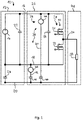
Fig. 1 ein Ausführungsbeispiel eines Stromkreises mit einem AC-Fehler. - Es wird nachfolgend auf
Fig. 1 Bezug genommen, die ein Ausführungsbeispiel eines Stromkreises 10 zeigt. Der Stromkreis 10 umfasst einen Versorger 12, der eine Spannungsquelle 14 umfasst. Die Spannungsquelle 14 ist vorzugsweise eine Gleichspannungsquelle. Der Versorger 12 stellt eine positive Versorgungsschiene 16, eine negative Versorgungsschiene 18 und eine Bezugspotentialschiene 20 bereit. Die Bezugspotentialschiene 20 liegt auf einem Bezugspotential. Das Bezugspotential kann Erde sein. Das Bezugspotential liegt vorzugsweise in der Mitte zwischen den Potentialen der positiven und negativen Versorgungsschiene 16, 18. - Ferner kann der Versorger 12 einen Ausgangskondensator 22 aufweisen. Der Ausgangskondensator 22 ist zwischen die positive Versorgungsschiene 16 und die negative Versorgungsschiene 18 geschaltet.
- Der Versorger 12 kann eine Kapazität 24 zwischen seinen Leitungen und einem auf Bezugspotential liegenden Gehäuse aufweisen. Die Kapazität 24 ist hier als Kondensator modelliert. Die Kapazität 24 kann - aber muss nicht - als Bauelement des Versorgers ausgestaltet sein. Der Versorger 12 ist hier lediglich zur besseren Erläuterung der Funktionsweise dargestellt und kann vielfältige Gestaltungen aufweisen, die als solches bekannt sind.
- Der Stromkreis 10 umfasst einen Stromrichter 26. Der Stromrichter 26 kann als Wechselrichter ausgebildet sein. Der Stromrichter 26 enthält wenigstens einen Phasenzweig 28 mit einer Schalteinrichtung 30. Die Schalteinrichtung 30 umfasst zwei Leistungsschalter, die im Gegentakt betrieben werden können: einen ersten Leistungsschalter 31 und einen zweiten Leistungsschalter 32. Die Schalteinrichtung 30 umfasst ferner eine Ausgangsschiene 34. Die Ausgangsschiene 34 ist zwischen den beiden Leistungsschaltern 32 angeordnet.
- Der Stromrichter 26 enthält ferner einen Zwischenkreiskondensator 36, der zwischen die positiven Versorgungsschiene 16 und die negative Versorgungsschiene 18 geschaltet und vorzugsweise in der Nähe bzw. unmittelbar benachbart zu der Schalteinrichtung 30 angeordnet ist.
- Der Stromrichter 26 umfasst zudem einen Strommessschaltkreis 38. Der Strommessschaltkreis 38 ist an die beiden Versorgungsschienen 16, 18 sowie die Bezugspotentialschiene 20 angeschlossen. Der Strommessschaltkreis 38 umfasst eine Strommesseinrichtung 39, die ausgebildet ist, einen Strom zu messen.
- Die Strommesseinrichtung 39 umfasst eine erste Strommessanordnung 40 und eine zweite Strommessanordnung 42. Die erste Strommessanordnung 40 ist an die positive Versorgungsschiene 16 und an die Bezugspotentialschiene 20 angeschlossen. Die zweite Strommesseinrichtung 42 ist an die negative Versorgungsschiene 18 und an die Bezugspotentialschiene 20 angeschlossen.
- Jede Strommessanordnung 40, 42 enthält einen Stromsensor 44 und einen dazu in Serie geschalteten Messkondensator 46. Der Stromsensor 44 ist an die jeweilige Versorgungsschiene 16, 18 angeschlossen, während der Messkondensator 46 an die Bezugspotentialschiene 20 angeschlossen ist.
- Die Messkondensatoren 46 jeder Strommessanordnung 40, 42 sind als Y-Kondensatoren zwischen den Versorgungsschienen 16, 18 und der Bezugspotentialschiene 20 geschaltet. Die Messkondensatoren 46 können je nach Fall auch Teil eines Entstörkondensatorsatzes sein.
- Der Stromsensor 44 kann einen Shunt-Widerstand für die Strommessung enthalten. Der Shunt-Widerstand ist in Serie zu dem Messkondensator 46 geschaltet. Der Stromsensor 44 kann zusätzlich einen an den Shunt-Widerstand angeschlossenen Komparator für die Messung eines Überstroms in der jeweiligen Strommessanordnung 40, 42 enthalten. Optional kann der Stromsensor 44 einen A/D-Wandler für die exakte Quantifizierung des Überstroms enthalten.
- Es wird nachfolgend davon ausgegangen, dass der Stromkreis 10 einen AC-Isolationsfehler 48 aufweist, der einen unerwünschten Stromfluss erlaubt und hier durch einen Widerstand 50 modelliert ist. Es können jedoch auch andere Arten von AC-Isolationsfehlern 48 detektiert werden. Der AC-Isolationsfehler 48 kann beispielsweise in einen Zuleitungssystem an eines oder mehrere Endgeräte oder in den Endgeräten selbst auftreten. Die Detektion eines Fehlerstroms erfolgt folgendermaßen:
Wenn der Leistungsschalter 31 eingeschaltet ist, wird der positive Pol der Spannungsquelle 14 durch den AC-Isolationsfehler 48 nach Bezugspotential, beispielsweise Masse, gedrückt. Wenn der Leistungsschalter 32 eingeschaltet ist, wird der negative Pol der Spannungsquelle 14 durch den AC-Isolationsfehler 50 nach Bezugspotential, hier Masse, gedrückt. - Diese Änderung der Versorgungsspannung in Bezug auf das Bezugspotential verursacht einen Ladungsträgerfluss durch jeden Messkondensator 46. Dieser Messstrom wird dann zur Ermittlung von des AC-Isolationsfehlers 48 verwendet.
- Mit den hierin beschriebenen Maßnahmen können im Unterschied zu den bekannten Vorrichtungen und Verfahren zusätzlich AC-Isolationsfehler erkannt werden, die lediglich zu geringen Fehlstromwerten führen. Somit ist eine Frühzeiterkennung möglich. Zudem kann durch die direkte Messung des Stroms der Messkondensatoren der Messstrom vom eigentlichen Laststrom entkoppelt werden, sodass einfacher, schneller und genauer gemessen werden kann.
- Um eine Frühzeiterkennung von AC-Isolationsfehlern (48) zu ermöglichen bzw. eine einfachere, schnellere und genauere Messung kleiner Ströme bei Wechselrichtern (26) zu erlauben, wird ein Strommessschaltkreis (38) für einen Stromrichter (26) vorgeschlagen. Der Strommessschaltkreis (38) hat eine positive Versorgungsschiene (16), eine negative Versorgungsschiene (18), eine Bezugspotentialschiene (20) und eine Strommesseinrichtung (39) die einen Y-Kondensator (46) und einen in Serie dazu geschalteten Stromsensor (44) enthält. Durch den wenigstens einen Y-Kondensator (46) kann der Laststrom vom Messstrom entkoppelt werden, sodass mit dem Stromsensor (44) bereits kleine Fehlströme auch bei hohen Lastströmen zuverlässig erfasst werden können.
-
- 10
- Stromkreis
- 12
- Versorger
- 14
- Spannungsquelle
- 16
- positive Versorgungsschiene
- 18
- negative Versorgungsschiene
- 20
- Bezugspotentialschiene
- 22
- Ausgangskondensator
- 24
- Kapazität
- 26
- Stromrichter
- 28
- Phasenzweig
- 30
- Schalteinrichtung
- 31
- erster Leistungsschalter
- 32
- zweiter Leistungsschalter
- 34
- Ausgangsschiene
- 36
- Zwischenkreiskondensator
- 38
- Strommessschaltkreis
- 39
- Strommesseinrichtung
- 40
- erste Strommessanordnung
- 42
- zweite Strommessanordnung
- 44
- Stromsensor
- 46
- Messkondensator
- 48
- AC-Isolationsfehler
- 50
- Widerstand
Claims (14)
- Strommessschaltkreis (38) für einen Stromrichter (26), wobei der Strommessschaltkreis (38) eine positive Versorgungsschiene (16), eine negative Versorgungsschiene (18), eine Bezugspotentialschiene (20) und eine Strommesseinrichtung (39) umfasst, wobei die Strommesseinrichtung (39) an jede Versorgungsschiene (16, 18) und an die Bezugspotentialschiene (20) angeschlossen ist, dadurch gekennzeichnet, dass die Strommesseinrichtung (39) ausgebildet ist, jeweils einen elektrischen Fehlerstrom zwischen einer der Versorgungsschienen (16, 18) und der Bezugspotentialschiene (20) zu messen.
- Strommessschaltkreis (38) nach Anspruch 1, dadurch gekennzeichnet, dass die Strommesseinrichtung (39) wenigstens eine Strommessanordnung (40, 42) enthält, die entweder an die positive oder an die negative Versorgungsschiene (16, 18) sowie an die Bezugspotentialschiene (20) angeschlossen ist, wobei die Strommessanordnung (40, 42) einen Stromsensor (44) und einen in Serie dazu geschalteten Messkondensator (46) enthält.
- Strommessschaltkreis (38) nach Anspruch 2, dadurch gekennzeichnet, dass der Stromsensor (44) an eine der Versorgungsschienen (16, 18) sowie an den Messkondensator (46) angeschlossen ist, wobei der Messkondensator (46) an den Stromsensor (44) und an die Bezugspotentialschiene (20) angeschlossen ist.
- Strommessschaltkreis (38) nach Anspruch 2 oder 3, dadurch gekennzeichnet, dass die Strommesseinrichtung (39) einen Komparator enthält, der ausgebildet und angeschlossen ist, einen Überstrom durch die Strommessanordnung (40, 42) zu erkennen.
- Strommessschaltkreis (38) nach einem der Ansprüche 2 bis 4, dadurch gekennzeichnet, dass die Strommesseinrichtung (39) einen Schaltkreis zur Messung des Stromwertes enthält, der angeschlossen ist, um einen durch die Strommessanordnung (40, 42) fließenden analogen Fehlerstrom in ein digitales Fehlerstromsignal umzuwandeln, das indikativ für das Ausmaß des Fehlerstroms ist.
- Strommessschaltkreis (38) nach einem der vorhergehenden Ansprüche, gekennzeichnet durch einen Zwischenkreiskondensator (36) der an zwischen die positive und die negative Versorgungsschiene (16, 18) geschaltet ist.
- Stromrichterschaltkreis für einen Stromrichter (26), wobei der Stromrichterschaltkreis einen Strommessschaltkreis (38) nach einem der vorhergehenden Ansprüche und wenigstens eine Schalteinrichtung (30) aufweist, wobei die Schalteinrichtung (30) zwischen die Versorgungsschienen (16, 18) geschaltet ist und eine Ausgangsschiene (34) hat.
- Stromrichterschaltkreis nach Anspruch 7, dadurch gekennzeichnet, dass der Zwischenkreiskondensator (36) näher an der Schalteinrichtung (30) angeordnet ist als jede Strommessanordnung (40, 42).
- Stromrichterschaltkreis nach einem der Ansprüche 7 oder 8, dadurch gekennzeichnet, dass der Stromrichter (26) als Wechselrichter konfiguriert ist.
- Strommessvorrichtung für einen Stromrichter (26), dadurch gekennzeichnet, dass die Strommessvorrichtung einen Strommessschaltkreis (38) nach einem der Ansprüche 1 bis 6 aufweist.
- Stromrichter (26) umfassend einen Strommessschaltkreis (38) nach einem der Ansprüche 1 bis 6 und/oder einen Stromrichterschaltkreis nach einem der Ansprüche 7 oder 8 und/oder eine Strommessvorrichtung nach Anspruch 9.
- Stromrichter (26) nach Anspruch 11, dadurch gekennzeichnet, dass der Stromrichter (26) als Wechselrichter konfiguriert ist.
- Strommessverfahren zum Feststellen eines aufgrund eines AC-Isolationsfehlers (48) in einem an einen Stromrichter (26) angeschlossenen Stromkreis (10) erzeugten Fehlerstromes, indem ein durch einen zwischen einer Versorgungsschiene (16, 18) des Stromrichters (26) und eine Bezugspotentialschiene (20) des Stromrichters (26) geschalteten Messkondensator (46) fließender Strom gemessen wird, wobei ein AC-Isolationsfehler (48) angenommen wird, wenn bei einem Schaltvorgang ein Stromfluss durch den Messkondensator (46) gemessen wird, der einen vorgegebenen Schwellwert überschreitet.
- Strommessverfahren nach Anspruch 13, dadurch gekennzeichnet, dass der Stromrichter (26) als Wechselrichter konfiguriert ist, wobei der durch den Messkondensator (46) fließende Strom während der positiven Halbwelle und/oder während der negativen Halbwelle gemessen wird, wobei ein AC-Isolationsfehler (48) angenommen wird, wenn bei einem der Schaltvorgänge ein Stromfluss durch den Messkondensator (46) gemessen wird, der einen vorgegebenen Schwellwert überschreitet.
Priority Applications (3)
| Application Number | Priority Date | Filing Date | Title |
|---|---|---|---|
| EP21175096.3A EP4092431B1 (de) | 2021-05-20 | 2021-05-20 | Stromrichterschaltkreis und stromrichter |
| US17/747,180 US12132384B2 (en) | 2021-05-20 | 2022-05-18 | Current measuring circuit for a converter, converter circuit and converter |
| CN202210545212.2A CN115372684A (zh) | 2021-05-20 | 2022-05-19 | 用于转换器的电流测量电路、转换器电路和转换器 |
Applications Claiming Priority (1)
| Application Number | Priority Date | Filing Date | Title |
|---|---|---|---|
| EP21175096.3A EP4092431B1 (de) | 2021-05-20 | 2021-05-20 | Stromrichterschaltkreis und stromrichter |
Publications (2)
| Publication Number | Publication Date |
|---|---|
| EP4092431A1 true EP4092431A1 (de) | 2022-11-23 |
| EP4092431B1 EP4092431B1 (de) | 2025-01-08 |
Family
ID=76034581
Family Applications (1)
| Application Number | Title | Priority Date | Filing Date |
|---|---|---|---|
| EP21175096.3A Active EP4092431B1 (de) | 2021-05-20 | 2021-05-20 | Stromrichterschaltkreis und stromrichter |
Country Status (3)
| Country | Link |
|---|---|
| US (1) | US12132384B2 (de) |
| EP (1) | EP4092431B1 (de) |
| CN (1) | CN115372684A (de) |
Families Citing this family (3)
| Publication number | Priority date | Publication date | Assignee | Title |
|---|---|---|---|---|
| JP2024175949A (ja) * | 2023-06-07 | 2024-12-19 | 株式会社 東京ウエルズ | 検査装置及び検査方法 |
| EP4478061A1 (de) * | 2023-06-14 | 2024-12-18 | Hamilton Sundstrand Corporation | Isolationsfehlerüberwachung |
| DE102024110826A1 (de) * | 2024-04-17 | 2025-10-23 | Bucher Hydraulics Ag | Schaltung zur Isolationsüberwachung und elektrisches System |
Citations (8)
| Publication number | Priority date | Publication date | Assignee | Title |
|---|---|---|---|---|
| US20010048310A1 (en) * | 2000-05-30 | 2001-12-06 | International Rectifier Corporation | Motor insulation fault detection by sensing ground leak current |
| CN1332211C (zh) * | 2004-06-07 | 2007-08-15 | 山东大学 | 直流电源系统接地故障检测方法及其检测电路 |
| US8618753B2 (en) | 2009-06-11 | 2013-12-31 | Kabushiki Kaisha Toyota Jidoshokki | Inverter device |
| US8947838B2 (en) | 2010-08-31 | 2015-02-03 | Hitachi Automotive Systems, Ltd. | Overcurrent fault detection device for electrical drive control system |
| DE112014002853T5 (de) * | 2013-11-22 | 2016-03-03 | Mitsubishi Electric Corporation | Isolationsdetektor und elektrische Vorrichtung |
| EP3165491A1 (de) * | 2012-11-05 | 2017-05-10 | KONE Corporation | Aufzugssystem und verfahren zur überwachung der elektrischen sicherheit in einem aufzugssystem |
| JP6398704B2 (ja) | 2014-12-25 | 2018-10-03 | アイシン・エィ・ダブリュ株式会社 | インバータ装置 |
| EP3631927A1 (de) * | 2017-06-29 | 2020-04-08 | Huawei Technologies Co., Ltd. | Fernstromeinheit, gleichstromversorgungssystem und gleichstromversorgungssystemfehlerdetektionsverfahren |
Family Cites Families (7)
| Publication number | Priority date | Publication date | Assignee | Title |
|---|---|---|---|---|
| JP2008157672A (ja) * | 2006-12-21 | 2008-07-10 | Fanuc Ltd | モータの絶縁劣化検出装置 |
| ATE547713T1 (de) * | 2008-09-23 | 2012-03-15 | Abb Oy | Strommessung in einem wechselrichter und in einem frequenzwandler |
| US20140167779A1 (en) * | 2012-12-18 | 2014-06-19 | Caterpillar Inc. | Ground Fault Detection System for a Power Supply System |
| JP6017481B2 (ja) * | 2014-03-05 | 2016-11-02 | ファナック株式会社 | 絶縁抵抗検出機能を備えたモータ駆動装置及びモータの絶縁抵抗検出方法 |
| US9758044B2 (en) * | 2014-10-02 | 2017-09-12 | Ford Global Technologies, Llc | Bus leakage resistance estimation for electrical isolation testing and diagnostics |
| DE102018121979A1 (de) * | 2018-09-10 | 2020-03-12 | Bender Gmbh & Co. Kg | Verfahren zur Isolationsüberwachung eines Umrichter-gespeisten Stromversorgungssystems |
| JP7184706B2 (ja) * | 2019-05-10 | 2022-12-06 | 株式会社日立産機システム | 電力変換装置、それを用いたシステム、およびその診断方法 |
-
2021
- 2021-05-20 EP EP21175096.3A patent/EP4092431B1/de active Active
-
2022
- 2022-05-18 US US17/747,180 patent/US12132384B2/en active Active
- 2022-05-19 CN CN202210545212.2A patent/CN115372684A/zh active Pending
Patent Citations (8)
| Publication number | Priority date | Publication date | Assignee | Title |
|---|---|---|---|---|
| US20010048310A1 (en) * | 2000-05-30 | 2001-12-06 | International Rectifier Corporation | Motor insulation fault detection by sensing ground leak current |
| CN1332211C (zh) * | 2004-06-07 | 2007-08-15 | 山东大学 | 直流电源系统接地故障检测方法及其检测电路 |
| US8618753B2 (en) | 2009-06-11 | 2013-12-31 | Kabushiki Kaisha Toyota Jidoshokki | Inverter device |
| US8947838B2 (en) | 2010-08-31 | 2015-02-03 | Hitachi Automotive Systems, Ltd. | Overcurrent fault detection device for electrical drive control system |
| EP3165491A1 (de) * | 2012-11-05 | 2017-05-10 | KONE Corporation | Aufzugssystem und verfahren zur überwachung der elektrischen sicherheit in einem aufzugssystem |
| DE112014002853T5 (de) * | 2013-11-22 | 2016-03-03 | Mitsubishi Electric Corporation | Isolationsdetektor und elektrische Vorrichtung |
| JP6398704B2 (ja) | 2014-12-25 | 2018-10-03 | アイシン・エィ・ダブリュ株式会社 | インバータ装置 |
| EP3631927A1 (de) * | 2017-06-29 | 2020-04-08 | Huawei Technologies Co., Ltd. | Fernstromeinheit, gleichstromversorgungssystem und gleichstromversorgungssystemfehlerdetektionsverfahren |
Also Published As
| Publication number | Publication date |
|---|---|
| EP4092431B1 (de) | 2025-01-08 |
| US12132384B2 (en) | 2024-10-29 |
| US20220376601A1 (en) | 2022-11-24 |
| CN115372684A (zh) | 2022-11-22 |
Similar Documents
| Publication | Publication Date | Title |
|---|---|---|
| DE102006022686B4 (de) | Messanordnung zur Ermittlung des Isolationswiderstandes einer elektrischen Vorrichtung oder einer Anlage | |
| DE102011014561B4 (de) | Verfahren und Vorrichtung zum Überwachen einer Elektromotor-Steuerschaltung | |
| AT511807B1 (de) | Verfahren und vorrichtung zur online-erkennung einer zustandsverschlechterung einer isolierung in einer elektrischen maschine | |
| EP4092431B1 (de) | Stromrichterschaltkreis und stromrichter | |
| WO2011157468A1 (de) | Verfahren und vorrichtung zur überwachung des isolationswiderstandes in einem ungeerdeten elektrischen netz | |
| EP3524985A1 (de) | Vorrichtung und verfahren für eine isolationsüberwachung mit erkennung eines fehlerbehafteten aussenleiters in einem 3-phasigen ungeerdeten stromversorgungssystem | |
| EP3631976B1 (de) | Verfahren zur erkennung eines kontaktfehlers in einer photovoltaikanlage | |
| WO2020043386A1 (de) | Akkupack sowie ladeverfahren für ein akkupack | |
| DE102008018244B3 (de) | Vorrichtung und Verfahren zum Erkennen eines Fehlers in einer Leistungsbrückenschaltung | |
| DE102012019095B4 (de) | Einrichtung zur Überwachung eines Isolationswiderstandes von Netzen | |
| EP3403107A1 (de) | Verfahren und vorrichtung zur kurzschlussueberwachung einer drehstromlast | |
| WO2013102505A1 (de) | Verfahren und vorrichtung zur überwachung eines umrichters | |
| EP3723220B1 (de) | Orten eines erdschlusses in einem gleichstromnetz | |
| DE102023201657A1 (de) | Vorrichtung und Verfahren zur Überwachung von Halbleiterschaltelementen, Leistungsmodul und elektrischer Stromrichter | |
| DE102014103321A1 (de) | Isolationsüberwachung für reihenkompensierte Wicklungen eines kontaktlosen Energieübertragungssystems | |
| DE4418124C2 (de) | Vorrichtung zum Erkennen einer Isolationsverschlechterung an Stromversorgungsleitungen | |
| EP3517901A1 (de) | Magnetisch-induktives durchflussmessgerät | |
| WO2022179984A1 (de) | Verfahren und vorrichtung zum erfassen eines isolationswiderstands einer an einen geteilten zwischenkreis angeschlossenen gleichspannungsquelle im netzparallelbetrieb | |
| DE102016212211B4 (de) | Kurzschlusserkennung | |
| DE102017206169A1 (de) | Stromrichtereinrichtung für eine elektrische Maschine, Kraftfahrzeug und Verfahren zum Betreiben einer Stromrichtereinrichtung | |
| WO2012045103A1 (de) | Detektoreinheit zum erkennen einer neutralleiterunterbrechung in einem symmetrischen mehrphasenstromnetz | |
| BE1027538B1 (de) | Verfahren zur Verifizierung von Phasenzuordnungen | |
| DE102008049781A1 (de) | Verfahren und Messvorrichtung zur Messung des Ausgangsstroms einer getakteten Halbbrückenschaltung | |
| DE102013002018A1 (de) | Schaltungsanordnung und Verfahren zur Isolationsüberwachung einer Schaltungsanordnung | |
| DE102023109195B3 (de) | Verfahren zur Plausibilisierung gemessener elektrischer Messgrößen einer Antriebseinheit |
Legal Events
| Date | Code | Title | Description |
|---|---|---|---|
| PUAI | Public reference made under article 153(3) epc to a published international application that has entered the european phase |
Free format text: ORIGINAL CODE: 0009012 |
|
| STAA | Information on the status of an ep patent application or granted ep patent |
Free format text: STATUS: THE APPLICATION HAS BEEN PUBLISHED |
|
| AK | Designated contracting states |
Kind code of ref document: A1 Designated state(s): AL AT BE BG CH CY CZ DE DK EE ES FI FR GB GR HR HU IE IS IT LI LT LU LV MC MK MT NL NO PL PT RO RS SE SI SK SM TR |
|
| STAA | Information on the status of an ep patent application or granted ep patent |
Free format text: STATUS: REQUEST FOR EXAMINATION WAS MADE |
|
| 17P | Request for examination filed |
Effective date: 20230523 |
|
| RBV | Designated contracting states (corrected) |
Designated state(s): AL AT BE BG CH CY CZ DE DK EE ES FI FR GB GR HR HU IE IS IT LI LT LU LV MC MK MT NL NO PL PT RO RS SE SI SK SM TR |
|
| GRAP | Despatch of communication of intention to grant a patent |
Free format text: ORIGINAL CODE: EPIDOSNIGR1 |
|
| STAA | Information on the status of an ep patent application or granted ep patent |
Free format text: STATUS: GRANT OF PATENT IS INTENDED |
|
| INTG | Intention to grant announced |
Effective date: 20240816 |
|
| GRAS | Grant fee paid |
Free format text: ORIGINAL CODE: EPIDOSNIGR3 |
|
| GRAA | (expected) grant |
Free format text: ORIGINAL CODE: 0009210 |
|
| STAA | Information on the status of an ep patent application or granted ep patent |
Free format text: STATUS: THE PATENT HAS BEEN GRANTED |
|
| AK | Designated contracting states |
Kind code of ref document: B1 Designated state(s): AL AT BE BG CH CY CZ DE DK EE ES FI FR GB GR HR HU IE IS IT LI LT LU LV MC MK MT NL NO PL PT RO RS SE SI SK SM TR |
|
| REG | Reference to a national code |
Ref country code: GB Ref legal event code: FG4D Free format text: NOT ENGLISH |
|
| REG | Reference to a national code |
Ref country code: CH Ref legal event code: EP |
|
| REG | Reference to a national code |
Ref country code: DE Ref legal event code: R096 Ref document number: 502021006333 Country of ref document: DE |
|
| REG | Reference to a national code |
Ref country code: IE Ref legal event code: FG4D Free format text: LANGUAGE OF EP DOCUMENT: GERMAN |
|
| REG | Reference to a national code |
Ref country code: LT Ref legal event code: MG9D |
|
| REG | Reference to a national code |
Ref country code: NL Ref legal event code: MP Effective date: 20250108 |
|
| PG25 | Lapsed in a contracting state [announced via postgrant information from national office to epo] |
Ref country code: NL Free format text: LAPSE BECAUSE OF FAILURE TO SUBMIT A TRANSLATION OF THE DESCRIPTION OR TO PAY THE FEE WITHIN THE PRESCRIBED TIME-LIMIT Effective date: 20250108 |
|
| PG25 | Lapsed in a contracting state [announced via postgrant information from national office to epo] |
Ref country code: RS Free format text: LAPSE BECAUSE OF FAILURE TO SUBMIT A TRANSLATION OF THE DESCRIPTION OR TO PAY THE FEE WITHIN THE PRESCRIBED TIME-LIMIT Effective date: 20250408 |
|
| PG25 | Lapsed in a contracting state [announced via postgrant information from national office to epo] |
Ref country code: FI Free format text: LAPSE BECAUSE OF FAILURE TO SUBMIT A TRANSLATION OF THE DESCRIPTION OR TO PAY THE FEE WITHIN THE PRESCRIBED TIME-LIMIT Effective date: 20250108 |
|
| PG25 | Lapsed in a contracting state [announced via postgrant information from national office to epo] |
Ref country code: PL Free format text: LAPSE BECAUSE OF FAILURE TO SUBMIT A TRANSLATION OF THE DESCRIPTION OR TO PAY THE FEE WITHIN THE PRESCRIBED TIME-LIMIT Effective date: 20250108 |
|
| PGFP | Annual fee paid to national office [announced via postgrant information from national office to epo] |
Ref country code: DE Payment date: 20250521 Year of fee payment: 5 |
|
| PG25 | Lapsed in a contracting state [announced via postgrant information from national office to epo] |
Ref country code: ES Free format text: LAPSE BECAUSE OF FAILURE TO SUBMIT A TRANSLATION OF THE DESCRIPTION OR TO PAY THE FEE WITHIN THE PRESCRIBED TIME-LIMIT Effective date: 20250108 |
|
| PGFP | Annual fee paid to national office [announced via postgrant information from national office to epo] |
Ref country code: GB Payment date: 20250527 Year of fee payment: 5 |
|
| PG25 | Lapsed in a contracting state [announced via postgrant information from national office to epo] |
Ref country code: NO Free format text: LAPSE BECAUSE OF FAILURE TO SUBMIT A TRANSLATION OF THE DESCRIPTION OR TO PAY THE FEE WITHIN THE PRESCRIBED TIME-LIMIT Effective date: 20250408 Ref country code: IS Free format text: LAPSE BECAUSE OF FAILURE TO SUBMIT A TRANSLATION OF THE DESCRIPTION OR TO PAY THE FEE WITHIN THE PRESCRIBED TIME-LIMIT Effective date: 20250508 |
|
| PG25 | Lapsed in a contracting state [announced via postgrant information from national office to epo] |
Ref country code: HR Free format text: LAPSE BECAUSE OF FAILURE TO SUBMIT A TRANSLATION OF THE DESCRIPTION OR TO PAY THE FEE WITHIN THE PRESCRIBED TIME-LIMIT Effective date: 20250108 |
|
| PG25 | Lapsed in a contracting state [announced via postgrant information from national office to epo] |
Ref country code: LV Free format text: LAPSE BECAUSE OF FAILURE TO SUBMIT A TRANSLATION OF THE DESCRIPTION OR TO PAY THE FEE WITHIN THE PRESCRIBED TIME-LIMIT Effective date: 20250108 Ref country code: PT Free format text: LAPSE BECAUSE OF FAILURE TO SUBMIT A TRANSLATION OF THE DESCRIPTION OR TO PAY THE FEE WITHIN THE PRESCRIBED TIME-LIMIT Effective date: 20250508 |
|
| PGFP | Annual fee paid to national office [announced via postgrant information from national office to epo] |
Ref country code: FR Payment date: 20250528 Year of fee payment: 5 |
|
| PG25 | Lapsed in a contracting state [announced via postgrant information from national office to epo] |
Ref country code: GR Free format text: LAPSE BECAUSE OF FAILURE TO SUBMIT A TRANSLATION OF THE DESCRIPTION OR TO PAY THE FEE WITHIN THE PRESCRIBED TIME-LIMIT Effective date: 20250409 Ref country code: BG Free format text: LAPSE BECAUSE OF FAILURE TO SUBMIT A TRANSLATION OF THE DESCRIPTION OR TO PAY THE FEE WITHIN THE PRESCRIBED TIME-LIMIT Effective date: 20250108 |
|
| PGFP | Annual fee paid to national office [announced via postgrant information from national office to epo] |
Ref country code: AT Payment date: 20250721 Year of fee payment: 5 |
|
| PG25 | Lapsed in a contracting state [announced via postgrant information from national office to epo] |
Ref country code: SE Free format text: LAPSE BECAUSE OF FAILURE TO SUBMIT A TRANSLATION OF THE DESCRIPTION OR TO PAY THE FEE WITHIN THE PRESCRIBED TIME-LIMIT Effective date: 20250108 |
|
| PG25 | Lapsed in a contracting state [announced via postgrant information from national office to epo] |
Ref country code: SM Free format text: LAPSE BECAUSE OF FAILURE TO SUBMIT A TRANSLATION OF THE DESCRIPTION OR TO PAY THE FEE WITHIN THE PRESCRIBED TIME-LIMIT Effective date: 20250108 |
|
| REG | Reference to a national code |
Ref country code: DE Ref legal event code: R097 Ref document number: 502021006333 Country of ref document: DE |
|
| PG25 | Lapsed in a contracting state [announced via postgrant information from national office to epo] |
Ref country code: DK Free format text: LAPSE BECAUSE OF FAILURE TO SUBMIT A TRANSLATION OF THE DESCRIPTION OR TO PAY THE FEE WITHIN THE PRESCRIBED TIME-LIMIT Effective date: 20250108 |
|
| PG25 | Lapsed in a contracting state [announced via postgrant information from national office to epo] |
Ref country code: CZ Free format text: LAPSE BECAUSE OF FAILURE TO SUBMIT A TRANSLATION OF THE DESCRIPTION OR TO PAY THE FEE WITHIN THE PRESCRIBED TIME-LIMIT Effective date: 20250108 Ref country code: EE Free format text: LAPSE BECAUSE OF FAILURE TO SUBMIT A TRANSLATION OF THE DESCRIPTION OR TO PAY THE FEE WITHIN THE PRESCRIBED TIME-LIMIT Effective date: 20250108 |
|
| PG25 | Lapsed in a contracting state [announced via postgrant information from national office to epo] |
Ref country code: RO Free format text: LAPSE BECAUSE OF FAILURE TO SUBMIT A TRANSLATION OF THE DESCRIPTION OR TO PAY THE FEE WITHIN THE PRESCRIBED TIME-LIMIT Effective date: 20250108 |
|
| PG25 | Lapsed in a contracting state [announced via postgrant information from national office to epo] |
Ref country code: SK Free format text: LAPSE BECAUSE OF FAILURE TO SUBMIT A TRANSLATION OF THE DESCRIPTION OR TO PAY THE FEE WITHIN THE PRESCRIBED TIME-LIMIT Effective date: 20250108 |
|
| PLBE | No opposition filed within time limit |
Free format text: ORIGINAL CODE: 0009261 |
|
| STAA | Information on the status of an ep patent application or granted ep patent |
Free format text: STATUS: NO OPPOSITION FILED WITHIN TIME LIMIT |
|
| REG | Reference to a national code |
Ref country code: CH Ref legal event code: L10 Free format text: ST27 STATUS EVENT CODE: U-0-0-L10-L00 (AS PROVIDED BY THE NATIONAL OFFICE) Effective date: 20251119 |
|
| 26N | No opposition filed |
Effective date: 20251009 |
|
| REG | Reference to a national code |
Ref country code: CH Ref legal event code: H13 Free format text: ST27 STATUS EVENT CODE: U-0-0-H10-H13 (AS PROVIDED BY THE NATIONAL OFFICE) Effective date: 20251223 |
|
| PG25 | Lapsed in a contracting state [announced via postgrant information from national office to epo] |
Ref country code: LU Free format text: LAPSE BECAUSE OF NON-PAYMENT OF DUE FEES Effective date: 20250520 |
|
| PG25 | Lapsed in a contracting state [announced via postgrant information from national office to epo] |
Ref country code: CH Free format text: LAPSE BECAUSE OF NON-PAYMENT OF DUE FEES Effective date: 20250531 |
|
| PG25 | Lapsed in a contracting state [announced via postgrant information from national office to epo] |
Ref country code: IT Free format text: LAPSE BECAUSE OF FAILURE TO SUBMIT A TRANSLATION OF THE DESCRIPTION OR TO PAY THE FEE WITHIN THE PRESCRIBED TIME-LIMIT Effective date: 20250108 |
|
| REG | Reference to a national code |
Ref country code: BE Ref legal event code: MM Effective date: 20250531 |
|
| PG25 | Lapsed in a contracting state [announced via postgrant information from national office to epo] |
Ref country code: MC Free format text: LAPSE BECAUSE OF FAILURE TO SUBMIT A TRANSLATION OF THE DESCRIPTION OR TO PAY THE FEE WITHIN THE PRESCRIBED TIME-LIMIT Effective date: 20250108 |
|
| PG25 | Lapsed in a contracting state [announced via postgrant information from national office to epo] |
Ref country code: IE Free format text: LAPSE BECAUSE OF NON-PAYMENT OF DUE FEES Effective date: 20250520 |
|
| PG25 | Lapsed in a contracting state [announced via postgrant information from national office to epo] |
Ref country code: BE Free format text: LAPSE BECAUSE OF NON-PAYMENT OF DUE FEES Effective date: 20250531 |