EP4092361A1 - Air conditioning device for vehicle - Google Patents
Air conditioning device for vehicle Download PDFInfo
- Publication number
- EP4092361A1 EP4092361A1 EP20913831.2A EP20913831A EP4092361A1 EP 4092361 A1 EP4092361 A1 EP 4092361A1 EP 20913831 A EP20913831 A EP 20913831A EP 4092361 A1 EP4092361 A1 EP 4092361A1
- Authority
- EP
- European Patent Office
- Prior art keywords
- airflow
- indoor
- gas sensor
- carbon dioxide
- refrigerant
- Prior art date
- Legal status (The legal status is an assumption and is not a legal conclusion. Google has not performed a legal analysis and makes no representation as to the accuracy of the status listed.)
- Granted
Links
Images






Classifications
-
- B—PERFORMING OPERATIONS; TRANSPORTING
- B60—VEHICLES IN GENERAL
- B60H—ARRANGEMENTS OF HEATING, COOLING, VENTILATING OR OTHER AIR-TREATING DEVICES SPECIALLY ADAPTED FOR PASSENGER OR GOODS SPACES OF VEHICLES
- B60H1/00—Heating, cooling or ventilating devices
- B60H1/00007—Combined heating, ventilating, or cooling devices
- B60H1/00021—Air flow details of HVAC devices
-
- B—PERFORMING OPERATIONS; TRANSPORTING
- B60—VEHICLES IN GENERAL
- B60H—ARRANGEMENTS OF HEATING, COOLING, VENTILATING OR OTHER AIR-TREATING DEVICES SPECIALLY ADAPTED FOR PASSENGER OR GOODS SPACES OF VEHICLES
- B60H1/00—Heating, cooling or ventilating devices
- B60H1/00642—Control systems or circuits; Control members or indication devices for heating, cooling or ventilating devices
- B60H1/00735—Control systems or circuits characterised by their input, i.e. by the detection, measurement or calculation of particular conditions, e.g. signal treatment, dynamic models
- B60H1/00792—Arrangement of detectors
-
- B—PERFORMING OPERATIONS; TRANSPORTING
- B60—VEHICLES IN GENERAL
- B60H—ARRANGEMENTS OF HEATING, COOLING, VENTILATING OR OTHER AIR-TREATING DEVICES SPECIALLY ADAPTED FOR PASSENGER OR GOODS SPACES OF VEHICLES
- B60H1/00—Heating, cooling or ventilating devices
- B60H1/00642—Control systems or circuits; Control members or indication devices for heating, cooling or ventilating devices
- B60H1/00814—Control systems or circuits characterised by their output, for controlling particular components of the heating, cooling or ventilating installation
- B60H1/00821—Control systems or circuits characterised by their output, for controlling particular components of the heating, cooling or ventilating installation the components being ventilating, air admitting or air distributing devices
- B60H1/00835—Damper doors, e.g. position control
- B60H1/00849—Damper doors, e.g. position control for selectively commanding the induction of outside or inside air
-
- B—PERFORMING OPERATIONS; TRANSPORTING
- B60—VEHICLES IN GENERAL
- B60H—ARRANGEMENTS OF HEATING, COOLING, VENTILATING OR OTHER AIR-TREATING DEVICES SPECIALLY ADAPTED FOR PASSENGER OR GOODS SPACES OF VEHICLES
- B60H1/00—Heating, cooling or ventilating devices
- B60H1/00642—Control systems or circuits; Control members or indication devices for heating, cooling or ventilating devices
- B60H1/00978—Control systems or circuits characterised by failure of detection or safety means; Diagnostic methods
-
- B—PERFORMING OPERATIONS; TRANSPORTING
- B61—RAILWAYS
- B61D—BODY DETAILS OR KINDS OF RAILWAY VEHICLES
- B61D27/00—Heating, cooling, ventilating, or air-conditioning
- B61D27/0018—Air-conditioning means, i.e. combining at least two of the following ways of treating or supplying air, namely heating, cooling or ventilating
-
- F—MECHANICAL ENGINEERING; LIGHTING; HEATING; WEAPONS; BLASTING
- F25—REFRIGERATION OR COOLING; COMBINED HEATING AND REFRIGERATION SYSTEMS; HEAT PUMP SYSTEMS; MANUFACTURE OR STORAGE OF ICE; LIQUEFACTION SOLIDIFICATION OF GASES
- F25B—REFRIGERATION MACHINES, PLANTS OR SYSTEMS; COMBINED HEATING AND REFRIGERATION SYSTEMS; HEAT PUMP SYSTEMS
- F25B49/00—Arrangement or mounting of control or safety devices
- F25B49/005—Arrangement or mounting of control or safety devices of safety devices
-
- B—PERFORMING OPERATIONS; TRANSPORTING
- B60—VEHICLES IN GENERAL
- B60H—ARRANGEMENTS OF HEATING, COOLING, VENTILATING OR OTHER AIR-TREATING DEVICES SPECIALLY ADAPTED FOR PASSENGER OR GOODS SPACES OF VEHICLES
- B60H1/00—Heating, cooling or ventilating devices
- B60H1/00007—Combined heating, ventilating, or cooling devices
- B60H1/00021—Air flow details of HVAC devices
- B60H2001/00078—Assembling, manufacturing or layout details
- B60H2001/00092—Assembling, manufacturing or layout details of air deflecting or air directing means inside the device
-
- F—MECHANICAL ENGINEERING; LIGHTING; HEATING; WEAPONS; BLASTING
- F25—REFRIGERATION OR COOLING; COMBINED HEATING AND REFRIGERATION SYSTEMS; HEAT PUMP SYSTEMS; MANUFACTURE OR STORAGE OF ICE; LIQUEFACTION SOLIDIFICATION OF GASES
- F25B—REFRIGERATION MACHINES, PLANTS OR SYSTEMS; COMBINED HEATING AND REFRIGERATION SYSTEMS; HEAT PUMP SYSTEMS
- F25B2309/00—Gas cycle refrigeration machines
- F25B2309/06—Compression machines, plants or systems characterised by the refrigerant being carbon dioxide
-
- F—MECHANICAL ENGINEERING; LIGHTING; HEATING; WEAPONS; BLASTING
- F25—REFRIGERATION OR COOLING; COMBINED HEATING AND REFRIGERATION SYSTEMS; HEAT PUMP SYSTEMS; MANUFACTURE OR STORAGE OF ICE; LIQUEFACTION SOLIDIFICATION OF GASES
- F25B—REFRIGERATION MACHINES, PLANTS OR SYSTEMS; COMBINED HEATING AND REFRIGERATION SYSTEMS; HEAT PUMP SYSTEMS
- F25B2313/00—Compression machines, plants or systems with reversible cycle not otherwise provided for
- F25B2313/029—Control issues
- F25B2313/0293—Control issues related to the indoor fan, e.g. controlling speed
-
- F—MECHANICAL ENGINEERING; LIGHTING; HEATING; WEAPONS; BLASTING
- F25—REFRIGERATION OR COOLING; COMBINED HEATING AND REFRIGERATION SYSTEMS; HEAT PUMP SYSTEMS; MANUFACTURE OR STORAGE OF ICE; LIQUEFACTION SOLIDIFICATION OF GASES
- F25B—REFRIGERATION MACHINES, PLANTS OR SYSTEMS; COMBINED HEATING AND REFRIGERATION SYSTEMS; HEAT PUMP SYSTEMS
- F25B2500/00—Problems to be solved
- F25B2500/22—Preventing, detecting or repairing leaks of refrigeration fluids
- F25B2500/222—Detecting refrigerant leaks
-
- F—MECHANICAL ENGINEERING; LIGHTING; HEATING; WEAPONS; BLASTING
- F25—REFRIGERATION OR COOLING; COMBINED HEATING AND REFRIGERATION SYSTEMS; HEAT PUMP SYSTEMS; MANUFACTURE OR STORAGE OF ICE; LIQUEFACTION SOLIDIFICATION OF GASES
- F25B—REFRIGERATION MACHINES, PLANTS OR SYSTEMS; COMBINED HEATING AND REFRIGERATION SYSTEMS; HEAT PUMP SYSTEMS
- F25B2600/00—Control issues
- F25B2600/02—Compressor control
- F25B2600/025—Compressor control by controlling speed
- F25B2600/0251—Compressor control by controlling speed with on-off operation
-
- F—MECHANICAL ENGINEERING; LIGHTING; HEATING; WEAPONS; BLASTING
- F25—REFRIGERATION OR COOLING; COMBINED HEATING AND REFRIGERATION SYSTEMS; HEAT PUMP SYSTEMS; MANUFACTURE OR STORAGE OF ICE; LIQUEFACTION SOLIDIFICATION OF GASES
- F25B—REFRIGERATION MACHINES, PLANTS OR SYSTEMS; COMBINED HEATING AND REFRIGERATION SYSTEMS; HEAT PUMP SYSTEMS
- F25B2600/00—Control issues
- F25B2600/11—Fan speed control
Definitions
- the present disclosure relates to an air conditioning apparatus for a vehicle.
- an air conditioning apparatus for a vehicle that performs air conditioning of a vehicular compartment by a refrigeration cycle device that employs carbon dioxide as a refrigerant.
- the refrigeration cycle device includes an indoor heat exchanger that performs heat exchange between the refrigerant and air of the vehicular compartment.
- the air conditioning apparatus for a vehicle includes (i) an indoor fan that forms airflow passing through the indoor heat exchanger, (ii) a gas sensor that detects a concentration of carbon dioxide gas at a position located downstream of the indoor heat exchanger with respect to a direction in which the airflow flows, and (iii) a control device that determines, by using a result of the detection by the gas sensor, whether leakage of the refrigerant from the indoor exchanger is occurring.
- Patent Literature 1 International Publication No. WO 00/59748
- the airflow after passage through the indoor heat exchanger directly hits the gas sensor. This is a factor that leads to a decrease in accuracy of the detection by the gas sensor.
- An objective of the present disclosure is to provide an air conditioning apparatus, for a vehicle, that enables high-accuracy detection of the concentration of carbon dioxide gas due to leakage of refrigerant.
- an air conditioning apparatus for a vehicle includes (i) a casing defining an indoor chamber communicating with a vehicular compartment of the vehicle, (ii) an indoor heat exchanger arranged in the indoor chamber and having an interior for flow therethrough of a refrigerant containing carbon dioxide, (iii) a cooperation device included in, together with the indoor heat exchanger, a refrigeration cycle device for circulation therethrough of the refrigerant, (iv) an indoor fan that is arranged in the indoor chamber and forms airflow by air flowing from the vehicular compartment into the indoor chamber, passing through the indoor heat exchanger, and flowing out to return to the vehicular compartment, and (v) a first gas sensor that detects a concentration of carbon dioxide gas in a path of the airflow at a position located downstream of the indoor heat exchanger.
- the first gas sensor includes (i) a sensing portion that reacts in accordance with the concentration of the carbon dioxide gas and (ii) a windbreak plate that prevents the airflow from hitting the sensing
- the windbreak plate can prevent the airflow from hitting the sensing portion, allowing the first gas sensor to accurately detect the concentration of the carbon dioxide gas due to leakage of the refrigerant.
- Embodiments 1-7 air conditioning apparatuses for a railroad vehicle according to Embodiments 1-7, in which the vehicle is a railroad vehicle, are described with reference to the drawings.
- components that are the same or equivalent are assigned the same reference sign.
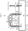
- FIG. 1 is a schematic diagram illustrating a part of configuration of an air conditioning apparatus 800 for a railroad vehicle according to the present embodiment.
- the air conditioning apparatus 800 for the railroad vehicle performs air conditioning of a passenger compartment 910 that is a vehicular compartment defined in a railroad vehicle 900 for human occupancy.
- the air conditioning apparatus 800 for the railroad vehicle includes an indoor heat exchanger 130 having an interior for flow therethrough of a refrigerant containing carbon dioxide that is hereinafter referred to as the "carbon dioxide refrigerant".
- the indoor heat exchanger 130 is a part of a refrigeration cycle device 100 that provides a refrigeration cycle by using the carbon dioxide refrigerant.
- a refrigerant that contains carbon dioxide as main component more specifically, a refrigerant corresponding to the refrigerant number "R-744" and having 99.9 % or more carbon dioxide purity, is preferable as the carbon dioxide refrigerant, from the viewpoint of non-combustibility and a low global warming potential.
- the air conditioning apparatus 800 for the railroad vehicle includes a casing 700 that defines an indoor chamber 710 that is a space in which the indoor heat exchanger 130 is arranged.
- the indoor chamber 710 communicates with the passenger compartment 910.
- the air conditioning apparatus 800 for the railroad vehicle includes an indoor fan 310 arranged in the indoor chamber 710.
- the indoor fan 310 forms airflow AC by air flowing from the passenger compartment 910 into the indoor chamber 710, passing through the indoor heat exchanger 130, and flowing out to return to the passenger compartment 910.
- air that is included in the airflow AC and flows from the passenger compartment 910 into the indoor chamber 710 to the indoor heat exchanger 130 is called the return air RA.
- air that flows out from the indoor chamber 710 to the passenger compartment 910 after passage through the indoor heat exchanger 130 is called the supply air SA.
- the return air RA passes through a return duct 920 that is a duct communicating with the passenger compartment 910, and flows into the indoor chamber 710.
- the supply air SA passes through a supply duct 930 that is an additional duct communicating with the passenger compartment 910, and flows out from the indoor chamber 710 to the passenger compartment 910.
- the air conditioning apparatus 800 for the railroad vehicle includes (i) a return damper 410 that is a damper arranged at a boundary portion between the return duct 920 and the indoor chamber 710 and (ii) a supply damper 420 that is a damper arranged at a boundary portion between the supply duct 930 and the indoor chamber 710.
- the return damper 410 is switchable between (i) an open state in which inflow of air forming the airflow AC, that is, the return air RA, from the passenger compartment 910 into the indoor chamber 710, is allowed, and (ii) a closed state in which the inflow is prevented.
- the return damper 410 in the open state can adjust a flow rate of the return air RA.
- the supply damper 420 is switchable between (i) an open state in which outflow of the airflow AC from the indoor chamber 710 to the passenger compartment 910 is allowed and (ii) a closed state in which the outflow is prevented.
- the supply damper 420 in the open state can adjust a flow rate of the supply air SA.
- the air conditioning apparatus 800 for the railroad vehicle includes an exhaust fan 330 that exhausts air of the passenger compartment 910 to an outside of the vehicle.
- This "outside of the vehicle” indicates an exterior of the railroad vehicle 900 and the casing 700.
- exhaust air EA air that is exhausted by the exhaust fan 330 from the passenger compartment 910 to the outside of the vehicle.
- the exhaust air EA is exhausted to the outside of the vehicle through an exhaust duct 940 that is a duct communicating with the passenger compartment 910.
- the exhaust duct 940 is a duct that is arranged independently of the return duct 920 and the supply duct 930.
- FIG. 1 illustrates positions and extension directions of the return duct 920, the supply duct 930, the exhaust duct 940, and the casing 700 that are different from actual positions and extension directions thereof.
- the casing 700 may be arranged on a roof of the railroad vehicle 900 or may be arranged under a floor of the railroad vehicle 900.
- the refrigeration cycle device 100 housed in the casing 700 includes a first refrigeration cycle device 100a that provides a refrigeration cycle and a second refrigeration cycle device 100b that provides a refrigeration cycle independent of the first refrigeration cycle device 100a.
- the first refrigeration cycle device 100a includes (i) a first compressor 110a that compresses the carbon dioxide refrigerant, (ii) a first outdoor heat exchanger 120a that condenses the compressed carbon dioxide refrigerant, (iii) a non-illustrated first expander that expands the condensed carbon dioxide refrigerant, (iv) a first indoor heat exchanger 130a that evaporates the expanded carbon dioxide refrigerant, and (v) a first accumulator 140a that separates liquid from the carbon dioxide refrigerant after passage through the first indoor heat exchanger 130a and causes gas to return to the first compressor 110a.
- the first refrigeration cycle device 100a includes first refrigerant piping 150a having an interior for flow therethrough of the carbon dioxide refrigerant.
- the first refrigerant piping 150a provides, by connecting the first compressor 110a, the first outdoor heat exchanger 120a, the first expander, the first indoor heat exchanger 130a, and the first accumulator 140a, a closed loop in which the carbon dioxide refrigerant flows.
- the first compressor 110a, the first outdoor heat exchanger 120a, the first expander, the first accumulator 140a, and the first refrigerant piping 150a are cooperation devices that are included in the first refrigeration cycle device 100a together with the first indoor heat exchanger 130a.
- the second refrigeration cycle device 100b includes (i) a second compressor 110b that compresses the carbon dioxide refrigerant, (ii) a second outdoor heat exchanger 120b that condenses the compressed carbon dioxide refrigerant, (iii) a non-illustrated second expander that expands the condensed carbon dioxide refrigerant, (iv) a second indoor heat exchanger 130b that evaporates the expanded carbon dioxide refrigerant, and (v) a second accumulator 140b that separates liquid from the carbon dioxide refrigerant after passage through the second indoor heat exchanger 130b and causes gas to return to the second compressor 110b.
- the second refrigeration cycle device 100b includes second refrigerant piping 150b having an interior for flow therethrough of the carbon dioxide refrigerant.
- the second refrigerant piping 150b provides, by connecting the second compressor 110b, the second outdoor heat exchanger 120b, the second expander, the second indoor heat exchanger 130b, and the second accumulator 140b, a closed loop in which the carbon dioxide refrigerant flows.
- the second compressor 110b, the second outdoor heat exchanger 120b, the second expander, the second accumulator 140b, and the second refrigerant piping 150b, are cooperation devices that are included in the second refrigeration cycle device 100b together with the second indoor heat exchanger 130b.
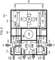
- the air conditioning apparatus 800 for the railroad vehicle includes (i) a first indoor fan 310a that facilitates the heat exchange between the first indoor heat exchanger 130a and the air of the passenger compartment 910 illustrated in FIG. 1 and (ii) a second indoor fan 310b that facilitates the heat exchange between the second indoor heat exchanger 130b and the air of the passenger compartment 910 illustrated in FIG. 1 .
- the first indoor fan 310a forms airflow AC by which a part of the return air RA passes through the first indoor heat exchanger 130a and then returns as the supply air SA to the passenger compartment 910 illustrated in FIG. 1 .
- the second indoor fan 310b forms airflow AC by which the rest of the return air RA passes through the second indoor heat exchanger 130b and then returns as the supply air SA to the passenger compartment 910 illustrated in FIG. 1 .
- the first indoor fan 310a is arranged at a position located downstream of the first indoor heat exchanger 130a with respect to a flow direction of the airflow AC formed thereby.
- the second indoor fan 310b is arranged at a position located downstream of the second indoor heat exchanger 130b with respect to a flow direction of the airflow AC formed thereby.
- the indoor heat exchanger 130 illustrated in FIG. 1 includes the first indoor heat exchanger 130a and the second indoor heat exchanger 130b. Further, the indoor fan 310 illustrated in FIG. 1 includes the first indoor fan 310a and the second indoor fan 310b.
- FIG. 1 illustrates a single airflow AC as the airflow AC formed by the first indoor fan 310a and the airflow AC formed by the second indoor fan 310b.
- the air conditioning apparatus 800 for the railroad vehicle includes a first heater 200a arranged in a path of the airflow AC formed by the first indoor fan 310a and a second heater 200b arranged in a path of the airflow AC formed by the second indoor fan 310b.
- the first heater 200a is arranged between the first indoor heat exchanger 130a and the first indoor fan 310a.
- the second heater 200b is arranged between the second indoor heat exchanger 130b and the second indoor fan 310b. Each of the first heater 200a and the second heater 200b heats the return air RA passing therethrough.
- the air conditioning apparatus 800 for the railroad vehicle includes an outdoor fan 320 that facilitates the heat exchange between (i) outside air that is air of the outside of the vehicle and (ii) each of the first outdoor heat exchanger 120a and the second outdoor heat exchanger 120b.
- the outdoor fan 320 forms non-illustrated airflow by passage of the outside air through the first outdoor heat exchanger 120a and the second outdoor heat exchanger 120b and return to the outside of the vehicle.
- the casing 700 internally defines, in addition to the indoor chamber 710 illustrated in FIG. 1 , (i) an outdoor chamber 720 in which the outdoor fan 320 is arranged and (ii) an exhaust chamber 730 in which the exhaust fan 330 is arranged.
- the indoor chamber 710, the outdoor chamber 720, and the exhaust chamber 730, are disposed so as to be hermetically sealed with respect to each other.
- the first compressor 110a, the second compressor 110b, the first outdoor heat exchanger 120a, the second outdoor heat exchanger 120b, the first accumulator 140a, and the second accumulator 140b, are arranged in the outdoor chamber 720, in addition to the outdoor fan 320.
- the indoor chamber 710 is divided into (i) a first return chamber 711 in which the first indoor heat exchanger 130a and the first heater 200a are arranged, (ii) a second return chamber 712 in which the second indoor heat exchanger 130b and the second heater 200b are arranged, and (iii) a supply chamber 713 in which the first indoor fan 310a and the second indoor fan 310b are arranged.
- the first return chamber 711 and the supply chamber 713 communicate through the first indoor fan 310a.
- the second return chamber 712 and the supply chamber 713 communicate through the second indoor fan 310b.
- the air conditioning apparatus 800 for the railroad vehicle includes (i) a fresh damper 431 that is a damper arranged in the first return chamber 711 of the indoor chamber 710 at a position through which the airflow AC passes and (ii) a fresh damper 432 that is a damper arranged in the second return chamber 712 of the indoor chamber 710 at a position through which the airflow AC passes.
- Each of the fresh dampers 431 and 432 is switchable between (i) an open state in which respective inflow of the outside air into the indoor chamber 710 from the exterior of the casing 700 or from the exterior of the vehicular compartment 910 illustrated in FIG. 1 is allowed and (ii) a closed state in which the inflow is prevented.
- the outside air taken in respectively through the fresh dampers 431 and 432 is called the fresh air FA.
- Each of the fresh damper 431 and 432 in the open state can adjust a flow rate of the fresh air FA.
- the carbon dioxide refrigerant is used as refrigerant in the refrigeration cycle device 100.
- the air conditioning apparatus 800 for the railroad vehicle according to the present embodiment is configured so as to enable, even in a case of leakage of the carbon dioxide refrigerant from the refrigeration cycle device 100, prompt and accurate detection of the leakage.
- this configuration is specifically described.
- the air conditioning apparatus 800 for the railroad vehicle includes a first gas sensor 510 disposed in a path of the airflow AC in the indoor chamber 710.
- the first gas sensor 510 is configured to detect a concentration of carbon dioxide gas in the path of the airflow AC at a position located downstream of the indoor heat exchanger 130.
- the first gas sensor 510 is arranged, in the path of the airflow AC formed by the first indoor fan 310a, at a position located downstream of the first indoor fan 310a. This enables more prompt detection of leakage of the carbon dioxide refrigerant from the refrigeration cycle device 100 than in a case of a configuration in which the first gas sensor 510 is arranged at a position located upstream of the first indoor fan 310a and the first indoor heat exchanger 130a.
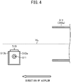
- the first gas sensor 510 is arranged in the supply chamber 713 at a position facing the first indoor fan 310a. More specifically, as illustrated in FIG. 4 , the first indoor fan 310a has an air outlet 311 configured to discharge the air included in the airflow AC, and the first gas sensor 510 is arranged at a position facing the air outlet 311.
- the first gas sensor 510 In the case as described above in which the first gas sensor 510 is arranged in the path of the airflow AC, a high wind velocity of the airflow AC that hits the first gas sensor 510 is a factor that leads to a decrease in accuracy of detection by the first gas sensor 510.
- the wind velocity of the airflow AC at the position facing the air outlet 311 of the first indoor fan 310a is higher than those of other positions in the path of the airflow AC.
- the first gas sensor 510 according to the present embodiment has a configuration for suppressing a decrease in accuracy of detection by preventing hitting by the airflow AC.
- this configuration is specifically described.
- FIG. 3 is an external perspective view of the first gas sensor 510.
- the first gas sensor 510 includes a sensing portion 511 configured to react in accordance with a concentration of carbon dioxide gas, a main body 512 configured to output a result of detection of the concentration of carbon dioxide gas based on the reaction by the sensing portion 511, and a windbreak plate 513 configured to prevent the airflow AC from hitting the sensing portion 511.
- the main body 512 is fixed to the casing 700 illustrated in FIG. 2 .
- the first gas sensor 510 includes a protrusion portion 514 that protrudes from the main body 512 in a vehicle width direction that is an intersection direction intersecting the airflow AC.
- This "vehicle width direction” indicates a width direction of the railroad vehicle 900 illustrated in FIG. 1 .
- the vehicle width direction is orthogonal to the airflow AC.
- the sensing portion 511 is disposed at the protrusion portion 514. That is, the sensing portion 511 is arranged at a position deviated from the main body 512 in a direction orthogonal to the airflow AC.
- the windbreak plate 513 includes a first windbreak plate 513a and a second windbreak plate 513b that each protrude from the main body 512 in the vehicle width direction.
- the first windbreak plate 513a and the second windbreak plate 513b face each other in the direction of the airflow AC.
- the sensing portion 511 is arranged between the first windbreak plate 513a and the second windbreak plate 513b with respect to the direction of the airflow AC.
- the first windbreak plate 513a that is a windbreak plate located upstream side among the first windbreak plate 513a and the second windbreak plate 513b with respect to a flow of the airflow AC is arranged between the sensing portion 511 and the first indoor fan 310a illustrated in FIG. 2 . Due to such configuration, the first windbreak plate 513a prevents the airflow AC from hitting the sensing portion 511. This leads to a decrease in the wind velocity of the airflow AC hitting the sensing portion 511 and also leads to appropriate stirring of the airflow AC at a position of the sensing portion 511. As a result, accuracy of detection by the first gas sensor 510 is improved.
- the second windbreak plate 513b that is a windbreak plate located downstream side among a pair of the first windbreak plate 513a and the second windbreak plate 513b with respect to the flow of the airflow AC also serves for the appropriate stirring of the airflow AC at the position of the sensing portion 511 and thus contributes to the improvement in the accuracy of detection by the first gas sensor 510.
- the second windbreak plate 513b may be omitted.
- the virtual line VL of FIG. 4 indicates a central position of the air outlet 311 of the first indoor fan 310a in the vertical direction.
- the first gas sensor 510 is arranged below the virtual line VL. That is, the sensing portion 511 of the first gas sensor 510 is arranged below the central position of the air outlet 311 in the vertical direction.
- the air conditioning apparatus 800 for the railroad vehicle includes a control device 600 configured to make, by using the result of detection by the first gas sensor 510, determination of whether leakage of the carbon dioxide refrigerant from the refrigeration cycle device 100 is occurring that is hereinafter referred to as the refrigerant leakage determination.
- the control device 600 in the case of determining that leakage of the carbon dioxide refrigerant is occurring, performs at least one of emergency control for suppressing an increase in concentration of the carbon dioxide gas in the passenger compartment 910 or alert control for issuing an alert indicating the occurrence of the leakage of the carbon dioxide refrigerant.
- the first windbreak plate 513a prevents the airflow AC from hitting the sensing portion 511, allowing the first gas sensor 510 to accurately detect a concentration of carbon dioxide gas due to leakage of the carbon dioxide refrigerant. In comparison to conventional techniques, this enables more improvement in accuracy of the refrigerant leakage determination made by the control device 600.
- the first windbreak plate 513a protrudes in the vehicle width direction with respect to the protrusion portion 514. Due to such configuration, the first windbreak plate 513a prevents the airflow AC from directly hitting the sensing portion 511. This enables further improvement in accuracy of detection by the first gas sensor 510.
- the second windbreak plate 513b also protrudes in the vehicle width direction with respect to the protrusion portion 514. Due to this, the pair of the first windbreak plate 513a and the second windbreak plate 513b causes stirring of the airflow AC at the position of the sensing portion 511. This configuration also contributes to the improvement in the accuracy of detection by the first gas sensor 510. However, the second windbreak plate 513b may be omitted, as described above.
- the control device 600 executes refrigerant leakage monitor processing in which the aforementioned refrigerant leakage determination is repeatedly made in real time.
- the refrigerant leakage monitor processing is described with reference to FIGS. 6 and 7 .
- the control device 600 firstly causes the first gas sensor 510 to start detection of the concentration of carbon dioxide gas (step S11). Thereafter, the first gas sensor 510 repeatedly detects the concentration of carbon dioxide gas in real time.
- control device 600 acquires a detection result Cs from the first gas sensor 510 (step S 12), and compares an increase rate of the detection result Cs and a predetermined threshold Th indicating the occurrence of leakage of the carbon dioxide refrigerant from the refrigeration cycle device 100 (step S13).
- the threshold Th is 10,000 [ppm/h] in the present embodiment, no particular limitation is placed on the threshold Th.
- the "increase rate of the detection result Cs” indicates (i) a difference between a value of a current detection result Cs and a value of a preceding detection result Cs or (ii) a physical quantity that is proportional to the difference.
- the "value of a preceding detection result Cs” means a value of the detection result Cs at a time one sampling period beforehand. An initial value of the detection result Cs is taken to be zero.
- step S13 When the increase rate of the detection result Cs is equal to or smaller than the threshold Th (NO in step S13), the control device 600 determines that leakage of the carbon dioxide refrigerant from the refrigeration cycle device 100 is not occurring. Then the control device 600 returns to step S12 in order to continue monitoring of whether leakage of the carbon dioxide refrigerant is occurring.
- the loop of step S 12 and step S13 is repeated at every sampling period of detection by the first gas sensor 510.
- the control device 600 determines that leakage of the carbon dioxide refrigerant from the refrigeration cycle device 100 is occurring. Then the control device 600 starts the emergency control for suppressing an increase in concentration of carbon dioxide gas in the passenger compartment 910 (step S 14).
- the emergency control is specifically described with reference to FIG. 7 .
- the control device 600 when air conditioning of the passenger compartment 910 is currently performed, the control device 600 firstly causes stoppage of the air conditioning (step S21). Specifically, the control device 600 causes stoppage of the first compressor 110a and the second compressor 110b that are illustrated in FIG. 2 . This stops circulation of the carbon dioxide refrigerant in the refrigeration cycle device 100, enabling suppression of worsening of the leakage of the carbon dioxide refrigerant. Further, the control device 600 also causes stoppage of the first indoor fan 310a, the second indoor fan 310b, and the outdoor fan 320 that are illustrated in FIG. 2 .
- control device 600 causes the exhaust fan 330 illustrated in FIG. 1 to operate in a state in which the return damper 410 illustrated in FIG. 1 is switched to the closed state and the supply damper 420 illustrated in FIG. 1 and the fresh dampers 431 and 432 illustrated in FIG. 2 are each switched to the open state (step S22).
- Causing the exhaust fan 330 to operate leads to exhausting of the exhaust air EA to the outside of the vehicle through the exhaust duct 940, as illustrated in FIG. 1 . Since the carbon dioxide gas existing in the passenger compartment 910 is also exhausted as the exhaust air EA, an increase in concentration of carbon dioxide gas in the passenger compartment 910 is suppressed.
- the exhaust fan 330 also serves to draw the fresh air FA illustrated in FIG. 2 into the passenger compartment 910. That is, the atmospheric pressure of the passenger compartment 910 decreases due to the exhausting of the exhaust air EA, and due to the decrease in the atmospheric pressure, the fresh air FA illustrated in FIG. 2 flows into the indoor chamber 710 through each of the fresh dampers 431 and 432 and flows into the passenger compartment 910 through the indoor chamber 710 and the supply damper 420 illustrated in FIG. 1 . Since the fresh air FA flows into the passenger compartment 910 in the aforementioned manner, the increase in the concentration of carbon dioxide gas in the passenger compartment 910 is suppressed.
- control device 600 reacquires the detection result Cs from the first gas sensor 510 (step S15), and determines whether the increase rate of the detection result Cs exceeds the threshold Th (step S16).
- step S 16 When the increase rate of the detection result Cs exceeds the threshold Th (YES in step S 16), since leakage of the carbon dioxide refrigerant from the refrigeration cycle device 100 is not yet ended, the control device 600 returns to step S15 in order to continue the emergency control.
- the loop of step S15 and step S16 is repeated at every sampling period of detection by the first gas sensor 510.
- step S 17 when the increase rate of the detection result Cs is equal to or smaller than the threshold Th (NO in step S 16), since the leakage of the carbon dioxide refrigerant from the refrigeration cycle device 100 can be deemed to be ended, the control device 600 ends the emergency control (step S17).
- control device 600 switches the supply damper 420 illustrated in FIG. 1 to the closed state and causes the exhaust fan 330 illustrated in FIG. 1 to stop.
- the return damper 410 illustrated in FIG. 1 may be switched to the open state, although maintaining in the closed state is preferable in order to disconnect the indoor chamber 710 and the passenger compartment 910.
- each of the fresh dampers 431 and 432 that are illustrated in FIG. 2 may be switched to the closed state, although maintaining in the open state is preferable.
- control device 600 does not restart the air conditioning until completion of repair of the refrigeration cycle device 100.
- the emergency control according to aforementioned Embodiment 3 includes causing the fresh air FA to flow into the passenger compartment through the fresh dampers 431 and 432, the fresh dampers 431 and 432 need not be switched to the open state by the emergency control.
- the emergency control includes causing the fresh air FA to flow into the passenger compartment through the fresh dampers 431 and 432, the fresh dampers 431 and 432 need not be switched to the open state by the emergency control.
- a specific example of such configuration is described.
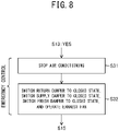
- FIG. 8 is a flowchart of emergency control according to the present embodiment.
- the control device 600 causes stoppage of the air conditioning (step S31), and then causes the exhaust fan 330 illustrated in FIG. 1 to operate in a state in which all of the return damper 410 and the supply damper 420 that are illustrated in FIG. 1 and the fresh dampers 431 and 432 illustrated in FIG. 2 are switched to the closed state (step S32).
- Switching the return damper 410 and the supply damper 420 to the closed state cuts off the communication between the indoor chamber 710 and the passenger compartment 910. Further, since the fresh dampers 431 and 432 are switched to the closed state, a flow of air from the indoor chamber 710 to the vehicle chamber 910 is less likely to be formed even upon a decrease in air pressure of the passenger compartment 910 that is caused by the exhaust fan 330.
- This configuration enables prevention of the carbon dioxide refrigerant leaked from the refrigeration cycle device 100 from flowing out from the indoor chamber 710 to the passenger compartment 910. Accordingly, an increase in the concentration of carbon dioxide gas in the passenger compartment 910 is suppressed.
- the outside air flows into the passenger compartment 910 through this intake duct.
- a non-illustrated window leading to the exterior is disposed in the passenger compartment 910
- the outside air flows into the passenger compartment 910 through this window.
- a non-illustrated entrance-exit door through which passengers get on and get off is arranged for the passenger compartment 910
- the outside air flows into the passenger compartment 910 through this entrance-exit door upon arrival of the railroad vehicle 900 at a station. Due to this, the concentration of carbon dioxide gas in the passenger compartment 910 is reduced.
- Embodiments 1-4 examples of configuration are described in which the determination of whether leakage of the carbon dioxide refrigerant is occurring is made by using the result of the detection by the first gas sensor 510.
- a second gas sensor may further be arranged at a position located upstream of the indoor heat exchanger 130 with respect to the flow direction of the airflow AC, and the determination of whether leakage of the carbon dioxide refrigerant is occurring may be made by using the a result of detection by the first gas sensor 510 and a result of detection by the second gas sensor.
- a specific example of such configuration is described.
- an air conditioning apparatus 800 for a railroad vehicle includes, in addition to the first gas sensor 510, a second gas sensor 520 arranged in the first return chamber 711.
- the second gas sensor 520 is configured to detect a concentration of carbon dioxide gas, in the path of the airflow AC formed by the first indoor fan 310a, at a position located upstream of the first indoor heat exchanger 130a.
- the second gas sensor 520 has a configuration that is the same as that of the first gas sensor 510 illustrated in FIG. 3 or FIG. 5 .
- control device 600 illustrated in FIG. 1 executes, by using a result of detection by the first gas sensor 510 and a result of detection by the second gas sensor 520, the refrigerant leakage monitor processing in which the aforementioned refrigerant leakage determination is repeatedly made in real time.
- the refrigerant leakage monitor processing in which the aforementioned refrigerant leakage determination is repeatedly made in real time.
- the control device 600 firstly causes the first gas sensor 510 and the second gas sensor 520 to start detection of the concentration of carbon dioxide gas (step S41). Thereafter, each of the first gas sensor 510 and the second gas sensor 520 repeatedly detects the concentration of carbon dioxide gas in real time at a corresponding position.
- the sampling period of detection by the first gas sensor 510 and the second gas sensor 520 is preferably equal to or less than fifteen seconds, more preferably equal to or less than ten seconds, and still more preferably equal to or less than three seconds.
- control device 600 acquires a detection result Cs from the first gas sensor 510 and acquires a detection result Cr from the second gas sensor 520 (step S42),
- control device 600 subtracts the detection result Cr of the second gas sensor 520 from the detection result Cs of the first gas sensor 510, and determines, by comparing a value of Cs - Cr that is a result of the subtraction and a predetermined first threshold Th1, whether leakage of the carbon dioxide refrigerant from the refrigeration cycle device 100 is occurring (step S43).
- the control device 600 acquires each of the detection result Cs of the first gas sensor 510 and the detection result Cr of the second gas sensor 520 in real time, and calculates a difference between the detection results Cs and Cr that are detected at the same time.
- the detection result Cs of the first gas sensor 510 further contains a concentration of carbon dioxide gas that is derived from the leaked carbon dioxide refrigerant.
- the concentration of carbon dioxide gas that is derived from the leaked carbon dioxide refrigerant is not yet reflected in the detection result Cr of the second gas sensor 520 disposed at the position located upstream of the first indoor heat exchanger 130a and the first refrigerant piping 150a. Accordingly, the difference Cs - Cr becomes a large value.
- control device 600 can detect leakage of the carbon dioxide refrigerant by comparing the value of the difference Cs - Cr with the first threshold Th1 that indicates an increase in concentration of carbon dioxide gas in air included in the airflow AC due to the leakage of the carbon dioxide refrigerant.
- the control device 600 determines that leakage of the carbon dioxide refrigerant from the refrigeration cycle device 100 is not occurring.
- step S42 the control device 600 returns to step S42 in order to continue monitoring of whether leakage of the carbon dioxide refrigerant is occurring.
- the loop of step S42 and step S43 is repeated at every sampling period of detection by the first gas sensor 510 and detection by the second gas sensor 520.
- the control device 600 determines that leakage of the carbon dioxide refrigerant from the refrigeration cycle device 100 is occurring.
- control device 600 starts the emergency control for suppressing an increase in concentration of carbon dioxide gas in the passenger compartment 910 (step S44).
- Specific content of this emergency control is the same as that indicated in FIG. 7 or that indicated in FIG. 8 .
- control device 600 acquires the detection result Cs from the first gas sensor 510 (step S45) and compares the detection result Cs of the first gas sensor 510 and a predetermined second threshold Th2 (step S46).
- the second threshold Th2 is a value that is sufficiently small as to allow the leakage of the carbon dioxide refrigerant from the refrigeration cycle device 100 to be considered to be ended.
- step S46 indicates a determination that is hereinafter referred to as the end determination and is a determination of whether to end the emergency control.
- the control device 600 makes the end determination by using, among the detection result Cs of the first gas sensor 510 and the detection result Cr of the second gas sensor 520, only the detection result Cs of the first gas sensor 510.
- step S46 the return damper 410 is in a state of being switched to the closed state, and therefore almost no airflow AC is formed around the second gas sensor 520, and the detection result Cr of the second gas sensor 520 is unlikely to change even after ending of leakage of the carbon dioxide refrigerant.
- the fresh air FA passed through the indoor heat exchanger 130 flows through the position of the first gas sensor 510, whether leakage of the carbon dioxide refrigerant is ended is detectable by using the detection result Cs of the first gas sensor 510.
- step S46 When the detection result Cs of the first gas sensor 510 exceeds the second threshold Th2 (YES in step S46), since the leakage of the carbon dioxide refrigerant from the refrigeration cycle device 100 is not yet ended, the control device 600 returns to step S45 in order to continue the emergency control.
- the loop of step S45 and step S46 is repeated at every sampling period of detection by the first gas sensor 510.
- step S47 when the detection result Cs of the first gas sensor 510 is equal to or smaller than the second threshold Th2 (NO in step S46), since the leakage of the carbon dioxide refrigerant from the refrigeration cycle device 100 can be deemed to be ended, the control device 600 ends the emergency control (step S47).
- the detection result Cs of the first gas sensor 510 and the detection result Cr of the second gas sensor 520 indicate the same value or indicate close values, and in contrast, in the case of occurrence of leakage of the carbon dioxide refrigerant from the refrigeration cycle device 100, the detection result Cs of the first gas sensor 510 at the time of the occurrence of the leakage becomes larger than the detection result Cr of the second gas sensor 520 at the time of the occurrence of the leakage. Due to this, the control device 600 can accurately detect leakage of carbon dioxide gas by using the value of the difference Cs - Cr.
- the control device 600 can cancel out from the detection result Cs of the first gas sensor 510 the concentration of carbon dioxide gas derived from expired human breath existing in the passenger compartment 910, by subtracting the detection result Cr of the second gas sensor 520 from the detection result Cs of the first gas sensor 510. That is, even in a case in which concentration of carbon dioxide gas derived from the expired human breath changes in accordance with a change in a passenger load factor of the passenger compartment 910, this change is unlikely to produce an effect on Cs - Cr that is the difference between the detection result Cs of the first gas sensor 510 and the detection result Cr of the second gas sensor 520.
- the physical quantity used for the determination is not limited to the difference Cs - Cr.
- control device 600 determines, by comparing an increase rate of the difference Cs - Cr and a predetermined third threshold ThA, whether leakage of the carbon dioxide refrigerant from the refrigeration cycle device 100 is occurring (step S51).
- the "increase rate of the difference Cs - Cr" indicates (i) a difference between a value of a current difference Cs - Cr and a value of a preceding difference Cs - Cr or (ii) a physical quantity that is proportional to the difference.
- the "value of a preceding difference Cs - Cr” means a value of the difference Cs - Cr at a time one sampling period beforehand.
- the increase rate of the difference Cs - Cr becomes zero or a value close to zero. Conversely, in the case of occurrence of leakage of the carbon dioxide refrigerant from the refrigeration cycle device 100, the increase rate of the difference Cs - Cr becomes a large value, since this rate represents severity of the leakage of the carbon dioxide refrigerant.
- step S51 When the increase rate of the difference Cs - Cr is larger than or equal to the third threshold ThA indicating the occurrence of leakage of the carbon dioxide refrigerant from the refrigeration cycle device 100 (YES in step S51), the control device 600 proceeds to step S44.
- step S51 when the increase rate of the difference Cs - Cr is smaller than the third threshold ThA (NO in step S51), the control device 600 returns to step S42 due to the inability to say in this case that leakage of the carbon dioxide refrigerant from the refrigeration cycle device 100 is occurring.
- control device 600 determines, by comparison as to whether an increase rate of Cs is equal to or smaller than a predetermined fourth threshold ThB, whether the leakage of the of the carbon dioxide refrigerant is ended (step S52).
- the "increase rate of Cs” indicates (i) a difference between a value of a current Cs and a value of a preceding Cs or (ii) a physical quantity that is proportional to the difference.
- the "value of a preceding Cs” means a value of Cs at a time one sampling period beforehand.
- the control device 600 proceeds to step S47 when the increase rate of Cs is equal to or smaller than the fourth threshold ThB that is a negative value indicating that leakage of the carbon dioxide refrigerant is ending (YES in step S52), or returns to step S45 when the gradient of Cs is larger than the fourth threshold ThB (NO in step S52).
- the fourth threshold ThB that is a negative value indicating that leakage of the carbon dioxide refrigerant is ending
- FIG. 9 illustrates an example of configuration in which the second gas sensor 520 is arranged in the indoor chamber 710, the second gas sensor 520 may be arranged in the passenger compartment 910.
- the second gas sensor 520 is arranged inside the passenger compartment 910 at a location other than a location that is directly hit by the supply air SA. Since specific gravity of carbon dioxide gas is larger than specific gravity of air, the second gas sensor 520 may be arranged on the floor of the passenger compartment 910, at a lower part of a seat, or the like. Other configuration and functional effects are similar to those of Embodiment 5.
- FIGS. 3-5 relating to aforementioned Embodiments 1 and 2 illustrate the second windbreak plate 513b facing the first windbreak plate 513a, the second windbreak plate 513b may be omitted.
- Embodiment 5 describes making the determination of whether leakage of the carbon dioxide refrigerant is occurring based on the value of the difference Cs - Cr and aforementioned Embodiment 6 describes making the determination of whether leakage of the carbon dioxide refrigerant is occurring based on the increase rate of the difference Cs - Cr
- the physical quantity used for the determination of whether leakage of the carbon dioxide refrigerant is occurring is not limited to the difference Cs - Cr and increase rate of the difference Cs - Cr. Any physical quantity dependent on the difference Cs - Cr is usable for the determination of whether leakage of the carbon dioxide refrigerant is occurring.
- the railroad vehicle as used herein is not limited to a train but includes a bullet train, a monorail, and other vehicles that travel along a track. Further, the vehicle in which the casing 700 is installed is not limited to a railroad vehicle and may be a bus or other automobile-type vehicle.
- An air conditioning apparatus for a vehicle can be utilized for air conditioning of a vehicular compartment defined in a vehicle for human occupancy.
Landscapes
- Engineering & Computer Science (AREA)
- Mechanical Engineering (AREA)
- Physics & Mathematics (AREA)
- Thermal Sciences (AREA)
- General Engineering & Computer Science (AREA)
- Air-Conditioning For Vehicles (AREA)
- Air Conditioning Control Device (AREA)
Abstract
Description
- The present disclosure relates to an air conditioning apparatus for a vehicle.
- As disclosed in Patent Literature 1, an air conditioning apparatus for a vehicle is known that performs air conditioning of a vehicular compartment by a refrigeration cycle device that employs carbon dioxide as a refrigerant. The refrigeration cycle device includes an indoor heat exchanger that performs heat exchange between the refrigerant and air of the vehicular compartment.
- Additionally, the air conditioning apparatus for a vehicle includes (i) an indoor fan that forms airflow passing through the indoor heat exchanger, (ii) a gas sensor that detects a concentration of carbon dioxide gas at a position located downstream of the indoor heat exchanger with respect to a direction in which the airflow flows, and (iii) a control device that determines, by using a result of the detection by the gas sensor, whether leakage of the refrigerant from the indoor exchanger is occurring.
- Patent Literature 1: International Publication No.
WO 00/59748 - According to the configuration of the aforementioned air conditioning apparatus for a vehicle, the airflow after passage through the indoor heat exchanger directly hits the gas sensor. This is a factor that leads to a decrease in accuracy of the detection by the gas sensor.
- An objective of the present disclosure is to provide an air conditioning apparatus, for a vehicle, that enables high-accuracy detection of the concentration of carbon dioxide gas due to leakage of refrigerant.
- To achieve the aforementioned objective, an air conditioning apparatus for a vehicle according to the present disclosure includes (i) a casing defining an indoor chamber communicating with a vehicular compartment of the vehicle, (ii) an indoor heat exchanger arranged in the indoor chamber and having an interior for flow therethrough of a refrigerant containing carbon dioxide, (iii) a cooperation device included in, together with the indoor heat exchanger, a refrigeration cycle device for circulation therethrough of the refrigerant, (iv) an indoor fan that is arranged in the indoor chamber and forms airflow by air flowing from the vehicular compartment into the indoor chamber, passing through the indoor heat exchanger, and flowing out to return to the vehicular compartment, and (v) a first gas sensor that detects a concentration of carbon dioxide gas in a path of the airflow at a position located downstream of the indoor heat exchanger. The first gas sensor includes (i) a sensing portion that reacts in accordance with the concentration of the carbon dioxide gas and (ii) a windbreak plate that prevents the airflow from hitting the sensing portion.
- According to the aforementioned configuration, the windbreak plate can prevent the airflow from hitting the sensing portion, allowing the first gas sensor to accurately detect the concentration of the carbon dioxide gas due to leakage of the refrigerant.
-
-
FIG. 1 is a schematic diagram illustrating a part of configuration of an air conditioning apparatus for a railroad vehicle according to Embodiment 1; -
FIG. 2 is a plan view illustrating an interior of a casing according to Embodiment 1; -
FIG. 3 is an external perspective view of a first gas sensor according to Embodiment 1; -
FIG. 4 is a schematic diagram illustrating a positional relationship between the first gas sensor and a first indoor fan according to Embodiment 1; -
FIG. 5 is a schematic diagram illustrating configuration of a first gas sensor according to Embodiment 2; -
FIG. 6 is a flowchart of refrigerant leakage monitor processing according to Embodiment 3; -
FIG. 7 is a flowchart of emergency control according to Embodiment 3; -
FIG. 8 is a flowchart of emergency control according to Embodiment 4; -
FIG. 9 is a plan view illustrating an interior of a casing according to Embodiment 5; -
FIG. 10 is a flowchart of refrigerant leakage monitor processing according to Embodiment 5; -
FIG. 11 is a flowchart of refrigerant leakage monitor processing according to Embodiment 6; and -
FIG. 12 is a schematic diagram illustrating a part of configuration of an air conditioning apparatus for a railroad vehicle according to Embodiment 7. - Hereinafter, air conditioning apparatuses for a railroad vehicle according to Embodiments 1-7, in which the vehicle is a railroad vehicle, are described with reference to the drawings. In the drawings, components that are the same or equivalent are assigned the same reference sign.
-
FIG. 1 is a schematic diagram illustrating a part of configuration of anair conditioning apparatus 800 for a railroad vehicle according to the present embodiment. Theair conditioning apparatus 800 for the railroad vehicle performs air conditioning of apassenger compartment 910 that is a vehicular compartment defined in arailroad vehicle 900 for human occupancy. - The
air conditioning apparatus 800 for the railroad vehicle includes anindoor heat exchanger 130 having an interior for flow therethrough of a refrigerant containing carbon dioxide that is hereinafter referred to as the "carbon dioxide refrigerant". Theindoor heat exchanger 130 is a part of arefrigeration cycle device 100 that provides a refrigeration cycle by using the carbon dioxide refrigerant. - A refrigerant that contains carbon dioxide as main component, more specifically, a refrigerant corresponding to the refrigerant number "R-744" and having 99.9 % or more carbon dioxide purity, is preferable as the carbon dioxide refrigerant, from the viewpoint of non-combustibility and a low global warming potential.
- Furthermore, the
air conditioning apparatus 800 for the railroad vehicle includes acasing 700 that defines anindoor chamber 710 that is a space in which theindoor heat exchanger 130 is arranged. Theindoor chamber 710 communicates with thepassenger compartment 910. - Furthermore, the
air conditioning apparatus 800 for the railroad vehicle includes anindoor fan 310 arranged in theindoor chamber 710. Theindoor fan 310 forms airflow AC by air flowing from thepassenger compartment 910 into theindoor chamber 710, passing through theindoor heat exchanger 130, and flowing out to return to thepassenger compartment 910. - Hereinafter, air that is included in the airflow AC and flows from the
passenger compartment 910 into theindoor chamber 710 to theindoor heat exchanger 130 is called the return air RA. Additionally, air that flows out from theindoor chamber 710 to thepassenger compartment 910 after passage through theindoor heat exchanger 130 is called the supply air SA. - The return air RA passes through a
return duct 920 that is a duct communicating with thepassenger compartment 910, and flows into theindoor chamber 710. The supply air SA passes through asupply duct 930 that is an additional duct communicating with thepassenger compartment 910, and flows out from theindoor chamber 710 to thepassenger compartment 910. - Furthermore, the
air conditioning apparatus 800 for the railroad vehicle includes (i) areturn damper 410 that is a damper arranged at a boundary portion between thereturn duct 920 and theindoor chamber 710 and (ii) asupply damper 420 that is a damper arranged at a boundary portion between thesupply duct 930 and theindoor chamber 710. - The
return damper 410 is switchable between (i) an open state in which inflow of air forming the airflow AC, that is, the return air RA, from thepassenger compartment 910 into theindoor chamber 710, is allowed, and (ii) a closed state in which the inflow is prevented. Thereturn damper 410 in the open state can adjust a flow rate of the return air RA. - The
supply damper 420 is switchable between (i) an open state in which outflow of the airflow AC from theindoor chamber 710 to thepassenger compartment 910 is allowed and (ii) a closed state in which the outflow is prevented. Thesupply damper 420 in the open state can adjust a flow rate of the supply air SA. - Furthermore, the
air conditioning apparatus 800 for the railroad vehicle includes anexhaust fan 330 that exhausts air of thepassenger compartment 910 to an outside of the vehicle. This "outside of the vehicle" indicates an exterior of therailroad vehicle 900 and thecasing 700. - Hereinafter, air that is exhausted by the
exhaust fan 330 from thepassenger compartment 910 to the outside of the vehicle is called the exhaust air EA. The exhaust air EA is exhausted to the outside of the vehicle through anexhaust duct 940 that is a duct communicating with thepassenger compartment 910. Theexhaust duct 940 is a duct that is arranged independently of thereturn duct 920 and thesupply duct 930. - For easy understanding of functions of the
air conditioning apparatus 800 for the railroad vehicle,FIG. 1 illustrates positions and extension directions of thereturn duct 920, thesupply duct 930, theexhaust duct 940, and thecasing 700 that are different from actual positions and extension directions thereof. Thecasing 700 may be arranged on a roof of therailroad vehicle 900 or may be arranged under a floor of therailroad vehicle 900. - Next, specific arrangement of components in the
casing 700 is described with reference toFIG. 2 . - As illustrated in
FIG. 2 , therefrigeration cycle device 100 housed in thecasing 700 includes a firstrefrigeration cycle device 100a that provides a refrigeration cycle and a secondrefrigeration cycle device 100b that provides a refrigeration cycle independent of the firstrefrigeration cycle device 100a. - The first
refrigeration cycle device 100a includes (i) afirst compressor 110a that compresses the carbon dioxide refrigerant, (ii) a firstoutdoor heat exchanger 120a that condenses the compressed carbon dioxide refrigerant, (iii) a non-illustrated first expander that expands the condensed carbon dioxide refrigerant, (iv) a firstindoor heat exchanger 130a that evaporates the expanded carbon dioxide refrigerant, and (v) afirst accumulator 140a that separates liquid from the carbon dioxide refrigerant after passage through the firstindoor heat exchanger 130a and causes gas to return to thefirst compressor 110a. - Furthermore, the first
refrigeration cycle device 100a includesfirst refrigerant piping 150a having an interior for flow therethrough of the carbon dioxide refrigerant. Thefirst refrigerant piping 150a provides, by connecting thefirst compressor 110a, the firstoutdoor heat exchanger 120a, the first expander, the firstindoor heat exchanger 130a, and thefirst accumulator 140a, a closed loop in which the carbon dioxide refrigerant flows. - The
first compressor 110a, the firstoutdoor heat exchanger 120a, the first expander, thefirst accumulator 140a, and the firstrefrigerant piping 150a, are cooperation devices that are included in the firstrefrigeration cycle device 100a together with the firstindoor heat exchanger 130a. - The second
refrigeration cycle device 100b includes (i) asecond compressor 110b that compresses the carbon dioxide refrigerant, (ii) a secondoutdoor heat exchanger 120b that condenses the compressed carbon dioxide refrigerant, (iii) a non-illustrated second expander that expands the condensed carbon dioxide refrigerant, (iv) a secondindoor heat exchanger 130b that evaporates the expanded carbon dioxide refrigerant, and (v) asecond accumulator 140b that separates liquid from the carbon dioxide refrigerant after passage through the secondindoor heat exchanger 130b and causes gas to return to thesecond compressor 110b. - Furthermore, the second
refrigeration cycle device 100b includes secondrefrigerant piping 150b having an interior for flow therethrough of the carbon dioxide refrigerant. The secondrefrigerant piping 150b provides, by connecting thesecond compressor 110b, the secondoutdoor heat exchanger 120b, the second expander, the secondindoor heat exchanger 130b, and thesecond accumulator 140b, a closed loop in which the carbon dioxide refrigerant flows. - The
second compressor 110b, the secondoutdoor heat exchanger 120b, the second expander, thesecond accumulator 140b, and the secondrefrigerant piping 150b, are cooperation devices that are included in the secondrefrigeration cycle device 100b together with the secondindoor heat exchanger 130b. - Furthermore, the
air conditioning apparatus 800 for the railroad vehicle includes (i) a firstindoor fan 310a that facilitates the heat exchange between the firstindoor heat exchanger 130a and the air of thepassenger compartment 910 illustrated inFIG. 1 and (ii) a secondindoor fan 310b that facilitates the heat exchange between the secondindoor heat exchanger 130b and the air of thepassenger compartment 910 illustrated inFIG. 1 . - The first
indoor fan 310a forms airflow AC by which a part of the return air RA passes through the firstindoor heat exchanger 130a and then returns as the supply air SA to thepassenger compartment 910 illustrated inFIG. 1 . The secondindoor fan 310b forms airflow AC by which the rest of the return air RA passes through the secondindoor heat exchanger 130b and then returns as the supply air SA to thepassenger compartment 910 illustrated inFIG. 1 . - The first
indoor fan 310a is arranged at a position located downstream of the firstindoor heat exchanger 130a with respect to a flow direction of the airflow AC formed thereby. The secondindoor fan 310b is arranged at a position located downstream of the secondindoor heat exchanger 130b with respect to a flow direction of the airflow AC formed thereby. - The
indoor heat exchanger 130 illustrated inFIG. 1 includes the firstindoor heat exchanger 130a and the secondindoor heat exchanger 130b. Further, theindoor fan 310 illustrated inFIG. 1 includes the firstindoor fan 310a and the secondindoor fan 310b. For easy understanding,FIG. 1 illustrates a single airflow AC as the airflow AC formed by the firstindoor fan 310a and the airflow AC formed by the secondindoor fan 310b. - Furthermore, the
air conditioning apparatus 800 for the railroad vehicle includes afirst heater 200a arranged in a path of the airflow AC formed by the firstindoor fan 310a and asecond heater 200b arranged in a path of the airflow AC formed by the secondindoor fan 310b. - The
first heater 200a is arranged between the firstindoor heat exchanger 130a and the firstindoor fan 310a. Thesecond heater 200b is arranged between the secondindoor heat exchanger 130b and the secondindoor fan 310b. Each of thefirst heater 200a and thesecond heater 200b heats the return air RA passing therethrough. - Furthermore, the
air conditioning apparatus 800 for the railroad vehicle includes anoutdoor fan 320 that facilitates the heat exchange between (i) outside air that is air of the outside of the vehicle and (ii) each of the firstoutdoor heat exchanger 120a and the secondoutdoor heat exchanger 120b. Theoutdoor fan 320 forms non-illustrated airflow by passage of the outside air through the firstoutdoor heat exchanger 120a and the secondoutdoor heat exchanger 120b and return to the outside of the vehicle. - The
casing 700 internally defines, in addition to theindoor chamber 710 illustrated inFIG. 1 , (i) anoutdoor chamber 720 in which theoutdoor fan 320 is arranged and (ii) anexhaust chamber 730 in which theexhaust fan 330 is arranged. Theindoor chamber 710, theoutdoor chamber 720, and theexhaust chamber 730, are disposed so as to be hermetically sealed with respect to each other. - The
first compressor 110a, thesecond compressor 110b, the firstoutdoor heat exchanger 120a, the secondoutdoor heat exchanger 120b, thefirst accumulator 140a, and thesecond accumulator 140b, are arranged in theoutdoor chamber 720, in addition to theoutdoor fan 320. - Furthermore, the
indoor chamber 710 is divided into (i) afirst return chamber 711 in which the firstindoor heat exchanger 130a and thefirst heater 200a are arranged, (ii) asecond return chamber 712 in which the secondindoor heat exchanger 130b and thesecond heater 200b are arranged, and (iii) asupply chamber 713 in which the firstindoor fan 310a and the secondindoor fan 310b are arranged. - The
first return chamber 711 and thesupply chamber 713 communicate through the firstindoor fan 310a. Thesecond return chamber 712 and thesupply chamber 713 communicate through the secondindoor fan 310b. - Furthermore, the
air conditioning apparatus 800 for the railroad vehicle includes (i) afresh damper 431 that is a damper arranged in thefirst return chamber 711 of theindoor chamber 710 at a position through which the airflow AC passes and (ii) afresh damper 432 that is a damper arranged in thesecond return chamber 712 of theindoor chamber 710 at a position through which the airflow AC passes. - Each of the
fresh dampers indoor chamber 710 from the exterior of thecasing 700 or from the exterior of thevehicular compartment 910 illustrated inFIG. 1 is allowed and (ii) a closed state in which the inflow is prevented. Hereinafter, the outside air taken in respectively through thefresh dampers fresh damper - Next, configuration for detecting leakage of the carbon dioxide refrigerant from the
refrigeration cycle device 100 is described. - As described above, the carbon dioxide refrigerant is used as refrigerant in the
refrigeration cycle device 100. Thus, theair conditioning apparatus 800 for the railroad vehicle according to the present embodiment is configured so as to enable, even in a case of leakage of the carbon dioxide refrigerant from therefrigeration cycle device 100, prompt and accurate detection of the leakage. Hereinafter, this configuration is specifically described. - As illustrated in
FIG. 1 , in order to detect leakage of the carbon dioxide refrigerant from therefrigeration cycle device 100, theair conditioning apparatus 800 for the railroad vehicle includes afirst gas sensor 510 disposed in a path of the airflow AC in theindoor chamber 710. Thefirst gas sensor 510 is configured to detect a concentration of carbon dioxide gas in the path of the airflow AC at a position located downstream of theindoor heat exchanger 130. - Specifically, as illustrated in
FIG. 2 , thefirst gas sensor 510 is arranged, in the path of the airflow AC formed by the firstindoor fan 310a, at a position located downstream of the firstindoor fan 310a. This enables more prompt detection of leakage of the carbon dioxide refrigerant from therefrigeration cycle device 100 than in a case of a configuration in which thefirst gas sensor 510 is arranged at a position located upstream of the firstindoor fan 310a and the firstindoor heat exchanger 130a. - Specifically, the
first gas sensor 510 is arranged in thesupply chamber 713 at a position facing the firstindoor fan 310a. More specifically, as illustrated inFIG. 4 , the firstindoor fan 310a has anair outlet 311 configured to discharge the air included in the airflow AC, and thefirst gas sensor 510 is arranged at a position facing theair outlet 311. - In the case as described above in which the
first gas sensor 510 is arranged in the path of the airflow AC, a high wind velocity of the airflow AC that hits thefirst gas sensor 510 is a factor that leads to a decrease in accuracy of detection by thefirst gas sensor 510. In particular, the wind velocity of the airflow AC at the position facing theair outlet 311 of the firstindoor fan 310a is higher than those of other positions in the path of the airflow AC. Thus, thefirst gas sensor 510 according to the present embodiment has a configuration for suppressing a decrease in accuracy of detection by preventing hitting by the airflow AC. Hereinafter, this configuration is specifically described. -
FIG. 3 is an external perspective view of thefirst gas sensor 510. Thefirst gas sensor 510 includes asensing portion 511 configured to react in accordance with a concentration of carbon dioxide gas, amain body 512 configured to output a result of detection of the concentration of carbon dioxide gas based on the reaction by thesensing portion 511, and awindbreak plate 513 configured to prevent the airflow AC from hitting thesensing portion 511. - The
main body 512 is fixed to thecasing 700 illustrated inFIG. 2 . Further, thefirst gas sensor 510 includes aprotrusion portion 514 that protrudes from themain body 512 in a vehicle width direction that is an intersection direction intersecting the airflow AC. This "vehicle width direction" indicates a width direction of therailroad vehicle 900 illustrated inFIG. 1 . At the position facing the air outlet of the firstindoor fan 310a illustrated inFIG. 2 , the vehicle width direction is orthogonal to the airflow AC. - The
sensing portion 511 is disposed at theprotrusion portion 514. That is, thesensing portion 511 is arranged at a position deviated from themain body 512 in a direction orthogonal to the airflow AC. Thewindbreak plate 513 includes afirst windbreak plate 513a and asecond windbreak plate 513b that each protrude from themain body 512 in the vehicle width direction. Thefirst windbreak plate 513a and thesecond windbreak plate 513b face each other in the direction of the airflow AC. Thesensing portion 511 is arranged between thefirst windbreak plate 513a and thesecond windbreak plate 513b with respect to the direction of the airflow AC. - The
first windbreak plate 513a that is a windbreak plate located upstream side among thefirst windbreak plate 513a and thesecond windbreak plate 513b with respect to a flow of the airflow AC is arranged between the sensingportion 511 and the firstindoor fan 310a illustrated inFIG. 2 . Due to such configuration, thefirst windbreak plate 513a prevents the airflow AC from hitting thesensing portion 511. This leads to a decrease in the wind velocity of the airflow AC hitting thesensing portion 511 and also leads to appropriate stirring of the airflow AC at a position of thesensing portion 511. As a result, accuracy of detection by thefirst gas sensor 510 is improved. - Furthermore, the
second windbreak plate 513b that is a windbreak plate located downstream side among a pair of thefirst windbreak plate 513a and thesecond windbreak plate 513b with respect to the flow of the airflow AC also serves for the appropriate stirring of the airflow AC at the position of thesensing portion 511 and thus contributes to the improvement in the accuracy of detection by thefirst gas sensor 510. However, thesecond windbreak plate 513b may be omitted. - A positional relationship between the
first gas sensor 510 and the firstindoor fan 310a with respect to a vertical direction is described with reference toFIG. 4 . The virtual line VL ofFIG. 4 indicates a central position of theair outlet 311 of the firstindoor fan 310a in the vertical direction. Thefirst gas sensor 510 is arranged below the virtual line VL. That is, thesensing portion 511 of thefirst gas sensor 510 is arranged below the central position of theair outlet 311 in the vertical direction. - Since carbon dioxide gas is heavier than air, in a case in which the airflow AC includes carbon dioxide gas due to leakage of the carbon dioxide refrigerant, this carbon dioxide gas tries to move downward. Accordingly, arranging the
sensing portion 511 below the central position of theair outlet 311 in the vertical direction enables directing a large portion of the carbon dioxide gas in the air flow AC toward thesensing portion 511. This allows thefirst gas sensor 510 to accurately detect a concentration of carbon dioxide gas. - Again with reference to
FIG. 1 , theair conditioning apparatus 800 for the railroad vehicle includes acontrol device 600 configured to make, by using the result of detection by thefirst gas sensor 510, determination of whether leakage of the carbon dioxide refrigerant from therefrigeration cycle device 100 is occurring that is hereinafter referred to as the refrigerant leakage determination. Thecontrol device 600, in the case of determining that leakage of the carbon dioxide refrigerant is occurring, performs at least one of emergency control for suppressing an increase in concentration of the carbon dioxide gas in thepassenger compartment 910 or alert control for issuing an alert indicating the occurrence of the leakage of the carbon dioxide refrigerant. - As described above, according to the present embodiment, the
first windbreak plate 513a prevents the airflow AC from hitting thesensing portion 511, allowing thefirst gas sensor 510 to accurately detect a concentration of carbon dioxide gas due to leakage of the carbon dioxide refrigerant. In comparison to conventional techniques, this enables more improvement in accuracy of the refrigerant leakage determination made by thecontrol device 600. - Hereinafter, a preferable modified example of configuration of the
first gas sensor 510 is described. - As illustrated in
FIG. 5 , in afirst gas sensor 510 according to the present embodiment, thefirst windbreak plate 513a protrudes in the vehicle width direction with respect to theprotrusion portion 514. Due to such configuration, thefirst windbreak plate 513a prevents the airflow AC from directly hitting thesensing portion 511. This enables further improvement in accuracy of detection by thefirst gas sensor 510. - Furthermore, the
second windbreak plate 513b also protrudes in the vehicle width direction with respect to theprotrusion portion 514. Due to this, the pair of thefirst windbreak plate 513a and thesecond windbreak plate 513b causes stirring of the airflow AC at the position of thesensing portion 511. This configuration also contributes to the improvement in the accuracy of detection by thefirst gas sensor 510. However, thesecond windbreak plate 513b may be omitted, as described above. - Hereinafter, a specific example of operations by the
control device 600 illustrated inFIG. 1 is described. Thecontrol device 600 executes refrigerant leakage monitor processing in which the aforementioned refrigerant leakage determination is repeatedly made in real time. Hereinafter, the refrigerant leakage monitor processing is described with reference toFIGS. 6 and7 . - As illustrated in
FIG. 6 , thecontrol device 600 firstly causes thefirst gas sensor 510 to start detection of the concentration of carbon dioxide gas (step S11). Thereafter, thefirst gas sensor 510 repeatedly detects the concentration of carbon dioxide gas in real time. - Then the
control device 600 acquires a detection result Cs from the first gas sensor 510 (step S 12), and compares an increase rate of the detection result Cs and a predetermined threshold Th indicating the occurrence of leakage of the carbon dioxide refrigerant from the refrigeration cycle device 100 (step S13). Although the threshold Th is 10,000 [ppm/h] in the present embodiment, no particular limitation is placed on the threshold Th. - The "increase rate of the detection result Cs" indicates (i) a difference between a value of a current detection result Cs and a value of a preceding detection result Cs or (ii) a physical quantity that is proportional to the difference. The "value of a preceding detection result Cs" means a value of the detection result Cs at a time one sampling period beforehand. An initial value of the detection result Cs is taken to be zero.
- When the increase rate of the detection result Cs is equal to or smaller than the threshold Th (NO in step S13), the
control device 600 determines that leakage of the carbon dioxide refrigerant from therefrigeration cycle device 100 is not occurring. Then thecontrol device 600 returns to step S12 in order to continue monitoring of whether leakage of the carbon dioxide refrigerant is occurring. The loop of step S 12 and step S13 is repeated at every sampling period of detection by thefirst gas sensor 510. - Conversely, when the increase rate of the detection result Cs exceeds the threshold Th (YES in step S13), the
control device 600 determines that leakage of the carbon dioxide refrigerant from therefrigeration cycle device 100 is occurring. Then thecontrol device 600 starts the emergency control for suppressing an increase in concentration of carbon dioxide gas in the passenger compartment 910 (step S 14). Hereinafter, the emergency control is specifically described with reference toFIG. 7 . - As illustrated in
FIG. 7 , when air conditioning of thepassenger compartment 910 is currently performed, thecontrol device 600 firstly causes stoppage of the air conditioning (step S21). Specifically, thecontrol device 600 causes stoppage of thefirst compressor 110a and thesecond compressor 110b that are illustrated inFIG. 2 . This stops circulation of the carbon dioxide refrigerant in therefrigeration cycle device 100, enabling suppression of worsening of the leakage of the carbon dioxide refrigerant. Further, thecontrol device 600 also causes stoppage of the firstindoor fan 310a, the secondindoor fan 310b, and theoutdoor fan 320 that are illustrated inFIG. 2 . - Then the
control device 600 causes theexhaust fan 330 illustrated inFIG. 1 to operate in a state in which thereturn damper 410 illustrated inFIG. 1 is switched to the closed state and thesupply damper 420 illustrated inFIG. 1 and thefresh dampers FIG. 2 are each switched to the open state (step S22). - Causing the
exhaust fan 330 to operate leads to exhausting of the exhaust air EA to the outside of the vehicle through theexhaust duct 940, as illustrated inFIG. 1 . Since the carbon dioxide gas existing in thepassenger compartment 910 is also exhausted as the exhaust air EA, an increase in concentration of carbon dioxide gas in thepassenger compartment 910 is suppressed. - Furthermore, the
exhaust fan 330 also serves to draw the fresh air FA illustrated inFIG. 2 into thepassenger compartment 910. That is, the atmospheric pressure of thepassenger compartment 910 decreases due to the exhausting of the exhaust air EA, and due to the decrease in the atmospheric pressure, the fresh air FA illustrated inFIG. 2 flows into theindoor chamber 710 through each of thefresh dampers passenger compartment 910 through theindoor chamber 710 and thesupply damper 420 illustrated inFIG. 1 . Since the fresh air FA flows into thepassenger compartment 910 in the aforementioned manner, the increase in the concentration of carbon dioxide gas in thepassenger compartment 910 is suppressed. - Again with reference to
FIG. 6 , after starting the emergency control as described above (step S14), thecontrol device 600 reacquires the detection result Cs from the first gas sensor 510 (step S15), and determines whether the increase rate of the detection result Cs exceeds the threshold Th (step S16). - When the increase rate of the detection result Cs exceeds the threshold Th (YES in step S 16), since leakage of the carbon dioxide refrigerant from the
refrigeration cycle device 100 is not yet ended, thecontrol device 600 returns to step S15 in order to continue the emergency control. The loop of step S15 and step S16 is repeated at every sampling period of detection by thefirst gas sensor 510. - Conversely, when the increase rate of the detection result Cs is equal to or smaller than the threshold Th (NO in step S 16), since the leakage of the carbon dioxide refrigerant from the
refrigeration cycle device 100 can be deemed to be ended, thecontrol device 600 ends the emergency control (step S17). - Specifically, the
control device 600 switches thesupply damper 420 illustrated inFIG. 1 to the closed state and causes theexhaust fan 330 illustrated inFIG. 1 to stop. Thereturn damper 410 illustrated inFIG. 1 may be switched to the open state, although maintaining in the closed state is preferable in order to disconnect theindoor chamber 710 and thepassenger compartment 910. Further, each of thefresh dampers FIG. 2 may be switched to the closed state, although maintaining in the open state is preferable. - Thereafter, carbon dioxide refrigerant leakage determination processing ends. The
control device 600 does not restart the air conditioning until completion of repair of therefrigeration cycle device 100. - Although the emergency control according to aforementioned Embodiment 3 includes causing the fresh air FA to flow into the passenger compartment through the
fresh dampers fresh dampers -
FIG. 8 is a flowchart of emergency control according to the present embodiment. In the present embodiment, thecontrol device 600 causes stoppage of the air conditioning (step S31), and then causes theexhaust fan 330 illustrated inFIG. 1 to operate in a state in which all of thereturn damper 410 and thesupply damper 420 that are illustrated inFIG. 1 and thefresh dampers FIG. 2 are switched to the closed state (step S32). - Switching the
return damper 410 and thesupply damper 420 to the closed state cuts off the communication between theindoor chamber 710 and thepassenger compartment 910. Further, since thefresh dampers indoor chamber 710 to thevehicle chamber 910 is less likely to be formed even upon a decrease in air pressure of thepassenger compartment 910 that is caused by theexhaust fan 330. - This configuration enables prevention of the carbon dioxide refrigerant leaked from the
refrigeration cycle device 100 from flowing out from theindoor chamber 710 to thepassenger compartment 910. Accordingly, an increase in the concentration of carbon dioxide gas in thepassenger compartment 910 is suppressed. - In a case in which a non-illustrated intake duct leading to the exterior is disposed in the
passenger compartment 910, the outside air flows into thepassenger compartment 910 through this intake duct. In a case in which a non-illustrated window leading to the exterior is disposed in thepassenger compartment 910, the outside air flows into thepassenger compartment 910 through this window. In a case in which a non-illustrated entrance-exit door through which passengers get on and get off is arranged for thepassenger compartment 910, the outside air flows into thepassenger compartment 910 through this entrance-exit door upon arrival of therailroad vehicle 900 at a station. Due to this, the concentration of carbon dioxide gas in thepassenger compartment 910 is reduced. - In aforementioned Embodiments 1-4, examples of configuration are described in which the determination of whether leakage of the carbon dioxide refrigerant is occurring is made by using the result of the detection by the
first gas sensor 510. A second gas sensor may further be arranged at a position located upstream of theindoor heat exchanger 130 with respect to the flow direction of the airflow AC, and the determination of whether leakage of the carbon dioxide refrigerant is occurring may be made by using the a result of detection by thefirst gas sensor 510 and a result of detection by the second gas sensor. Hereinafter, a specific example of such configuration is described. - As illustrated in
FIG. 9 , anair conditioning apparatus 800 for a railroad vehicle according to the present embodiment includes, in addition to thefirst gas sensor 510, asecond gas sensor 520 arranged in thefirst return chamber 711. - The
second gas sensor 520 is configured to detect a concentration of carbon dioxide gas, in the path of the airflow AC formed by the firstindoor fan 310a, at a position located upstream of the firstindoor heat exchanger 130a. Thesecond gas sensor 520 has a configuration that is the same as that of thefirst gas sensor 510 illustrated inFIG. 3 orFIG. 5 . - In the present embodiment, the
control device 600 illustrated inFIG. 1 executes, by using a result of detection by thefirst gas sensor 510 and a result of detection by thesecond gas sensor 520, the refrigerant leakage monitor processing in which the aforementioned refrigerant leakage determination is repeatedly made in real time. Hereinafter, a specific example is described with reference toFIG. 10 . - As illustrated in
FIG. 10 , thecontrol device 600 firstly causes thefirst gas sensor 510 and thesecond gas sensor 520 to start detection of the concentration of carbon dioxide gas (step S41). Thereafter, each of thefirst gas sensor 510 and thesecond gas sensor 520 repeatedly detects the concentration of carbon dioxide gas in real time at a corresponding position. - The sampling period of detection by the
first gas sensor 510 and thesecond gas sensor 520 is preferably equal to or less than fifteen seconds, more preferably equal to or less than ten seconds, and still more preferably equal to or less than three seconds. - Then the
control device 600 acquires a detection result Cs from thefirst gas sensor 510 and acquires a detection result Cr from the second gas sensor 520 (step S42), - Then the
control device 600 subtracts the detection result Cr of thesecond gas sensor 520 from the detection result Cs of thefirst gas sensor 510, and determines, by comparing a value of Cs - Cr that is a result of the subtraction and a predetermined first threshold Th1, whether leakage of the carbon dioxide refrigerant from therefrigeration cycle device 100 is occurring (step S43). - The
control device 600 acquires each of the detection result Cs of thefirst gas sensor 510 and the detection result Cr of thesecond gas sensor 520 in real time, and calculates a difference between the detection results Cs and Cr that are detected at the same time. - Hereinafter, the reason is described as to why leakage of the carbon dioxide refrigerant is detectable by the value of Cs - Cr that is a difference between the detection result Cs of the
first gas sensor 510 and the detection result Cr of thesecond gas sensor 520. - In
FIG. 9 , in the case in which leakage of the carbon dioxide refrigerant from therefrigeration cycle device 100 is not occurring, no factor that causes an increase in concentration of carbon dioxide gas exists between thesecond gas sensor 520 and thefirst gas sensor 510 in the path of the airflow AC formed by the firstindoor fan 310a. Due to this, the detection result Cs of thefirst gas sensor 510 and the detection result Cr of thesecond gas sensor 520 indicate the same value or indicate close values. Accordingly, the difference Cs - Cr becomes zero or a small value. - Conversely, in the case of occurrence of leakage of the carbon dioxide refrigerant from the
refrigeration cycle device 100, in particular, from the firstindoor heat exchanger 130a or the firstrefrigerant piping 150a, the detection result Cs of thefirst gas sensor 510 further contains a concentration of carbon dioxide gas that is derived from the leaked carbon dioxide refrigerant. On the other hand, at a time immediately after the occurrence of the leakage, the concentration of carbon dioxide gas that is derived from the leaked carbon dioxide refrigerant is not yet reflected in the detection result Cr of thesecond gas sensor 520 disposed at the position located upstream of the firstindoor heat exchanger 130a and the firstrefrigerant piping 150a. Accordingly, the difference Cs - Cr becomes a large value. - Thus, the
control device 600 can detect leakage of the carbon dioxide refrigerant by comparing the value of the difference Cs - Cr with the first threshold Th1 that indicates an increase in concentration of carbon dioxide gas in air included in the airflow AC due to the leakage of the carbon dioxide refrigerant. - Again with reference to
FIG. 10 , when the value of the difference Cs - Cr is equal to or smaller than the first threshold Th1 (NO in step S43), since the detection result Cs of thefirst gas sensor 510 and the detection result Cr of thesecond gas sensor 520 indicate the same value or indicate close values, thecontrol device 600 determines that leakage of the carbon dioxide refrigerant from therefrigeration cycle device 100 is not occurring. - Then the
control device 600 returns to step S42 in order to continue monitoring of whether leakage of the carbon dioxide refrigerant is occurring. The loop of step S42 and step S43 is repeated at every sampling period of detection by thefirst gas sensor 510 and detection by thesecond gas sensor 520. - Conversely, when the value of the difference Cs - Cr exceeds the first threshold Th1 (YES in step S43), since this indicates that the detection result Cs of the
first gas sensor 510 contains a concentration of carbon dioxide gas that is derived from the carbon dioxide refrigerant, thecontrol device 600 determines that leakage of the carbon dioxide refrigerant from therefrigeration cycle device 100 is occurring. - Thus, the
control device 600 starts the emergency control for suppressing an increase in concentration of carbon dioxide gas in the passenger compartment 910 (step S44). Specific content of this emergency control is the same as that indicated inFIG. 7 or that indicated inFIG. 8 . - Then the
control device 600 acquires the detection result Cs from the first gas sensor 510 (step S45) and compares the detection result Cs of thefirst gas sensor 510 and a predetermined second threshold Th2 (step S46). The second threshold Th2 is a value that is sufficiently small as to allow the leakage of the carbon dioxide refrigerant from therefrigeration cycle device 100 to be considered to be ended. - That is, step S46 indicates a determination that is hereinafter referred to as the end determination and is a determination of whether to end the emergency control. As described above, after starting the emergency control, the
control device 600 makes the end determination by using, among the detection result Cs of thefirst gas sensor 510 and the detection result Cr of thesecond gas sensor 520, only the detection result Cs of thefirst gas sensor 510. - This is because, at a time of the end determination in step S46, the
return damper 410 is in a state of being switched to the closed state, and therefore almost no airflow AC is formed around thesecond gas sensor 520, and the detection result Cr of thesecond gas sensor 520 is unlikely to change even after ending of leakage of the carbon dioxide refrigerant. On the other hand, since the fresh air FA passed through theindoor heat exchanger 130 flows through the position of thefirst gas sensor 510, whether leakage of the carbon dioxide refrigerant is ended is detectable by using the detection result Cs of thefirst gas sensor 510. - When the detection result Cs of the
first gas sensor 510 exceeds the second threshold Th2 (YES in step S46), since the leakage of the carbon dioxide refrigerant from therefrigeration cycle device 100 is not yet ended, thecontrol device 600 returns to step S45 in order to continue the emergency control. The loop of step S45 and step S46 is repeated at every sampling period of detection by thefirst gas sensor 510. - Conversely, when the detection result Cs of the
first gas sensor 510 is equal to or smaller than the second threshold Th2 (NO in step S46), since the leakage of the carbon dioxide refrigerant from therefrigeration cycle device 100 can be deemed to be ended, thecontrol device 600 ends the emergency control (step S47). - According to the embodiment described above, the effects below are obtainable.
- In the case in which leakage of the carbon dioxide refrigerant from the
refrigeration cycle device 100 is not occurring, the detection result Cs of thefirst gas sensor 510 and the detection result Cr of thesecond gas sensor 520 indicate the same value or indicate close values, and in contrast, in the case of occurrence of leakage of the carbon dioxide refrigerant from therefrigeration cycle device 100, the detection result Cs of thefirst gas sensor 510 at the time of the occurrence of the leakage becomes larger than the detection result Cr of thesecond gas sensor 520 at the time of the occurrence of the leakage. Due to this, thecontrol device 600 can accurately detect leakage of carbon dioxide gas by using the value of the difference Cs - Cr. - Furthermore, in step S43, the
control device 600 can cancel out from the detection result Cs of thefirst gas sensor 510 the concentration of carbon dioxide gas derived from expired human breath existing in thepassenger compartment 910, by subtracting the detection result Cr of thesecond gas sensor 520 from the detection result Cs of thefirst gas sensor 510. That is, even in a case in which concentration of carbon dioxide gas derived from the expired human breath changes in accordance with a change in a passenger load factor of thepassenger compartment 910, this change is unlikely to produce an effect on Cs - Cr that is the difference between the detection result Cs of thefirst gas sensor 510 and the detection result Cr of thesecond gas sensor 520. - Thus, there is no necessity for changing the strictness of determination of whether leakage of the carbon dioxide refrigerant from the
refrigeration cycle device 100 is occurring depending on a change in concentration of carbon dioxide gas derived from expired human breath. This enables easy detection of leakage of the carbon dioxide refrigerant. - Although a determination of whether leakage of the carbon dioxide refrigerant is occurring is made based on Cs - Cr that is the difference between the detection result Cs of the
first gas sensor 510 and the detection result Cr of thesecond gas sensor 520 in aforementioned Embodiment 5, the physical quantity used for the determination is not limited to the difference Cs - Cr. - As illustrated in
FIG. 11 , in the present embodiment, after step S42 described above, thecontrol device 600 determines, by comparing an increase rate of the difference Cs - Cr and a predetermined third threshold ThA, whether leakage of the carbon dioxide refrigerant from therefrigeration cycle device 100 is occurring (step S51). - The "increase rate of the difference Cs - Cr" indicates (i) a difference between a value of a current difference Cs - Cr and a value of a preceding difference Cs - Cr or (ii) a physical quantity that is proportional to the difference. The "value of a preceding difference Cs - Cr" means a value of the difference Cs - Cr at a time one sampling period beforehand.
- In the case in which leakage of the carbon dioxide refrigerant from the
refrigeration cycle device 100 is not occurring, since almost no temporal change occur in the value of the difference Cs - Cr, the increase rate of the difference Cs - Cr becomes zero or a value close to zero. Conversely, in the case of occurrence of leakage of the carbon dioxide refrigerant from therefrigeration cycle device 100, the increase rate of the difference Cs - Cr becomes a large value, since this rate represents severity of the leakage of the carbon dioxide refrigerant. - When the increase rate of the difference Cs - Cr is larger than or equal to the third threshold ThA indicating the occurrence of leakage of the carbon dioxide refrigerant from the refrigeration cycle device 100 (YES in step S51), the
control device 600 proceeds to step S44. - Conversely, when the increase rate of the difference Cs - Cr is smaller than the third threshold ThA (NO in step S51), the
control device 600 returns to step S42 due to the inability to say in this case that leakage of the carbon dioxide refrigerant from therefrigeration cycle device 100 is occurring. - Furthermore, in the present embodiment, after step S45 described above, the
control device 600 determines, by comparison as to whether an increase rate of Cs is equal to or smaller than a predetermined fourth threshold ThB, whether the leakage of the of the carbon dioxide refrigerant is ended (step S52). - The "increase rate of Cs" indicates (i) a difference between a value of a current Cs and a value of a preceding Cs or (ii) a physical quantity that is proportional to the difference. The "value of a preceding Cs" means a value of Cs at a time one sampling period beforehand.
- When the leakage of the carbon dioxide refrigerant is ending, the increase rate of a leakage amount of the carbon dioxide refrigerant indicates a negative value. Thus, the
control device 600 proceeds to step S47 when the increase rate of Cs is equal to or smaller than the fourth threshold ThB that is a negative value indicating that leakage of the carbon dioxide refrigerant is ending (YES in step S52), or returns to step S45 when the gradient of Cs is larger than the fourth threshold ThB (NO in step S52). Other configuration and functional effects are similar to those of Embodiment 5. - Although
FIG. 9 illustrates an example of configuration in which thesecond gas sensor 520 is arranged in theindoor chamber 710, thesecond gas sensor 520 may be arranged in thepassenger compartment 910. - As illustrated in
FIG. 12 , in the present embodiment, thesecond gas sensor 520 is arranged inside thepassenger compartment 910 at a location other than a location that is directly hit by the supply air SA. Since specific gravity of carbon dioxide gas is larger than specific gravity of air, thesecond gas sensor 520 may be arranged on the floor of thepassenger compartment 910, at a lower part of a seat, or the like. Other configuration and functional effects are similar to those of Embodiment 5. - Although Embodiments 1-7 are described above, modifications as described below may be made.
- Although
FIGS. 3-5 relating to aforementioned Embodiments 1 and 2 illustrate thesecond windbreak plate 513b facing thefirst windbreak plate 513a, thesecond windbreak plate 513b may be omitted. - Although aforementioned Embodiment 5 describes making the determination of whether leakage of the carbon dioxide refrigerant is occurring based on the value of the difference Cs - Cr and aforementioned Embodiment 6 describes making the determination of whether leakage of the carbon dioxide refrigerant is occurring based on the increase rate of the difference Cs - Cr, the physical quantity used for the determination of whether leakage of the carbon dioxide refrigerant is occurring is not limited to the difference Cs - Cr and increase rate of the difference Cs - Cr. Any physical quantity dependent on the difference Cs - Cr is usable for the determination of whether leakage of the carbon dioxide refrigerant is occurring.
- The railroad vehicle as used herein is not limited to a train but includes a bullet train, a monorail, and other vehicles that travel along a track. Further, the vehicle in which the
casing 700 is installed is not limited to a railroad vehicle and may be a bus or other automobile-type vehicle. - The foregoing describes some example embodiments for explanatory purposes. Although the foregoing discussion has presented specific embodiments, persons skilled in the art will recognize that changes may be made in form and detail without departing from the broader spirit and scope of the invention. Accordingly, the specification and drawings are to be regarded in an illustrative rather than a restrictive sense. This detailed description, therefore, is not to be taken in a limiting sense, and the scope of the invention is defined only by the included claims, along with the full range of equivalents to which such claims are entitled.
- An air conditioning apparatus for a vehicle according to the present disclosure can be utilized for air conditioning of a vehicular compartment defined in a vehicle for human occupancy.
-
- 100
- Refrigeration cycle device
- 100a
- First refrigeration cycle device
- 100b
- Second refrigeration cycle device
- 110a
- First compressor
- 110b
- Second compressor
- 120a
- First outdoor heat exchanger
- 120b
- Second outdoor heat exchanger
- 130
- Indoor heat exchanger
- 130a
- First indoor heat exchanger
- 130b
- Second indoor heat exchanger
- 140a
- First accumulator
- 140b
- Second accumulator
- 150a
- First refrigerant piping
- 150b
- Second refrigerant piping
- 200a
- First heater
- 200b
- Second heater
- 310
- Indoor fan
- 310a
- First indoor fan
- 310b
- Second indoor fan
- 311
- Air outlet
- 320
- Outdoor fan
- 330
- Exhaust fan
- 410
- Return damper
- 420
- Supply damper
- 431, 432
- Fresh damper
- 510
- First gas sensor
- 511
- Sensing portion
- 512
- Main body
- 513
- Windbreak plate
- 513a
- First windbreak plate
- 513b
- Second windbreak plate
- 514
- Protrusion portion
- 520
- Second gas sensor
- 600
- Control device
- 700
- Casing
- 710
- Indoor chamber
- 711
- First return chamber
- 712
- Second return chamber
- 713
- Supply chamber
- 720
- Outdoor chamber
- 730
- Exhaust chamber
- 800
- Air conditioning apparatus for railroad vehicle (Air conditioning apparatus for vehicle)
- 900
- Railroad vehicle (Vehicle)
- 910
- Passenger compartment (Vehicular compartment)
- 920
- Return duct
- 930
- Supply duct
- 940
- Exhaust duct
- AC
- Airflow
- EA
- Exhaust air
- FA
- Fresh air
- RA
- Return air
- SA
- Supply air
Claims (8)
- An air conditioning apparatus for a vehicle, the air conditioning apparatus comprising:a casing defining an indoor chamber, the indoor chamber communicating with a vehicular compartment of the vehicle;an indoor heat exchanger arranged in the indoor chamber and having an interior for flow therethrough of a refrigerant containing carbon dioxide;a cooperation device included in, together with the indoor heat exchanger, a refrigeration cycle device for circulation therethrough of the refrigerant;an indoor fan arranged in the indoor chamber and configured to form airflow, the airflow being formed by air flowing from the vehicular compartment into the indoor chamber, passing through the indoor heat exchanger, and flowing out to return to the vehicular compartment; anda first gas sensor to detect a concentration of carbon dioxide gas in a path of the airflow at a position located downstream of the indoor heat exchanger, whereinthe first gas sensor includesa sensing portion to react in accordance with the concentration of the carbon dioxide gas, anda windbreak plate to prevent the airflow from hitting the sensing portion.
- The air conditioning apparatus according to claim 1, whereinthe indoor fan is arranged at a position located downstream of the indoor heat exchanger with respect to a flow direction of the airflow,the first gas sensor is arranged at a position located downstream of the indoor fan with respect to the flow direction of the airflow, andthe windbreak plate is arranged between the sensing portion and the indoor fan.
- The air conditioning apparatus according to claim 1 or 2, whereinthe indoor fan has an air outlet to discharge the air included in the airflow, andthe sensing portion of the first gas sensor is arranged below a central position of the air outlet in a vertical direction.
- The air conditioning apparatus according to any one of claims 1 to 3, further comprising:
a control device to determine, by using an increase rate of a detection result of the first gas sensor, whether leakage of the refrigerant from the refrigeration cycle device is occurring. - The air conditioning apparatus according to any one of claims 1 to 3, further comprising:a second gas sensor to detect a concentration of the carbon dioxide gas (i) in the path of the airflow at a position located upstream of the indoor heat exchanger or (ii) in the vehicular compartment; anda control device to determine, by using a detection result of the first gas sensor and a detection result of the second gas sensor, whether leakage of the refrigerant from the refrigeration cycle device is occurring.
- The air conditioning apparatus according to any one of claims 1 to 5, whereinthe first gas sensor further includesa main body fixed to the casing, anda protrusion portion protruding from the main body in an intersection direction that intersects the airflow,the sensing portion is disposed at the protrusion portion, andthe windbreak plate protrudes in the intersection direction with respect to the protrusion portion such that the windbreak plate prevents the airflow from directly hitting the sensing portion.
- The air conditioning apparatus according to claim 4 or 5, further comprising:a return damper that is switchable between (i) an open state in which inflow of the air forming the airflow from the vehicular compartment into the indoor chamber is allowed and (ii) a closed state in which the inflow is prevented;a supply damper that is switchable between (i) an open state in which outflow of the airflow from the indoor chamber to the vehicular compartment is allowed and (ii) a closed state in which the outflow is prevented; anda fresh damper arranged in the indoor chamber at a position through which the airflow passes, the fresh damper being switchable between (i) an open state in which inflow of outside air into the indoor chamber from an exterior of the casing and from an exterior of the vehicular compartment is allowed and (ii) a closed state in which the inflow is prevented, whereinthe cooperation device includes a compressor to compress the refrigerant, andthe control device, when determining that the leakage of the refrigerant from the refrigeration cycle device is occurring, causes stoppage of the compressor, switches the return damper to the closed state, and switches the supply damper and the fresh damper to the open state.
- The air conditioning apparatus according to claim 4 or 5, further comprising:a return damper that is switchable between (i) an open state in which inflow of the air forming the airflow from the vehicular compartment into the indoor chamber is allowed and (ii) a closed state in which the inflow is prevented; anda supply damper that is switchable between (i) an open state in which outflow of the airflow from the indoor chamber to the vehicular compartment is allowed and (ii) a closed state in which the outflow is prevented, whereinthe cooperation device includes a compressor to compress the refrigerant, andthe control device, when determining that the leakage of the refrigerant from the refrigeration cycle device is occurring, causes stoppage of the compressor and switches the return damper and the supply damper to the closed state.
Applications Claiming Priority (1)
| Application Number | Priority Date | Filing Date | Title |
|---|---|---|---|
| PCT/JP2020/001227 WO2021144907A1 (en) | 2020-01-16 | 2020-01-16 | Air conditioning device for vehicle |
Publications (3)
| Publication Number | Publication Date |
|---|---|
| EP4092361A1 true EP4092361A1 (en) | 2022-11-23 |
| EP4092361A4 EP4092361A4 (en) | 2023-01-11 |
| EP4092361B1 EP4092361B1 (en) | 2025-08-13 |
Family
ID=76864579
Family Applications (1)
| Application Number | Title | Priority Date | Filing Date |
|---|---|---|---|
| EP20913831.2A Active EP4092361B1 (en) | 2020-01-16 | 2020-01-16 | Air conditioning device for vehicle |
Country Status (3)
| Country | Link |
|---|---|
| EP (1) | EP4092361B1 (en) |
| JP (1) | JPWO2021144907A1 (en) |
| WO (1) | WO2021144907A1 (en) |
Families Citing this family (1)
| Publication number | Priority date | Publication date | Assignee | Title |
|---|---|---|---|---|
| JP7814534B2 (en) | 2022-10-18 | 2026-02-16 | 三菱電機株式会社 | Railway vehicle air conditioning systems |
Family Cites Families (11)
| Publication number | Priority date | Publication date | Assignee | Title |
|---|---|---|---|---|
| JPS62138654A (en) * | 1985-12-12 | 1987-06-22 | Isuzu Motors Ltd | Gas leakage detector of combustion type heater for vehicle |
| JPH06281156A (en) * | 1993-03-31 | 1994-10-07 | Sanyo Electric Co Ltd | Food heating cooker |
| JPH085597A (en) * | 1994-06-22 | 1996-01-12 | Tokyo Gas Co Ltd | Micro gas sensor with windproof structure |
| JPH10153567A (en) * | 1996-11-25 | 1998-06-09 | Mitsubishi Heavy Ind Ltd | Gas detector |
| WO2000059748A1 (en) * | 1999-04-02 | 2000-10-12 | Bosch Automotive Systems Corporation | Safety device for vehicle air conditioning system |
| JP4184777B2 (en) * | 2002-12-17 | 2008-11-19 | 株式会社日本クライメイトシステムズ | Air conditioner for vehicles |
| JP2008094340A (en) * | 2006-10-16 | 2008-04-24 | Nissan Motor Co Ltd | Air conditioner for vehicles |
| JP2009250647A (en) * | 2008-04-02 | 2009-10-29 | Toto Ltd | Health condition measuring instrument |
| JP6769021B2 (en) * | 2015-09-30 | 2020-10-14 | ダイキン工業株式会社 | Refrigeration equipment |
| JP6355664B2 (en) * | 2016-02-25 | 2018-07-11 | 三菱電機株式会社 | Air conditioner for vehicles |
| FR3063246A1 (en) * | 2017-02-27 | 2018-08-31 | Valeo Systemes Thermiques | CIRCULATION CHANNEL OF AN AIR FLOW, IN PARTICULAR A HEATER, VENTILATION AND / OR AIR CONDITIONING APPARATUS FOR A MOTOR VEHICLE |
-
2020
- 2020-01-16 JP JP2021570557A patent/JPWO2021144907A1/ja active Pending
- 2020-01-16 WO PCT/JP2020/001227 patent/WO2021144907A1/en not_active Ceased
- 2020-01-16 EP EP20913831.2A patent/EP4092361B1/en active Active
Also Published As
| Publication number | Publication date |
|---|---|
| EP4092361B1 (en) | 2025-08-13 |
| EP4092361A4 (en) | 2023-01-11 |
| JPWO2021144907A1 (en) | 2021-07-22 |
| WO2021144907A1 (en) | 2021-07-22 |
Similar Documents
| Publication | Publication Date | Title |
|---|---|---|
| CN102336129B (en) | Need-based fresh air control system | |
| US10330350B2 (en) | Air conditioning system, compression system with gas secondary injection and judgment and control method thereof | |
| EP4092361B1 (en) | Air conditioning device for vehicle | |
| JPH0976741A (en) | Vehicle air conditioner | |
| CN109311488B (en) | Vehicle air conditioner and train communication system | |
| JP4184777B2 (en) | Air conditioner for vehicles | |
| WO2021192374A1 (en) | Vehicle air conditioner | |
| CN102226551B (en) | Air conditioning system using hydrocarbon refrigerant | |
| CN106766423A (en) | The method of the high pressure accumulating mechanism security monitoring of track traffic air-conditioning system | |
| US20050039468A1 (en) | Air conditioner, in particular for use in motor vehicles, and a method for its operation | |
| KR101328749B1 (en) | Active type residual pressure system for subway flatform | |
| JP7004560B2 (en) | Vehicle air conditioner and vehicle air conditioner | |
| JP4346429B2 (en) | Air conditioner for vehicles | |
| JP5773751B2 (en) | Air conditioner for vehicles | |
| KR101170608B1 (en) | A control method for defogging of windows in vehicles | |
| CN205273475U (en) | Urgent new trend fire prevention type subway air conditioning unit of bypass | |
| JP3980189B2 (en) | Air conditioner for automobile | |
| KR102842810B1 (en) | Tunnel interlocking air conditioning system and control method | |
| KR101977742B1 (en) | Air conditioner for vehicle and control method thereof | |
| US12589630B2 (en) | Vehicle air-conditioning apparatus | |
| CN207319414U (en) | A kind of active inspiration formula detection of gas alarm system | |
| KR101511515B1 (en) | How to control the deformation of vehicle windows | |
| JP2002370519A (en) | Method of controlling switching between inside air and outside air for vehicular air-conditioner | |
| CN113562010A (en) | Air tightness control system and method for dual-flow vehicles | |
| JPH0820227A (en) | Air conditoner for electric vehicle |
Legal Events
| Date | Code | Title | Description |
|---|---|---|---|
| STAA | Information on the status of an ep patent application or granted ep patent |
Free format text: STATUS: THE INTERNATIONAL PUBLICATION HAS BEEN MADE |
|
| PUAI | Public reference made under article 153(3) epc to a published international application that has entered the european phase |
Free format text: ORIGINAL CODE: 0009012 |
|
| STAA | Information on the status of an ep patent application or granted ep patent |
Free format text: STATUS: REQUEST FOR EXAMINATION WAS MADE |
|
| 17P | Request for examination filed |
Effective date: 20220708 |
|
| AK | Designated contracting states |
Kind code of ref document: A1 Designated state(s): AL AT BE BG CH CY CZ DE DK EE ES FI FR GB GR HR HU IE IS IT LI LT LU LV MC MK MT NL NO PL PT RO RS SE SI SK SM TR |
|
| A4 | Supplementary search report drawn up and despatched |
Effective date: 20221209 |
|
| RIC1 | Information provided on ipc code assigned before grant |
Ipc: F24F 11/36 20180101ALI20221205BHEP Ipc: B60H 1/00 20060101ALI20221205BHEP Ipc: F25B 1/00 20060101ALI20221205BHEP Ipc: F25B 49/02 20060101AFI20221205BHEP |
|
| DAV | Request for validation of the european patent (deleted) | ||
| DAX | Request for extension of the european patent (deleted) | ||
| STAA | Information on the status of an ep patent application or granted ep patent |
Free format text: STATUS: EXAMINATION IS IN PROGRESS |
|
| 17Q | First examination report despatched |
Effective date: 20240918 |
|
| GRAP | Despatch of communication of intention to grant a patent |
Free format text: ORIGINAL CODE: EPIDOSNIGR1 |
|
| STAA | Information on the status of an ep patent application or granted ep patent |
Free format text: STATUS: GRANT OF PATENT IS INTENDED |
|
| INTG | Intention to grant announced |
Effective date: 20250312 |
|
| GRAS | Grant fee paid |
Free format text: ORIGINAL CODE: EPIDOSNIGR3 |
|
| GRAA | (expected) grant |
Free format text: ORIGINAL CODE: 0009210 |
|
| STAA | Information on the status of an ep patent application or granted ep patent |
Free format text: STATUS: THE PATENT HAS BEEN GRANTED |
|
| AK | Designated contracting states |
Kind code of ref document: B1 Designated state(s): AL AT BE BG CH CY CZ DE DK EE ES FI FR GB GR HR HU IE IS IT LI LT LU LV MC MK MT NL NO PL PT RO RS SE SI SK SM TR |
|
| REG | Reference to a national code |
Ref country code: GB Ref legal event code: FG4D |
|
| REG | Reference to a national code |
Ref country code: CH Ref legal event code: EP |
|
| REG | Reference to a national code |
Ref country code: DE Ref legal event code: R096 Ref document number: 602020056745 Country of ref document: DE |
|
| REG | Reference to a national code |
Ref country code: IE Ref legal event code: FG4D |
|
| REG | Reference to a national code |
Ref country code: NL Ref legal event code: MP Effective date: 20250813 |
|
| PG25 | Lapsed in a contracting state [announced via postgrant information from national office to epo] |
Ref country code: IS Free format text: LAPSE BECAUSE OF FAILURE TO SUBMIT A TRANSLATION OF THE DESCRIPTION OR TO PAY THE FEE WITHIN THE PRESCRIBED TIME-LIMIT Effective date: 20251213 |
|
| PGFP | Annual fee paid to national office [announced via postgrant information from national office to epo] |
Ref country code: GB Payment date: 20251127 Year of fee payment: 7 |
|
| PG25 | Lapsed in a contracting state [announced via postgrant information from national office to epo] |
Ref country code: NO Free format text: LAPSE BECAUSE OF FAILURE TO SUBMIT A TRANSLATION OF THE DESCRIPTION OR TO PAY THE FEE WITHIN THE PRESCRIBED TIME-LIMIT Effective date: 20251113 |
|
| REG | Reference to a national code |
Ref country code: LT Ref legal event code: MG9D |
|
| PG25 | Lapsed in a contracting state [announced via postgrant information from national office to epo] |
Ref country code: PT Free format text: LAPSE BECAUSE OF FAILURE TO SUBMIT A TRANSLATION OF THE DESCRIPTION OR TO PAY THE FEE WITHIN THE PRESCRIBED TIME-LIMIT Effective date: 20251215 |
|
| PG25 | Lapsed in a contracting state [announced via postgrant information from national office to epo] |
Ref country code: FI Free format text: LAPSE BECAUSE OF FAILURE TO SUBMIT A TRANSLATION OF THE DESCRIPTION OR TO PAY THE FEE WITHIN THE PRESCRIBED TIME-LIMIT Effective date: 20250813 |
|
| PG25 | Lapsed in a contracting state [announced via postgrant information from national office to epo] |
Ref country code: NL Free format text: LAPSE BECAUSE OF FAILURE TO SUBMIT A TRANSLATION OF THE DESCRIPTION OR TO PAY THE FEE WITHIN THE PRESCRIBED TIME-LIMIT Effective date: 20250813 Ref country code: HR Free format text: LAPSE BECAUSE OF FAILURE TO SUBMIT A TRANSLATION OF THE DESCRIPTION OR TO PAY THE FEE WITHIN THE PRESCRIBED TIME-LIMIT Effective date: 20250813 |
|
| PGFP | Annual fee paid to national office [announced via postgrant information from national office to epo] |
Ref country code: FR Payment date: 20251128 Year of fee payment: 7 |
|
| PG25 | Lapsed in a contracting state [announced via postgrant information from national office to epo] |
Ref country code: GR Free format text: LAPSE BECAUSE OF FAILURE TO SUBMIT A TRANSLATION OF THE DESCRIPTION OR TO PAY THE FEE WITHIN THE PRESCRIBED TIME-LIMIT Effective date: 20251114 |
|
| PG25 | Lapsed in a contracting state [announced via postgrant information from national office to epo] |
Ref country code: SE Free format text: LAPSE BECAUSE OF FAILURE TO SUBMIT A TRANSLATION OF THE DESCRIPTION OR TO PAY THE FEE WITHIN THE PRESCRIBED TIME-LIMIT Effective date: 20250813 |
|
| PG25 | Lapsed in a contracting state [announced via postgrant information from national office to epo] |
Ref country code: LV Free format text: LAPSE BECAUSE OF FAILURE TO SUBMIT A TRANSLATION OF THE DESCRIPTION OR TO PAY THE FEE WITHIN THE PRESCRIBED TIME-LIMIT Effective date: 20250813 |
|
| PG25 | Lapsed in a contracting state [announced via postgrant information from national office to epo] |
Ref country code: BG Free format text: LAPSE BECAUSE OF FAILURE TO SUBMIT A TRANSLATION OF THE DESCRIPTION OR TO PAY THE FEE WITHIN THE PRESCRIBED TIME-LIMIT Effective date: 20250813 Ref country code: PL Free format text: LAPSE BECAUSE OF FAILURE TO SUBMIT A TRANSLATION OF THE DESCRIPTION OR TO PAY THE FEE WITHIN THE PRESCRIBED TIME-LIMIT Effective date: 20250813 |
|
| PG25 | Lapsed in a contracting state [announced via postgrant information from national office to epo] |
Ref country code: RS Free format text: LAPSE BECAUSE OF FAILURE TO SUBMIT A TRANSLATION OF THE DESCRIPTION OR TO PAY THE FEE WITHIN THE PRESCRIBED TIME-LIMIT Effective date: 20251113 |
|
| PG25 | Lapsed in a contracting state [announced via postgrant information from national office to epo] |
Ref country code: ES Free format text: LAPSE BECAUSE OF FAILURE TO SUBMIT A TRANSLATION OF THE DESCRIPTION OR TO PAY THE FEE WITHIN THE PRESCRIBED TIME-LIMIT Effective date: 20250813 |
|
| REG | Reference to a national code |
Ref country code: AT Ref legal event code: MK05 Ref document number: 1825039 Country of ref document: AT Kind code of ref document: T Effective date: 20250813 |
|
| PG25 | Lapsed in a contracting state [announced via postgrant information from national office to epo] |
Ref country code: SM Free format text: LAPSE BECAUSE OF FAILURE TO SUBMIT A TRANSLATION OF THE DESCRIPTION OR TO PAY THE FEE WITHIN THE PRESCRIBED TIME-LIMIT Effective date: 20250813 |
|
| PG25 | Lapsed in a contracting state [announced via postgrant information from national office to epo] |
Ref country code: DK Free format text: LAPSE BECAUSE OF FAILURE TO SUBMIT A TRANSLATION OF THE DESCRIPTION OR TO PAY THE FEE WITHIN THE PRESCRIBED TIME-LIMIT Effective date: 20250813 |
|
| PGFP | Annual fee paid to national office [announced via postgrant information from national office to epo] |
Ref country code: DE Payment date: 20251203 Year of fee payment: 7 |
|
| PG25 | Lapsed in a contracting state [announced via postgrant information from national office to epo] |
Ref country code: AT Free format text: LAPSE BECAUSE OF FAILURE TO SUBMIT A TRANSLATION OF THE DESCRIPTION OR TO PAY THE FEE WITHIN THE PRESCRIBED TIME-LIMIT Effective date: 20250813 |
|
| PGFP | Annual fee paid to national office [announced via postgrant information from national office to epo] |
Ref country code: IT Payment date: 20251219 Year of fee payment: 7 |
|
| PG25 | Lapsed in a contracting state [announced via postgrant information from national office to epo] |
Ref country code: CZ Free format text: LAPSE BECAUSE OF FAILURE TO SUBMIT A TRANSLATION OF THE DESCRIPTION OR TO PAY THE FEE WITHIN THE PRESCRIBED TIME-LIMIT Effective date: 20250813 |
|
| PG25 | Lapsed in a contracting state [announced via postgrant information from national office to epo] |
Ref country code: EE Free format text: LAPSE BECAUSE OF FAILURE TO SUBMIT A TRANSLATION OF THE DESCRIPTION OR TO PAY THE FEE WITHIN THE PRESCRIBED TIME-LIMIT Effective date: 20250813 Ref country code: SK Free format text: LAPSE BECAUSE OF FAILURE TO SUBMIT A TRANSLATION OF THE DESCRIPTION OR TO PAY THE FEE WITHIN THE PRESCRIBED TIME-LIMIT Effective date: 20250813 |