JP7004560B2 - Vehicle air conditioner and vehicle air conditioner - Google Patents
Vehicle air conditioner and vehicle air conditioner Download PDFInfo
- Publication number
- JP7004560B2 JP7004560B2 JP2017236622A JP2017236622A JP7004560B2 JP 7004560 B2 JP7004560 B2 JP 7004560B2 JP 2017236622 A JP2017236622 A JP 2017236622A JP 2017236622 A JP2017236622 A JP 2017236622A JP 7004560 B2 JP7004560 B2 JP 7004560B2
- Authority
- JP
- Japan
- Prior art keywords
- passengers
- cabin
- vehicle
- passenger
- air
- Prior art date
- Legal status (The legal status is an assumption and is not a legal conclusion. Google has not performed a legal analysis and makes no representation as to the accuracy of the status listed.)
- Active
Links
Images


Description
本発明は、車両用空気調和装置及び車両用空気調和方法に関する。 The present invention relates to a vehicle air conditioner and a vehicle air conditioner.
特許文献1に開示されているように、車両に画定された客室を空調する空調機器と、客室に収容されている乗客の総人数に応じて、空調機器の能力を制御する制御装置とを備える車両用空気調和装置が知られている。制御装置は、車両の重量を検出する車重センサの検出結果に基づいて、客室に収容されている乗客の総人数を推定する。 As disclosed in Patent Document 1, an air-conditioning device for air-conditioning a cabin defined in a vehicle and a control device for controlling the capacity of the air-conditioning device according to the total number of passengers accommodated in the cabin are provided. Vehicle air conditioners are known. The control device estimates the total number of passengers accommodated in the passenger cabin based on the detection result of the vehicle weight sensor that detects the weight of the vehicle.
車両が駅に到着した際、客室から下車する乗客とほぼ等しい人数の乗客が、同じ客室に新たに乗り込む場合がある。このように乗客の入れ替わりが生じた場合、客室における乗客の総人数はさほど変化しないが、その客室の空調されにくさを表す室内熱負荷は増大しうる。この理由は、元々客室に居た乗客の温度は客室の温度に近づけられているが、新たに搭乗した乗客の温度は、客室の温度に近似しているとは限らないためである。 When a vehicle arrives at a station, approximately the same number of passengers as the passengers disembarking from the cabin may newly board the same cabin. When the passengers are replaced in this way, the total number of passengers in the cabin does not change so much, but the indoor heat load, which indicates the difficulty of air conditioning in the cabin, can increase. The reason for this is that the temperature of the passengers who were originally in the cabin is close to the temperature of the cabin, but the temperature of the newly boarded passengers is not always close to the temperature of the cabin.
この点、特許文献1の技術では、客室における乗客の総人数は検知するが、乗客の入れ替わりは検知しない。このため、たとえ客室に多くの乗客が新たに乗り込んでも、その客室における乗客の総人数の変動が小さい場合には、空調機器の能力が高められず、客室の快適性が一時的に低下する懸念がある。 In this regard, the technique of Patent Document 1 detects the total number of passengers in the passenger cabin, but does not detect the replacement of passengers. For this reason, even if many passengers newly board the cabin, if the fluctuation in the total number of passengers in the cabin is small, the capacity of the air conditioning equipment will not be enhanced and the comfort of the cabin will be temporarily reduced. There is.
本発明の目的は、乗客の入れ替わりが生じた場合でも、客室の快適性が低下しにくい車両用空気調和装置及び車両用空気調和方法を提供することである。 It is an object of the present invention to provide an air conditioner for a vehicle and an air conditioner for a vehicle in which the comfort of the passenger cabin is less likely to decrease even when passengers are replaced.
上記目的を達成するために、本発明に係る車両用空気調和装置は、
車両に画定された客室を空調する空調機器と、
予め定められた箇所の乗客の通過を検知することにより、前記車両の外部から前記客室に入った乗客の人数を推定する入室者数推定手段と、
前記車両が駅に到着した場合に、該駅で新たに前記客室に入った乗客の人数である新規搭乗人数を前記入室者数推定手段の推定結果によって特定し、前記空調機器の前記客室を空調する能力を、前記新規搭乗人数から算出する室内熱負荷に応じて制御する制御手段と、
を備える。
In order to achieve the above object, the vehicle air conditioner according to the present invention is
Air conditioning equipment that air-conditions the guest rooms defined in the vehicle,
A means for estimating the number of occupants, which estimates the number of passengers who have entered the cabin from the outside of the vehicle by detecting the passage of passengers at a predetermined location.
When the vehicle arrives at the station, the number of new passengers, which is the number of passengers newly entering the cabin at the station, is specified by the estimation result of the number of occupants estimation means, and the cabin of the air conditioner is used. A control means that controls the ability to air-condition according to the indoor heat load calculated from the number of new passengers.
To prepare for.
上記構成によれば、駅で新たに客室に入った乗客の人数である新規搭乗人数から算出する室内熱負荷に応じて、空調機器の能力が制御されるので、駅で乗客の入れ替わりが生じ、客室における乗客の総人数の変動が小さい場合でも、客室の快適性が低下し始める前に、空調機器の空調能力が高められ、客室の快適性が低下しにくい。 According to the above configuration, the capacity of the air conditioner is controlled according to the indoor heat load calculated from the number of new passengers, which is the number of passengers newly entered in the passenger cabin at the station, so that passengers are replaced at the station . Even if the fluctuation in the total number of passengers in the cabin is small, the air conditioning capacity of the air-conditioning equipment is increased before the comfort of the cabin begins to decline, and the comfort of the cabin is unlikely to decline.
以下、図面を参照し、本発明の実施形態1~4に係る車両用空気調和装置について説明する。図中、同一又は対応する部分に同一の符号を付す。 Hereinafter, the air conditioner for vehicles according to the first to fourth embodiments of the present invention will be described with reference to the drawings. In the figure, the same or corresponding parts are designated by the same reference numerals.
[実施形態1]
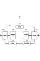
図1に示すように、本実施形態に係る車両用空気調和装置400は、鉄道車両に画定された客室を空調する空調機器100と、空調機器100の制御に必要な各種物理量を検出するセンサ群200と、センサ群200の検出結果に基づいて空調機器100を制御する空調制御装置300とを備える。以下、まず空調機器100の構成を具体的に説明する。
[Embodiment 1]
As shown in FIG. 1, the
図2に示すように、空調機器100は、冷媒を気化させる蒸発器110と、気化された冷媒を液体の冷媒から分離する気液分離器120と、分離された気体の冷媒を圧縮する圧縮機130と、圧縮された冷媒を凝縮させる凝縮器140と、凝縮された冷媒を膨張させる膨張器150とを有する。また、空調機器100は、蒸発器110、気液分離器120、圧縮機130、凝縮器140、及び膨張器150の間で冷媒を流通させる冷媒配管160も有する。
As shown in FIG. 2, the
圧縮機130は、自己の内部に画定される圧縮室に冷媒を吸い込み、吸い込んだ冷媒を圧縮室で圧縮し、圧縮された冷媒を吐出する動作を繰り返すことにより、冷媒配管160を通じて冷媒を循環させる。これにより、蒸発器110が冷却され、凝縮器140が発熱した状態となる。
The
本実施形態では、空調機器100が鉄道車両の客室を冷房する場合について述べる。この場合、蒸発器110は、客室の空気と熱交換することにより、客室を冷房する室内熱交換器としての役割を果たす。一方、凝縮器140は、客室の外部の空気と熱交換することにより、廃熱を外部に放出する室外熱交換器としての役割を果たす。
In this embodiment, a case where the
圧縮機130は、冷媒配管160を流れる単位時間当たりの冷媒の循環量を可変に調整することができる構成を有する。具体的には、圧縮機130は、上述した圧縮室の容量を弁によって機械的に2段階に切り替えることができる容量可変構造を有する。
The
圧縮機130を、圧縮室の容量が相対的に小さい状態に切り替えたとき、単位時間当たりの冷媒の循環量が低下するため、空調機器100の客室を空調する能力(以下、空調能力という。)が抑えられる。一方、圧縮機130を、圧縮室の容量が相対的に大きい状態に切り替えると、単位時間当たりの冷媒の循環量が増大するため、空調機器100の空調能力が向上する。
When the
また、空調機器100は、蒸発器110と空気との熱交換を促進する蒸発器用ファン170と、凝縮器140と空気との熱交換を促進する凝縮器用ファン180とを有する。蒸発器用ファン170は、蒸発器110と熱交換して冷却された空気を、客室に送り込む。凝縮器用ファン180は、凝縮器140と熱交換して加熱された空気を鉄道車両の外部に排出させる。
Further, the
蒸発器用ファン170と凝縮器用ファン180の各々の回転数は、可変に調整することができる。蒸発器用ファン170と凝縮器用ファン180の回転数が高い程、蒸発器110と凝縮器140における熱交換が促進されるため、空調機器100の空調能力が向上する。一方、蒸発器用ファン170と凝縮器用ファン180の回転数を低下させると、空調機器100の空調能力が抑えられる。
The rotation speeds of the
以上のように、空調機器100は、鉄道車両の客室を空調する空調能力を、圧縮機130の容量、蒸発器用ファン170の回転数、及び凝縮器用ファン180の回転数によって可変に調整することができる構成を有する。
As described above, the air-
図1に戻って説明を続ける。空調制御装置300が、圧縮機130の容量、蒸発器用ファン170の回転数、及び凝縮器用ファン180の回転数を制御することにより、空調機器100の空調能力を調整する空調能力制御を行う。
The explanation will be continued by returning to FIG. The air
空調制御装置300は、空調能力制御の動作を規定した制御プログラム310が格納されたメモリ320と、メモリ320から制御プログラム310を読み出して実行するプロセッサ330とを有する。
The air
プロセッサ330が、制御プログラム310を実行することにより、上述した空調能力制御が実現される。プロセッサ330は、空調能力制御において、空調機器100の空調能力を、センサ群200の検出結果に基づいて決定する。
The above-mentioned air conditioning capacity control is realized by the
センサ群200は、鉄道車両の客室内の温度を計測する室内温度センサ210と、鉄道車両の外部の温度を計測する室外温度センサ220と、客室の空調されにくさを表す室内熱負荷に依存する物理量を検出する室内熱負荷測定用センサ230とを含む。
The
プロセッサ330は、室内温度センサ210によって計測された客室の温度と、予め定められた目標温度との差である室温偏差を算出する。また、プロセッサ330は、室内温度センサ210及び室外温度センサ220の検出結果と、室内熱負荷測定用センサ230の検出結果とを用いて、室内熱負荷を算出する。
The
そして、プロセッサ330は、室温偏差及び室内熱負荷の値の組み合わせと、空調機器100の空調能力とを予め対応付けた空調能力判別線図を用いて、空調機器100の空調能力を決定する。以下、具体的に説明する。
Then, the
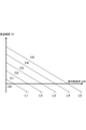
図3に示すように、空調能力判定線図は、横軸に室内熱負荷をとり、縦軸に室温偏差をとったグラフである。このグラフには、互いに平行で各々負の傾きを有する5本の直線状の境界線L1~L5が示されている。境界線L1~L5は、少なくとも第1象限を通っている。境界線L1~L5の順番に、原点からの距離が次第に大きくなっている。 As shown in FIG. 3, the air-conditioning capacity determination diagram is a graph in which the horizontal axis is the indoor heat load and the vertical axis is the room temperature deviation. This graph shows five linear boundaries L1 to L5 that are parallel to each other and each have a negative slope. The boundaries L1 to L5 pass through at least the first quadrant. The distance from the origin gradually increases in the order of the boundary lines L1 to L5.
プロセッサ330は、室内熱負荷と室温偏差のプロットが、境界線L1より下方の領域C0に属するとき、最も低い空調能力で空調機器100を運転させ、境界線L2とL1の間の領域C1に属するとき、次に高い空調能力で空調機器100を運転させ、境界線L3とL2の間の領域C2に属するとき、次に高い空調能力で空調機器100を運転させ、境界線L4とL3の間の領域C3に属するとき、次に高い空調能力で空調機器100を運転させ、境界線L5とL4の間の領域C4に属するとき、次に高い空調能力で空調機器100を運転させ、境界線L5より原点から遠い領域C5に属するとき、最も高い空調能力で空調機器100を運転させる。
The
従来は、室内熱負荷を、鉄道車両の重さから把握される乗客の総人数に基づいて算出していた。しかし、乗客の総人数の観測だけでは、客室に対する乗客の入れ替わりを適切に把握することができない。このため、たとえ客室に多くの乗客が新たに乗り込んでも、その客室における乗客の総人数の変動が小さい場合には、空調機器100の能力が高められず、客室の快適性が一時的に低下する懸念があった。
In the past, the indoor heat load was calculated based on the total number of passengers ascertained from the weight of the railroad vehicle. However, it is not possible to properly grasp the change of passengers to the cabin only by observing the total number of passengers. Therefore, even if a large number of passengers newly board the cabin, if the fluctuation in the total number of passengers in the cabin is small, the capacity of the
そこで、本実施形態では、図1に示す室内熱負荷測定用センサ230が、客室に対する乗客の入れ替わりも検知できる構成を備える。以下、室内熱負荷測定用センサ230の構成を具体的に説明する。
Therefore, in the present embodiment, the indoor heat
室内熱負荷測定用センサ230は、図5に示すように、乗客の総人数を把握するために鉄道車両の重さを検出する車重センサ231のみならず、客室に新たに搭乗した乗客の人数を把握するために、予め定められた箇所の乗客の通過を検知する乗客通過センサ232も有する。
As shown in FIG. 5, the indoor heat
図4に示すように、乗客通過センサ232は、鉄道車両TRの客室RM内に配置されている。具体的には、乗客通過センサ232は、鉄道車両TRが駅PFに到着して鉄道車両TRにおける乗降用の扉DRが開いた際に、その開かれた扉DRを乗客が通過したことを検知できる箇所に配置されている。
As shown in FIG. 4, the
より具体的には、乗客通過センサ232は、扉DRの上方に位置する車内表示装置TVの近傍に配置されている。なお、車内表示装置TVは、例えば、路線図、乗換案内、気象情報、広告等を乗客に対して視覚的に案内するものである。
More specifically, the
車内表示装置TVの近傍に乗客通過センサ232を配置する場合、乗客通過センサ232に作動電力を供給するための配線として、車内表示装置TV用に予備的に準備されている配線を流用できる。このため、乗客通過センサ232の導入に当たって、新たに配線を準備する必要がない。
When the
乗客通過センサ232は、各々乗客の通過を検知できる第1センサ部232aと第2センサ部232bを含む。第1センサ部232aと第2センサ部232bは、乗客が通過する方向、具体的に鉄道車両TRの幅方向に間隔をあけて並んでいる。
The
図示しないが、第1センサ部232aと第2センサ部232bの各々は、鉄道車両TRの進行方向、即ち図4の紙面に垂直な方向に向かい合うビーム出射器とビーム受信器とを備える。ビーム出射器は、ビーム受信器に向けて、赤外線その他の波長を有する電磁波又は音波のビームを出射している。乗客が扉DRを通過する際、ビームが乗客で遮られる。このため、ビーム受信器でのビームの受信の有無によって、乗客の通過を検知できる。
Although not shown, each of the
乗客通過センサ232は、第1センサ部232aと第2センサ部232bとでの通過の検出の順序によって、客室RMに入る向きの通過と、客室RMから出る向きの通過とを区別して検知することができる。即ち、第1センサ部232a→第2センサ部232bの順序で通過を検知した場合は、乗客が客室RMから出たことを表しており、第2センサ部232b→第1センサ部232aの順序で通過を検知した場合は、乗客が客室RMに入ったことを表している。
The
本実施形態では、乗客通過センサ232は、第2センサ部232b→第1センサ部232aの順序で通過を検知する度、即ち、新たに乗客が客室RMに入ったことを検知する度に、その旨を表す入室検知信号を、図1に示すプロセッサ330に出力する。図1に示すプロセッサ330は、入室検知信号の受信回数を加味して、図3の横軸の室内熱負荷の値を算出する。
In the present embodiment, the
以下、図5を参照し、図1に示すプロセッサ330が制御プログラム310を実行することにより発揮する機能について、具体的に説明する。
Hereinafter, the functions exhibited by the
図5に示すように、プロセッサ330は、乗客通過センサ232から上述した入室検知信号INが出力される度に、その出力の回数を表す計数値をカウントアップする計数部331としての機能を有する。計数部331での計数値を、駅PFで新たに客室RMに入った乗客の人数である新規搭乗人数の推定値とする。
As shown in FIG. 5, the
計数部331と乗客通過センサ232とによって、予め定められた箇所としての鉄道車両TRの扉DRが開閉する箇所における乗客の通過を検知することにより、鉄道車両TRの外部から客室RMに入った乗客の人数を推定する入室者数推定手段としての入室者数推定部410が構成されている。
Passengers entering the passenger compartment RM from outside the railway vehicle TR by detecting the passage of passengers at the location where the door DR of the railway vehicle TR opens and closes as a predetermined location by the
また、プロセッサ330は、客室RMに収容されている乗客の総人数を推定する総人数推定手段としての総人数推定部420を、車重センサ231と共に構成する総人数算出部332としての機能も有する。
Further, the
総人数算出部332は、車重センサ231の検出結果に基づいて、客室RMに収容されている乗客の総人数を算出する。
The total number of
具体的には、総人数算出部332は、車重センサ231の検出結果が表す鉄道車両TRとそれに搭乗している乗客との合計の重さから、鉄道車両TRだけの重さを引いた値を、1人の乗客の平均体重で割り算する。その割り算の結果の値が、客室RM内の乗客の総人数の推定値である。
Specifically, the total
また、プロセッサ330は、計数部331での計数値が表す新規搭乗人数の推定値と、総人数算出部332で算出された総人数の推定値と、室内温度センサ210及び室外温度センサ220の検出結果とを用いて、客室RMの空調されにくさを表す室内熱負荷を算出する室内熱負荷算出部333としての機能も有する。
Further, the
具体的には、室内熱負荷算出部333は、次式(1)によって室内熱負荷を算出する。
室内熱負荷[W]=乗客発熱量[W]+環境負荷[W] …(1)
Specifically, the indoor heat
Indoor heat load [W] = passenger heat generation [W] + environmental load [W] ... (1)
ここで、環境負荷とは、鉄道車両TRに備えられた各種機器の定常発熱量と、鉄道車両TRの外部から客室RMへ侵入する侵入熱量との和である。このうち、定常発熱量は、鉄道車両TRに備えられた各種機器の構成から予め定まる。また、侵入熱量は、客室RMと外部との温度差、即ち、室内温度センサ210の検出結果と室外温度センサ220の検出結果との差に比例し、その比例定数は、鉄道車両TRの構造から予め定まる。
Here, the environmental load is the sum of the steady heat generation amount of various devices provided in the railway vehicle TR and the intrusion heat amount that invades the passenger compartment RM from the outside of the railway vehicle TR. Of these, the steady calorific value is determined in advance from the configuration of various devices provided in the railway vehicle TR. Further, the amount of heat entering is proportional to the temperature difference between the cabin RM and the outside, that is, the difference between the detection result of the
また、乗客発熱量とは、客室RM内の乗客が発する熱量である。本実施形態の特徴の1つは、乗客発熱量の算出式を、鉄道車両TRが駅PFから発車した直後の過渡期間と、それ以外の定常時とで、場合分けする点にある。以下、具体的に説明する。 The passenger calorific value is the amount of heat generated by the passengers in the passenger cabin RM. One of the features of this embodiment is that the calculation formula of the passenger calorific value is divided into cases according to the transient period immediately after the railway vehicle TR departs from the station PF and the other normal time. Hereinafter, a specific description will be given.
室内熱負荷算出部333は、鉄道車両TRが駅PFから発車した直後の過渡期間以外の定常時においては、次式(2)によって、乗客発熱量を算出する。
乗客発熱量[W]=室内総人数×乗客1人当たりの定常発熱量[W] …(2)
The indoor heat
Passenger calorific value [W] = Total number of people in the room x Steady calorific value per passenger [W] ... (2)
ここで、室内総人数とは、総人数算出部332で算出された総人数の推定値のことである。また、乗客1人当たりの定常発熱量は、本実施形態では、60[W]とする。
Here, the total number of people in the room is an estimated value of the total number of people calculated by the total number of
一方、室内熱負荷算出部333は、鉄道車両TRが駅PFから発車した直後の過渡期間においては、次式(3)によって、乗客発熱量を算出する。
乗客発熱量[W]=元々客室に居た乗客の発熱量[W]+新たに客室に搭乗した乗客の発熱量[W] …(3)
On the other hand, the indoor heat
Passenger calorific value [W] = Passenger calorific value originally in the cabin [W] + Passenger calorific value newly boarded in the cabin [W] ... (3)
ここで、元々居た乗客とは、鉄道車両TRが駅PFに到着する前から客室RMに居た乗客のことである。元々居た乗客の発熱量は、上式(2)における乗客1人当たりの定常発熱量を用いて、次式(4)によって算出される。
元々客室に居た乗客の発熱量[W]=元々居た乗客の人数×乗客1人当たりの定常発熱量[W] …(4)
Here, the passengers who were originally present are the passengers who were in the passenger cabin RM before the railroad vehicle TR arrived at the station PF. The calorific value of the passengers who originally existed is calculated by the following equation (4) using the steady calorific value per passenger in the above equation (2).
The calorific value of the passengers who were originally in the cabin [W] = the number of passengers who were originally present x the steady calorific value per passenger [W] ... (4)
また、新たに搭乗した乗客とは、鉄道車両TRが駅PFに到着した際に、その駅PFで客室RMに搭乗した乗客のことである。新たに搭乗した乗客の発熱量は、上式(2)における乗客1人当たりの定常発熱量を用いて、次式(5)によって算出される。
新たに搭乗した乗客の発熱量[W]=新たに搭乗した乗客の人数×(乗客1人当たりの定常発熱量+α)[W] …(5)
The newly boarded passenger is a passenger who boarded the passenger compartment RM at the station PF when the railway vehicle TR arrived at the station PF. The calorific value of the newly boarded passenger is calculated by the following equation (5) using the steady calorific value per passenger in the above equation (2).
Calorific value of newly boarded passengers [W] = Number of newly boarded passengers x (Constant calorific value per passenger + α) [W] ... (5)
ここで、αは、新たに搭乗した乗客1人当たりの平均発熱量から、元々居た乗客1人当たりの平均発熱量を引いた値に相当する補正値である。この補正値αは、定数としてもよいし、客室RMの外部の温度、客室RMと外部との温度差、又は外部の日射量等に基づいて適宜定められる変数としてもよい。 Here, α is a correction value corresponding to a value obtained by subtracting the average calorific value per passenger who was originally present from the average calorific value per newly boarded passenger. This correction value α may be a constant, or may be a variable appropriately determined based on the temperature outside the guest room RM, the temperature difference between the guest room RM and the outside, the amount of external solar radiation, and the like.
なお、室内熱負荷算出部333は、上式(5)における新たに搭乗した乗客の人数(以下、新規搭乗人数という。)を、計数部331での計数値によって特定する。また、室内熱負荷算出部333は、式(4)における元々居た乗客の人数(以下、残留人数という。)を、鉄道車両TRが駅PFから発車する時点における総人数算出部332で算出された総人数から、新規搭乗人数を引き算することによって求める。
The indoor heat
また、プロセッサ330は、鉄道車両TRから、乗降用の扉DRが開閉したことを表す扉開閉情報を取得する扉開閉情報取得部334としての機能も有する。扉開閉情報取得部334は、扉開閉情報によって扉DRが開いたことを検知したとき、及び扉DRが閉まったことを検知したときは、その旨を室内熱負荷算出部333に通知する。
Further, the
扉開閉情報取得部334から室内熱負荷算出部333に扉DRが閉まった旨が通知された時点から、予め定められた期間、具体的には5分間経過するまでの期間を、上述した過渡期間とする。
The above-mentioned transition period is the period from the time when the door opening / closing
また、室内熱負荷算出部333は、扉開閉情報取得部334から扉DRが開いた旨を通知される度に、計数部331における計数値をリセットする。これにより、扉DRが開いた時点から、扉DRが閉まる時点までの間に、計数部331において新規搭乗人数を適切に計数することができる。
Further, the indoor heat
また、プロセッサ330は、室内温度センサ210によって計測された客室の温度と、予め定められた目標温度との差である室温偏差を算出する室温偏差算出部335としての機能も有する。
Further, the
また、プロセッサ330は、室温偏差算出部335によって算出された室温偏差と、室内熱負荷算出部333によって算出された室内熱負荷とに基づいて、図3を参照して説明した要領で空調機器100の空調能力を決定し、決定した空調能力が発揮されるように、圧縮機130、蒸発器用ファン170、及び凝縮器用ファン180を制御する空調能力制御部336としての機能も有する。
Further, the
以上説明した室内熱負荷算出部333、扉開閉情報取得部334、室温偏差算出部335、及び空調能力制御部336によって、空調機器100の空調能力を制御する制御手段としての制御部430が構成されている。
The indoor heat
制御部430は、鉄道車両TRが駅PFに到着した場合に、その駅PFで新たに客室RMに入った乗客の人数である新規搭乗人数を入室者数推定部410の推定結果によって特定すると共に、元々客室RMに居た乗客の人数である残留人数を入室者数推定部410及び総人数推定部420の推定結果を用いて特定し、空調機器100の空調能力を、新規搭乗人数、残留人数、及び室温偏差に応じて制御する。
When the railway vehicle TR arrives at the station PF, the
以下、図6及び図7を参照し、プロセッサ330が構成する上記各部331~336によって実行される空調能力制御について、具体的に説明する。
Hereinafter, the air conditioning capacity control executed by the above-mentioned
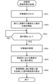
図6に示すように、まず、室温偏差算出部335は、室内温度センサ210の測定結果が表す客室RM内の温度と、予め定められた目標温度との差である室温偏差を算出する(ステップS1)。
As shown in FIG. 6, first, the room temperature
次に、室内熱負荷算出部333は、扉開閉情報取得部334から扉DRが開いた旨の通知があったか否か、即ち、鉄道車両TRが駅PFに到着して乗客の乗降のために扉DRが開いたか否かを判定する(ステップS2)。
Next, the indoor heat
室内熱負荷算出部333は、扉DRが開かれていない場合は(ステップS2;NO)、定常時熱負荷算出処理を行う(ステップS3)。定常時熱負荷算出処理とは、上述した式(1)と式(2)を用いて、室内熱負荷を算出する処理のことである。
When the door DR is not opened (step S2; NO), the indoor heat
次に、空調能力制御部336は、室温偏差算出部335によって算出された室温偏差と、室内熱負荷算出部333によって算出された室内熱負荷とに基づいて、図3を参照して説明した要領で、空調機器100の空調能力を決定する(ステップS4)。
Next, the air conditioning
次に、空調能力制御部336は、空調機器100の現在の空調能力が適切か否か、即ち、空調機器100の現在の空調能力がステップS4で決定した空調能力に等しいか否かを判定し(ステップS5)、等しい場合は(ステップS5;YES)、ステップS1に戻る。
Next, the air-conditioning
一方、空調能力制御部336は、空調機器100の現在の空調能力が、ステップS4で決定した空調能力と異なる場合は(ステップS5;NO)、ステップS4で決定した空調能力が発揮されるように、圧縮機130、蒸発器用ファン170、及び凝縮器用ファン180の少なくとも1つを制御し、予め定められた期間、具体的には、5分間、ステップS4で決定した空調能力で空調機器100を運転させる(ステップS6)。
On the other hand, when the current air-conditioning capacity of the air-
次に、空調能力制御部336は、空調能力制御を継続する場合は(ステップS7;NO)、ステップS1に戻り、空調能力制御を終える場合は(ステップS7;YES)、本処理を終了する。
Next, the air-conditioning
一方、室内熱負荷算出部333は、ステップS2で、扉DRが開かれた場合は(ステップS2;YES)、到着時熱負荷算出処理を行う(ステップS8)。到着時熱負荷算出処理とは、上述した式(1)と式(3)~(5)を用いて、室内熱負荷を算出する処理のことである。以下、図7を参照し、到着時熱負荷算出処理を具体的に説明する。
On the other hand, if the door DR is opened (step S2; YES) in step S2, the indoor heat
図7に示すように、まず、室内熱負荷算出部333は、今回到着した駅PFでの新規搭乗人数を計数させるために、計数部331における計数値をリセットし(ステップS81)、計数部331に、新たに搭乗する乗客の人数の計数を開始させる(ステップS82)。
As shown in FIG. 7, first, the indoor heat
次に、室内熱負荷算出部333は、扉開閉情報取得部334から扉DRが閉まった旨の通知があった場合、即ち、鉄道車両TRが駅PFから発車するために扉DRが閉まった場合(ステップS83;YES)、その時点の計数値を計数部331から取得する(ステップS84)。この計数値によって、その駅PFでの新規搭乗人数が特定される。
Next, when the indoor heat
次に、総人数算出部332は、扉DRが閉まった後における車重センサ231の検出結果を用いて、客室RMに収容されている乗客の総人数を算出する(ステップS85)。
Next, the total number of
次に、室内熱負荷算出部333は、ステップS85で総人数算出部332によって算出された総人数から、ステップS84で取得した計数値が表す新規搭乗人数を引き算することにより、元々客室に居た乗客の人数、即ち残留人数を算出する。
Next, the indoor heat
そして、室内熱負荷算出部333は、算出した残留人数と、ステップS84で特定した新規搭乗人数とを加味した室内熱負荷を算出する(ステップS86)。
Then, the indoor heat
具体的には、室内熱負荷算出部333は、残留人数を上式(4)に代入して、元々客室に居た乗客の発熱量を算出すると共に、新規搭乗人数を上式(5)に代入して、新たに搭乗した乗客の発熱量を算出し、上式(3)によって室内熱負荷を算出する。そして、室内熱負荷算出部333は、到着時熱負荷算出処理を終える。
Specifically, the indoor heat
以上説明したように、本実施形態によれば、鉄道車両TRが駅PFに到着した後、発車するために扉DRが閉まった際に、その駅PFで客室RMに新たに搭乗した乗客の人数である新規搭乗人数に応じて、空調機器100の空調能力が制御される。このため、駅PFで乗客の入れ替わりが生じた場合でも、客室RMの快適性が低下しにくい。
As described above, according to the present embodiment, the number of passengers newly boarded in the passenger cabin RM at the station PF when the door DR is closed to depart after the railway vehicle TR arrives at the station PF. The air conditioning capacity of the
従来は、客室RMにおける乗客の総人数は検知するが、乗客の入れ替わりは検知しなかった。このため、たとえ客室RMに多くの乗客が新たに乗り込んでも、客室RMにおける乗客の総人数の変動が小さい場合には、室温偏差が大きくなった後でないと、空調機器100の空調能力が高められないという懸念があった。
Conventionally, the total number of passengers in the passenger cabin RM is detected, but the replacement of passengers is not detected. Therefore, even if a large number of passengers newly board the cabin RM, if the fluctuation in the total number of passengers in the cabin RM is small, the air conditioning capacity of the
これに対し、本実施形態によれば、新規搭乗人数に応じて空調機器100の空調能力が制御されるので、客室RMに乗客が新たに乗り込んだ場合には、客室RMにおける乗客の総人数の変動が小さくても、客室RMの快適性が低下し始める前に、空調機器100の空調能力が高められうる。このため、客室RMの快適性が低下しにくい。
On the other hand, according to the present embodiment, the air-conditioning capacity of the air-
[実施形態2]
上記実施形態1では、空調機器100が客室RMを冷房したが、空調機器100が客室RMを暖房する場合にも、新規搭乗人数が多い程、客室RMが暖房されにくいという問題が生じる。そこで、空調制御装置300は、空調機器100が客室RMを暖房する場合にも、新規搭乗人数に応じて、空調機器100の能力を制御する。以下、その具体例について説明する。
[Embodiment 2]
In the first embodiment, the air-
本実施形態では、図2において、凝縮器140が、客室RM内の空気と熱交換することにより客室RMを暖房する室内熱交換器としての役割を果たし、蒸発器110が、鉄道車両TRの外部から熱を吸収する室外熱交換器としての役割を果たす。
In the present embodiment, in FIG. 2, the
空調機器100が客室RMを暖房する能力は、実施形態1の場合と同様に、圧縮機130の容量、蒸発器用ファン170の回転数、及び凝縮器用ファン180の回転数によって可変に調整することができる。
The ability of the
客室RMの暖房を行う冬季や寒冷地では、上式(1)の左辺に示す室内熱負荷は、目標温度への温まりにくさを表すため、負の値をとりうる。特に、式(1)の右辺の環境負荷には、客室RMから外部へ流出する流失熱量が加味される。流出熱量は、負の値をとる。その絶対値は、客室RMと外部との温度差、即ち、室内温度センサ210の検出結果と室外温度センサ220の検出結果との差に比例し、その比例定数は、鉄道車両TRの構造から予め定まる。
In winter or cold regions where the guest room RM is heated, the indoor heat load shown on the left side of the above equation (1) can take a negative value because it indicates the difficulty of warming up to the target temperature. In particular, the amount of heat loss flowing out from the guest room RM is added to the environmental load on the right side of the equation (1). The amount of outflow heat takes a negative value. The absolute value is proportional to the temperature difference between the cabin RM and the outside, that is, the difference between the detection result of the
また、本実施形態では、室内熱負荷算出部333は、図6のステップS8の到着時熱負荷算出処理における、図7のステップS86では、新規搭乗人数が多い程、室内熱負荷が小さくなるような、即ち、負の値である室内熱負荷の絶対値が大きくなるような室内熱負荷の定義式を用いて、室内熱負荷を算出する。これは、新たに搭乗する乗客は、客室RMの温度を低下させる吸熱要因となるためである。
Further, in the present embodiment, the indoor heat
なお、新たに客室RMに搭乗する乗客1人当たりの吸熱量は、定数としてもよいし、客室RMの外部の温度、客室RMと外部との温度差、又は外部の日射量等に基づいて適宜定められる変数としてもよい。 The amount of heat absorbed per passenger newly boarding the cabin RM may be a constant, and may be appropriately determined based on the temperature outside the cabin RM, the temperature difference between the cabin RM and the outside, the amount of external solar radiation, and the like. It may be a variable to be used.
一方、本実施形態では、室内熱負荷算出部333は、図6のステップS3の定常時熱負荷算出処理では、客室RM内の乗客の総人数が多い程、室内熱負荷が大きくなるような、即ち、負の値である室内熱負荷の絶対値が小さくなるような室内熱負荷の定義式を用いて、室内熱負荷を算出する。これは、定常時には、客室RM内の総人数が多い程、客室RMが温まりやすいためである。
On the other hand, in the present embodiment, in the steady-state heat load calculation process of step S3 of FIG. 6, the indoor heat
以上のように、上式(1)の左辺に示す室内熱負荷は、負の値をとりうる。また、客室RMの暖房を行う場合は、客室RMの温度-目標温度、で定義される室温偏差も、負の値をとりうる。 As described above, the indoor heat load shown on the left side of the above equation (1) can take a negative value. Further, when heating the guest room RM, the room temperature deviation defined by the temperature of the guest room RM-the target temperature can also take a negative value.
そこで、空調能力制御部336は、図6のステップS4では、図8に示す、暖房時用の空調能力判定線図を用いて、空調機器100の空調能力、即ち暖房能力を決定する。
Therefore, in step S4 of FIG. 6, the air-conditioning
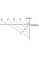
図8に示すように、暖房時に使用する空調能力判定線図も、横軸に室内熱負荷をとり、縦軸に室温偏差をとったグラフである。このグラフには、互いに平行で各々負の傾きを有する4本の直線状の境界線M1~M4が示されている。境界線M1~M4は、少なくとも第3象限を通っている。境界線M1~M4の順番に、原点からの距離が次第に大きくなっている。 As shown in FIG. 8, the air-conditioning capacity determination diagram used during heating is also a graph in which the horizontal axis is the indoor heat load and the vertical axis is the room temperature deviation. This graph shows four linear boundaries M1 to M4 that are parallel to each other and each have a negative slope. The boundaries M1 to M4 pass through at least the third quadrant. The distance from the origin gradually increases in the order of the boundary lines M1 to M4.
空調能力制御部336は、室内熱負荷と室温偏差のプロットが、境界線M1より上方の領域H0に属するとき、最も低い暖房能力で空調機器100を運転させ、境界線M2とM1の間の領域H1に属するとき、次に高い空調能力で空調機器100を運転させ、境界線M3とM2の間の領域H2に属するとき、次に高い空調能力で空調機器100を運転させ、境界線M4とM3の間の領域H3に属するとき、次に高い空調能力で空調機器100を運転させ、境界線M4より原点から遠い領域H4に属するとき、最も高い空調能力で空調機器100を運転させる。
When the plot of the indoor heat load and the room temperature deviation belongs to the region H0 above the boundary line M1, the air conditioning
本実施形態によれば、新規搭乗人数に応じて、空調機器100の客室RMを暖房する能力が制御される。このため、乗客の入れ替わりが生じた場合でも、客室RMの温度が一時的に低下する前に、空調機器100の客室RMを暖房する能力が高められる。
According to the present embodiment, the ability to heat the cabin RM of the
[実施形態3]
上記実施形態では、図4に示したように、乗客通過センサ232を、鉄道車両TRの客室RM内に配置したが、乗客通過センサ232を配置する位置は、特に限定されない。以下、乗客通過センサ232の配置位置を変更した具体例について述べる。
[Embodiment 3]
In the above embodiment, as shown in FIG. 4, the
図9に示すように、本実施形態では、乗客通過センサ232が、駅PFのホームドアHDRに設置される。ホームドアHDRは、鉄道車両TRが駅PFに到着した場合に、鉄道車両TRに設けられた乗降用の扉DRと連動して開閉する。
As shown in FIG. 9, in the present embodiment, the
乗客通過センサ232は、鉄道車両TRが駅PFに到着して扉DR及びホームドアHDRが開いた時点から、鉄道車両TRが発車するために扉DR及びホームドアHDRが閉まった時点までの間に、開かれたホームドアHDRを、乗客が客室RMに入る向きに通過する度に、入室検知信号INを、図5に示す計数部331に出力する。
The
なお、本実施形態では、ホームドアHDRに設置される乗客通過センサ232は、入室検知信号INを、無線の形態、具体的には電磁波又は音波のパルスの形態で、図5に示す計数部331に出力する。
In the present embodiment, the
図5に示す計数部331は、乗客通過センサ232から入室検知信号INが出力される度に計数値をカウントアップすることにより、開かれたホームドアHDRを通過する乗客の人数を計数する。これにより、その駅PFにおける新規搭乗人数を計数できる。本実施形態によっても、実施形態1と同様の効果が得られる。
The
[実施形態4]
上記実施形態では、客室RMにおける乗客の総人数を、鉄道車両TRの重量に基づいて推定したが、客室RMにおける乗客の総人数は、鉄道車両TRの重量によらずに推定することもできる。以下、その具体例について述べる。
[Embodiment 4]
In the above embodiment, the total number of passengers in the passenger compartment RM is estimated based on the weight of the railroad vehicle TR, but the total number of passengers in the passenger compartment RM can also be estimated regardless of the weight of the railroad vehicle TR. Hereinafter, specific examples thereof will be described.
図10に示すように、本実施形態に係る乗客通過センサ233は、客室RMに入る向きの乗客の通過と、客室RMから出る向きの乗客の通過との双方を区別して検知し、客室RMに入る向きの乗客の通過を検知する度に入室検知信号INを出力し、客室RMから出る向きの乗客の通過を検知する度に退室検知信号OUTを出力する。
As shown in FIG. 10, the
図11に示すように、乗客通過センサ233は、客室RM内における扉DRの位置のみならず、取り合う鉄道車両TRの客室RM同士を連通させる連絡通路CNの位置にも配置されている。連絡通路CNに配置された乗客通過センサ233は、連絡通路CNにおける乗客の通過を検知する。
As shown in FIG. 11, the
これらの乗客通過センサ233の各々が、上述した入室検知信号IN及び退室検知信号OUTを出力する。なお、図10には、理解を容易にするために、代表して1つの乗客通過センサ233のみを示した。
Each of these
図10に戻って説明を続ける。本実施形態では、図1に示したプロセッサ330が、いずれかの乗客通過センサ233から入室検知信号INが出力される度に、その出力の回数を表す計数値をカウントアップする第1計数部337としての機能と、いずれかの乗客通過センサ233から退室検知信号OUTが出力される度に、その出力の回数を表す計数値をカウントアップする第2計数部338としての機能とを有する。
The explanation will be continued by returning to FIG. In the present embodiment, the
室内熱負荷算出部333は、鉄道車両TRが駅PFに到着して扉DRが開く度に、即ち扉開閉情報取得部334から扉DRが開いた旨を通知される度に、第1計数部337及び第2計数部338の計数値をリセットする。
The indoor heat
また、室内熱負荷算出部333は、鉄道車両TRが発車すべく扉DRが閉まる度に、即ち扉開閉情報取得部334から扉DRが閉まった旨を通知される度に、第1計数部337の計数結果-第2計数部338の計数結果、で定義される変動人数を算出する。
Further, the indoor heat
そして、室内熱負荷算出部333は、算出した変動人数を、前回の総人数、即ち前の駅PFで扉DRが閉まった時点における客室RM内の乗客の総人数に足し算する。この足し算の結果が、今回の駅PFで扉DRが閉まった時点における客室RM内の乗客の総人数である。
Then, the indoor heat
この総人数の値は、室内熱負荷算出部333に記憶され、次の駅PFで扉DRが閉まった時点における総人数の算出に利用される。また、この総人数の値は、実施形態1の場合と同様に、室内熱負荷の算出にも利用される。なお、鉄道車両TRが運行を開始した時点での総人数の初期値はゼロとする。
The value of the total number of people is stored in the indoor heat
このように、本実施形態では、乗客通過センサ233、第1計数部337、及び第2計数部338、及び室内熱負荷算出手段によって、客室RMに収容されている乗客の総人数を推定する総人数推定手段が構成される。
As described above, in the present embodiment, the total number of passengers accommodated in the passenger cabin RM is estimated by the
また、室内熱負荷算出部333は、第1計数部337の計数結果によって新規入室者数を特定する。即ち、第1計数部337と乗客通過センサ233によって、客室RMに入った乗客の人数を推定する入室者数推定手段が構成される点は、実施形態1と同じである。また、上記以外の室内熱負荷算出部333の機能も、実施形態1と同じである。
Further, the indoor heat
以上説明したように、本実施形態によれば、図5に示した車重センサ231を用いなくても、鉄道車両TRが駅PFに到着する度に、その駅PFでの乗客の変動人数に基づいて客室RM内の乗客の総人数を推定することができる。
As described above, according to the present embodiment, even if the
以上、本発明の実施形態について説明した。本発明はこれに限られず、以下に述べる変形も可能である。 The embodiment of the present invention has been described above. The present invention is not limited to this, and the modifications described below are also possible.
上記実施形態1では、図5に示す乗客通過センサ232が、客室RMに入る向きの乗客の通過を検知する度に入室検知信号INを出力したが、乗客通過センサ232が、客室RMから出る向きの乗客の通過を検知する度に退室検知信号OUTを出力してもよい。この場合、図5に示す計数部331は、客室RMに入った乗客の人数と客室RMから出た乗客の人数のうち、客室RMから出た乗客の人数のみを計数する。
In the first embodiment, the
この場合でも、計数部331の計数値から特定される、駅PFで客室RMから降車した乗客の人数をx、その駅PFから鉄道車両TRが発車すべく扉DRが閉まった時点での客室RM内の乗客の総人数をm、その駅PFに鉄道車両TRが到着して扉DRが開く時点での客室RM内の乗客の総人数をn、としたとき、新規搭乗人数yは、y=m+x-nによって算出することができる。
Even in this case, the number of passengers disembarking from the passenger compartment RM at the station PF, which is specified from the count value of the
上記実施形態1~4では、空調制御装置300が、乗客通過センサ232又は233から出力される入室検知信号IN又は退室検知信号OUTの出力回数を計数する機能を備えたが、この計数の機能は、乗客通過センサ232又は233自体が備えてもよい。その場合は、計数部331、第1計数部337、第2計数部338を省略し得る。
In the above embodiments 1 to 4, the air
上記実施形態1及び2では、図3及び図8に示した空調能力判別線図を用いて、空調機器100の空調能力を段階的に制御したが、空調機器100の空調能力を無段階的に調整できる構成としてもよい。また、上記実施形態1では、圧縮機130の容量を機械的に切り替え可能としたが、圧縮機130が単位時間当たりに吐出する冷媒の量は、圧縮機130の運転周波数によっても段階的又は無段階的に調整できる。
In the first and second embodiments, the air conditioning capacity of the
また、図2には、空調機器100が1系統の冷凍サイクルを備える構成を例示したが、空調機器100が複数系統の冷凍サイクルを備える場合には、可動させる冷凍サイクルの台数によっても、空調機器100の空調能力を調整できる。
Further, FIG. 2 illustrates a configuration in which the
上記実施形態2では、冷凍サイクルを構成する空調機器100によって、客室RMを暖房する構成について述べたが、客室RMは、冷凍サイクルによらず、電気ヒータによって暖房することもできる。その場合でも、電気ヒータへの通電量によって暖房能力を調整できる。なお、電気ヒータは、典型的には、客室RM内における座席の下部に設置される。
In the second embodiment, the configuration in which the guest room RM is heated by the
上記実施形態1~4で用いた乗客通過センサ232及び233の構成は、予め定められた箇所の乗客の通過を検知できるものであればよく、特に第1センサ部232a及び第2センサ部232bを有する形態に限られない。上記実施形態1~4では、室外温度センサ220が鉄道車両TRに設けられた構成について述べたが、室外温度センサ220は駅PFに設けられていてもよい。
The
上記実施形態では、車両が鉄道車両TRである場合について述べたが、車両は鉄道車両TRに限られない。本明細書において、車両とは、モノレールその他の軌道車両、及びバスその他の自動車も含む概念とする。また、本明細書において、駅とは、鉄道車両TRの駅のみならず、軌道車両の駅、バス停、その他、乗客が乗降するための停車場を含む概念とする。 In the above embodiment, the case where the vehicle is a railroad vehicle TR has been described, but the vehicle is not limited to the railroad vehicle TR. In the present specification, the concept of a vehicle includes a monorail and other track vehicles, and a bus and other automobiles. Further, in the present specification, the station is a concept including not only a railway vehicle TR station but also a track vehicle station, a bus stop, and other stops for passengers to get on and off.
図1に示す制御プログラム310をコンピュータにインストールすることで、そのコンピュータを空調制御装置300として機能させることもできる。制御プログラム310は、通信回線を介して配布してもよいし、光ディスク、磁気ディスク、光磁気ディスク、フラッシュメモリといったコンピュータ読み取り可能な記録媒体に格納して配布してもよい。
By installing the
100…空調機器、110…蒸発器、120…気液分離器、130…圧縮機、140…凝縮器、150…膨張器、160…冷媒配管、170…蒸発器用ファン、180…凝縮器用ファン、200…センサ群、210…室内温度センサ、220…室外温度センサ、230…室内熱負荷測定用センサ、231…車重センサ、232…乗客通過センサ、232a…第1センサ部、232b…第2センサ部、233…乗客通過センサ、300…空調制御装置、310…制御プログラム、320…メモリ、330…プロセッサ、331…計数部、332…総人数算出部、333…室内熱負荷算出部、334…扉開閉情報取得部、335…室温偏差算出部、336…空調能力制御部、337…第1計数部、338…第2計数部、400…車両用空気調和装置、410…入室者数推定部、420…総人数推定部、430…制御部、L1~L5…境界線、M1~M4…境界線、TR…鉄道車両(車両)、RM…客室、PF…駅、DR…扉、TV…車内表示装置、HDR…ホームドア、CN…連絡通路。 100 ... Air conditioning equipment, 110 ... Evaporator, 120 ... Gas-liquid separator, 130 ... Compressor, 140 ... Condenser, 150 ... Inflator, 160 ... Refrigerator piping, 170 ... Evaporator fan, 180 ... Condenser fan, 200 ... Sensor group, 210 ... Indoor temperature sensor, 220 ... Outdoor temperature sensor, 230 ... Indoor heat load measurement sensor, 231 ... Vehicle weight sensor, 232 ... Passenger passage sensor, 232a ... First sensor unit, 232b ... Second sensor unit , 233 ... Passenger passage sensor, 300 ... Air conditioning control device, 310 ... Control program, 320 ... Memory, 330 ... Processor, 331 ... Counting unit, 332 ... Total number of people calculation unit, 333 ... Indoor heat load calculation unit, 334 ... Door opening / closing Information acquisition unit, 335 ... Room temperature deviation calculation unit, 336 ... Air conditioning capacity control unit, 337 ... First counting unit, 338 ... Second counting unit, 400 ... Vehicle air conditioner, 410 ... Number of occupants estimation unit, 420 ... Total number estimation unit, 430 ... control unit, L1 to L5 ... boundary line, M1 to M4 ... boundary line, TR ... railway vehicle (vehicle), RM ... guest room, PF ... station, DR ... door, TV ... in-vehicle display device, HDR ... home door, CN ... connecting passage.
Claims (8)
予め定められた箇所の乗客の通過を検知することにより、前記車両の外部から前記客室に入った乗客の人数を推定する入室者数推定手段と、
前記車両が駅に到着した場合に、該駅で新たに前記客室に入った乗客の人数である新規搭乗人数を前記入室者数推定手段の推定結果によって特定し、前記空調機器の前記客室を空調する能力を、前記新規搭乗人数から算出する室内熱負荷に応じて制御する制御手段と、
を備える、車両用空気調和装置。 Air conditioning equipment that air-conditions the guest rooms defined in the vehicle,
A means for estimating the number of occupants, which estimates the number of passengers who have entered the cabin from the outside of the vehicle by detecting the passage of passengers at a predetermined location.
When the vehicle arrives at the station, the number of new passengers, which is the number of passengers newly entering the cabin at the station, is specified by the estimation result of the number of occupants estimation means, and the cabin of the air conditioner is used. A control means that controls the ability to air-condition according to the indoor heat load calculated from the number of new passengers.
An air conditioner for vehicles.
前記制御手段が、前記車両が前記駅から発車する場合に、該駅に前記車両が到着する前から前記客室に居た乗客の人数である残留人数を、前記総人数推定手段の推定結果と、前記入室者数推定手段の推定結果とを用いて特定し、前記空調機器の前記能力を、前記新規搭乗人数及び前記残留人数から算出する前記室内熱負荷に応じて制御する、
請求項1に記載の車両用空気調和装置。 Further equipped with a total number estimation means for estimating the total number of passengers accommodated in the passenger cabin.
When the vehicle departs from the station, the control means determines the number of remaining passengers, which is the number of passengers in the cabin before the vehicle arrives at the station, as the estimation result of the total number estimation means. It is specified by using the estimation result of the number of occupants estimation means, and the capacity of the air conditioner is controlled according to the indoor heat load calculated from the number of new passengers and the number of remaining passengers.
The vehicle air conditioner according to claim 1.
予め定められた箇所の乗客の通過を、前記客室に入る向きの前記通過と、前記客室から出る向きの前記通過とを区別して検知することにより、前記客室に入った乗客の人数と、前記客室から出た乗客の人数との少なくとも一方を計数する通過センサ、
を有する、請求項1又は2に記載の車両用空気調和装置。 The means for estimating the number of occupants
By detecting the passage of passengers at a predetermined location by distinguishing between the passage in the direction of entering the cabin and the passage in the direction of exiting the cabin, the number of passengers entering the cabin and the passenger cabin are detected. Passenger sensor, which counts at least one of the number of passengers leaving
The vehicle air conditioner according to claim 1 or 2.
前記車両に設けられた乗降用の扉を通過する乗客の人数を計数する、
請求項3に記載の車両用空気調和装置。 The passage sensor
Counting the number of passengers passing through the doors for getting on and off the vehicle.
The vehicle air conditioner according to claim 3.
前記駅に設置され、前記車両に設けられた乗降用の扉と連動して開閉するホームドアを通過する乗客の人数を計数する、
請求項3に記載の車両用空気調和装置。 The passage sensor
Counting the number of passengers passing through platform doors installed at the station and opening and closing in conjunction with the doors for getting on and off of the vehicle.
The vehicle air conditioner according to claim 3.
請求項1から5のいずれか一項に記載の車両用空気調和装置。The vehicle air conditioner according to any one of claims 1 to 5.
請求項1から6のいずれか一項に記載の車両用空気調和装置。The vehicle air conditioner according to any one of claims 1 to 6.
新たに前記客室に入った乗客の人数である新規搭乗人数を前記入室者数推定ステップの推定結果によって特定し、前記客室を空調する空調機器の前記客室を空調する能力を、前記新規搭乗人数から算出する室内熱負荷に応じて制御する制御ステップと、
を含む、車両用空気調和方法。 A step of estimating the number of occupants, which estimates the number of passengers who have entered the cabin defined in the vehicle from the outside of the vehicle by detecting the passage of passengers at a predetermined location.
The new passenger number, which is the number of passengers newly entered in the cabin, is specified by the estimation result of the number of occupants estimation step, and the ability of the air-conditioning device for air-conditioning the cabin to air-condition the cabin is determined by the new passenger number. Control steps to control according to the indoor heat load calculated from
Air conditioning methods for vehicles, including.
Priority Applications (1)
| Application Number | Priority Date | Filing Date | Title |
|---|---|---|---|
| JP2017236622A JP7004560B2 (en) | 2017-12-11 | 2017-12-11 | Vehicle air conditioner and vehicle air conditioner |
Applications Claiming Priority (1)
| Application Number | Priority Date | Filing Date | Title |
|---|---|---|---|
| JP2017236622A JP7004560B2 (en) | 2017-12-11 | 2017-12-11 | Vehicle air conditioner and vehicle air conditioner |
Publications (2)
| Publication Number | Publication Date |
|---|---|
| JP2019104294A JP2019104294A (en) | 2019-06-27 |
| JP7004560B2 true JP7004560B2 (en) | 2022-01-21 |
Family
ID=67060876
Family Applications (1)
| Application Number | Title | Priority Date | Filing Date |
|---|---|---|---|
| JP2017236622A Active JP7004560B2 (en) | 2017-12-11 | 2017-12-11 | Vehicle air conditioner and vehicle air conditioner |
Country Status (1)
| Country | Link |
|---|---|
| JP (1) | JP7004560B2 (en) |
Families Citing this family (2)
| Publication number | Priority date | Publication date | Assignee | Title |
|---|---|---|---|---|
| CN112918209B (en) * | 2019-12-05 | 2023-05-12 | 新奥数能科技有限公司 | Intelligent temperature-regulating bus and intelligent temperature-regulating control method thereof |
| CN111516719B (en) * | 2020-05-22 | 2021-05-11 | 中车株洲电力机车有限公司 | Air conditioner control method and system for railway vehicle |
Citations (4)
| Publication number | Priority date | Publication date | Assignee | Title |
|---|---|---|---|---|
| JP2006188150A (en) | 2005-01-06 | 2006-07-20 | Nippon Signal Co Ltd:The | Prediction system for rate of occupancy |
| JP2012121483A (en) | 2010-12-09 | 2012-06-28 | Mitsubishi Electric Corp | Apparatus for detecting situation of platform |
| JP2014234110A (en) | 2013-06-04 | 2014-12-15 | 三菱電機株式会社 | Air conditioner for vehicle |
| JP2015101203A (en) | 2013-11-25 | 2015-06-04 | 三菱電機株式会社 | Air conditioning system for railway vehicle |
Family Cites Families (1)
| Publication number | Priority date | Publication date | Assignee | Title |
|---|---|---|---|---|
| JP3164942B2 (en) * | 1993-06-28 | 2001-05-14 | 松下電器産業株式会社 | Ride status guidance management system |
-
2017
- 2017-12-11 JP JP2017236622A patent/JP7004560B2/en active Active
Patent Citations (4)
| Publication number | Priority date | Publication date | Assignee | Title |
|---|---|---|---|---|
| JP2006188150A (en) | 2005-01-06 | 2006-07-20 | Nippon Signal Co Ltd:The | Prediction system for rate of occupancy |
| JP2012121483A (en) | 2010-12-09 | 2012-06-28 | Mitsubishi Electric Corp | Apparatus for detecting situation of platform |
| JP2014234110A (en) | 2013-06-04 | 2014-12-15 | 三菱電機株式会社 | Air conditioner for vehicle |
| JP2015101203A (en) | 2013-11-25 | 2015-06-04 | 三菱電機株式会社 | Air conditioning system for railway vehicle |
Also Published As
| Publication number | Publication date |
|---|---|
| JP2019104294A (en) | 2019-06-27 |
Similar Documents
| Publication | Publication Date | Title |
|---|---|---|
| US9452661B2 (en) | Vehicle air conditioning system | |
| KR900001875B1 (en) | Air-conditioner | |
| US9434235B2 (en) | Vehicle air handling system | |
| US20080315000A1 (en) | Integrated Controller And Fault Indicator For Heating And Cooling Systems | |
| US20070240437A1 (en) | Air conditioning controller | |
| EP2913602A1 (en) | Air conditioning system | |
| JP5445514B2 (en) | Air conditioner for vehicles | |
| JP7004560B2 (en) | Vehicle air conditioner and vehicle air conditioner | |
| KR101117496B1 (en) | System for controlling air-conditioning of subway coach using carbon dioxide concentration, and method for the same | |
| JP6147049B2 (en) | Railway vehicle ventilation control system | |
| JP2018103720A (en) | Air conditioner | |
| JP5361816B2 (en) | Railway vehicle air conditioning system | |
| JP2001113939A (en) | Air conditioner for vehicle | |
| CN109760704A (en) | A kind of vehicle humidity control method used for rail vehicle | |
| JP2018034705A (en) | Air conditioner for vehicle | |
| JP6168972B2 (en) | Air conditioning system for railway vehicles | |
| Mansour et al. | Development of novel control strategy for multiple circuit, roof top bus air conditioning system in hot humid countries | |
| JP2018090046A (en) | Air conditioner for vehicle | |
| JP4970916B2 (en) | Air conditioning control device for vehicles | |
| EP3640112B1 (en) | Vehicular air-conditioning apparatus and air-conditioning method of vehicular air-conditioning apparatus | |
| JP5773751B2 (en) | Air conditioner for vehicles | |
| US20200139786A1 (en) | Air-conditioning device | |
| JP6767856B2 (en) | Vehicle air conditioner | |
| JPH079995A (en) | Air conditioner for vehicle and method for controlling the same | |
| KR101977742B1 (en) | Air conditioner for vehicle and control method thereof |
Legal Events
| Date | Code | Title | Description |
|---|---|---|---|
| A621 | Written request for application examination |
Free format text: JAPANESE INTERMEDIATE CODE: A621 Effective date: 20201009 |
|
| A977 | Report on retrieval |
Free format text: JAPANESE INTERMEDIATE CODE: A971007 Effective date: 20210824 |
|
| A131 | Notification of reasons for refusal |
Free format text: JAPANESE INTERMEDIATE CODE: A131 Effective date: 20210831 |
|
| A601 | Written request for extension of time |
Free format text: JAPANESE INTERMEDIATE CODE: A601 Effective date: 20210902 |
|
| A521 | Written amendment |
Free format text: JAPANESE INTERMEDIATE CODE: A523 Effective date: 20211105 |
|
| TRDD | Decision of grant or rejection written | ||
| A01 | Written decision to grant a patent or to grant a registration (utility model) |
Free format text: JAPANESE INTERMEDIATE CODE: A01 Effective date: 20211207 |
|
| A61 | First payment of annual fees (during grant procedure) |
Free format text: JAPANESE INTERMEDIATE CODE: A61 Effective date: 20220104 |
|
| R150 | Certificate of patent or registration of utility model |
Ref document number: 7004560 Country of ref document: JP Free format text: JAPANESE INTERMEDIATE CODE: R150 |