EP4092356A1 - Absorption machine comprising spiral plate heat exchangers - Google Patents
Absorption machine comprising spiral plate heat exchangers Download PDFInfo
- Publication number
- EP4092356A1 EP4092356A1 EP22173689.5A EP22173689A EP4092356A1 EP 4092356 A1 EP4092356 A1 EP 4092356A1 EP 22173689 A EP22173689 A EP 22173689A EP 4092356 A1 EP4092356 A1 EP 4092356A1
- Authority
- EP
- European Patent Office
- Prior art keywords
- solution
- module
- exchange device
- heat exchange
- inlet
- Prior art date
- Legal status (The legal status is an assumption and is not a legal conclusion. Google has not performed a legal analysis and makes no representation as to the accuracy of the status listed.)
- Granted
Links
- 238000010521 absorption reaction Methods 0.000 title claims abstract description 49
- 238000001816 cooling Methods 0.000 claims abstract description 97
- 239000012530 fluid Substances 0.000 claims abstract description 97
- 238000009826 distribution Methods 0.000 claims abstract description 77
- 239000013529 heat transfer fluid Substances 0.000 claims description 130
- 239000003507 refrigerant Substances 0.000 claims description 109
- 239000000203 mixture Substances 0.000 claims description 83
- 239000006096 absorbing agent Substances 0.000 claims description 69
- 238000004519 manufacturing process Methods 0.000 claims description 27
- QGZKDVFQNNGYKY-UHFFFAOYSA-N Ammonia Chemical compound N QGZKDVFQNNGYKY-UHFFFAOYSA-N 0.000 claims description 10
- 238000001704 evaporation Methods 0.000 claims description 8
- IIPYXGDZVMZOAP-UHFFFAOYSA-N lithium nitrate Chemical compound [Li+].[O-][N+]([O-])=O IIPYXGDZVMZOAP-UHFFFAOYSA-N 0.000 claims description 8
- 230000008020 evaporation Effects 0.000 claims description 7
- XLYOFNOQVPJJNP-UHFFFAOYSA-N water Substances O XLYOFNOQVPJJNP-UHFFFAOYSA-N 0.000 claims description 6
- 229910021529 ammonia Inorganic materials 0.000 claims description 5
- LFQSCWFLJHTTHZ-UHFFFAOYSA-N Ethanol Chemical compound CCO LFQSCWFLJHTTHZ-UHFFFAOYSA-N 0.000 claims description 3
- VGTPCRGMBIAPIM-UHFFFAOYSA-M sodium thiocyanate Chemical compound [Na+].[S-]C#N VGTPCRGMBIAPIM-UHFFFAOYSA-M 0.000 claims description 3
- 239000002904 solvent Substances 0.000 claims description 3
- 238000011144 upstream manufacturing Methods 0.000 claims description 2
- 235000021183 entrée Nutrition 0.000 description 32
- 239000002826 coolant Substances 0.000 description 11
- 239000012071 phase Substances 0.000 description 9
- 230000008901 benefit Effects 0.000 description 6
- 230000000694 effects Effects 0.000 description 6
- 238000005191 phase separation Methods 0.000 description 5
- 238000000926 separation method Methods 0.000 description 5
- 239000007791 liquid phase Substances 0.000 description 4
- 238000011084 recovery Methods 0.000 description 4
- 238000003860 storage Methods 0.000 description 4
- 230000008859 change Effects 0.000 description 3
- 239000007792 gaseous phase Substances 0.000 description 3
- 230000006872 improvement Effects 0.000 description 3
- 230000003993 interaction Effects 0.000 description 3
- 238000012423 maintenance Methods 0.000 description 3
- VHUUQVKOLVNVRT-UHFFFAOYSA-N Ammonium hydroxide Chemical compound [NH4+].[OH-] VHUUQVKOLVNVRT-UHFFFAOYSA-N 0.000 description 2
- 238000010586 diagram Methods 0.000 description 2
- 239000011552 falling film Substances 0.000 description 2
- 239000010408 film Substances 0.000 description 2
- 230000004907 flux Effects 0.000 description 2
- 230000014509 gene expression Effects 0.000 description 2
- 238000007689 inspection Methods 0.000 description 2
- 239000007788 liquid Substances 0.000 description 2
- 229910052751 metal Inorganic materials 0.000 description 2
- 239000002184 metal Substances 0.000 description 2
- 238000000034 method Methods 0.000 description 2
- 210000000056 organ Anatomy 0.000 description 2
- WYTGDNHDOZPMIW-RCBQFDQVSA-N alstonine Natural products C1=CC2=C3C=CC=CC3=NC2=C2N1C[C@H]1[C@H](C)OC=C(C(=O)OC)[C@H]1C2 WYTGDNHDOZPMIW-RCBQFDQVSA-N 0.000 description 1
- 235000011114 ammonium hydroxide Nutrition 0.000 description 1
- 238000006243 chemical reaction Methods 0.000 description 1
- 230000001419 dependent effect Effects 0.000 description 1
- 238000003795 desorption Methods 0.000 description 1
- 238000005516 engineering process Methods 0.000 description 1
- 230000007613 environmental effect Effects 0.000 description 1
- 239000007789 gas Substances 0.000 description 1
- 238000010438 heat treatment Methods 0.000 description 1
- 238000005457 optimization Methods 0.000 description 1
- 238000011176 pooling Methods 0.000 description 1
- 230000009467 reduction Effects 0.000 description 1
- 238000005057 refrigeration Methods 0.000 description 1
- 238000005096 rolling process Methods 0.000 description 1
- 238000006467 substitution reaction Methods 0.000 description 1
- 230000009466 transformation Effects 0.000 description 1
- 230000007704 transition Effects 0.000 description 1
- 239000002699 waste material Substances 0.000 description 1
Images


Classifications
-
- F—MECHANICAL ENGINEERING; LIGHTING; HEATING; WEAPONS; BLASTING
- F25—REFRIGERATION OR COOLING; COMBINED HEATING AND REFRIGERATION SYSTEMS; HEAT PUMP SYSTEMS; MANUFACTURE OR STORAGE OF ICE; LIQUEFACTION SOLIDIFICATION OF GASES
- F25B—REFRIGERATION MACHINES, PLANTS OR SYSTEMS; COMBINED HEATING AND REFRIGERATION SYSTEMS; HEAT PUMP SYSTEMS
- F25B15/00—Sorption machines, plants or systems, operating continuously, e.g. absorption type
- F25B15/02—Sorption machines, plants or systems, operating continuously, e.g. absorption type without inert gas
- F25B15/04—Sorption machines, plants or systems, operating continuously, e.g. absorption type without inert gas the refrigerant being ammonia evaporated from aqueous solution
-
- F—MECHANICAL ENGINEERING; LIGHTING; HEATING; WEAPONS; BLASTING
- F25—REFRIGERATION OR COOLING; COMBINED HEATING AND REFRIGERATION SYSTEMS; HEAT PUMP SYSTEMS; MANUFACTURE OR STORAGE OF ICE; LIQUEFACTION SOLIDIFICATION OF GASES
- F25B—REFRIGERATION MACHINES, PLANTS OR SYSTEMS; COMBINED HEATING AND REFRIGERATION SYSTEMS; HEAT PUMP SYSTEMS
- F25B15/00—Sorption machines, plants or systems, operating continuously, e.g. absorption type
- F25B15/02—Sorption machines, plants or systems, operating continuously, e.g. absorption type without inert gas
- F25B15/06—Sorption machines, plants or systems, operating continuously, e.g. absorption type without inert gas the refrigerant being water vapour evaporated from a salt solution, e.g. lithium bromide
-
- F—MECHANICAL ENGINEERING; LIGHTING; HEATING; WEAPONS; BLASTING
- F25—REFRIGERATION OR COOLING; COMBINED HEATING AND REFRIGERATION SYSTEMS; HEAT PUMP SYSTEMS; MANUFACTURE OR STORAGE OF ICE; LIQUEFACTION SOLIDIFICATION OF GASES
- F25B—REFRIGERATION MACHINES, PLANTS OR SYSTEMS; COMBINED HEATING AND REFRIGERATION SYSTEMS; HEAT PUMP SYSTEMS
- F25B37/00—Absorbers; Adsorbers
-
- F—MECHANICAL ENGINEERING; LIGHTING; HEATING; WEAPONS; BLASTING
- F28—HEAT EXCHANGE IN GENERAL
- F28D—HEAT-EXCHANGE APPARATUS, NOT PROVIDED FOR IN ANOTHER SUBCLASS, IN WHICH THE HEAT-EXCHANGE MEDIA DO NOT COME INTO DIRECT CONTACT
- F28D9/00—Heat-exchange apparatus having stationary plate-like or laminated conduit assemblies for both heat-exchange media, the media being in contact with different sides of a conduit wall
- F28D9/04—Heat-exchange apparatus having stationary plate-like or laminated conduit assemblies for both heat-exchange media, the media being in contact with different sides of a conduit wall the conduits being formed by spirally-wound plates or laminae
-
- F—MECHANICAL ENGINEERING; LIGHTING; HEATING; WEAPONS; BLASTING
- F25—REFRIGERATION OR COOLING; COMBINED HEATING AND REFRIGERATION SYSTEMS; HEAT PUMP SYSTEMS; MANUFACTURE OR STORAGE OF ICE; LIQUEFACTION SOLIDIFICATION OF GASES
- F25B—REFRIGERATION MACHINES, PLANTS OR SYSTEMS; COMBINED HEATING AND REFRIGERATION SYSTEMS; HEAT PUMP SYSTEMS
- F25B2333/00—Details of boilers; Analysers; Rectifiers
- F25B2333/006—Details of boilers; Analysers; Rectifiers the generator or boiler having a rectifier
-
- Y—GENERAL TAGGING OF NEW TECHNOLOGICAL DEVELOPMENTS; GENERAL TAGGING OF CROSS-SECTIONAL TECHNOLOGIES SPANNING OVER SEVERAL SECTIONS OF THE IPC; TECHNICAL SUBJECTS COVERED BY FORMER USPC CROSS-REFERENCE ART COLLECTIONS [XRACs] AND DIGESTS
- Y02—TECHNOLOGIES OR APPLICATIONS FOR MITIGATION OR ADAPTATION AGAINST CLIMATE CHANGE
- Y02A—TECHNOLOGIES FOR ADAPTATION TO CLIMATE CHANGE
- Y02A30/00—Adapting or protecting infrastructure or their operation
- Y02A30/27—Relating to heating, ventilation or air conditioning [HVAC] technologies
-
- Y—GENERAL TAGGING OF NEW TECHNOLOGICAL DEVELOPMENTS; GENERAL TAGGING OF CROSS-SECTIONAL TECHNOLOGIES SPANNING OVER SEVERAL SECTIONS OF THE IPC; TECHNICAL SUBJECTS COVERED BY FORMER USPC CROSS-REFERENCE ART COLLECTIONS [XRACs] AND DIGESTS
- Y02—TECHNOLOGIES OR APPLICATIONS FOR MITIGATION OR ADAPTATION AGAINST CLIMATE CHANGE
- Y02B—CLIMATE CHANGE MITIGATION TECHNOLOGIES RELATED TO BUILDINGS, e.g. HOUSING, HOUSE APPLIANCES OR RELATED END-USER APPLICATIONS
- Y02B30/00—Energy efficient heating, ventilation or air conditioning [HVAC]
- Y02B30/62—Absorption based systems
Definitions
- thermodynamics There are various technological solutions, many of which are based on the principles of thermodynamics.
- the water-ammonia absorption machine thanks to its principle of operation, makes it possible to carry out a refrigeration or heat pump circuit using medium-high temperature heat as an energy source instead of energy. electric. Indeed, electrical energy is generally expensive, while heat can be less expensive, or even result as a waste from an industrial process.
- the lean solution has a first rate of mass concentration of second fluid
- the rich solution has a second rate of mass concentration of second fluid
- the cooling solution has a third rate of mass concentration of second fluid.
- the first level of concentration, the second level of concentration, and the third level of concentration can each be different from each other.
- the first level of concentration may be lower than the second level of concentration.
- the first level of concentration and the second level of concentration may be lower than the third level of concentration.
- the machine in the first configuration, is configured to cool the fifth external heat transfer fluid.
- the thermal recovery of the absorption machine in the heat production configuration is thus improved.
- the outlet of the refrigerant solution of the evaporator module is fluidically connected to the inlet of the lean solution of the absorber module, the lean solution and the refrigerant solution being mixed upstream or at the inlet of the lean solution of the first heat exchange device.
- the third heat exchange device is configured to cause the cooling solution to thermally interact before it enters the evaporator module with the cooling solution after it leaves the evaporator module.
- the lean solution inlet of the expansion valve is fluidically connected to the lean solution outlet of the generator module, and preferably to the lean solution outlet of the second heat exchange device.
- the second expansion valve is configured to modify the temperature of the refrigerant solution, preferably to modify the temperature of the refrigerant solution (140) by an isenthalpic expansion.
- the present solution uses a technology much more compact and minimizing the number of modules and/or machine elements.
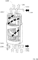
- the system 1400 includes a distribution zone 1410, a generator module 1420 (also called generator) and a rectifier module 1430 (also called rectifier).
- the system 1400 is configured to receive a rich solution 120 in second fluid, described in more detail later, and, by successive heat exchanges, separate the rich solution 120 into a poor solution 110 in second fluid and a cooling solution 130, preferably as concentrated as possible in the second fluid.
- the rich solution 120 thus enters the distribution zone 1410, and falls at least in part into the generator module 1420.
- Vapors 120a have a higher concentration of second fluid. What is not evaporated at generator module 1420 exits through system output 1401, equivalently output 1422 of generator module 1420, to form lean solution 110.
- the vapors heated by the generator module 1420 rise to the distribution zone 1410 and make it possible to heat the rich solution, to initiate phase separation from the distribution zone 1410.
- the inlet 1210 of the lean solution 110 can be fluidically connected to the outlet 1422 of the generator module 1420, preferably via the second heat exchange device and then the expansion valve 410, as described below.
- the inlet 1210 of the lean solution 110 may further be fluidically connected to the outlet 1720 of the evaporator module 1700, preferably via the third heat exchange device 1600.
- the inlet 1210 of the first heat exchange device 1200 can thus allow a mixture between the lean solution 110 and the cooling solution 130.
- an absorption of the vapor of the cooling solution 130 in the liquid phase of the lean solution 110 can occur, in particular in the low pressure part of the first heat exchange device 1200.
- the rich solution 120 before its entry into the system 1400, can be further heated by the lean solution 110.
- This heat exchange then occurs at a high temperature and has advantages in terms of irreversibility.
- the temperatures involved in this exchange thermal are both high, and relatively close to each other. This makes it possible to use the temperatures at the output of this heat exchange to carry out other heat exchanges. For example, the coldest temperature of the poor solution 110, at the outlet of the second device 1300 remains hot enough to be cooled at least once again during a heat exchange to come, for example in the first heat exchange device 1200.
- the rich solution 120 then enters the first heat exchange device 1200 to be heated there.
- the rich solution 120 continues its circulation as far as the pre-rectifier module 1440 as heat transfer fluid for this module.
- the rich solution 120 is then heated by heat exchange with the mixture coming from the distribution zone 1410.
- the rich solution 120 then continues its circulation in the second heat exchange device 1300.
- the rich solution 120 can undergo at least partial desorption making it two-phase, by its thermal interaction with the lean solution 110, circulating in counter-current in the second heat exchange device 1300.
- the rich solution 120 can then be two-phase on leaving the second heat exchange device 1300.
- the solution can become at least partially diphasic.
Landscapes
- Engineering & Computer Science (AREA)
- Physics & Mathematics (AREA)
- Mechanical Engineering (AREA)
- Thermal Sciences (AREA)
- General Engineering & Computer Science (AREA)
- Chemical & Material Sciences (AREA)
- Materials Engineering (AREA)
- Sorption Type Refrigeration Machines (AREA)
- Heat-Exchange Devices With Radiators And Conduit Assemblies (AREA)
Abstract
L'invention concerne un système (1400) de génération et rectification de vapeur et la machine à absorption (1000) associée. Le système (1400) comprend une zone de distribution (1410), un module générateur (1420) de chaleur comprenant un échangeur thermique à plaques en spirale, un module rectifieur (1430) comprenant un deuxième échangeur thermique à plaques en spirale. La zone de distribution (1410) est située entre le module générateur (1420) et le module rectifieur (1430), de sorte que, du module générateur (1420) au module rectifieur (1430) le premier fluide de la solution riche (120) se condense, et le deuxième fluide de la solution riche (120) s'évapore. Le système permet d'obtenir de façon compacte et améliorée la solution pauvre (110) en sortie du module générateur (1420) et la solution réfrigérante (130) en sortie du module rectifieur (1430).The invention relates to a system (1400) for generating and rectifying steam and the associated absorption machine (1000). The system (1400) includes a distribution zone (1410), a heat generator module (1420) including a spiral plate heat exchanger, a rectifier module (1430) including a second spiral plate heat exchanger. The distribution zone (1410) is located between the generator module (1420) and the rectifier module (1430), so that, from the generator module (1420) to the rectifier module (1430) the first fluid of the rich solution (120) condenses, and the second fluid of the rich solution (120) evaporates. The system makes it possible to obtain in a compact and improved manner the lean solution (110) at the output of the generator module (1420) and the cooling solution (130) at the output of the rectifier module (1430).
Description
La présente invention concerne le domaine des machines à absorption. Elle trouve pour application particulièrement avantageuse le domaine des machines à absorption ammoniac-eau pour la production de froid et/ou de chaud.The present invention relates to the field of absorption machines. It finds a particularly advantageous application in the field of ammonia-water absorption machines for the production of cold and/or heat.
Dans un contexte environnemental toujours plus délicat d'un point de vue énergétique, la valorisation de la chaleur industrielle et l'optimisation des consommations du résidentiel sont des passages clés de la transition écologique. Les politiques énergétiques actuelles poussent dans cette direction et soulignent l'importance de la gestion des échanges thermiques, soit froids soit chauds, dans les immeubles, les bâtiments industriels et même dans les zones rurales.In an increasingly delicate environmental context from an energy point of view, the recovery of industrial heat and the optimization of residential consumption are key steps in the ecological transition. Current energy policies push in this direction and emphasize the importance of managing heat exchanges, either cold or hot, in buildings, industrial buildings and even in rural areas.
Il existe diverses solutions technologiques dont plusieurs se basant sur les principes de la thermodynamique.There are various technological solutions, many of which are based on the principles of thermodynamics.
Par exemple, la machine à absorption eau-ammoniac, grâce à son principe de fonctionnement, permet de réaliser un circuit frigorifique ou de pompe à chaleur en utilisant comme source d'énergie de la chaleur à moyenne-haute température au lieu de l'énergie électrique. En effet, l'énergie électrique est généralement couteuse, alors que la chaleur peut être moins onéreuse, voire résulter comme rejet d'un procédé industriel.For example, the water-ammonia absorption machine, thanks to its principle of operation, makes it possible to carry out a refrigeration or heat pump circuit using medium-high temperature heat as an energy source instead of energy. electric. Indeed, electrical energy is generally expensive, while heat can be less expensive, or even result as a waste from an industrial process.
Ainsi, une machine à absorption peut facilement être couplée à des systèmes solaires thermiques, des réseaux de chaleur, des usines industrielles qui nécessitent du froid négatif et même des générateurs électriques turbo-gaz de grosse puissance.Thus, an absorption machine can easily be coupled with solar thermal systems, heat networks, industrial plants that require negative cold and even high-power turbo-gas electric generators.
Toutefois, les systèmes à architecture avancée, par exemple de type échangeur de chaleur générateur-absorbeur, en anglais Generator-Absorber heat eXchanger (abrégé GAX dans la suite) rencontrent des freins à leur déploiement et les machines à architecture standard atteignent déjà leur limite de performance. Pour offrir une alternative viable industriellement et économiquement, les machines à absorption doivent faire l'objet d'améliorations, visant notamment à améliorer la performance, la compacité, baisser le coût et augmenter l'amplitude des conditions opérationnelles.However, systems with advanced architecture, for example of the generator-absorber heat exchanger type, in English Generator-Absorber heat eXchanger (abbreviated GAX in the following) encounter obstacles to their deployment and machines with standard architecture are already reaching their limit of performance. To offer an industrially and economically viable alternative, absorption machines must be subject to improvements, aimed in particular at improving performance, compactness, lowering the cost and increasing the amplitude of the operational conditions.
Le document
Le document
Un objet de la présente invention est donc de proposer une machine à absorption améliorée et performante en conciliant les nécessités techniques et économiques.An object of the present invention is therefore to provide an improved and efficient absorption machine by reconciling technical and economic requirements.
Les autres objets, caractéristiques et avantages de la présente invention apparaîtront à l'examen de la description suivante et des dessins d'accompagnement. Il est entendu que d'autres avantages peuvent être incorporés.The other objects, features and advantages of the present invention will become apparent from a review of the following description and the accompanying drawings. It is understood that other benefits may be incorporated.
Pour atteindre cet objectif, selon un premier aspect on prévoit un système de génération et rectification de vapeur pour machine à absorption, dans lequel circule un mélange comprenant un premier fluide et un deuxième fluide, le mélange présentant une concentration massique en deuxième fluide variant en fonction de sa position dans le système de façon à définir pour le mélange, en fonction de sa position, au moins une solution dite pauvre en deuxième fluide, une solution dite riche en deuxième fluide, et une solution dite réfrigérante.To achieve this objective, according to a first aspect, a system for generating and rectifying steam for an absorption machine is provided, in which circulates a mixture comprising a first fluid and a second fluid, the mixture having a mass concentration of second fluid varying according to its position in the system so as to define for the mixture, as a function of its position, at least one so-called solution poor in second fluid, one so-called rich solution in second fluid, and one so-called refrigerant solution.
Avantageusement, le système comprend, au moins :
- une zone de distribution comprenant une entrée de la solution riche, destinée à être raccordée à un circuit d'une machine à absorption dans lequel circule le mélange,
- un module générateur de chaleur comprenant un premier échangeur thermique à plaques en spirale configuré pour chauffer le mélange issu de la zone de distribution, et comprenant une sortie de la solution pauvre,
- un module rectifieur comprenant un deuxième échangeur thermique à plaques en spirale configuré pour refroidir le mélange issu de la zone de distribution, et comprenant une sortie de la solution réfrigérante.
- a distribution zone comprising an inlet for the rich solution, intended to be connected to a circuit of an absorption machine in which the mixture circulates,
- a heat generator module comprising a first heat exchanger with spiral plates configured to heat the mixture coming from the distribution zone, and comprising an outlet for the lean solution,
- a rectifier module comprising a second heat exchanger with spiral plates configured to cool the mixture coming from the distribution zone, and comprising an outlet for the cooling solution.
La zone de distribution est située, selon une projection sur un axe vertical, entre le module générateur et le module rectifieur, la zone de distribution, le module générateur et le module rectifieur étant configurés de sorte que, du module générateur au module rectifieur :
- le premier fluide de la solution riche se condense,
- le deuxième fluide de la solution riche s'évapore,
- the first fluid of the rich solution condenses,
- the second fluid from the rich solution evaporates,
La zone de distribution est « située » entre le module générateur et le module rectifieur, ne signifie pas uniquement « situé fluidiquement entre » mais spatialement située entre. La zone de distribution est ainsi définie entre le module générateur et le module rectifieur et permet de distribuer la solution riche avec un condensat qui descend vers le module générateur et la vapeur qui remonte vers le module rectifieur. Un échange de chaleur entre le condensat et la vapeur dans cette zone de distribution permet de récupérer de l'énergie portée par la vapeur issue du générateur tout en purifiant sa concentration en deuxième fluide.The distribution zone is "located" between the generator module and the rectifier module, does not only mean "fluidically located between" but spatially located between. The distribution zone is thus defined between the generator module and the rectifier module and makes it possible to distribute the rich solution with a condensate which descends towards the generator module and the steam which rises towards the rectifier module. A heat exchange between the condensate and the steam in this distribution zone makes it possible to recover the energy carried by the steam coming from the generator while purifying its concentration in the second fluid.
Les échangeurs à plaques en spirale permettent en outre d'améliorer les échange thermiques en augmentant la surface d'échange de la vapeur et le condensat avec des fluides caloporteurs circulant dans les échangeurs. Le système de génération et de rectification permet ainsi un meilleur échange thermique et une meilleure séparation de phase du premier et du deuxième fluide, par rapport aux solutions existantes.Spiral plate exchangers also improve heat exchange by increasing the exchange surface of steam and condensate with heat transfer fluids circulating in the exchangers. The generation and rectification system thus allows better heat exchange and better phase separation of the first and second fluids, compared to existing solutions.
Les échangeurs à plaques en spirale permettent en outre une mutualisation des modules générateur et rectifieur en une seule colonne. L'utilisation des échangeurs à plaques en spirale permet d'obtenir une machine compacte avec une quantité limitée de composant. Les échanges thermiques et la séparation de phase pour obtenir séparément la solution réfrigérante et la solution pauvre sont en effet réalisés au même temps, sans nécessiter de bouteilles de séparation comme c'est le cas par exemple dans les solutions comprenant des échangeurs à plaques standard dans les modules générateur et rectifieur.The spiral plate exchangers also allow pooling of the generator and rectifier modules in a single column. The use of spiral plate heat exchangers makes it possible to obtain a compact machine with a limited quantity of components. The heat exchanges and the phase separation to obtain the refrigerant solution and the lean solution separately are in fact carried out at the same time, without requiring separation bottles as is the case for example in the solutions comprising standard plate exchangers in generator and rectifier modules.
Notamment du fait de cette amélioration des échanges thermiques, la compacité de chaque module et donc du système de génération et de rectification de vapeur est améliorée, notamment par rapport aux solutions utilisant des échangeurs en film tombant ou à serpentin. Les échangeurs en film tombant ou à serpentin occupent en effet beaucoup d'espace et l'ajout d'un module rectifieur au sommet augmente encore l'encombrement associé à la colonne.In particular because of this improvement in heat exchange, the compactness of each module and therefore of the steam generation and rectification system is improved, in particular compared to solutions using falling film or coil exchangers. Falling film or serpentine exchangers take up a lot of space and the addition of a rectifier module at the top further increases the bulk associated with the column.
De plus, cela permet de faciliter l'inspection, la substitution et la maintenance des pièces du système.In addition, it allows easy inspection, replacement and maintenance of system parts.
Selon un exemple, la zone de distribution, le module générateur et le module rectifieur sont situés dans une enveloppe formant une colonne. Selon un exemple, la zone de distribution, le module générateur et le module rectifieur sont répartis verticalement dans l'enveloppe. Selon un exemple, la zone de distribution, le module générateur et le module rectifieur sont superposés selon une direction principale d'extension de l'enveloppe.According to one example, the distribution zone, the generator module and the rectifier module are located in an envelope forming a column. According to one example, the distribution zone, the generator module and the rectifier module are distributed vertically in the envelope. According to one example, the distribution zone, the generator module and the rectifier module are superimposed along a main direction of extension of the envelope.
Un deuxième aspect concerne une machine à absorption comprenant un mélange en circulation dans un circuit, le mélange comprenant un premier fluide et un deuxième fluide, la machine présentant une première configuration de production de froid et une deuxième configuration de production de chaleur, le mélange en circulation présentant une concentration massique en deuxième fluide variant en fonction de sa position dans le circuit de sorte à définir pour le mélange en circulation, en fonction de la position, une solution dite pauvre, une solution dite riche, et une solution dite réfrigérante, la machine comprenant au moins :
- un module absorbeur configuré pour augmenter le taux de concentration massique du deuxième fluide de la solution pauvre de façon à transformer la solution pauvre en solution riche,
- un premier dispositif d'échange thermique configuré pour faire interagir thermiquement la solution riche à partir de la température de la solution pauvre,
- le système de génération et rectification de vapeur pour machine à absorption selon le premier aspect, configuré pour transformer la solution riche de façon à obtenir la solution pauvre en sortie du module générateur et la solution réfrigérante en sortie du module rectifieur,
- un module condenseur configuré pour condenser la solution réfrigérante issue du module rectifieur du système,
- un module évaporateur configuré pour évaporer au moins en partie la solution réfrigérante issue du module condenseur.
- an absorber module configured to increase the mass concentration rate of the second fluid of the lean solution so as to transform the lean solution into a rich solution,
- a first heat exchange device configured to cause the rich solution to thermally interact based on the temperature of the lean solution,
- the system for generating and rectifying steam for an absorption machine according to the first aspect, configured to transform the rich solution so as to obtain the lean solution at the outlet of the generator module and the refrigerant solution at the outlet of the rectifier module,
- a condenser module configured to condense the refrigerant solution from the rectifier module of the system,
- an evaporator module configured to at least partially evaporate the refrigerant solution from the condenser module.
Dans la première configuration, la machine est configurée pour refroidir un fluide caloporteur extérieur circulant dans le module évaporateur.In the first configuration, the machine is configured to cool an external heat transfer fluid circulating in the evaporator module.
Dans la deuxième configuration, un fluide caloporteur extérieur circule dans le module absorbeur et un fluide caloporteur extérieur circule dans le module condenseur, la machine étant configurée pour augmenter la température d'au moins un et de préférence de chacun desdits fluide caloporteur extérieur.In the second configuration, an external heat transfer fluid circulates in the absorber module and an external heat transfer fluid circulates in the condenser module, the machine being configured to increase the temperature of at least one and preferably of each of said external heat transfer fluid.
Le taux de concentration massique du deuxième fluide de la solution pauvre est plus particulièrement augmenté par absorption de la solution réfrigérante dans le module absorbeur.The rate of mass concentration of the second fluid of the lean solution is more particularly increased by absorption of the cooling solution in the absorber module.
Selon un exemple, le fluide caloporteur extérieur circulant dans le module absorbeur et le fluide caloporteur extérieur circulant dans le module condenseur forment un même fluide caloporteur extérieur, dit fluide caloporteur extérieur commun. La machine est alors configurée pour augmenter la température du fluide caloporteur extérieur commun.According to one example, the external heat transfer fluid circulating in the absorber module and the external heat transfer fluid circulating in the condenser module form the same external heat transfer fluid, called common external heat transfer fluid. The machine is then configured to increase the temperature of the common external heat transfer fluid.
La machine à absorption présente les effets et avantages décrits relativement au système selon le premier aspect. La machine à absorption permet en outre de réduire l'encombrement des machines classiques.The absorption machine has the effects and advantages described with respect to the system according to the first aspect. The absorption machine also makes it possible to reduce the size of conventional machines.
La machine à absorption offre en outre une double fonction : une fonction frigorifique et une fonction de pompe à chaleur.The absorption machine also offers a double function: a cooling function and a heat pump function.
De plus, l'inspection de la machine est facilitée, ainsi que la substitution et la maintenance des pièces de la machine.In addition, the inspection of the machine is facilitated, as well as the substitution and maintenance of machine parts.
La machine permet par ailleurs d'atteindre des coefficients de performance plus élevés que les solutions existantes.The machine also makes it possible to achieve higher coefficients of performance than existing solutions.
Un troisième aspect concerne un procédé d'utilisation du système de génération et de rectification de vapeur selon le premier aspect.A third aspect relates to a method of using the vapor generation and rectification system according to the first aspect.
Un quatrième aspect concerne un procédé d'utilisation de la machine à absorption selon le deuxième aspect pour la production de froid et/ou la production de chaleur.A fourth aspect relates to a method of using the absorption machine according to the second aspect for the production of cold and/or the production of heat.
Les buts, objets, ainsi que les caractéristiques et avantages de l'invention ressortiront mieux de la description détaillée d'un mode de réalisation de cette dernière qui est illustré par les dessins d'accompagnement suivants dans lesquels :
- La
figure 1 représente une vue d'ensemble d'un exemple de système de génération et de rectification de vapeur selon l'invention. - Les
figures 2A et2B représentent des vues de principe d'un exemple d'échangeur à plaques en spirale. - Les
figures 3A et3B représentent respectivement le module générateur et le module rectifieur selon des exemples de réalisation. - La
figure 4 représente un schéma d'un mode de réalisation selon la présente invention d'une machine à absorption dans une configuration de production de froid. - La
figure 5 représente un schéma d'un mode de réalisation selon la présente invention d'une machine à absorption dans une configuration de production de chaleur.
- The
figure 1 shows an overview of an example of a steam generation and rectification system according to the invention. - The
figure 2A and2B show principle views of an example of a spiral plate heat exchanger. - The
figure 3A and3B respectively represent the generator module and the rectifier module according to exemplary embodiments. - The
figure 4 shows a diagram of an embodiment according to the present invention of an absorption machine in a cold production configuration. - The
figure 5 shows a diagram of an embodiment according to the present invention of an absorption machine in a heat production configuration.
Les dessins sont donnés à titre d'exemples et ne sont pas limitatifs de l'invention. Ils constituent des représentations schématiques de principe destinées à faciliter la compréhension de l'invention et ne sont pas nécessairement à l'échelle des applications pratiques. En particulier les dimensions ne sont pas représentatives de la réalité.The drawings are given by way of examples and do not limit the invention. They constitute schematic representations of principle intended to facilitate understanding of the invention and are not necessarily at the scale of practical applications. In particular the dimensions are not representative of reality.
Avant d'entamer une revue détaillée de modes de réalisation de l'invention, sont énoncées ci-après des caractéristiques optionnelles de l'un quelconque des aspects de l'invention, qui peuvent éventuellement être utilisées en association ou alternativement.Before commencing a detailed review of embodiments of the invention, optional features of any one of the aspects of the invention are set forth below, which may optionally be used in combination or alternatively.
Selon un exemple, le premier fluide comprend de l'eau et/ou un solvant tel que le nitrate de lithium ou le thiocyanate de sodium, et dans laquelle le deuxième fluide comprend de l'ammoniac ou de l'alcool, de préférence le premier fluide est de l'eau et le deuxième fluide est de l'ammoniac.According to one example, the first fluid comprises water and/or a solvent such as lithium nitrate or sodium thiocyanate, and in which the second fluid comprises ammonia or alcohol, preferably the first fluid is water and the second fluid is ammonia.
Selon un exemple, le système comprend en outre un module pré-rectifieur comprenant de préférence un troisième échangeur thermique à plaques en spirale et disposé entre la zone de distribution et le module rectifieur. Le module pré-rectifieur peut être configuré pour refroidir le mélange issu de la zone de distribution. Ainsi, le module pré-rectifieur permet d'améliorer encore la séparation entre les premier et deuxième fluides en ajoutant un niveau d'échange thermique supplémentaire. La qualité de la solution réfrigérante et ainsi encore améliorée en sortie du système, ce qui permet d'améliorer le coefficient de performance de la machine à absorption.According to one example, the system further comprises a pre-rectifier module preferably comprising a third heat exchanger with spiral plates and placed between the distribution zone and the rectifier module. The pre-rectifier module can be configured to cool the mixture coming from the distribution zone. Thus, the pre-rectifier module makes it possible to further improve the separation between the first and second fluids by adding an additional heat exchange level. The quality of the cooling solution and so on improved at the output of the system, which makes it possible to improve the coefficient of performance of the absorption machine.
Selon un exemple, la zone de distribution, le module générateur, le module pré-rectifieur et le module rectifieur sont situés dans une enveloppe formant une colonne. Selon un exemple, la zone de distribution, le module générateur, le module pré-rectifieur et le module rectifieur sont répartis verticalement dans l'enveloppe. Selon un exemple, la zone de distribution, le module générateur, le module pré-rectifieur et le module rectifieur sont superposés selon une direction principale d'extension de l'enveloppe.According to one example, the distribution zone, the generator module, the pre-rectifier module and the rectifier module are located in an envelope forming a column. According to one example, the distribution zone, the generator module, the pre-rectifier module and the rectifier module are distributed vertically in the envelope. According to one example, the distribution zone, the generator module, the pre-rectifier module and the rectifier module are superimposed along a main direction of extension of the envelope.
Selon un exemple, le premier échangeur thermique à plaques en spirale et le deuxième échangeur thermique à plaques en spirale sont distincts et de préférence distants l'un de l'autre.According to one example, the first spiral plate heat exchanger and the second spiral plate heat exchanger are separate and preferably spaced from each other.
Selon un exemple, le premier échangeur thermique à plaques en spirale et le troisième échangeur thermique à plaques en spirale sont distincts et de préférence distants l'un de l'autre.According to one example, the first spiral plate heat exchanger and the third spiral plate heat exchanger are separate and preferably spaced from each other.
Selon un exemple, le premier échangeur thermique à plaques en spirale, le deuxième échangeur thermique à plaques en spirale et le troisième échangeur thermique à plaques en spirale sont distincts et de préférence distants l'un de l'autre.According to one example, the first spiral plate heat exchanger, the second spiral plate heat exchanger and the third spiral plate heat exchanger are separate and preferably spaced from each other.
Selon un exemple, la solution pauvre présente un premier taux de concentration massique en deuxième fluide, la solution riche présente un deuxième taux de concentration massique en deuxième fluide, et la solution réfrigérante présente un troisième taux de concentration massique en deuxième fluide. Le premier taux de concentration, le deuxième taux de concentration, et le troisième taux de concentration peuvent être chacun différents les uns des autres. Le premier taux de concentration peut être inférieur au deuxième taux de concentration. Le premier taux de concentration et le deuxième taux de concentration peuvent être inférieurs au troisième taux de concentration.According to one example, the lean solution has a first rate of mass concentration of second fluid, the rich solution has a second rate of mass concentration of second fluid, and the cooling solution has a third rate of mass concentration of second fluid. The first level of concentration, the second level of concentration, and the third level of concentration can each be different from each other. The first level of concentration may be lower than the second level of concentration. The first level of concentration and the second level of concentration may be lower than the third level of concentration.
Selon un exemple, la machine à absorption comprend en outre un troisième dispositif d'échange thermique configuré pour faire interagir thermiquement la solution réfrigérante avant son entrée dans le module évaporateur avec la solution réfrigérante après sa sortie du module évaporateur.According to one example, the absorption machine further comprises a third heat exchange device configured to cause the cooling solution to thermally interact before it enters the evaporator module with the cooling solution after it leaves the evaporator module.
Selon un exemple, au moins l'un parmi le module absorbeur, le premier dispositif d'échange thermique, le module condenseur, le module évaporateur comprend au moins un échangeur thermique à plaques.According to one example, at least one of the absorber module, the first heat exchange device, the condenser module, the evaporator module comprises at least one plate heat exchanger.
L'utilisation d'échangeur à plaques permet de réduire l'encombrement des machines à absorption de l'art antérieur, notamment par rapport aux échangeurs à film ou a serpentins. Cela permet en outre de réduire les coûts de fabrication des machines à absorption de l'art antérieur, ainsi qu'une maintenance plus simple.The use of plate heat exchangers makes it possible to reduce the size of absorption machines of the prior art, in particular with respect to film or coil heat exchangers. This also makes it possible to reduce the manufacturing costs of absorption machines of the prior art, as well as simpler maintenance.
Selon cet exemple, un échangeur thermique à plaques et de préférence chaque échangeur à plaques est configuré pour que les fluides le traversant circulent en contre-courant les uns relativement aux autres. Ainsi, les échanges thermiques sont améliorés.According to this example, a plate heat exchanger and preferably each plate exchanger is configured so that the fluids passing through it circulate in countercurrent relative to each other. Thus, the heat exchanges are improved.
Selon un exemple, le module absorbeur comprend :
- une entrée de la solution pauvre, la solution pauvre présentant une première température,
- une sortie de la solution riche, la solution riche présentant une deuxième température de préférence inférieure à la première température,
- une entrée d'un premier fluide caloporteur extérieur, et
- une sortie du premier fluide caloporteur extérieur.
- an inlet of the poor solution, the poor solution having a first temperature,
- an outlet of the rich solution, the rich solution having a second temperature preferably lower than the first temperature,
- an inlet of a first external heat transfer fluid, and
- an outlet of the first external heat transfer fluid.
Selon un exemple, le module absorbeur est configuré pour faire interagir thermiquement un mélange de la solution pauvre et de la solution réfrigérante avec le premier fluide caloporteur extérieur de sorte à transformer le mélange de la solution pauvre et de la solution réfrigérante en solution riche. De préférence, le module absorbeur est configuré pour diminuer la température du mélange de la solution pauvre et de la solution réfrigérante, de façon à augmenter le taux de concentration massique du deuxième fluide pour transformer la solution pauvre en solution riche.According to one example, the absorber module is configured to cause a mixture of the lean solution and of the refrigerant solution to interact thermally with the first external heat transfer fluid so as to transform the mixture of the lean solution and of the refrigerant solution into a rich solution. Preferably, the absorber module is configured to reduce the temperature of the mixture of the lean solution and of the cooling solution, so as to increase the rate of mass concentration of the second fluid to transform the lean solution into a rich solution.
Selon un exemple, le premier dispositif d'échange thermique comprend :
- une entrée de la solution pauvre,
- une sortie de la solution pauvre,
- une entrée de la solution riche, et
- une sortie de la solution riche.
- an input of the poor solution,
- an output of the poor solution,
- an input of the rich solution, and
- a rich solution output.
Selon un exemple, le premier dispositif d'échange thermique est configuré pour augmenter la température de la solution riche à partir de la température de la solution pauvre. La température de la solution riche est de préférence inférieure à la température de la solution pauvre au niveau du premier dispositif d'échange thermique.According to one example, the first heat exchange device is configured to increase the temperature of the rich solution from the temperature of the lean solution. The temperature of the rich solution is preferably lower than the temperature of the lean solution at the level of the first heat exchange device.
Selon un exemple, l'entrée de la solution riche du premier dispositif d'échange thermique est fluidiquement connectée à la sortie de la solution riche du module absorbeur, et la sortie de la solution pauvre du premier dispositif d'échange thermique est fluidiquement connectée à l'entrée de la solution pauvre du module absorbeur.According to one example, the rich solution inlet of the first heat exchange device is fluidically connected to the rich solution outlet of the absorber module, and the lean solution outlet of the first heat exchange device is fluidically connected to the weak solution inlet of the absorber module.
Selon un exemple, le système de génération et rectification de vapeur comprend :
- une zone de distribution comprenant l'entrée de la solution riche,
- un module générateur comprenant la sortie de la solution pauvre, et
- un module rectifieur comprenant la sortie de la solution réfrigérante.
- a distribution zone comprising the inlet of the rich solution,
- a generator module comprising the weak solution output, and
- a rectifier module comprising the output of the cooling solution.
Le système de génération et rectification de vapeur est configuré pour séparer la solution riche la solution réfrigérante et la solution pauvre.The vapor generation and rectification system is configured to separate the rich solution from the refrigerant solution and the lean solution.
Selon un exemple, l'entrée de la solution riche de la zone de distribution est fluidiquement connectée à la sortie de la solution riche du premier dispositif d'échange thermique.According to one example, the inlet of the rich solution of the distribution zone is fluidically connected to the outlet of the rich solution of the first heat exchange device.
Selon un exemple, le module générateur est configuré pour faire interagir thermiquement le mélange issu de la zone de distribution et un deuxième fluide caloporteur extérieur de sorte à augmenter la température du mélange.According to one example, the generator module is configured to thermally interact the mixture coming from the distribution zone and a second external heat transfer fluid so as to increase the temperature of the mixture.
Selon un exemple, le module rectifieur est configuré pour faire interagir thermiquement le mélange issu de la zone de distribution et un troisième fluide caloporteur extérieur de sorte à augmenter la température du mélange.According to one example, the rectifier module is configured to thermally interact the mixture coming from the distribution zone and a third external heat transfer fluid so as to increase the temperature of the mixture.
Selon un exemple, le module condenseur comprend :
- une entrée de la solution réfrigérante,
- une sortie de la solution réfrigérante,
- une entrée d'un quatrième fluide caloporteur extérieur, et
- une sortie du quatrième fluide caloporteur extérieur.
- an inlet for the cooling solution,
- an outlet for the cooling solution,
- an inlet of a fourth external heat transfer fluid, and
- an outlet of the fourth external heat transfer fluid.
Selon un exemple, le module condenseur est configuré pour faire interagir thermiquement la solution réfrigérante et le quatrième fluide caloporteur extérieur de façon à condenser la solution réfrigérante.According to one example, the condenser module is configured to cause the cooling solution and the fourth external heat transfer fluid to thermally interact so as to condense the cooling solution.
Selon un exemple, l'entrée de la solution réfrigérante du module condenseur est fluidiquement connectée à la sortie de la solution réfrigérante du module rectifieur.According to one example, the inlet of the cooling solution of the condenser module is fluidically connected to the outlet of the cooling solution of the rectifier module.
Selon un exemple, le module évaporateur comprend :
- une entrée de la solution réfrigérante,
- une sortie de la solution réfrigérante,
- une entrée d'un cinquième fluide caloporteur extérieur,
- une sortie du cinquième fluide caloporteur extérieur.
- an inlet for the cooling solution,
- an outlet for the cooling solution,
- an inlet of a fifth external heat transfer fluid,
- an outlet of the fifth external heat transfer fluid.
Selon un exemple, le module évaporateur est configuré pour faire interagir thermiquement la solution réfrigérante et le cinquième fluide caloporteur extérieur de façon à modifier, de préférence à diminuer, la température du quatrième fluide caloporteur extérieur par l'évaporation d'une partie au moins de la solution réfrigérante.According to one example, the evaporator module is configured to cause the cooling solution and the fifth external heat transfer fluid to thermally interact so as to modify, preferably to decrease, the temperature of the fourth external heat transfer fluid by the evaporation of at least part of the cooling solution.
Selon un exemple, l'entrée de la solution réfrigérante du module évaporateur est fluidiquement connectée à la sortie de la solution réfrigérante du module condenseur, et la sortie de la solution réfrigérante du module évaporateur est fluidiquement connectée à l'entrée de la solution pauvre du module absorbeur.According to one example, the inlet of the refrigerant solution of the evaporator module is fluidically connected to the outlet of the refrigerant solution of the condenser module, and the outlet of the refrigerant solution of the evaporator module is fluidically connected to the inlet of the lean solution of the absorber module.
Selon un exemple, dans la première configuration, la machine est configurée pour refroidir le cinquième fluide caloporteur extérieur.According to one example, in the first configuration, the machine is configured to cool the fifth external heat transfer fluid.
Selon un exemple, dans la deuxième configuration, la machine est configurée pour augmenter la température d'au moins un parmi, et de préférence de chacun parmi, le premier fluide caloporteur extérieur et le quatrième fluide caloporteur extérieur.According to an example, in the second configuration, the machine is configured to increase the temperature of at least one of, and preferably of each of, the first external heat transfer fluid and the fourth external heat transfer fluid.
Selon un exemple, dans la deuxième configuration, la machine est configurée pour augmenter la température d'au moins un parmi, et de préférence de chacun parmi, le premier fluide caloporteur extérieur, le troisième fluide caloporteur et le quatrième fluide caloporteur extérieur.According to one example, in the second configuration, the machine is configured to increase the temperature of at least one of, and preferably of each of, the first external heat transfer fluid, the third heat transfer fluid and the fourth external heat transfer fluid.
Selon un exemple, le premier fluide caloporteur extérieur et le quatrième fluide caloporteur extérieur forment un seul et même fluide caloporteur extérieur commun :
- la sortie du premier fluide caloporteur extérieur du module absorbeur étant fluidiquement connectée, de préférence directement, à l'entrée du quatrième fluide caloporteur extérieur du module condenseur et/ou
- l'entrée du premier fluide caloporteur extérieur du module absorbeur est fluidiquement connectée, de préférence directement, à la sortie du quatrième fluide caloporteur extérieur du module condenseur.
- the outlet of the first external heat transfer fluid of the absorber module being fluidically connected, preferably directly, to the inlet of the fourth external heat transfer fluid of the condenser module and/or
- the inlet of the first external heat transfer fluid of the absorber module is fluidically connected, preferably directly, to the output of the fourth external heat transfer fluid of the condenser module.
La récupération thermique de la machine absorption dans la configuration de production de chaleur est ainsi améliorée.The thermal recovery of the absorption machine in the heat production configuration is thus improved.
Selon un exemple, le premier fluide caloporteur extérieur, le troisième fluide caloporteur extérieur, et le quatrième fluide caloporteur extérieur forment un seul et même fluide caloporteur extérieur commun.According to one example, the first external heat transfer fluid, the third external heat transfer fluid, and the fourth external heat transfer fluid form one and the same common external heat transfer fluid.
Selon un exemple, la sortie de la solution réfrigérante du module évaporateur est fluidiquement connectée à l'entrée de la solution pauvre du module absorbeur, la solution pauvre et la solution réfrigérante étant mélangées en amont ou au niveau de l'entrée de la solution pauvre du premier dispositif d'échange thermique.According to one example, the outlet of the refrigerant solution of the evaporator module is fluidically connected to the inlet of the lean solution of the absorber module, the lean solution and the refrigerant solution being mixed upstream or at the inlet of the lean solution of the first heat exchange device.
Selon un exemple, la machine à absorption comprend en outre un deuxième dispositif d'échange thermique configuré pour faire interagir thermiquement la solution riche à partir de la température de la solution pauvre.According to one example, the absorption machine further comprises a second heat exchange device configured to cause the rich solution to thermally interact from the temperature of the lean solution.
Selon un exemple, le deuxième dispositif d'échange thermique comprend :
- une entrée de la solution riche,
- une sortie de la solution riche,
- une entrée de la solution pauvre, et
- une sortie de la solution pauvre.
- an input of the rich solution,
- an output of the rich solution,
- an input of the poor solution, and
- an output of the poor solution.
Selon un exemple, le deuxième dispositif d'échange thermique est configuré pour faire interagir thermiquement la solution riche avec la solution pauvre, de préférence pour faire augmenter la température de la solution riche à partir de la température de la solution pauvre.According to one example, the second heat exchange device is configured to make thermally interacting the rich solution with the lean solution, preferably to raise the temperature of the rich solution from the temperature of the lean solution.
Selon un exemple, l'entrée de la solution riche du deuxième dispositif d'échange thermique est fluidiquement connectée avec la sortie de la solution riche du premier dispositif d'échange thermique, et la sortie de la solution riche du deuxième dispositif d'échange thermique est fluidiquement connectée à l'entrée de la solution riche de la zone de distribution du système.According to one example, the input of the rich solution of the second heat exchange device is fluidically connected with the output of the rich solution of the first heat exchange device, and the output of the rich solution of the second heat exchange device is fluidly connected to the rich solution inlet of the system's distribution zone.
Selon un exemple, l'entrée de la solution pauvre du deuxième dispositif d'échange thermique est fluidiquement connectée avec la sortie de la solution pauvre du module générateur du système, et la sortie de la solution pauvre du deuxième dispositif d'échange thermique est fluidiquement connectée avec l'entrée de la solution pauvre du premier dispositif d'échange thermique.According to one example, the lean solution inlet of the second heat exchange device is fluidically connected with the lean solution outlet of the generator module of the system, and the lean solution outlet of the second heat exchange device is fluidically connected with the lean solution inlet of the first heat exchange device.
Selon un exemple, le deuxième dispositif d'échange thermique comprend au moins un échangeur thermique à plaques.According to one example, the second heat exchange device comprises at least one plate heat exchanger.
Selon un exemple, la solution pauvre et la solution riche circulent à contre-courant dans l'échangeur thermique à plaques du deuxième dispositif d'échange thermique.According to one example, the lean solution and the rich solution circulate in countercurrent in the plate heat exchanger of the second heat exchange device.
Selon un exemple, le module pré-rectifieur comprend :
- une entrée de la solution riche,
- une sortie de la solution riche.
- an input of the rich solution,
- a rich solution output.
Selon un exemple, le module pré-rectifieur est configuré pour faire interagir thermiquement la solution riche et le mélange issu de la zone de distribution, de façon à refroidir le mélange issu de la zone de distribution, et chauffer la solution riche.According to one example, the pre-rectifier module is configured to cause the rich solution and the mixture coming from the distribution zone to thermally interact, so as to cool the mixture coming from the distribution zone, and heat the rich solution.
Selon un exemple, l'entrée de la solution riche est fluidiquement connectée à la sortie de la solution riche du module absorbeur, et la sortie de la solution riche est fluidiquement connectée à l'entrée de la solution riche de la zone de distribution du système.According to one example, the rich solution inlet is fluidically connected to the rich solution outlet of the absorber module, and the rich solution outlet is fluidically connected to the rich solution inlet of the system distribution zone .
Selon un exemple, la sortie de la solution riche du module pré-rectifieur est fluidiquement connectée à l'entrée de la solution riche du premier dispositif d'échange thermique.According to one example, the output of the rich solution of the pre-rectifier module is fluidically connected to the input of the rich solution of the first heat exchange device.
Selon un exemple, la machine comprenant le deuxième dispositif d'échange thermique, l'entrée de la solution riche du module pré-rectifieur est fluidiquement connectée à la sortie de la solution riche du premier dispositif d'échange thermique, et la sortie de la solution riche du module pré-rectifieur est fluidiquement connectée à l'entrée de la solution riche du deuxième dispositif d'échange thermique.According to one example, the machine comprising the second heat exchange device, the inlet of the rich solution of the pre-rectifier module is fluidically connected to the outlet of the rich solution of the first heat exchange device, and the outlet of the rich solution of the pre-rectifier module is fluidically connected to the rich solution inlet of the second heat exchange device.
Selon un exemple, le troisième dispositif d'échange thermique comprend :
- une première entrée de la solution réfrigérante,
- une deuxième sortie de la solution réfrigérante,
- une deuxième entrée de la solution réfrigérante, et
- une deuxième sortie de la solution réfrigérante.
- a first inlet of the cooling solution,
- a second outlet for the cooling solution,
- a second inlet of the cooling solution, and
- a second outlet of the cooling solution.
Selon un exemple, le troisième dispositif d'échange thermique est configuré pour faire interagir thermiquement la solution réfrigérante avant son entrée dans le module évaporateur avec la solution réfrigérante après sa sortie du module évaporateur.According to one example, the third heat exchange device is configured to cause the cooling solution to thermally interact before it enters the evaporator module with the cooling solution after it leaves the evaporator module.
Selon un exemple, la première entrée de la solution réfrigérante du troisième dispositif d'échange thermique est fluidiquement connectée à la sortie de la solution réfrigérante du module condenseur, et la première sortie de la solution réfrigérante du troisième dispositif d'échange thermique est fluidiquement connectée à l'entrée de la solution réfrigérante du module évaporateur.According to one example, the first inlet of the refrigerant solution of the third heat exchange device is fluidically connected to the outlet of the refrigerant solution of the condenser module, and the first outlet of the refrigerant solution of the third heat exchange device is fluidically connected at the refrigerant solution inlet of the evaporator module.
Selon un exemple, la deuxième entrée de la solution réfrigérante du troisième dispositif d'échange thermique est fluidiquement connectée à la sortie de la solution réfrigérante du module évaporateur, et la deuxième sortie de la solution réfrigérante du troisième dispositif d'échange thermique est fluidiquement connectée à l'entrée de la solution pauvre du premier dispositif d'échange thermique.According to an example, the second inlet of the refrigerant solution of the third heat exchange device is fluidically connected to the outlet of the refrigerant solution of the evaporator module, and the second outlet of the refrigerant solution of the third heat exchange device is fluidically connected at the lean solution inlet of the first heat exchange device.
Selon un exemple, le troisième dispositif d'échange thermique comprend au moins un échangeur thermique à plaques. Selon cet exemple, la solution réfrigérante sortant du module condenseur et la solution réfrigérante sortant du module évaporateur circulent à contre-courant dans l'échangeur thermique à plaques du troisième dispositif d'échange thermique.According to one example, the third heat exchange device comprises at least one plate heat exchanger. According to this example, the refrigerant solution leaving the condenser module and the refrigerant solution leaving the evaporator module circulate in countercurrent in the plate heat exchanger of the third heat exchange device.
Selon un exemple, la machine comprend en outre un dispositif d'augmentation de pression de la solution réfrigérante fluidiquement connecté entre la sortie de la solution réfrigérante du module évaporateur et l'entrée de la solution pauvre du premier dispositif d'échange thermique, de sorte à augmenter la pression du mélange de la solution pauvre avec la solution réfrigérante dans l'un au moins parmi le premier dispositif d'échange thermique, et le module absorbeur. Le dispositif d'augmentation de pression de la solution réfrigérante permet d'améliorer encore le coefficient de performance de la machine.According to one example, the machine further comprises a device for increasing the pressure of the refrigerant solution fluidly connected between the outlet for the refrigerant solution of the evaporator module and the inlet for the lean solution of the first heat exchange device, so to increase the pressure of the mixture of the lean solution with the refrigerant solution in at least one of the first heat exchange device, and the absorber module. The device for increasing the pressure of the refrigerant solution makes it possible to further improve the coefficient of performance of the machine.
Selon un exemple, la machine comprend en outre au moins une première valve d'expansion comprenant :
- une entrée de la solution pauvre et
- une sortie de la solution pauvre.
- an input of the poor solution and
- an output of the poor solution.
Selon un exemple, la première valve d'expansion est configurée pour modifier la pression de la solution pauvre, de préférence pour modifier la pression de la solution pauvre par une détente isenthalpique,According to one example, the first expansion valve is configured to modify the pressure of the weak solution, preferably to modify the pressure of the weak solution by isenthalpic relaxation,
Selon un exemple, l'entrée de la solution pauvre de la valve d'expansion est fluidiquement connectée à la sortie de la solution pauvre du module générateur, et de préférence à la sortie de la solution pauvre du deuxième dispositif d'échange thermique.According to one example, the lean solution inlet of the expansion valve is fluidically connected to the lean solution outlet of the generator module, and preferably to the lean solution outlet of the second heat exchange device.
Selon un exemple, la machine comprend en outre au moins une deuxième valve d'expansion comprenant :
- une entrée de la solution réfrigérante et
- une sortie de la solution réfrigérante,
- an inlet for the cooling solution and
- an outlet for the cooling solution,
Selon un exemple, la deuxième valve d'expansion est configurée pour modifier la température de la solution réfrigérante, de préférence pour modifier la température de la solution réfrigérante (140) par une détente isenthalpique.According to one example, the second expansion valve is configured to modify the temperature of the refrigerant solution, preferably to modify the temperature of the refrigerant solution (140) by an isenthalpic expansion.
Selon un exemple, l'entrée de la solution réfrigérante de la deuxième valve d'expansion est fluidiquement connectée à la sortie de la solution réfrigérante du module condenseur, de préférence à la première sortie de la solution réfrigérante du troisième dispositif d'échange thermique, et la sortie de la solution réfrigérante est fluidiquement connectée à l'entrée de la solution réfrigérante du module évaporateur.According to one example, the inlet of the coolant solution of the second expansion valve is fluidically connected to the outlet of the coolant solution of the condenser module, preferably to the first outlet of the coolant solution of the third heat exchange device, and the refrigerant solution outlet is fluidly connected to the refrigerant solution inlet of the evaporator module.
Selon un exemple, la machine comprend en outre une pompe à solution comprenant :
- une entrée de la solution riche, et
- une sortie de la solution riche.
- an input of the rich solution, and
- a rich solution output.
Selon un exemple, la pompe à solution est configurée pour modifier la pression de la solution riche, de préférence pour augmenter la pression de la solution riche.According to one example, the solution pump is configured to modify the pressure of the rich solution, preferably to increase the pressure of the rich solution.
Selon un exemple, l'entrée de la solution riche de la pompe à solution est fluidiquement connectée à la sortie de la solution riche du module absorbeur, et la sortie de la solution riche de la pompe à solution est fluidiquement connectée à l'entrée de la solution riche du premier dispositif d'échange thermique.In one example, the rich solution inlet of the solution pump is fluidly connected to the rich solution outlet of the absorber module, and the rich solution outlet of the solution pump is fluidically connected to the inlet of the rich solution of the first heat exchange device.
Il est précisé que dans le cadre de la présente invention, l'expression « A fluidiquement connecté à B » ou encore « A fluidiquement raccordé à B » est synonyme de « A est en connexion fluidique avec B » et ne signifie pas nécessairement qu'il n'existe pas d'organe entre A et B. Ainsi ces expressions s'entendent d'une connexion fluidique entre deux éléments, cette connexion pouvant ou non être directe, cela signifie qu'il est possible qu'entre un premier dispositif et un deuxième dispositif qui sont fluidiquement connectés, un parcours d'un fluide existe, ce parcours pouvant ou non comprendre d'autres dispositifs.It is specified that in the context of the present invention, the expression "A fluidically connected to B" or even "A fluidically connected to B" is synonymous with "A is in fluidic connection with B" and does not necessarily mean that there is no organ between A and B. Thus these expressions refer to a fluidic connection between two elements, this connection possibly or not being direct, this means that it is possible that between a first device and a second device that are fluidly connected, a path of a fluid exists, which path may or may not include other devices.
A l'inverse, dans le cadre de la présente invention, le terme «fluidiquement connecté directement» s'entend d'une connexion fluidique directe entre deux éléments. Cela signifie qu'entre un premier dispositif et un deuxième dispositif qui sont fluidiquement connectés directement aucun autre organe n'est présent, autre qu'un conduit ou plusieurs conduits.Conversely, in the context of the present invention, the term “fluidically connected directly” means a direct fluidic connection between two elements. This means that between a first device and a second device which are fluidly connected directly no other organ is present, other than a duct or several ducts.
Il est précisé que dans le cadre de la présente invention, le terme « fluidiquement disposé » s'entend d'un positionnement d'un dispositif sur le parcours d'un fluide.It is specified that in the context of the present invention, the term “fluidically arranged” means a positioning of a device in the path of a fluid.
Par « échangeur à plaques en spirale » on entend un échangeur thermique comprenant au moins une plaque métallique enroulée, par exemple de façon hélicoïdale, autour d'un axe central de l'échangeur thermique. De préférence, l'échangeur thermique comprend deux plaques métalliques enroulées, par exemple de façon hélicoïdale, l'une par rapport à l'autre.By “spiral plate exchanger” is meant a heat exchanger comprising at least one metal plate wound, for example helically, around a central axis of the heat exchanger. Preferably, the heat exchanger comprises two metal plates wound, for example helically, relative to each other.
Par fluide « extérieur » on entend un fluide distinct, en termes de circulation fluidique, du premier et du deuxième fluide.By “external” fluid is meant a distinct fluid, in terms of fluid circulation, from the first and from the second fluid.
Un aspect de l'invention concerne ainsi une machine à absorption, dans laquelle circule un mélange en un premier fluide et un deuxième fluide, apte à délivrer de la chaleur et/ou du froid en fonction de sa configuration.One aspect of the invention thus relates to an absorption machine, in which circulates a mixture of a first fluid and a second fluid, capable of delivering heat and/or cold depending on its configuration.
Pour rappel l'effet utile dans le cas d'une machine frigorifique est le flux QE cédé par le fluide froid, et plus particulièrement par le fluide caloporteur du module évaporateur. En configuration pompe à chaleur l'effet utile est le flux de chaleur cédé par la machine à un fluide extérieur qui se chauffe. Par exemple, l'effet utile comprend ou est la somme de QA et Qc, les deux flux de chaleur cédés par la machine à un fluide extérieur qui se chauffe, et plus particulièrement les flux cédés au fluide caloporteur du module absorbeur et au fluide du module condenseur, pouvant former un seul et même fluide caloporteur.As a reminder, the useful effect in the case of a refrigerating machine is the flow Q E transferred by the cold fluid, and more particularly by the heat transfer fluid of the evaporator module. In the heat pump configuration, the useful effect is the flow of heat transferred by the machine to an external fluid which heats up. For example, the useful effect includes or is the sum of Q A and Qc, the two heat fluxes transferred by the machine to an external fluid which heats up, and more particularly the fluxes transferred to the heat transfer fluid of the absorber module and to the fluid of the condenser module, which can form a single heat transfer fluid.
Le coût, voire la dépense énergétique nécessaire au roulement de la machine, est constitué par QG et WP, respectivement l'énergie thermique à haute température destinée au générateur et l'énergie électrique nécessaire à la pompe à solution. Étant deux sources d'énergie différentes et non-comparables il faut différencier entre un coefficient de performance (abrégé COP), le COPTH thermique et le COPEL électrique. On définit dans la suite COP comme le COPTH thermique.The cost, or even the energy expenditure necessary for running the machine, is constituted by Q G and W P , respectively the high temperature thermal energy intended for the generator and the electrical energy necessary for the solution pump. Being two different and non-comparable sources of energy, it is necessary to differentiate between a coefficient of performance (abbreviated COP), the thermal COP TH and the electric COP EL . In what follows, COP is defined as the thermal COP TH .
Par exemple, en fonctionnement pour la production de froid au module évaporateur : COPTH = QE / QG.For example, in operation for cold production at the evaporator module: COP TH = Q E / Q G .
Par exemple, en fonctionnement pour la production de chaleur à l'absorbeur et au condenseur: COPTH = (QA + Qc)/ QG.For example, in operation for the production of heat at the absorber and at the condenser: COP TH = (Q A + Qc)/ Q G .
En particulier, la présente invention permet de réaliser au moins un cycle thermodynamique d'absorption de type GAX tout en présentant des avantages à la fois en termes de performances mais également de coût et d'encombrement.In particular, the present invention makes it possible to carry out at least one thermodynamic absorption cycle of the GAX type while presenting advantages both in terms of performance but also of cost and size.
En effet, contrairement à l'art antérieur qui utilise des dispositifs encombrants et verticaux, en particulier des colonnes pourvues d'échangeur à film ou à serpentins qui s'étendent principalement selon la verticale, la présente solution utilise une technologie beaucoup plus compacte et minimisant le nombre de modules et/ou d'élément de la machine.Indeed, unlike the prior art which uses bulky and vertical devices, in particular columns provided with a film or coil exchanger which extend mainly vertically, the present solution uses a technology much more compact and minimizing the number of modules and/or machine elements.
Pour cela, on prévoit un système de génération et de rectification de vapeur dans lequel les échanges thermiques sont notamment réalisés grâce à des échangeurs à plaques en spirales. Les échangeurs à plaques en spirales permettent d'augmenter la surface d'échange thermique et d'améliorer la séparation de phase entre le premier fluide et le deuxième fluide circulant, sans nécessiter d'élément supplémentaires tels que des bouteilles de séparation.For this, a steam generation and rectification system is provided in which the heat exchanges are carried out in particular by means of spiral plate exchangers. Spiral plate exchangers make it possible to increase the heat exchange surface and to improve the phase separation between the first fluid and the second circulating fluid, without requiring additional elements such as separation bottles.
Les différents éléments compris dans le système de génération et de rectification de vapeur, puis les éléments compris dans la machine à absorption sont décrits, avant de décrire le circuit des solutions dans la machine.The different elements included in the steam generation and rectification system, then the elements included in the absorption machine are described, before describing the solution circuit in the machine.
Le système 1400 de génération et de rectification de vapeur est tout d'abord décrit selon un exemple de réalisation illustré par les
Comme par exemple illustré en
Pour cela, le système 1400 comprend une zone de distribution 1410 présentant une entrée 1411 destinée à être raccordée à un circuit de circulation d'une machine à absorption. Ainsi la solution riche 120 entre dans le système 1400 au niveau de la zone de distribution 1410.For this, the
Le système comprend en outre un module générateur 1420 (aussi appelé générateur) et un module rectifieur 1430 (aussi appelé rectifieur), ces modules étant disposés de part et d'autre de la zone de distribution 1410, en projection sur un axe sensiblement vertical. Comme par exemple illustré en
Le module générateur 1420 est configuré pour chauffer le mélange 100 issu de la zone de distribution 1410, de façon à l'évaporer partiellement. Pour cela, le module générateur 1420 comprend un passage de circulation d'un fluide caloporteur extérieur 220, et comprend une entrée 1423 et une sortie 1423 du fluide caloporteur extérieur 220. Le fluide caloporteur présente de préférence une température supérieure à la température du mélange 100 issu de la zone de distribution 1410.The
Le module rectifieur 1430 est configuré pour refroidir le mélange 100 issu de la zone de distribution 1410. Pour cela, le module rectifieur 1430 comprend un passage de circulation d'un fluide caloporteur extérieur 230, comprenant une entrée 1433 et une sortie 1433 du fluide caloporteur 230. Le fluide caloporteur 230 présente de préférence une température inférieure à la température du mélange 100 issu de la zone de distribution 1410.The
La solution riche 120 entre ainsi dans la zone de distribution 1410, et tombe au moins en partie dans le module générateur 1420. La solution étant chauffée, elle s'évapore au moins en partie sous forme de vapeur 120a, décrit plus en détail ci-dessous relativement au fonctionnement des échangeurs à plaques en spirale. Les vapeurs 120a ont une concentration plus grande en deuxième fluide. Ce qui n'est pas évaporé au niveau du module générateur 1420 sort par la sortie 1401 du système, de façon équivalente la sortie 1422 du module générateur 1420, pour former la solution pauvre 110.The
Les vapeurs chauffées par le module générateur 1420 remontent à la zone de distribution 1410 et permettent de chauffer la solution riche, pour amorcer la séparation de phase dès la zone de distribution 1410.The vapors heated by the
Les vapeurs 120a issues du module générateur 1420 et de la zone de distribution 1410 entrent ensuite dans le module rectifieur 1430. Le module rectifieur 1430 est configuré pour refroidir les vapeurs 120a de sorte qu'une partie riche en premier fluide condense sous forme de condensat 120b, et que la partie restante de vapeur sorte du système 1400 par la sortie 1402, ou de façon équivalente par la sortie 1432 du module rectifieur 1430, pour former la solution réfrigérante 130.The
Le condensat 120b s'écoule dans la zone de distribution 1410 et il se mélange à la solution riche 120, puis il s'écoule dans le module générateur 1420, dans lesquels il est soumis aux échanges thermiques décrits ci-dessus.The
On comprend donc que, depuis le module générateur 1420 jusqu'au module rectifieur 1430, des échanges thermiques successifs ont lieu de façon à enrichir progressivement les vapeurs 120a en deuxième fluide, et à appauvrir progressivement la solution riche 120 et le condensat 120b en deuxième fluide.It is therefore understood that, from the
Afin d'améliorer encore les échanges thermiques et la séparation de phase, le système 1400 peut comprendre en outre un module pré-rectifieur 1440 (aussi désigné pré-rectifieur). Comme par exemple illustré en
Pour cela, le module pré-rectifieur 1440 comprend un passage de circulation d'un fluide caloporteur, comprenant une entrée 1443 et une sortie 1443 du fluide caloporteur. Le fluide caloporteur présente de préférence une température inférieure à la température du mélange 100 issu de la zone de distribution 1410. Le fluide caloporteur présente de préférence une température supérieure à la température du fluide caloporteur 230 du module rectifieur 1430. Selon un exemple, détaillé ultérieurement, le fluide caloporteur dans le module pré-rectifieur 1440 peut être la solution riche 120, préalablement à son introduction dans le système 1400. Ainsi, l'échange thermique dans le module pré-rectifieur 1440 permet de récupérer l'énergie du mélange 100 circulant dans le module pré-rectifieur 1440 afin d'augmenter la température de la solution riche 120. L'apport d'énergie externe est ainsi limité.For this, the
Notons qu'on peut prévoir que le fluide caloporteur 230 du module rectifieur 1430 soit la solution riche 120, notamment lorsque le système ne comprend pas de module pré-rectifieur 1440. En alternative le fluide caloporteur 230 du module rectifieur 1430 peut être un fluide caloporteur externe, et donc distinct de la solution riche 120,Note that the
Le système 1400 peut comprendre une enveloppe 1403 s'étendant entre les sorties 1401 et 1402 et définissant un volume intérieur. Selon un exemple, l'enveloppe 1403 contient le module générateur 1420, le module rectifieur 1430 et le cas échéant le module pré-rectifieur 1440. L'enveloppe 1403 forme notamment une colonne.
Le module générateur 1420, le module rectifieur 1430 et le cas échéant le module pré-rectifieur 1440 comprennent chacun au moins un échangeur à plaques en spirale 1420a, 1430a, 1440a. Comme par exemple illustré par les
Le fonctionnement du module générateur 1420 avec son échangeur à plaque 1420a est maintenant décrit à titre d'exemple en référence à la
Le fonctionnement du module rectifieur 1430 avec son échangeur à plaque 1430a est maintenant décrit à titre d'exemple en référence à la
Le mélange 100 en circulation dans le système est maintenant décrit. Ce mélange en circulation 100 comprend au moins un premier fluide et un deuxième fluide. Ce premier fluide peut être pris parmi au moins : de l'eau, ou un solvant comme le lithium nitrate ou le thiocyanate de sodium, ou encore un mélange d'eau et nitrate de lithium. Ce deuxième fluide peut être de préférence pris parmi au moins : de l'ammoniac, ou de l'alcool. De préférence, le premier fluide est de l'eau et le deuxième fluide est de l'ammoniac.The mixture 100 circulating in the system is now described. This circulating mixture 100 comprises at least a first fluid and a second fluid. This first fluid can be taken from at least: water, or a solvent such as lithium nitrate or sodium thiocyanate, or a mixture of water and lithium nitrate. This second fluid can preferably be taken from at least: ammonia, or alcohol. Preferably, the first fluid is water and the second fluid is ammonia.
Selon un exemple, la proportion massique du premier fluide est comprise entre 30% et 70%, de préférence entre 40% et 60%, et avantageusement entre 45% et 55%.According to one example, the mass proportion of the first fluid is between 30% and 70%, preferably between 40% and 60%, and advantageously between 45% and 55%.
Selon un exemple, la proportion massique du deuxième fluide est comprise entre 30% et 70%, de préférence entre 40% et 60%, et avantageusement entre 45% et 55%.According to one example, the mass proportion of the second fluid is between 30% and 70%, preferably between 40% and 60%, and advantageously between 45% and 55%.
De manière astucieuse, et comme on le comprend de la description qui précède, la concentration du deuxième fluide dans le mélange 100 en circulation est variable durant la circulation dudit mélange 100 dans le système 1400 et dans la machine 1000. En effet, et tel que décrit plus en détail par la suite, le mélange 100 en circulation présente différents taux de concentration du deuxième fluide dans le premier fluide en fonction de sa position dans le système 1400 et la machine 1000.Cleverly, and as is understood from the preceding description, the concentration of the second fluid in the circulating mixture 100 is variable during the circulation of said mixture 100 in the
Ainsi, le mélange 100 en circulation peut présenter, sous la forme d'une solution pauvre 110, un premier taux de concentration du deuxième fluide. De préférence, la solution pauvre 110 contient ainsi très peu du deuxième fluide. Selon un mode de réalisation, la solution pauvre 110 comprend une concentration massique en deuxième fluide inférieure à 70 %, de préférence à 50 % et plus préférentiellement encore à 20 %.Thus, the mixture 100 in circulation can present, in the form of a
Le mélange 100 en circulation peut également présenter, sous la forme d'une solution riche 120, un deuxième taux de concentration du deuxième fluide. Selon un mode de réalisation, la solution riche 120 peut présenter une partie gazeuse en un ou plusieurs points du circuit de circulation de la machine 1000, par exemple lors de son passage ou en sortie du premier dispositif d'échange thermique 1200. La solution riche 120 peut comprendre un taux de concentration massique en deuxième fluide différent, et plus particulièrement supérieur, au taux de concentration massique en deuxième fluide de la solution pauvre 110. De manière avantageuse, la solution riche 120 comprend une concentration massique en deuxième fluide comprise entre 30 % et 80 %, de préférence entre 40 % et 70 %, et avantageusement entre 45 % et 65 %.The circulating mixture 100 can also present, in the form of a
Le mélange 100 en circulation peut en outre présenter, sous la forme d'une solution réfrigérante 130, un troisième taux de concentration du deuxième fluide. De préférence, la solution réfrigérante 130 comprend principalement le deuxième fluide. La solution réfrigérante 130 peut présenter un état gazeux et/ou liquide. Selon un exemple, la solution réfrigérante 130 présente une concentration massique en deuxième fluide supérieure à la concentration massique en deuxième fluide de la solution riche 120. Selon un mode de réalisation, la solution réfrigérante 130 comprend une concentration massique en deuxième fluide sensiblement supérieure à 85 %, de préférence à 90 %, de préférence à 96 % et plus préférentiellement encore à 98 %.The circulating mixture 100 may also have, in the form of a
Dans la présente description, on considère une haute température comme étant la température maximale que peut atteindre le mélange 100 lors d'un cycle thermodynamique mis en oeuvre par la machine 1000. De préférence, cette haute température est sensiblement supérieure à 80°C, de préférence à 130 °C, plus préférentiellement à 160°C.In the present description, a high temperature is considered to be the maximum temperature that the mixture 100 can reach during a thermodynamic cycle implemented by the
Dans la présente description, on considère une haute pression comme étant la pression maximale que peut atteindre le mélange 100 lors d'un cycle thermodynamique mis en oeuvre par la machine 1000. En mode de chauffage, pour une production de chaleur en sortie absorbeur/condenseur à une température > 65°C, de préférence, cette haute pression est supérieure à 20 bar, avantageusement à 25 bar.In the present description, a high pressure is considered to be the maximum pressure that the mixture 100 can reach during a thermodynamic cycle implemented by the
Dans la présente description, on considère une basse température comme étant la température minimale que peut atteindre le mélange 100 lors d'un cycle thermodynamique mis en oeuvre par la machine 1000. En mode de production de froid, de préférence, cette basse température est inférieure à 15°C, éventuellement à -35°C notamment en cas de besoin de froid négatif.In the present description, a low temperature is considered to be the minimum temperature that the mixture 100 can reach during a thermodynamic cycle implemented by the
Dans la présente description, on considère une basse pression comme étant la pression minimale que peut atteindre le mélange 100 lors d'un cycle thermodynamique mis en oeuvre par la machine 1000. En mode de production de froid, de préférence, la basse pression est inférieure à 7 bar, avantageusement inférieur à 4 bar pour une production de froid à température inférieure à 15°C (1 bar étant égal à 1000 hPa dans les unités du système international).In the present description, a low pressure is considered to be the minimum pressure that the mixture 100 can reach during a thermodynamic cycle implemented by the
La machine 1000 à absorption est maintenant décrite selon deux exemples de réalisation, en référence aux
Dans la première configuration, illustrée par exemple par la
Dans la deuxième configuration, par exemple illustrée par la
Tel que décrit par la suite et aux travers des
- un module absorbeur (aussi désigné par absorbeur) 1100,
- un premier dispositif d'échange thermique 1200,
- de préférence, un deuxième dispositif d'échange thermique 1300,
- le système 1400 de génération et de rectification de vapeur,
- un module condenseur (aussi désigné par condenseur) 1500,
- de préférence, un troisième dispositif d'échange thermique 1600,
- un module évaporateur (aussi désigné par évaporateur) 1700,
- de préférence, une pluralité de valves d'expansion 410
et 420, - de préférence, au moins une bouteille de stockage 500,
- de préférence, au moins une pompe à
solution 300.
- an absorber module (also referred to as an absorber) 1100,
- a first
heat exchange device 1200, - preferably, a second
heat exchange device 1300, - the 1400 steam generation and rectification system,
- a condenser module (also called condenser) 1500,
- preferably, a third
heat exchange device 1600, - an evaporator module (also referred to as evaporator) 1700,
- preferably, a plurality of
expansion valves - preferably at least one
storage bottle 500, - preferably at least one
solution pump 300.
L'agencement et la coopération entre ces éléments est maintenant décrit.The arrangement and cooperation between these elements is now described.
L'absorbeur 1100 est configuré pour faire interagir thermiquement la solution pauvre 110 et le premier fluide caloporteur extérieur 210 de façon à transformer la solution pauvre 110 en solution riche 120. Pour cela, la solution pauvre 110 peut être en mélange avec la solution réfrigérante 130 au niveau du module absorbeur 1100, le mélange pouvant plus particulièrement être sous forme diphasique. La température de la solution pauvre 110 peut être diminuée par interaction avec le fluide caloporteur 210. Cette diminution de la température permet alors d'augmenter le taux de concentration massique du deuxième fluide par absorption de la solution réfrigérante 130 dans la solution pauvre 110. La solution pauvre 110 se transforme alors en solution riche 120.The
En particulier, la quantité du deuxième fluide absorbé est directement liée au rendement d'absorption se produisant dans l'absorbeur 1100. Par exemple, la solution riche 120 en sortie de l'absorbeur 1100 présente une concentration massique en deuxième fluide 1,5 fois supérieure, de préférence 3 fois supérieurs à la concentration massique en deuxième fluide de la solution pauvre 110 en entrée de l'absorbeur 1100.In particular, the quantity of the second fluid absorbed is directly linked to the absorption yield occurring in the
En sortie de l'absorbeur 1100, la solution riche 120 est donc plus froide que la solution pauvre 110 en entrée, une partie de cette chaleur ayant été cédée au premier fluide caloporteur extérieur 210. Ainsi le premier fluide caloporteur extérieur 210 entre dans l'absorbeur 1100 à une température inférieure à celle avec laquelle il ressort de l'absorbeur 1100.At the outlet of the
Selon un exemple privilégié, l'absorbeur 1100 comprend un échangeur thermique à plaques, décrit plus en détail ultérieurement.According to a preferred example, the
Pour cela, l'absorbeur 1100 peut comprendre au moins :
une entrée 1110 de lasolution pauvre 110, la solution pauvre 110 présentant une première température,- une sortie 1120 de la solution riche 120, la solution riche 120 présentant une deuxième température inférieure à la première température,
une entrée 1130 d'un premier fluide caloporteur extérieur 210, etune sortie 1140 du premier fluide caloporteur extérieur 210.
- an
entry 1110 of thelean solution 110, thelean solution 110 having a first temperature, - an output 1120 of the
rich solution 120, therich solution 120 having a second temperature lower than the first temperature, - an
inlet 1130 of a first externalheat transfer fluid 210, and - an
outlet 1140 of the first externalheat transfer fluid 210.
L'entrée 1110 de la solution pauvre 110 de l'absorbeur 1100 peut être fluidiquement connectée, de préférence directement, à une sortie 1220 de la solution pauvre 110 du premier dispositif d'échange thermique 1200.The
La sortie 1120 de la solution riche 120 de l'absorbeur 1100 peut être fluidiquement connectée, de préférence directement, à une entrée 1230 de la solution riche 120 du premier dispositif d'échange thermique 1200.The outlet 1120 of the
La machine 1000 peut comprendre en outre un dispositif d'augmentation de pression, non illustré sur les figures, apte à modifier la pression du mélange en circulation 100 dans l'absorbeur 1100 de manière à augmenter la concentration massique en deuxième fluide de la solution riche 120 lors de la transformation de la solution pauvre 110 en solution riche 120. Ce dispositif d'augmentation de pression peut par exemple être disposé en entrée de l'absorbeur 1100, ou en entrée du premier dispositif d'échange thermique 1200, ou en sortie du troisième dispositif d'échange thermique 1600, selon le sens de circulation de la solution pauvre et/ou de la solution réfrigérante 130. Ce dispositif d'augmentation de pression peut par exemple être un compresseur ou bien encore un éjecteur. De préférence, ce dispositif d'augmentation de pression est disposé entre la deuxième sortie 1640 de la solution réfrigérante 130 du troisième dispositif d'échange thermique 1600 et l'entrée 1210 de la solution pauvre 110 du premier dispositif d'échange thermique 1200. Cela permet d'avoir une solution plus chaude en entrée du premier dispositif d'échange thermique 1200. Cela permet également d'avoir une pression du mélange 100 plus importante dans l'absorbeur 1100. En outre, la solution pauvre n'est ainsi pas perturbée avant sa phase de détente isenthalpique produite par la première valve d'expansion 410. Le COP est donc amélioré.The
Le premier dispositif d'échange thermique 1200 peut être configuré pour faire interagir thermiquement la solution riche 120 avec la solution pauvre 110, le cas échéant avec un mélange de la solution pauvre 110 et de la solution réfrigérante 130. Cette interaction thermique est destinée à modifier la température de la solution riche 120 et de la solution pauvre 110. En particulier, le premier dispositif d'échange thermique 1200 est configuré pour augmenter la température de la solution riche 120. De préférence, le premier dispositif d'échange thermique 1200 est configuré pour diminuer la température de la solution pauvre 110.The first
Le premier dispositif d'échange thermique 1200 peut être configuré pour recevoir la solution riche 120, de préférence à une première température et à une première pression. Cette première température est par exemple dite froide, et peut être inférieure à la température de la solution pauvre 110 en entrée du premier dispositif d'échange thermique 1200. Cette première pression est une haute pression, et peut être supérieure à la pression de la solution pauvre 110 en entrée du premier dispositif d'échange thermique 1200.The first
De manière avantageuse, le mélange de la solution pauvre 110 et de la solution réfrigérante 130 est un mélange diphasique comprenant une phase liquide et une phase gazeuse. La rencontre de la solution pauvre 110 avec la solution réfrigérante 130 génère une réaction exothermique, augmentant sa température avant récupération par échange thermique par la solution riche 120. Ce mélange est à une pression inférieure à la pression de la solution riche 120 à son entrée dans le premier dispositif d'échange thermique. De préférence, la solution riche 120 et ce mélange se déplacent dans le premier dispositif d'échange thermique à contre-courant. En particulier, la solution pauvre 110 et la solution réfrigérante 130 sont en co-courant alors que la solution riche 120 est à contre-courant par rapport à la solution pauvre 110 et à la solution réfrigérante 130. De préférence, le premier dispositif d'échange thermique 1200 comprend au moins un échangeur à plaque.Advantageously, the mixture of
Le transfert thermique depuis le mélange des solutions pauvre 110 et réfrigérante 130 vers la solution riche 120 est de préférence fait par un échangeur à plaque du premier dispositif 1200. Ainsi la solution riche 120 sort du premier dispositif d'échange thermique 1200 à une température supérieure à celle à laquelle elle est entrée dans le premier dispositif d'échange thermique 1200.The heat transfer from the mixture of lean 110 and cooling 130 solutions to the
La solution pauvre 110 mélangée à la solution réfrigérante 130 sort du premier dispositif d'échange thermique 1200 à une température inférieure à la température à laquelle elle est entrée dans le premier dispositif d'échange thermique 1200.The
Pour cela, le premier dispositif d'échange thermique 1200 peut comprendre au moins :
une entrée 1210 de lasolution pauvre 110,une sortie 1220 de lasolution pauvre 110,une entrée 1230 de la solution riche 120, etune sortie 1240 de lasolution riche 120.
- an
entry 1210 of thepoor solution 110, - an
output 1220 of thepoor solution 110, - an
entry 1230 of therich solution 120, and - a 1240 output from the rich 120 solution.
L'entrée 1230 de la solution riche 120 du premier dispositif d'échange thermique est fluidiquement connectée à la sortie 1120 de la solution riche 120 de l'absorbeur 1100, de préférence par l'intermédiaire de la pompe à solution 300.The
L'entrée 1210 de la solution pauvre 110 peut être fluidiquement connectée à la sortie 1422 du module générateur 1420, de préférence par l'intermédiaire du deuxième dispositif d'échange thermique puis de la valve d'expansion 410, comme décrit plus loin. L'entrée 1210 de la solution pauvre 110 peut être en outre fluidiquement connectée à la sortie 1720 du module évaporateur 1700, de préférence par l'intermédiaire du troisième dispositif d'échange thermique 1600. L'entrée 1210 du premier dispositif d'échange thermique 1200 peut ainsi permettre un mélange entre la solution pauvre 110 et la solution réfrigérante 130.The
La sortie 1220 de la solution pauvre 110 peut être fluidiquement connectée, de préférence directement, à l'entrée 1110 de la solution pauvre 110 de l'absorbeur 1100.The
Un échangeur à plaques est brièvement décrit. Un échangeur à plaques comprend des plaques, typiquement superposées et arrangées de façon parallèle les uns aux autres, séparant au moins deux circuits de circulation de fluides, de préférence en contre-courant, cela afin d'améliorer les échanges thermiques. Lors de la circulation de deux fluides dans l'échangeur à plaques, des échanges thermiques se produisent via les plaques de l'échangeur à plaques, l'énergie thermique étant ensuite transmise par le biais des plaques à un fluide caloporteur.A plate heat exchanger is briefly described. A plate heat exchanger comprises plates, typically superposed and arranged parallel to each other, separating at least two fluid circulation circuits, preferably in counter-current, in order to improve heat exchange. During the circulation of two fluids in the plate exchanger, heat exchanges occur via the plates of the plate exchanger, the thermal energy then being transmitted via the plates to a heat transfer fluid.
Dans le premier dispositif d'échange thermique, il peut se produire une absorption de la vapeur de la solution réfrigérante 130 dans la phase liquide de la solution pauvre 110, notamment dans la partie basse pression du premier dispositif d'échange thermique 1200. Et de manière parallèle, on retrouve une évaporation d'une partie au moins de la solution riche 120, en particulier d'une partie au moins du deuxième fluide de la solution riche 120 dans la partie haute pression du premier dispositif d'échange thermique 1200.In the first heat exchange device, an absorption of the vapor of the
Selon un exemple de réalisation, l'absorbeur 1100 et le premier dispositif d'échange thermique 1200 peuvent former un seul et même élément de la machine.According to an exemplary embodiment, the
Selon un exemple, le premier dispositif d'échange thermique 1200 peut être configuré pour que la solution pauvre 110 soit en contre-courant avec la solution réfrigérante 130 ou à semi-contre-courant avec la solution réfrigérante 130. Cela permet d'améliorer l'absorption. Cela permet en outre d'améliorer le transfert thermique entre ledit mélange et la solution riche 120.According to one example, the first
L'utilisation d'un ou de plusieurs échangeurs thermiques à plaques configurés pour qu'une phase gazeuse et une phase liquide circulent en contre-courant l'une relativement à l'autre permet une amélioration du transfert thermique et de l'absorption. En effet, si la phase gazeuse, c'est-à-dire la solution réfrigérante 130, est injectée en contre-courant par rapport à la phase liquide, c'est-à-dire à la solution pauvre 110, alors l'absorption du deuxième fluide est améliorée tout comme le transfert thermique entre le mélange formée par la solution réfrigérante 130 et la solution pauvre 110, et la solution riche 120. Selon ce mode de réalisation, l'échangeur à plaques peut comprendre un ou des injecteurs au fond de chaque canal de circulation de la solution pauvre 110, c'est-à-dire dans les canaux à basse pression.The use of one or more plate heat exchangers configured so that a gaseous phase and a liquid phase circulate in countercurrent relative to each other allows an improvement in heat transfer and absorption. Indeed, if the gaseous phase, that is to say the
La pompe à solution 300 peut être configurée pour modifier la pression de la solution riche 120, de préférence pour augmenter la pression de la solution riche 120. En particulier, la pompe à solution 300 assure la mise en circulation du mélange 100 dans la machine 1000. La pompe à solution 300 amène la solution riche 120 de préférence à la haute pression.The
Pour cela, la pompe à solution 300 peut être disposée fluidiquement entre l'absorbeur 1100 et le premier dispositif d'échange de chaleur 1200 relativement à la circulation de la solution riche 120. Pour cela, l'entrée de la solution riche 120 de la pompe à solution 300 peut être fluidiquement connectée, de préférence directement, à la sortie 1120 de la solution riche 120 de l'absorbeur 1100. La sortie de la solution riche 120 de la pompe à solution 300 peut être fluidiquement connectée, de préférence directement, à l'entrée 1230 de la solution riche 120 du premier dispositif d'échange thermique 1200.For this, the
Une bouteille de stockage 500 peut en outre être disposée fluidiquement entre l'absorbeur 1100 et le premier dispositif d'échange thermique 1200, de préférence l'absorbeur 1100 et la pompe à solution 300.A
Le deuxième dispositif d'échange thermique 1300 peut être configuré pour faire interagir thermiquement la solution riche 120 avec la solution pauvre 110. De préférence, le deuxième dispositif d'échange thermique 1300 est configuré pour faire augmenter la température de la solution riche 120 et pour faire diminuer la température de la solution pauvre 110 issue du module générateur 1420. Ainsi, le deuxième dispositif d'échange thermique 1300 permet le transfert thermique entre la solution pauvre 110 qui se trouve à haute température et la solution riche 120 qui se trouve à une température inférieure à cette haute température. La solution riche 120 devient alors en partie au moins diphasique tout au long de son passage dans le deuxième dispositif d'échange thermique 1300. De manière astucieuse, les fluides en circulation dans le deuxième dispositif d'échange thermique 1300 sont en contre-courant. Dans le deuxième dispositif d'échange thermique 1300, la solution riche 120 et la solution pauvre 110 sont de préférence à la même pression.The second
Le deuxième dispositif d'échange thermique 1300 comprend de préférence au moins un échangeur thermique à plaques.The second
Grâce au deuxième dispositif d'échange thermique 1300, la solution riche 120, avant son entrée dans le système 1400, peut être encore chauffée par la solution pauvre 110. Cela permet une meilleure récupération de la chaleur, de préférence à une valeur la plus haute possible. Cet échange thermique se produit alors à une température élevée et présente des avantages en termes d'irréversibilité. Les températures impliquées dans cet échange thermique sont toutes les deux élevées, et relativement proches l'une de l'autre. Cela permet d'utiliser les températures en sortie de cet échange thermique pour réaliser d'autres échanges thermiques. Par exemple, la température la plus froide de la solution pauvre 110, en sortie du deuxième dispositif 1300 reste suffisamment chaude pour être refroidie au moins une nouvelle fois lors d'un échange thermique à venir, par exemple dans le premier dispositif d'échange thermique 1200.Thanks to the second
Pour cela, le deuxième dispositif d'échange thermique 1300 peut être fluidiquement disposé entre le premier dispositif d'échange thermique 1200 et le système 1400. Plus particulièrement, le deuxième dispositif d'échange thermique 1300 peut être fluidiquement disposé entre l'entrée 1210 de la solution pauvre 110 du premier dispositif d'échange thermique 1200, par exemple par l'intermédiaire d'une valve d'expansion 410, et la sortie 1422 du module générateur 1420. Le deuxième dispositif d'échange thermique 1300 peut être fluidiquement disposé entre l'entrée 1411 de la solution riche 120 dans le système 1400, et la sortie 1240 de la solution riche 120 du premier dispositif d'échange thermique 1200, par exemple par l'intermédiaire du module pré-rectifieur comme décrit ultérieurement.For this, the second
Le deuxième dispositif d'échange thermique 1300 peut comprendre au moins :
une entrée 1310 de lasolution pauvre 110,une sortie 1320 de lasolution pauvre 110,une entrée 1330 de la solution riche 120, etune sortie 1340 de lasolution riche 120.
- an
entry 1310 of thepoor solution 110, - an
output 1320 of thepoor solution 110, - an
entry 1330 of therich solution 120, and - a 1340 output of the rich 120 solution.
L'entrée 1330 de la solution riche 120 du deuxième dispositif d'échange thermique 1300 peut être fluidiquement connectée avec la sortie 1240 de la solution riche 120 du premier dispositif d'échange thermique 1200. L'entrée 1330 de la solution riche 120 du deuxième dispositif d'échange thermique 1300 est de préférence directement fluidiquement connectée avec la sortie 1144 de la solution riche 120 comme fluide caloporteur dans le module pré-rectifieur 1440. Selon cet exemple, la sortie 1230 de la solution riche 120 du premier dispositif d'échange thermique 1200 est alors de préférence directement fluidiquement connectée avec l'entrée 1143 de la solution riche 120 comme fluide caloporteur dans le module pré-rectifieur 1440.The
De préférence, la sortie 1340 de la solution riche 120 du deuxième dispositif d'échange thermique 1300 est fluidiquement connectée, de préférence directement, à l'entrée 1411 de la zone de distribution 1410 du système 1400 de génération et rectification de vapeur.Preferably, the
De préférence, l'entrée 1310 de la solution pauvre 110 du deuxième dispositif d'échange thermique 1300 est fluidiquement connectée, de préférence directement, avec la sortie 1422 du module générateur 1420 du système 1400.Preferably, the
De préférence, la sortie 1320 de la solution pauvre 110 du deuxième dispositif d'échange thermique 1300 est fluidiquement connectée avec l'entrée 1210 de la solution pauvre 110 du premier dispositif d'échange thermique 1200. Selon un exemple, la première valve d'expansion 410 est disposée fluidiquement entre la sortie 1320 de la solution pauvre 110 du deuxième dispositif d'échange thermique 1300 et l'entrée 1210 de la solution pauvre 110 du premier dispositif d'échange thermique 1200.Preferably, the
La première valve d'expansion 410 peut être configurée pour modifier la pression de la solution pauvre 110, de préférence pour abaisser la pression de la solution pauvre 110 par une détente isenthalpique. Cela permet que la solution pauvre 110 soit à basse pression lorsqu'elle arrive au premier dispositif d'échange thermique 1200 et de préférence à l'absorbeur 1100. Selon un exemple, la première valve d'expansion 410 est configurée pour générer une détente isotherme. Cela permet d'améliorer l'effet ou les effets thermodynamiques du premier dispositif d'échange thermique 1200 sur le mélange 100 en circulation.The
Pour cela, la première valve d'expansion 410 peut être fluidiquement disposée entre le deuxième et le premier dispositif d'échange thermique 1200, 1300, relativement à la circulation de la solution pauvre 110. De préférence, la première valve d'expansion 410 est fluidiquement disposée entre le deuxième dispositif thermique 1300 et le premier dispositif d'échange thermique 1200 relativement à la circulation de la solution pauvre 110. Pour cela, l'entrée 411 de la solution pauvre 110 de la première valve d'expansion 410 peut être fluidiquement connectée, de préférence directement, à la sortie 1320 de la solution pauvre 110 du deuxième dispositif d'échange thermique 1300. De préférence, la sortie 412 de la solution pauvre 110 de la première valve d'expansion 410 est fluidiquement connectée, de préférence directement, à l'entrée 1210 de la solution pauvre 110 du premier dispositif d'échange thermique 1200.For this, the
Comme décrit précédemment relativement au système 1400 de génération et rectification de vapeur, le système 1400 est configuré pour séparer la solution riche en solution réfrigérante 130 en sortie 1432 du module rectifieur 1430, et en solution pauvre 110 en sortie 1422 du module générateur 1420. La solution pauvre 110 peut alors circuler jusqu'au module absorbeur 1100 tel que précédemment décrit.As previously described in relation to the
Le module condenseur 1500 peut être configuré pour faire interagir thermiquement la solution réfrigérante 130 et le quatrième fluide caloporteur extérieur 240 de sorte à modifier la température de la solution réfrigérante 130, de préférence de sorte à diminuer la température de la solution réfrigérante 130 et à augmenter la température du fluide caloporteur 240.The
De préférence, le condenseur 1500 comprend un échangeur thermique à plaques. Le condenseur 1500 est configuré pour utiliser le fluide caloporteur 240 de manière à refroidir la solution réfrigérante 130 le traversant. Cela permet alors de liquéfier en partie au moins une partie de la solution réfrigérante 130. Avantageusement, le condenseur 1500 permet de fixer la valeur de la haute pression. En effet, la haute pression est dépendante de la température minimale à laquelle la solution réfrigérante 130 est refroidie.Preferably,
Pour cela, le module condenseur 1500 peut comprendre :
une entrée 1510 de lasolution réfrigérante 130,une sortie 1520 de lasolution réfrigérante 130 etune entrée 1530 d'un quatrième fluide caloporteur 240,une sortie 1540 du quatrième fluide caloporteur 240.
- an
inlet 1510 for thecooling solution 130, - an
outlet 1520 of thecooling solution 130 and - an
inlet 1530 of a fourthheat transfer fluid 240, - an
outlet 1540 of the fourthheat transfer fluid 240.
De préférence, l'entrée 1510 de la solution réfrigérante 130 du condenseur 1500 est fluidiquement connectée, de préférence directement, à la sortie 1432 de la solution réfrigérante 130 du module rectifieur 1430.Preferably, the
La sortie 1520 de la solution réfrigérante 130 du condenseur 1500 est fluidiquement connectée à l'entrée 1710 de l'évaporateur 1700. Selon un exemple, un troisième dispositif d'échange thermique 1600 est disposé fluidiquement entre la sortie 1520 de la solution réfrigérante 130 du condenseur 1500 et l'entrée 1710 de l'évaporateur 1700. En outre, une bouteille 500 peut être fluidiquement disposée entre la sortie 1520 du condenseur et l'entrée 1710 de l'évaporateur 1700, de préférence la première entrée 1610 du troisième dispositif d'échange thermique 1600.The
L'évaporateur 1700 est configuré pour faire interagir thermiquement la solution réfrigérante 130 et le cinquième fluide caloporteur extérieur 250, de façon à modifier la température du cinquième fluide caloporteur 250. Cette modification de température est induite par l'évaporation d'une partie au moins de la solution réfrigérante 130. Cela permet alors de diminuer la température du cinquième fluide caloporteur 250. De préférence, l'évaporateur 1700 comprend un échangeur thermique à plaques.The
Pour cela, l'évaporateur 1700 peut comprendre :
une entrée 1710 de lasolution réfrigérante 130,une sortie 1720 de lasolution réfrigérante 130,une entrée 1730 d'un cinquième fluide caloporteur 250, etune sortie 1740 du cinquième fluide caloporteur 250.
- an
inlet 1710 for thecooling solution 130, - an
outlet 1720 of thecooling solution 130, - an
inlet 1730 of a fifth heat transfer fluid 250, and - an
outlet 1740 of the fifth heat transfer fluid 250.
De préférence, l'entrée 1710 de la solution réfrigérante 130 de l'évaporateur 1700 est fluidiquement connectée à la sortie 1520 de la solution réfrigérante 130 du condenseur 1500. Selon un exemple, le troisième dispositif d'échange thermique 1600 est disposé fluidiquement entre la première sortie 1520 de la solution réfrigérante 130 du condenseur 1500 et l'entrée 1710 de la solution réfrigérante 130 de l'évaporateur 1700.Preferably, the
De préférence, la sortie 1720 de la solution réfrigérante 130 de l'évaporateur 1700 est fluidiquement connectée à l'entrée 1210 de la solution pauvre 110 du premier dispositif d'échange thermique 1200. Selon un exemple, le troisième dispositif d'échange thermique 1600 est disposé fluidiquement entre la sortie 1720 de la solution réfrigérante 130 de l'évaporateur 1700 et l'entrée 1210 de la solution pauvre 110 du premier dispositif d'échange thermique 1200.Preferably, the
Le troisième dispositif d'échange thermique 1600 peut être configuré pour faire interagir thermiquement la solution réfrigérante 130 avant son entrée dans l'évaporateur 1700 avec la solution réfrigérante 130 après sa sortie de l'évaporateur 1700.The third
Le troisième dispositif d'échange thermique 1600 est plus particulièrement configuré pour refroidir la solution réfrigérante 130 avant que celle-ci ne subisse une détente isenthalpique, par la deuxième valve d'expansion 420. Cela permet de minimiser et de préférence d'éviter un début de changement de phase de la solution réfrigérante 130 avant qu'elle ne pénètre dans l'évaporateur 1700.The third
De préférence, le troisième dispositif d'échange thermique 1600 comprend au moins un échangeur thermique à plaques, de préférence uniquement des échangeurs thermiques à plaques.Preferably, the third
Le troisième dispositif d'échange thermique 1600 peut être disposé fluidiquement entre le condenseur 1500 et l'évaporateur 1700 relativement à la circulation de la solution réfrigérante 130. De préférence, le troisième dispositif d'échange thermique 1600 est disposé fluidiquement entre la sortie 1520 de la solution réfrigérante 130 du condenseur 1500 et l'entrée 1710 de la solution réfrigérante 130 de l'évaporateur 1700.The third
Selon un exemple, une deuxième valve d'expansion 420 est fluidiquement disposée entre le troisième dispositif d'échange thermique 1600 et l'évaporateur 1700. De préférence, la deuxième valve d'expansion est fluidiquement disposée entre la sortie 1620 de la solution réfrigérante 130 du troisième dispositif d'échange thermique 1600 et l'entrée 1710 de la solution réfrigérante 130 de l'évaporateur 1700.According to one example, a
Le troisième dispositif d'échange thermique 1600 peut être disposé fluidiquement entre l'évaporateur 1700 et le premier dispositif d'échange thermique 1200 relativement à la circulation de la solution réfrigérante 130. De préférence, le troisième dispositif d'échange thermique 1600 est disposé fluidiquement entre la sortie 1720 de la solution réfrigérante 130 de l'évaporateur 1700 et l'entrée 1210 de la solution réfrigérante 130 du premier dispositif d'échange thermique 1200.The third
Pour cela, le troisième dispositif d'échange thermique 1600 peut comprendre au moins :
- une première entrée 1610 de la
solution réfrigérante 130, une première sortie 1620 de lasolution réfrigérante 130,- une deuxième entrée 1630 de la
solution réfrigérante 130, et - une deuxième sortie 1630 de la
solution réfrigérante 130.
- a
first inlet 1610 of thecooling solution 130, - a
first outlet 1620 of thecooling solution 130, - a
second inlet 1630 of thecooling solution 130, and - a
second outlet 1630 of thecooling solution 130.
La première entrée 1610 de la solution réfrigérante 130 peut être fluidiquement connectée, à la sortie 1520 de la solution réfrigérante 130 du condenseur 1500, de préférence par l'intermédiaire de la deuxième bouteille de stockage 500.The
La première sortie 1620 de la solution réfrigérante 130 peut être fluidiquement connectée, de préférence directement, à l'entrée 1710 de la solution réfrigérante 130 de l'évaporateur 1700. Selon un exemple, la première sortie 1620 de la solution réfrigérante 130 est fluidiquement connectée, de préférence directement, à l'entrée de la solution réfrigérante 130 de la deuxième valve d'expansion 420. Selon un exemple, la sortie 422 de la deuxième valve d'expansion 420 est fluidiquement connectée, de préférence directement, à l'entrée 1710 de la solution réfrigérante 130 de l'évaporateur 1700.The
La deuxième entrée 1630 de la solution réfrigérante 130 du troisième dispositif d'échange thermique 1600 peut être fluidiquement connectée, de préférence directement, avec la sortie 1720 de la solution réfrigérante 130 de l'évaporateur 1700.The
La deuxième sortie 1640 de la solution réfrigérante 130 du troisième dispositif d'échange thermique 1600 peut être fluidiquement connectée, de préférence directement, à l'entrée 1210 de la solution pauvre 110 du premier dispositif d'échange thermique 1200.The
Avantageusement, la deuxième valve d'expansion 420 est configurée pour induire une détente isenthalpique de la solution réfrigérante 130. La deuxième valve d'expansion 420 peut être configurée pour modifier la pression de la solution réfrigérante 130, de préférence pour abaisser la pression de la solution réfrigérante 130 par une détente isenthalpique. Selon un exemple, la deuxième valve d'expansion 420 peut être configurée pour modifier la température de la solution réfrigérante 130, de préférence pour permettre à la solution réfrigérante 130 d'atteindre une température d'évaporation prédéterminée avant que la solution réfrigérante 130 ne pénètre dans l'évaporateur 1700.Advantageously, the
La deuxième valve d'expansion 420 peut être fluidiquement disposée entre le module condenseur 1500 et le module évaporateur 1700 relativement à la circulation de la solution réfrigérante 130. De préférence, la deuxième valve d'expansion 420 est fluidiquement disposée entre le troisième dispositif d'échange thermique 1600 et l'évaporateur 1700 relativement à la circulation de la solution réfrigérante 130.The
L'entrée 421 de la solution réfrigérante 130 de la deuxième valve d'expansion 420 peut être fluidiquement connectée, de préférence directement, à la première sortie 1620 du troisième dispositif d'échange thermique 1600. La sortie 422 de la deuxième valve d'expansion 420 peut être fluidiquement connectée, de préférence directement, à l'entrée 1710 de la solution réfrigérante 130 de l'évaporateur 1700.The
Au travers des
Tout d'abord, un exemple de parcours de la solution riche 120 dans la machine 1000 est décrit.First, an example of the path of the
À la sortie de l'absorbeur 1100, la solution riche 120 est à l'état liquide, de préférence la solution riche 120 est dans un état de saturation relativement au deuxième fluide.At the outlet of the
La solution riche 120 est ensuite pompée par la pompe à solution 300.The
La solution riche 120 pénètre alors dans le premier dispositif d'échange thermique 1200 pour y être chauffée.The
En sortie du premier dispositif d'échange thermique 1200, la solution riche 120 poursuit sa circulation jusqu'au module pré-rectifieur 1440 comme fluide caloporteur de ce module. La solution riche 120 est alors chauffée par échange thermique avec le mélange issu de la zone de distribution 1410. La solution riche 120 poursuit sa circulation ensuite dans le deuxième dispositif d'échange thermique 1300. Dans le deuxième dispositif d'échange thermique 1300, la solution riche 120 peut subir une désorption au moins partielle la rendant diphasique, par son interaction thermique avec la solution pauvre 110, circulant en contre-courant dans le deuxième dispositif d'échange thermique 1300. La solution riche 120 peut alors être diphasique en sortant du deuxième dispositif d'échange thermique 1300. Dans au moins un dispositif entre les dispositifs 1200, 1440 et 1300 la solution peut devenir au moins partiellement diphasique.At the outlet of the first
La solution riche 120 pénètre dans le système 1400 de génération et de rectification de vapeur pour être séparée d'une part en solution réfrigérante 130 et d'autre part en solution pauvre 110.The
Un exemple de parcours de la solution pauvre 110 dans la machine 1000 est maintenant décrit.An example of the course of the
La solution pauvre 110 sort du module générateur 1420 après séparation de la solution réfrigérante 130.The
En traversant le deuxième dispositif d'échange thermique 1300, la solution pauvre 110 dont la température est élevée transfert une partie de cette chaleur à la solution riche 120. La température de la solution pauvre 110 en sortie du deuxième dispositif d'échange thermique 1300 est donc inférieure à la température de la solution pauvre 110 en entrée du deuxième dispositif d'échange thermique 1300.By passing through the second
Ensuite, la pression de la solution pauvre 110 est réduite par la première valve d'expansion 410.Next, the
Puis, afin de débuter la phase d'absorption, la solution pauvre 110 traverse le premier dispositif d'échange thermique 1200 et sa température est réduite avant de pénétrer dans l'absorbeur 1100. Avantageusement, avant de pénétrer dans le premier dispositif d'échange thermique 1200, la solution pauvre 110 est mélangée avec la solution réfrigérante 130 en provenance de l'évaporateur 1700, et de préférence en provenance du troisième dispositif d'échange thermique 1600. La solution pauvre 110 en sortie du premier dispositif d'échange thermique 1200 présente donc une concentration massique en deuxième fluide plus importante que la solution pauvre 110 en entrée du premier dispositif d'échange thermique 1200.Then, in order to start the absorption phase, the
Enfin, la solution pauvre 110, en mélange avec la solution réfrigérante 130, pénètre dans l'absorbeur 1100 de sorte à atteindre un point de saturation pour obtenir la solution riche 120.Finally, the
Un exemple de parcours de la solution réfrigérante 130 dans la machine 1000 est maintenant décrit.An example of the path of the
La solution réfrigérante 130 est générée au niveau du système 1400 de génération et de rectification de vapeur, et sort du module rectifieur 1430.The
La solution réfrigérante 130 circule jusqu'au condenseur 1500 pour y être refroidie et de préférence condensée.The
Ensuite, la solution réfrigérante 130 pénètre dans le troisième dispositif d'échange thermique 1600 pour y être refroidie encore.Then, the
Une fois sortie du troisième dispositif d'échange thermique 1600, la solution réfrigérante 130 subit une détente isenthalpique par la deuxième valve d'expansion 420. Cela permet alors de faire atteindre à la solution réfrigérante 130 une pression d'évaporation, de préférence cette pression d'évaporation est comprise entre 10 bar et 0.1 bar, et avantageusement entre 5 bar et 1 bar.Once out of the third
Ensuite, la solution réfrigérante 130 pénètre dans l'évaporateur 1700 et refroidi le cinquième fluide caloporteur extérieur 250 en s'évaporant. Cela augmente alors la température de la solution réfrigérante 130.Then, the
Enfin, la solution réfrigérante 130 pénètre de nouveau dans le troisième dispositif d'échange thermique 1600 pour interagir thermiquement avec la solution réfrigérante 130 avant que celle-ci ne pénètre dans l'évaporateur 1700. La solution réfrigérante 130 sortant de l'évaporateur 1700 est ainsi chauffée avant de circuler jusqu'au premier dispositif d'échange thermique 1200.Finally, the
Selon un exemple, et à titre d'exemple non limitatif, la présente invention permet d'obtenir les résultats suivants:
- Production de froid positif (0-18°C) à haute performance (COP thermique >0,8) ;
- Production de froid négatif (-40°C -> 0°C) à haute performance (COP thermique >supérieur à 0,25 à -40°C) ;
- Production de chaleur jusqu'à 85°C à haute performance (COP thermique >1,5) ;
- Production of positive cold (0-18°C) with high performance (thermal COP >0.8);
- Production of negative cold (-40°C -> 0°C) with high performance (thermal COP > greater than 0.25 at -40°C);
- High performance heat production up to 85°C (thermal COP >1.5);
Gamme de fonctionnement de température du module générateur entre 80 et 200 degrés Celsius.Generator module temperature operating range between 80 and 200 degrees Celsius.
Au vu de la description qui précède, il apparaît clairement que l'invention propose une solution pour obtenir machine à absorption améliorée et performante en conciliant les nécessités techniques et économiques. L'invention n'est pas limitée aux modes de réalisations précédemment décrits et s'étend à tous les modes de réalisation couverts par l'invention. La présente invention ne se limite pas aux exemples précédemment décrits. Bien d'autres variantes de réalisation sont possibles, par exemple par combinaison de caractéristiques précédemment décrites, sans sortir du cadre de l'invention. En outre, les caractéristiques décrites relativement à un aspect de l'invention peuvent être combinées à un autre aspect de l'invention.In view of the foregoing description, it clearly appears that the invention proposes a solution for obtaining an improved and efficient absorption machine by reconciling technical and economic requirements. The invention is not limited to the embodiments described above and extends to all the embodiments covered by the invention. The present invention is not limited to the examples described above. Many other variant embodiments are possible, for example by combining characteristics previously described, without departing from the scope of the invention. Furthermore, the characteristics described in relation to one aspect of the invention can be combined with another aspect of the invention.
- 100 Mélange en circulation100 Circulating Mix
- 110 Solution pauvre110 Poor Solution
- 120 Solution riche120 Rich Solution
- 120a Vapeur120a Steam
- 120b Condensat120b Condensate
- 130 Solution réfrigérante130 Refrigerant solution
- 210 Premier fluide caloporteur extérieur210 First outdoor heat transfer fluid
- 220 Deuxième fluide caloporteur extérieur220 Second external heat transfer fluid
- 230 Troisième fluide caloporteur extérieur230 Third external heat transfer fluid
- 240 Quatrième fluide caloporteur extérieur240 Fourth outdoor heat transfer fluid
- 250 Cinquième fluide caloporteur extérieur250 Fifth outdoor heat transfer fluid
- 300 Pompe à solution300 Solution Pump
- 410 Première valve d'expansion410 First expansion valve
- 411 Entrée de la valve d'expansion411 Expansion valve inlet
- 412 Sortie de la valve d'expansion412 Expansion valve output
- 420 Deuxième valve d'expansion420 Second expansion valve
- 421 Entrée de la valve d'expansion421 Expansion valve inlet
- 422 Sortie de la valve d'expansion422 Expansion valve output
- 500 Bouteille de stockage500 Storage Bottle
- 1000 Machine à absorption1000 Absorption Machine
- 1100 Module absorbeur1100 Absorber module
- 1110 Entrée de la solution pauvre du module absorbeur1110 Absorber module lean solution input
- 1120 Sortie de la solution riche du module absorbeur1120 Absorber module rich solution output
- 1130 Entrée du premier fluide caloporteur extérieur1130 Entry of the first external heat transfer fluid
- 1140 Sortie du premier fluide caloporteur extérieur1140 Outflow of the first external heat transfer fluid
- 1200 Premier dispositif d'échange thermique1200 First heat exchange device
- 1210 Entrée de la solution pauvre du premier dispositif d'échange thermique1210 First heat exchanger lean solution input
- 1220 Sortie de la solution pauvre du premier dispositif d'échange thermique1220 Output of the poor solution of the first heat exchange device
- 1230 Entrée de la solution riche du premier dispositif d'échange thermique1230 Input of the rich solution of the first heat exchange device
- 1240 Sortie de la solution riche du premier dispositif d'échange thermique1240 Output of the rich solution of the first heat exchange device
- 1300 Deuxième dispositif d'échange thermique1300 Second heat exchange device
- 1310 Entrée de la solution pauvre du deuxième dispositif d'échange thermique1310 Second heat exchanger lean solution input
- 1320 Sortie de la solution pauvre du deuxième dispositif d'échange thermique1320 Lean solution output from the second heat exchange device
- 1330 Entrée de la solution riche du deuxième dispositif d'échange thermique1330 Inlet of the rich solution of the second heat exchange device
- 1340 Sortie de la solution riche du deuxième dispositif d'échange thermique1340 Rich solution output from the second heat exchange device
- 1400 Système de génération et de rectification de vapeur1400 Steam Generation and Rectification System
- 1401 Sortie de la solution réfrigérante1401 Refrigerant solution out
- 1402 Sortie de la solution pauvre1402 Lean solution output
- 1403 Enveloppe1403 Envelope
- 1410 Zone de distribution1410 Distribution area
- 1411 Entrée de la solution riche de la zone de distribution1411 Distribution area rich solution entry
- 1420 Module générateur1420 Generator Module
- 1421 Entrée de la solution riche du module générateur1421 Generator module rich solution input
- 1422 Sortie de la solution pauvre du module générateur1422 Generator module lean solution output
- 1423 Entrée du deuxième fluide caloporteur du module générateur1423 Inlet of the second heat transfer fluid from the generator module
- 1424 Sortie du deuxième fluide caloporteur du module générateur1424 Output of the second heat transfer fluid from the generator module
- 1430 Module rectifieur1430 Rectifier module
- 1431 Entrée de vapeur dans le module rectifieur1431 Steam inlet in rectifier module
- 1432 Sortie de la solution réfrigérante du module rectifieur1432 Rectifier module cooling solution output
- 1433 Entrée du troisième fluide caloporteur du le module rectifieur1433 Rectifier module third heat transfer fluid inlet
- 1434 Sortie du troisième fluide caloporteur du module rectifieur1434 Output of the third heat transfer fluid from the rectifier module
- 1440 Module pré-rectifieur1440 Pre-rectifier module
- 1441 Entrée de vapeur dans le module pré-rectifieur1441 Steam inlet in pre-rectifier module
- 1442 Sortie de vapeur du module pré-rectifieur1442 Pre-rectifier module steam outlet
- 1443 Entrée de la solution riche du module pré-rectifieur1443 Pre-rectifier module rich solution input
- 1444 Sortie de la solution riche du module pré-rectifieur1444 Pre-rectifier module rich solution output
- 1420a, 1430a, 1440a Échangeur thermique à plaques en spirale1420a, 1430a, 1440a Spiral plate heat exchanger
- 1420a', 1430a', 1440a' Plaque en spirale1420a', 1430a', 1440a' Spiral plate
- 1420a", 1430a", 1440a" Plaque en spirale1420a", 1430a", 1440a" Spiral plate
- 1420b, 1430b, 1440b Passage de circulation1420b, 1430b, 1440b Traffic crossing
- 1500 Module condenseur1500 Condenser Module
- 1510 Entrée de la solution réfrigérante du module condenseur1510 Condenser module refrigerant solution inlet
- 1520 Sortie de la solution réfrigérante du module condenseur1520 Refrigerant solution out of condenser module
- 1530 Entrée du quatrième fluide caloporteur du module condenseur1530 Condenser module fourth coolant inlet
- 1540 Sortie du quatrième fluide caloporteur du module condenseur1540 Fourth heat transfer fluid outlet from condenser module
- 1600 Troisième dispositif d'échange thermique1600 Third heat exchange device
- 1610 Première entrée de la solution réfrigérante du troisième dispositif d'échange thermique1610 First entry of the refrigerant solution of the third heat exchange device
- 1620 Première sortie de la solution réfrigérante du troisième dispositif d'échange thermique1620 First exit of the refrigerant solution from the third heat exchange device
- 1630 Deuxième entrée de la solution réfrigérante du troisième dispositif d'échange thermique1630 Second inlet of the refrigerant solution of the third heat exchange device
- 1640 Deuxième sortie de la solution réfrigérante du troisième dispositif d'échange thermique1640 Second output of the refrigerant solution from the third heat exchange device
- 1700 Module évaporateur1700 Evaporator module
- 1710 Entrée de la solution réfrigérante du module évaporateur1710 Evaporator module refrigerant solution inlet
- 1720 Sortie de la solution réfrigérante du module évaporateur1720 Evaporator module refrigerant solution output
- 1730 Entrée du cinquième fluide caloporteur extérieur du module évaporateur1730 Entry of the fifth external heat transfer fluid from the evaporator module
- 1740 Sortie du cinquième fluide caloporteur extérieur du module évaporateur1740 Output of the fifth external heat transfer fluid from the evaporator module
Claims (15)
la sortie (1220) de la solution pauvre (110) du premier dispositif d'échange thermique (1200) étant fluidiquement connectée à l'entrée (1110) de la solution pauvre (110) du module absorbeur (1100),
the outlet (1220) of the lean solution (110) of the first heat exchange device (1200) being fluidically connected to the inlet (1110) of the lean solution (110) of the absorber module (1100),
l'entrée (1510) de la solution réfrigérante (130) du module condenseur (1500) étant fluidiquement connectée à la sortie (1432) de la solution réfrigérante (130) du module rectifieur (1430),
the inlet (1510) of the refrigerant solution (130) of the condenser module (1500) being fluidically connected to the outlet (1432) of the refrigerant solution (130) of the rectifier module (1430),
Applications Claiming Priority (1)
| Application Number | Priority Date | Filing Date | Title |
|---|---|---|---|
| FR2105303A FR3123110B1 (en) | 2021-05-20 | 2021-05-20 | Absorption machine comprising spiral plate exchangers |
Publications (2)
| Publication Number | Publication Date |
|---|---|
| EP4092356A1 true EP4092356A1 (en) | 2022-11-23 |
| EP4092356B1 EP4092356B1 (en) | 2024-07-03 |
Family
ID=77411789
Family Applications (1)
| Application Number | Title | Priority Date | Filing Date |
|---|---|---|---|
| EP22173689.5A Active EP4092356B1 (en) | 2021-05-20 | 2022-05-17 | Absorption machine comprising spiral plate heat exchangers |
Country Status (2)
| Country | Link |
|---|---|
| EP (1) | EP4092356B1 (en) |
| FR (1) | FR3123110B1 (en) |
Citations (3)
| Publication number | Priority date | Publication date | Assignee | Title |
|---|---|---|---|---|
| US5916258A (en) | 1996-03-26 | 1999-06-29 | Lg Electronics Inc. | GAX aqua absorption type heat pump |
| FR2993648A1 (en) | 2012-07-23 | 2014-01-24 | Commissariat Energie Atomique | ABSORBER WITH SPIRAL PLATE EXCHANGER WITH HOMOGENEOUS FLUID SUPPLY |
| CA2969595A1 (en) * | 2017-06-02 | 2018-12-02 | Canadian Natural Resources Limited | Improved spiral plate heat exchanger |
-
2021
- 2021-05-20 FR FR2105303A patent/FR3123110B1/en active Active
-
2022
- 2022-05-17 EP EP22173689.5A patent/EP4092356B1/en active Active
Patent Citations (3)
| Publication number | Priority date | Publication date | Assignee | Title |
|---|---|---|---|---|
| US5916258A (en) | 1996-03-26 | 1999-06-29 | Lg Electronics Inc. | GAX aqua absorption type heat pump |
| FR2993648A1 (en) | 2012-07-23 | 2014-01-24 | Commissariat Energie Atomique | ABSORBER WITH SPIRAL PLATE EXCHANGER WITH HOMOGENEOUS FLUID SUPPLY |
| CA2969595A1 (en) * | 2017-06-02 | 2018-12-02 | Canadian Natural Resources Limited | Improved spiral plate heat exchanger |
Also Published As
| Publication number | Publication date |
|---|---|
| EP4092356B1 (en) | 2024-07-03 |
| FR3123110A1 (en) | 2022-11-25 |
| FR3123110B1 (en) | 2023-10-27 |
Similar Documents
| Publication | Publication Date | Title |
|---|---|---|
| FR2575787A1 (en) | METHOD FOR PRODUCING MECHANICAL ENERGY | |
| EP3732743A1 (en) | Energy production assembly coupling a fuel cell and a reversible thermodynamic system | |
| EP4092356B1 (en) | Absorption machine comprising spiral plate heat exchangers | |
| RU2385441C2 (en) | Heat energy transfer method and device for implementation of such method | |
| EP4006447B1 (en) | Absorption machine | |
| FR2958179A1 (en) | INSTALLATION OF SEA WATER DESALINATION BY MULTI-EFFECT DISTILLATION | |
| FR3025831B1 (en) | ENERGY PRODUCTION SYSTEM BASED ON RANKINE CYCLE | |
| EP3885672A1 (en) | Generator including a rectification function, an absorption machine comprising said generator and a method of producing refrigerant vapour by said generator | |
| FR2909440A1 (en) | Heat pump installation for e.g. hot water distribution, in building, has pumping unit to circulate exterior fluid in exchanging system along determined direction such that fluid passes via zones for being cooled and heated, respectively | |
| FR2807826A1 (en) | BATH TYPE VAPORIZER-CONDENSER EXCHANGER | |
| FR3033632B1 (en) | THERMODYNAMIC HEAT TRANSFER DEVICE BY STEAM COMPRESSION (MONO OR MULTI-STAGE) AND PHASE CHANGES, REVERSIBLE AT HIGH YIELD. | |
| EP3029134B1 (en) | Cooling and heating system for thermovinification | |
| JP2003106702A (en) | Absorption refrigerating machine | |
| EP4214454A1 (en) | Sorption exchanger | |
| EP3885673A1 (en) | A rectifier device comprising a rectifier and a distribution device, and absorption machine including said rectifier device | |
| FR3029612A1 (en) | GAS LIQUEFACTION SYSTEM WITH ABSORPTION MACHINE AND STIRLING HEAT PUMP | |
| FR2858830A1 (en) | Increasing capacity and efficiency of gas installations which include at least one gas turbine comprises cooling air entering turbine | |
| FR3140399A1 (en) | Energy production system by integrated organic Rankine cycle and absorption cycle | |
| EP4332463A1 (en) | Heat generating device | |
| FR2757256A1 (en) | MULTI-STAGE ABSORPTION FRIGOPUM OPERATING ON A TERNARY MIXTURE | |
| FR3135514A1 (en) | System for generating cold and supplying electrical energy from sea water and the sun | |
| EP4359655A1 (en) | Method for storing and recovering energy with indirect heat storage upon compression | |
| FR3068442A1 (en) | COOLING DEVICE COMBINED WITH STEAM PRODUCTION | |
| FR3022016A1 (en) | INSTALLATION FOR CONVERTING HEAT IN MECHANICAL ENERGY TO COOLING OPTIMIZED BY A SYSTEM FOR RECOVERING AND STORING A PART OF THE THERMAL ENERGY OF THE WORKING FLUID. | |
| FR2683301A1 (en) | Mixed compression/absorption refrigeration device |
Legal Events
| Date | Code | Title | Description |
|---|---|---|---|
| PUAI | Public reference made under article 153(3) epc to a published international application that has entered the european phase |
Free format text: ORIGINAL CODE: 0009012 |
|
| STAA | Information on the status of an ep patent application or granted ep patent |
Free format text: STATUS: REQUEST FOR EXAMINATION WAS MADE |
|
| 17P | Request for examination filed |
Effective date: 20220517 |
|
| AK | Designated contracting states |
Kind code of ref document: A1 Designated state(s): AL AT BE BG CH CY CZ DE DK EE ES FI FR GB GR HR HU IE IS IT LI LT LU LV MC MK MT NL NO PL PT RO RS SE SI SK SM TR |
|
| GRAP | Despatch of communication of intention to grant a patent |
Free format text: ORIGINAL CODE: EPIDOSNIGR1 |
|
| STAA | Information on the status of an ep patent application or granted ep patent |
Free format text: STATUS: GRANT OF PATENT IS INTENDED |
|
| INTG | Intention to grant announced |
Effective date: 20231130 |
|
| GRAJ | Information related to disapproval of communication of intention to grant by the applicant or resumption of examination proceedings by the epo deleted |
Free format text: ORIGINAL CODE: EPIDOSDIGR1 |
|
| STAA | Information on the status of an ep patent application or granted ep patent |
Free format text: STATUS: REQUEST FOR EXAMINATION WAS MADE |
|
| GRAP | Despatch of communication of intention to grant a patent |
Free format text: ORIGINAL CODE: EPIDOSNIGR1 |
|
| STAA | Information on the status of an ep patent application or granted ep patent |
Free format text: STATUS: GRANT OF PATENT IS INTENDED |
|
| INTC | Intention to grant announced (deleted) | ||
| INTG | Intention to grant announced |
Effective date: 20240206 |
|
| GRAS | Grant fee paid |
Free format text: ORIGINAL CODE: EPIDOSNIGR3 |
|
| GRAA | (expected) grant |
Free format text: ORIGINAL CODE: 0009210 |
|
| STAA | Information on the status of an ep patent application or granted ep patent |
Free format text: STATUS: THE PATENT HAS BEEN GRANTED |
|
| AK | Designated contracting states |
Kind code of ref document: B1 Designated state(s): AL AT BE BG CH CY CZ DE DK EE ES FI FR GB GR HR HU IE IS IT LI LT LU LV MC MK MT NL NO PL PT RO RS SE SI SK SM TR |
|
| REG | Reference to a national code |
Ref country code: CH Ref legal event code: EP |
|
| REG | Reference to a national code |
Ref country code: DE Ref legal event code: R096 Ref document number: 602022004254 Country of ref document: DE |