EP4091985A1 - Beverage supply device - Google Patents
Beverage supply device Download PDFInfo
- Publication number
- EP4091985A1 EP4091985A1 EP22173591.3A EP22173591A EP4091985A1 EP 4091985 A1 EP4091985 A1 EP 4091985A1 EP 22173591 A EP22173591 A EP 22173591A EP 4091985 A1 EP4091985 A1 EP 4091985A1
- Authority
- EP
- European Patent Office
- Prior art keywords
- tube portion
- carbonated water
- main tube
- light source
- side wall
- Prior art date
- Legal status (The legal status is an assumption and is not a legal conclusion. Google has not performed a legal analysis and makes no representation as to the accuracy of the status listed.)
- Pending
Links
Images


Classifications
-
- B—PERFORMING OPERATIONS; TRANSPORTING
- B67—OPENING, CLOSING OR CLEANING BOTTLES, JARS OR SIMILAR CONTAINERS; LIQUID HANDLING
- B67D—DISPENSING, DELIVERING OR TRANSFERRING LIQUIDS, NOT OTHERWISE PROVIDED FOR
- B67D1/00—Apparatus or devices for dispensing beverages on draught
- B67D1/0042—Details of specific parts of the dispensers
- B67D1/0043—Mixing devices for liquids
- B67D1/0054—Recirculation means
-
- B—PERFORMING OPERATIONS; TRANSPORTING
- B67—OPENING, CLOSING OR CLEANING BOTTLES, JARS OR SIMILAR CONTAINERS; LIQUID HANDLING
- B67D—DISPENSING, DELIVERING OR TRANSFERRING LIQUIDS, NOT OTHERWISE PROVIDED FOR
- B67D2210/00—Indexing scheme relating to aspects and details of apparatus or devices for dispensing beverages on draught or for controlling flow of liquids under gravity from storage containers for dispensing purposes
- B67D2210/00002—Purifying means
- B67D2210/00013—Sterilising means
- B67D2210/00015—UV radiation
Definitions
- the present invention relates to a beverage supply device.
- a beverage supply device for supplying a beverage containing carbonated water has been provided (for example, Japanese Patent No. 6727808 ).
- Such a beverage supply device is provided with a flow path for circulating carbonated water or other raw materials (hereinafter, sometimes referred to as "carbonated water or the like"), and maintenance of the flow path must be performed.
- carbonated water or the like a flow path for circulating carbonated water or other raw materials
- the possible growth of not only microorganisms harmful to the human body e.g., Escherichia coli and Legionella bacteria
- microorganisms e.g., heterotrophic bacteria
- Japanese Patent Application Laid-Open No. 2019-018198 discloses a flow-water sterilization module including a flow pipe which has an internal space for flow-water (fluid) circulation, and a light source for irradiating ultraviolet light into the internal space.
- a flow-water sterilization module is incorporated into a beverage supply device, it is possible to sterilize the fluid (carbonated water or the like) itself that flows through the flow pipe, so that it is possible to reduce the burden of maintenance.
- the flowing water of the flow-water sterilization module flows into the interior of the flow pipe from a first inlet and outlet portion provided on the side of the flow pipe, and flows out from a second inlet and outlet portion provided above the flow pipe to the outside of the flow pipe. That is, the path of the flowing water in the flow-water sterilization module has a substantially right angle in the flow pipe. Therefore, vortices and turbulence are generated in the flowing water, and thus, the pressure applied to the fluid is reduced, or i.e., a pressure loss occurs. In general, the solubility of carbon dioxide gas decreases as the pressure applied to water decreases. Thus, in a case where the flowing water is carbonated, there is a higher possibility that carbon dioxide gas is released from the carbonated water by the pressure loss.
- the light source in the flow-water sterilization module disclosed in Japanese Patent Application Laid-Open No. 2019-018198 is disposed below the flow pipe and protrudes toward the second inflow and outlet portion with the side of the light source facing the first inlet and outlet portion.
- the carbonated water introduced into the flow pipe from the first inflow and outlet portion collides with the light source, and gas bubbles (carbon dioxide gas) generated by the collision can enter the space between the light source and the second inflow and outlet portion.
- gas bubbles carbon dioxide gas
- a beverage supply device includes a circulation flow path in which carbonated water is circulated, and a carbonated water sterilization device provided in the circulation flow path, the carbonated water sterilization device including: a main tube portion which includes an inlet port for carbonated water provided on one side of both ends which are opposite to each other in an axis direction of the main tube portion, and an outlet port for the carbonated water provided on the other side; a light source portion configured to irradiate the carbonated water flowing through the main tube portion with ultraviolet light; and a cap portion which has an ability to transmit ultraviolet light, the cap portion being configured to separate the light source portion and the main tube portion.
- the inlet port for the carbonated water is located on one side of the ends of the main tube portion which are opposite to each other in the axis direction thereof, and the outlet port for the carbonated water is located on the other side. Therefore, this configuration can allow the carbonated water to flow through the main tube portion without the traveling direction of the carbonated water varying greatly across both ends of the main tube portion. As a result, pressure loss of carbonated water traveling through the main tube portion and generation of bubbles can be greatly reduced. As a result, a situation in which carbon dioxide gas is released from carbonated water is suppressed, and the sterilization ability for carbonated water is unimpaired.
- the beverage supply device may preferably further include a communication tube portion connected to a side wall of the main tube portion so as to communicate with the inside of the main tube portion.
- the light source portion is preferably accommodated in the communication tube portion so as to face the inside of the main tube portion.
- the cap portion preferably has a distal end wall that faces the light source portion.
- the distal end wall is preferably disposed along the side wall connected to the communication tube portion, or is preferably disposed inside the main tube portion from the side wall.
- the distal end wall of the cap portion that separates the light source portion and the main tube portion in the communication tube portion may be disposed, along the side wall of the main tube portion which is connected to the communication tube portion, or inside the main tube portion from the side wall. Therefore, concave spaces, into which the carbonated water and bubbles flowing through the main tube portion may flow, do not form in the boundary portion between the light source portion and the main tube portion (the foregoing distal end wall). Thus, stagnant layers and bubbles are less likely to be generated in the boundary portion between the light source portion and the main tube portion.
- the main tube portion preferably includes a first tube portion including a communication region which is linked to the communication tube portion, and a second tube portion connected to an end of the first tube portion on a side closer to the inlet port.
- the second tube portion preferably has a diameter that increases from the side closer to the inlet port toward the first tube portion.
- the second tube portion expands in diameter as it approaches the first tube portion from the inlet port side. Increasing the diameter of the second tube portion in this manner can reduce the flow rate of the carbonated water passing through the second tube portion as the carbonated water approaches the first tube portion.
- the first tube portion is connected to the communication tube portion that accommodates the light source portion. Therefore, the beverage sterilization device according to this aspect of the present invention can reduce the flow rate of the carbonated water that flows in the vicinity of the light source portion, and also can increase the amount of irradiated ultraviolet light. As a result, the beverage sterilization device can increase the sterilization efficiency.
- the beverage supply device is configured so that, in a vertical cross-sectional view of the second tube portion, the second tube portion preferably includes a side wall region on one side disposed closer to the light source portion, the side wall region on the one side extending along the axis direction of the main tube portion, and a side wall region on the other side, which faces the side wall region on the one side, the side wall region on the other side being inclined, in the direction approaching the first tube portion from the inlet port side, so as to increase the distance to the side wall region on the one side.
- the beverage supply device can control the flow rate of the carbonated water passing through the second tube portion to the first tube portion so that the flow rate thereof is greater as the carbonated water is closer to the side wall region on the one side (the side wall region disposed close to the light source portion) and lower as the carbonated water is closer to the side wall region on the other side (the side wall region facing the side wall region on the one side).
- the intensity of the ultraviolet light irradiated from the light source portion becomes stronger toward the side wall region on the one side, and weaker toward the side wall region on the other side.
- the beverage supply device can irradiate the carbonated water flowing through the main tube portion with ultraviolet light in high intensity in the region where the flow rate is great, while irradiating the carbonated water with ultraviolet light in low intensity in the region where the flow rate is low.
- the beverage supply device can irradiate the carbonated water with a sufficient amount of ultraviolet light regardless of the distance from the light source portion. As a result, the sterilization efficiency for the carbonated water can be increased.
- the beverage supply device includes a plurality of carbonated water sterilization devices with the foregoing configuration connected with one another, which serves as a carbonated water sterilization unit.
- a carbonated water sterilization unit which serves as a carbonated water sterilization unit.
- an inlet port of one of the two adjacent carbonated water sterilization devices and an outlet port of the other of the two adjacent carbonated water sterilization devices are connected to each other.
- the plurality of carbonated water sterilization devices can be linked so that the inlet port of one of two adjacent carbonated water sterilization devices and the outlet port of the other one of the two adjacent carbonated water sterilization devices are connected to each other. Therefore, the carbonated water can be irradiated with a sufficient amount of ultraviolet light. As a result, the sterilization efficiency for the carbonated water can be increased.
- a beverage supply device which can suppress a situation in which carbon dioxide gas is released from carbonated water even when carbonated water is caused to flow through a circulation flow path, and which does not impair the sterilization ability for carbonated water.
- FIG. 1 is a schematic configuration diagram of a beverage supply device 1 according to an embodiment of the present invention.
- the beverage supply device 1 illustrated in FIG.1 is usable as a drink server or a vending machine, and includes a circulation flow path 2 in which carbonated water is circulated, and a carbonated water sterilization device 3 provided in the circulation flow path 2.
- the beverage supply device 1 further includes a carbonation tank 4 and a raw-water flow pipe 5 for circulating raw water (e.g., water supplied from tap water).
- raw water e.g., water supplied from tap water
- One end 5a of the raw-water flow pipe 5 is located in the carbonation tank 4.
- Carbonated water is generated by adding carbon dioxide gas to raw water supplied to the carbonation tank 4 through the raw-water flow pipe 5.
- the carbonation tank 4 is preferably accommodated in a cooling tank 4h.
- the circulation flow path 2 is provided with a pump device 6.
- carbonated water is supplied from the carbonation tank 4 to the circulation flow path 2.
- the carbonated water supplied to the circulation flow path 2 passes through the carbonated water sterilization device 3.
- the carbonated water is irradiated with ultraviolet light, so that the carbonated water is sterilized.
- the carbonated water that has passed through the carbonated water sterilization device 3 returns to the upstream side of the pump device 6 through the circulation flow path 2.
- the circulation flow path 2 is provided to the carbonated water sterilization device 3, and the circulated carbonated water through the circulation flow path 2 can be repeatedly irradiated with ultraviolet light. In this manner, the sterilization efficiency to the circulated carbonated water can be improved.
- the beverage supply device 1 has a discharge port 2e for the carbonated water flowing through the circulation flow path 2.
- the discharge port 2e is located downstream of an outlet port of the carbonated water sterilization device 3 (an outlet port of a main tube portion, which will be described later).
- the discharge port 2e When the discharge port 2e is open, the carbonated water flowing from the carbonated water sterilization device 3 is discharged to the outside of the circulation flow path 2 through the discharge port 2e.
- the beverage supply device 1 may include a storage tank or a flow path for other raw materials, such as a syrup, fruit juice, or the like.
- FIG. 2A is a plan view of the carbonated water sterilization device 3
- FIG. 2B is a side view thereof
- FIG. 2C is a vertical cross-sectional view thereof - a cross-sectional view taken along line A-A of FIG. IB
- FIG. 3 is a vertical cross-sectional view illustrating a communication tube portion 20 that communicates with a main tube portion 10 of the carbonated water sterilization device 3, and a light source portion 30 that is accommodated in the communication tube portion 20.
- the carbonated water sterilization device 3 includes the main tube portion 10 through which carbonated water flows, the communication tube portion 20 that communicates with the inside of the main tube portion 10 by connecting it with a side wall 10S of the main tube portion 10 (a side wall 10S1 in FIG. 2C ), the light source portion 30 that is accommodated in the communication tube portion 20, and a cap portion 40 that separates the light source portion 30 and the main tube portion 10.
- the main tube portion 10 in the present embodiment is a long cylindrical body, but is not limited thereto.
- the form of the main tube portion 10 may be, for example, a long prismatic cylinder or the like.
- the main tube portion 10 in the present embodiment is made of stainless steel, but is not limited thereto.
- Examples of the material of the main tube portion 10 may include a metal other than stainless steel and a resin such as tetrafluoroethylene (PTFE).
- PTFE tetrafluoroethylene
- the main tube portion 10 in the present embodiment is in thermal contact with the light source portion 30 via the communication tube portion 20 and a frame body 50, which will be described later, both made of metal. Therefore, the metallic main tube portion 10 can efficiently dissipate heat transferred from the light source portion 30 to the outside of the main tube portion 10, thereby effectively cooling the light source portion 30.
- An inlet port 11 is provided at one of two opposite ends in the axis direction of the main tube portion 10 (long axis direction).
- An outlet port 12 is provided at the other end.
- Carbonated water to be sterilized flows into the main tube portion 10 from the inlet port 11, flows through the main tube portion 10, and then flows out of the main tube portion 10 through the outlet port 12.
- the light source portion 30 is accommodated in the communication tube portion 20 from the upper side thereof as viewed in FIG. 2C so as to be located in the inside of the main tube portion 10 (i.e., the carbonated water flowing through the main tube portion 10), and thus, the carbonated water is irradiated with ultraviolet light from the light source portion 30. This causes the carbonated water to be sterilized.
- the light source portion 30 is preferably located above the main tube portion 10. The reason thereof will be discussed later.
- the carbonated water flowing through the main tube portion 10 flows substantially linearly from the inlet port 11 to the outlet port 12 which are opposite to each other in the axis direction. That is, the carbonated water flowing through the main tube portion 10 flows without the traveling direction varying greatly. Therefore, the beverage supply device 1 can suppress the pressure loss of carbonated water in the main tube portion 10, so that carbon dioxide gas in the carbonated water is prevented from being released during the flow through the main tube portion 10.
- the communication tube portion 20 in the present embodiment is a cylindrical body that extends radially outward from the main tube portion 10, more specifically, from the peripheral edge of a through hole 13 provided in the side wall 10S1 of the main tube portion 10. Furthermore, the inside of the main tube portion 10 and the inside of the communication tube portion 20 communicate with each other through the through hole 13.
- the communication tube portion 20 may be made of metal such as stainless steel or aluminum, or may be made of a resin such as PTFE. As described later, it is preferable for the communication tube portion 20 to be made of metal capable of efficiently dissipating heat transferred from the light source portion 30 to the main tube portion 10, since the communication tube portion 20 serves as a member which is in thermal contact with the light source portion 30.
- the light source portion 30 is accommodated in the communication tube portion 20.
- the light source portion 30 is insulated with the cap portion 40.
- the cap portion 40 separates the main tube portion 10 and the light source portion 30, and as a result, the carbonated water flowing through the main tube portion 10 enters the communication tube portion 20, thereby avoiding a situation where the carbonated water comes into contact with the light source portion 30.
- the communication tube portion 20, the light source portion 30, and the cap portion 40 will be described in detail with reference to FIG. 3 .
- the light source portion 30 includes a light emitting element 31 capable of irradiating ultraviolet light, a substrate 32 for mounting the light emitting element 31, and a heat sink 33 for mounting the substrate 32 and for dissipating heat transferred from the light emitting element 31 through the substrate 32.
- the light emitting element 31 is mounted on the surface of the substrate 32 opposed to the main tube portion 10 so as to face the carbonated water flowing through the main tube portion 10.
- the light emitting element 31 is electrically connected to a power supply cable 34 via the substrate 32.
- the type of the light emitting element 31 is not particularly limited, and for example, a semiconductor light emitting element such as a light emitting diode (LED) or a laser diode may be used.
- a semiconductor light emitting element such as a light emitting diode (LED) or a laser diode may be used.
- the number of light emitting elements 31 mounted on the substrate 32 is one, but may be two or more.
- the light source portion 30 in the present embodiment is supported by the frame body 50 which has a substantially cylindrical shape.
- the frame body 50 for supporting the light source portion 30 is mounted to the communication tube portion 20 so as to be detachable. More specifically, the frame body 50 includes an upper end portion or upper surface 52, and a lower end portion having a male screw groove 53.
- a flange surface 35 of the heat sink 33 is placed upon the upper surface 52 of the frame body 50. Thereafter, the flange surface 35 is screwed to the upper surface 52 of the frame body 50. As illustrated in FIG. 3 , the screwed flange surface 35 may be covered with a metal lid 36.
- the male screw groove 53 is formed at the lower end of the frame body 50, and a female screw groove 21 screwed into the male screw groove 53 is formed at the upper end of the outer surface of the communication tube portion 20.
- the light source portion 30 is detachably provided in the communication tube portion 20 via the frame body 50 so that the light source portion 30 is thermally in contact with the communication tube portion via the frame body 50.
- the replacement operation of the light source portion 30 in the present embodiment is to mount the frame body 50, onto which the light source portion 30 has been attached, to the communication tube portion 20 that extends outward from the straight tubular main tube portion 10. Therefore, when the frame body 50 is mounted to the communication tube portion 20, there is no component that interferes with the operator's hand, thus making it possible to perform the replacement operation of the light source portion 30 without stress and quickly.
- a triangular groove 54 is formed at the upper end of the frame body 50.
- An O-ring 55 for sealing a joint portion between the light source portion 30 and the frame body 50 is fitted to the triangular groove 54.
- a triangular groove 22 is formed at the upper end of the inner surface of the communication tube portion 20.
- an O-ring 23 for sealing a joint portion between the communication tube portion 20 and the cap portion 40 and a joint portion between the communication tube portion 20 and the frame body 50 is fitted.
- the material for the frame body 50 is not particularly limited, and in order to efficiently dissipate heat transferred from the heat sink 33 of the light source portion 30 to the communication tube portion 20, the frame body is preferably made of metal.
- the main tube portion 10 and the communication tube portion 20 are made of metal, so that it is possible to efficiently transmit heat from the heat sink 33 to the carbonated water flowing through the main tube portion 10. As a result, it is possible to effectively cool the light source portion 30.
- the cap portion 40 is made of a material that has an ability to transmit ultraviolet light such as quartz, perfluoroalkoxyalkane (PFA), or a perfluoroethylene propene copolymer (FEP), and is a member which is fitted into a hollow region inside the communication tube portion 20 so as to cover the light source portion 30.
- the cap portion 40 in the present embodiment is a cylindrical body with an opening at one end, and includes a distal end wall 41 facing the light emitting element 31 of the light source portion 30, and a side peripheral wall 42 extending, substantially, perpendicularly continuous with the peripheral edge of the distal end wall 41.
- the main tube portion 10 is preferably formed in a linear shape in order to prevent any disturbance against the flow of the carbonated water through the main tube portion 10. Furthermore, the ultraviolet light is irradiated from a direction orthogonal to the direction along which the linear main tube portion 10 extends.
- the distal end wall 41 is configured to be parallel to the flowing direction of the carbonated water through the main tube portion 10 as illustrated in FIG. 2 and to have a length in the flowing direction equal to or less than the inner diameter of the main tube portion 10. Since the area of the distal end wall 41 is designed with the length equal to or smaller than the inner diameter of the main tube portion 10, even when the internal pressure inside the circulation flow path 2 may increase due to carbon dioxide gas released from the carbonated water flowing through the circulation flow path 2, any possibility in which the distal end wall 41 is broken by the pressure increase can be reduced.
- the side peripheral wall 42 is located between the inner wall of the communication tube portion 20 and the heat sink 33.
- the distal end wall 41 in the present embodiment is a plane wall substantially parallel to the side wall 10S1 of the main tube portion 10.
- the shape of the distal end wall 41 is not limited to this, and another form of the distal end wall 41 may be a curved wall curving inward (protruding) toward the inside of the main tube portion 10 such as a hemisphere or semi-elliptical sphere.
- a distal end wall 41 of the cap portion 40 is disposed inside the main tube portion 10 from the side wall 10S1.
- the distal end wall 41 of the cap portion 40 is disposed inside the main tube portion 10 by a distance L from the side wall 10S1.
- the distal end wall 41 of the cap portion 40 and the side wall 10S1 with such a positional relationship can prevent the formation of a concave space, in which the carbonated water and bubbles flowing through the main tube portion 10 would flow into, in the boundary portion between the light source portion 30 and the main tube portion 10 (distal end wall 41).
- condensed dew may be deposited inside the light source portion 30 and at surrounding area.
- the light source portion 30 and the associated components are disposed above the main tube portion 10 and directed downward, specifically, the light source portion 30 is located above the main tube portion 10 and the cap portion 40 is located below the light source portion 30.
- the light source portion 30 is located above the main tube portion 10 and the cap portion 40 is located below the light source portion 30.
- dew may not affect the light source portion 30 directly and may not cause any electrical failure.
- this structure is inverse, dew may drop onto the electrical components directly, causing electrical failure.
- the present invention can however prevent such failure with the specific structure.
- This configuration can also prevent the generation of a stagnant layer and bubbles in the boundary portion between the light source portion 30 and the main tube portion 10.
- the carbonated water can smoothly flow through the main tube portion 10, and carbon dioxide gas is prevented from being released from the carbonated water.
- ultraviolet light which is irradiated from the light source portion 30 onto the carbonated water, can be prevented from being blocked by air bubbles, and thus, it is possible to effectively prevent a situation in which the sterilization efficiency for the carbonated water is reduced due to such bubbles.
- the positional relationship between the distal end wall 41 and the side wall 10S1 is not limited to the foregoing structure.
- the distal end wall 41 may be disposed along the side wall 10S1, i.e., the distance L between the distal end wall 41 and the side wall 10S1 described above is zero (0).
- the distal end wall 41 and the side wall 10S1 may be disposed at a substantially identical height position. Even with the distal end wall 41 and the side wall 10S1 being at such a positional relationship, a concave space is not formed in the boundary portion between the light source portion 30 and the main tube portion 10 (at the distal end wall 41). As a result, it is possible to suppress a situation in which a stagnant layer is generated or bubbles remain in the vicinity of the boundary portion, i.e., the distal end wall 41.
- FIG. 4 is a vertical cross-sectional view of a carbonated water sterilization device 7 according to the second embodiment. A description of portions/regions that do not change from those of the first embodiment is omitted.
- a portion different in the second embodiment from the first embodiment described above is the form of the main tube portion 60.
- the main tube portion 10 in the first embodiment is a straight tubular cylindrical body having no inclined portion with substantially the same diameter from the inlet port 11 toward the outlet port 12.
- the main tube portion 60 in the second embodiment as illustrated in FIG.
- first tube portion 61 located in the center in the axis direction of the main tube portion 60, a frustoconical second tube portion 62 which is disposed on the inlet port 11 side closer than the first tube portion 61, the second tube portion 62 expanding in diameter as approaching the first tube portion 61, and a third tube portion 63 which is disposed on the outlet port 12 side closer than the first tube portion 61, the third tube portion 63 decreasing in diameter as distanced away from the first tube portion 61.
- the first tube portion 61 is connected to the communication tube portion 20, so that both interior spaces are communicated with each other.
- the second tube portion 62 is continuous with one end portion 61a of the first tube portion 61 (the end portion closer to the inlet port 11).
- the third tube portion 63 is continuous with the other end portion 61b of the first tube portion 61 (the end portion closer to the outlet port 12).
- the diameter of the second tube portion 62 increases as it approaches the first tube portion 61. Therefore, the flow rate of the carbonated water flowing into the main tube portion 60 from the inlet port 11 can be reduced as it approaches the first tube portion 61.
- this configuration can slow the flow rate of the carbonated water in the vicinity of the light source portion 30 facing the inside of the first tube portion 61, so that the carbonated water can be irradiated with ultraviolet light in an increased amount of light. As a result, the sterilization efficiency for the carbonated water can be increased.
- the second tube portion 62 is gradually increased in diameter in a slope shape from one end portion 62a closer to the inlet port 11 toward the other end portion 62b closer to the first tube portion 61.
- This configuration can allow the carbonated water to flow through the second tube portion 62 without greatly changing the traveling direction. As a result, the pressure loss of the carbonated water flowing through the second tube portion 62 is suppressed, and carbon dioxide gas in the carbonated water can thus be prevented from being released from the carbonated water.
- the third tube portion 63 is a frustoconical cylindrical body having a reduced diameter as approaching the outlet port 12 from the first tube portion 61. As illustrated in FIG. 4 , the third tube portion 63 is gradually reduced in diameter in a slope shape from one end portion 63a closer to the first tube portion 61 to the other end portion 63b closer to the outlet port 12. This configuration can allow the carbonated water to flow through the third tube portion 63 without greatly changing the traveling direction. As a result, the pressure loss of the carbonated water flowing through the third tube portion 63 is suppressed, and carbon dioxide gas in the carbonated water can thus be prevented from being released from the carbonated water.
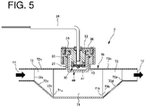
- FIG. 5 is a vertical cross-sectional view of a carbonated water sterilization device 8 according to the third embodiment. A description of portions/regions that do not change from those of the foregoing embodiments is omitted.
- the shapes of a second tube portion 72 and a third tube portion 73 of a main tube portion 70 are different from those of the corresponding portions in the second embodiment.
- the second tube portion 62 and the third tube portion 63 in the second embodiment are truncated conical cylindrical bodies.
- the second tube portion 72 and the third tube portion 73 of the third embodiment are truncated half-conical cylindrical bodies corresponding to half portions obtained by longitudinally cutting the truncated cone from its top surface to its bottom surface.
- one end portion 72a of the second tube portion 72 corresponding to the upper surface of the truncated half-conical cylindrical body is disposed closer to the inlet port 11.
- the other end portion 72b of the second tube portion 72 corresponding to the bottom surface of the truncated half-conical cylindrical body is continuous with one end portion 71a of the first tube portion 71, i.e., the end portion thereof closer to the inlet port 11.
- the second tube portion 72 includes a side wall region 72c on one side (i.e., one side wall region 72c) disposed closer to the light source portion 30 (on the upper side in FIG. 5 ), where the one side wall portion 72c is not inclined, but extends along the axis direction of the main tube portion 70.
- the second tube portion 72 includes a side wall region 72d on the other side (i.e., the other side wall region 72d) facing the one side wall region 72c.
- the other side wall region 72d is inclined so as to increase the distance to the one side wall region 72c as approaching the first tube portion 71.
- the second tube portion 72 with such a structure can increase the flow rate of the carbonated water passing through the second tube portion 72 and reaching the first tube portion 71 as the carbonated water approaches the one side wall region 72c, and can decrease the flow rate thereof as the carbonated water approaches the other side wall region 72d.
- the intensity of the ultraviolet light irradiated from the light source portion 30 to the area closer to the one side wall region 72c becomes stronger (higher) whereas the intensity thereof to the area closer to the other side wall region 72d becomes weaker (lower).
- the carbonated water flowing through the main tube portion 70 can be irradiated with ultraviolet light of high intensity in the region where the flow rate is high, while the carbonated water can be irradiated with ultraviolet light of low intensity in the region where the flow rate is low.
- the carbonated water sterilization device can irradiate the carbonated water with a sufficient amount of ultraviolet light regardless of the distance from the light source portion. As a result, the sterilization efficiency for the carbonated water can be increased.
- the other side wall region 72d in the second tube portion 72 is gradually inclined in a slope shape from one end portion 72a closer to the inlet port 11 toward the other end portion 72b closer to the first tube portion 71.
- This configuration can allow the carbonated water to flow through the second tube portion 72 without greatly changing the traveling direction. As a result, the pressure loss of the carbonated water flowing through the second tube portion 72 is suppressed, and carbon dioxide gas in the carbonated water can thus be prevented from being released from the carbonated water.
- one end portion 73a of the third tube portion 73 corresponding to the upper surface of the truncated half-conical cylindrical body is disposed closer to the outlet port 12.
- the other end portion 73b of the third tube portion 73 corresponding to the bottom surface of the truncated half-conical cylindrical body is continuous with the other end portion 71b of the first tube portion 71, i.e., the end portion closer to the outlet port 12.
- the third tube portion 73 includes one side wall region 73c on one side (i.e., one side wall region 73c) disposed closer to the light source portion 30 (on the upper side in FIG. 5 ), where the one side wall region 73c is not inclined, but extends along the axis direction of the main tube portion 70.
- the third tube portion 73 includes a side wall region 73d on the other side (i.e., the other side wall region 73d) facing the one side wall region 73c.
- the other side wall region 73d is inclined so as to decrease the distance to the one side wall region 73c, as it is distanced from the first tube portion 71.
- the other side wall region 73d in the third tube portion 73 is gradually inclined in a slope shape from the other end portion 73b closer to the first tube portion 71 toward the one end portion 73a closer to the outlet port 12.
- This configuration can allow the carbonated water to flow through the third tube portion 73 without greatly changing the traveling direction.
- the pressure loss of the carbonated water flowing through the third tube portion 73 is suppressed, and carbon dioxide gas in the carbonated water can thus be prevented from being released from the carbonated water.
- the carbonated water sterilization unit includes a plurality of the carbonated water sterilization devices connected in series.
- FIG. 6 is a vertical cross-sectional view of a carbonated water sterilization unit 500 constituted by a plurality of the carbonated water sterilization devices 3 according to the first embodiment.
- FIG. 7 is a vertical cross-sectional view of a carbonated water sterilization unit 600 constituted by a plurality of the carbonated water sterilization devices 7 according to the second embodiment.
- FIG. 8 is a vertical cross-sectional view of a carbonated water sterilization unit 700 constituted by a plurality of the carbonated water sterilization devices 8 according to the third embodiment.
- the carbonated water sterilization unit 500 is configured by connecting the inlet port 11 of one of the carbonated water sterilization devices 3 and the outlet port 12 of the adjacent one of the carbonated water sterilization devices 3 in the adjacent two carbonated water sterilization devices 3 adjacent to each other.
- the plurality of carbonated water sterilization devices 1 connected in series can increase the irradiation amount of ultraviolet light to the carbonated water flowing through the main tube portions 10. As a result, the sterilization efficiency for the carbonated water can be increased.
- the inlet port 11 of one of the carbonated water sterilization devices 7 (8) and the outlet port 12 of the adjacent one of the carbonated water sterilization devices 7 (8) in the two adjacent carbonated water sterilization devices 7 (8) are connected (see FIGS. 7 and 8 ).
- the irradiation amount of ultraviolet light to the carbonated water flowing through the main tube portions 60 (70) can be increased, and as a result, the sterilization efficiency for the carbonated water can be increased.
Abstract
Description
- The present invention relates to a beverage supply device.
- A beverage supply device for supplying a beverage containing carbonated water has been provided (for example,
Japanese Patent No. 6727808 -
Japanese Patent Application Laid-Open No. 2019-018198 - However, the flowing water of the flow-water sterilization module flows into the interior of the flow pipe from a first inlet and outlet portion provided on the side of the flow pipe, and flows out from a second inlet and outlet portion provided above the flow pipe to the outside of the flow pipe. That is, the path of the flowing water in the flow-water sterilization module has a substantially right angle in the flow pipe. Therefore, vortices and turbulence are generated in the flowing water, and thus, the pressure applied to the fluid is reduced, or i.e., a pressure loss occurs. In general, the solubility of carbon dioxide gas decreases as the pressure applied to water decreases. Thus, in a case where the flowing water is carbonated, there is a higher possibility that carbon dioxide gas is released from the carbonated water by the pressure loss.
- Furthermore, the light source in the flow-water sterilization module disclosed in
Japanese Patent Application Laid-Open No. 2019-018198 - In view of the above-described problems, it is an object of the present invention to provide a beverage supply device which can suppress a situation in which carbon dioxide gas is released from carbonated water even when carbonated water is caused to flow through a circulation flow path, and which does not impair the sterilization ability for carbonated water.
- In order to solve the above-described problems, a beverage supply device according to the present invention includes a circulation flow path in which carbonated water is circulated, and a carbonated water sterilization device provided in the circulation flow path, the carbonated water sterilization device including: a main tube portion which includes an inlet port for carbonated water provided on one side of both ends which are opposite to each other in an axis direction of the main tube portion, and an outlet port for the carbonated water provided on the other side; a light source portion configured to irradiate the carbonated water flowing through the main tube portion with ultraviolet light; and a cap portion which has an ability to transmit ultraviolet light, the cap portion being configured to separate the light source portion and the main tube portion.
- In the fluid sterilization device according to this aspect of the present invention, the inlet port for the carbonated water is located on one side of the ends of the main tube portion which are opposite to each other in the axis direction thereof, and the outlet port for the carbonated water is located on the other side. Therefore, this configuration can allow the carbonated water to flow through the main tube portion without the traveling direction of the carbonated water varying greatly across both ends of the main tube portion. As a result, pressure loss of carbonated water traveling through the main tube portion and generation of bubbles can be greatly reduced. As a result, a situation in which carbon dioxide gas is released from carbonated water is suppressed, and the sterilization ability for carbonated water is unimpaired.
- The beverage supply device according to the present invention may preferably further include a communication tube portion connected to a side wall of the main tube portion so as to communicate with the inside of the main tube portion. The light source portion is preferably accommodated in the communication tube portion so as to face the inside of the main tube portion. The cap portion preferably has a distal end wall that faces the light source portion. The distal end wall is preferably disposed along the side wall connected to the communication tube portion, or is preferably disposed inside the main tube portion from the side wall.
- According to this aspect of the present invention, the distal end wall of the cap portion that separates the light source portion and the main tube portion in the communication tube portion (wall portion that faces the light source portion) may be disposed, along the side wall of the main tube portion which is connected to the communication tube portion, or inside the main tube portion from the side wall. Therefore, concave spaces, into which the carbonated water and bubbles flowing through the main tube portion may flow, do not form in the boundary portion between the light source portion and the main tube portion (the foregoing distal end wall). Thus, stagnant layers and bubbles are less likely to be generated in the boundary portion between the light source portion and the main tube portion.
- Furthermore, in the beverage supply device according to the present invention, the main tube portion preferably includes a first tube portion including a communication region which is linked to the communication tube portion, and a second tube portion connected to an end of the first tube portion on a side closer to the inlet port. In this configuration, the second tube portion preferably has a diameter that increases from the side closer to the inlet port toward the first tube portion.
- In this aspect of the present invention, the second tube portion expands in diameter as it approaches the first tube portion from the inlet port side. Increasing the diameter of the second tube portion in this manner can reduce the flow rate of the carbonated water passing through the second tube portion as the carbonated water approaches the first tube portion. At this time, the first tube portion is connected to the communication tube portion that accommodates the light source portion. Therefore, the beverage sterilization device according to this aspect of the present invention can reduce the flow rate of the carbonated water that flows in the vicinity of the light source portion, and also can increase the amount of irradiated ultraviolet light. As a result, the beverage sterilization device can increase the sterilization efficiency.
- Furthermore, the beverage supply device according to the present invention is configured so that, in a vertical cross-sectional view of the second tube portion, the second tube portion preferably includes a side wall region on one side disposed closer to the light source portion, the side wall region on the one side extending along the axis direction of the main tube portion, and a side wall region on the other side, which faces the side wall region on the one side, the side wall region on the other side being inclined, in the direction approaching the first tube portion from the inlet port side, so as to increase the distance to the side wall region on the one side.
- The beverage supply device according to this aspect of the present invention can control the flow rate of the carbonated water passing through the second tube portion to the first tube portion so that the flow rate thereof is greater as the carbonated water is closer to the side wall region on the one side (the side wall region disposed close to the light source portion) and lower as the carbonated water is closer to the side wall region on the other side (the side wall region facing the side wall region on the one side). At this time, the intensity of the ultraviolet light irradiated from the light source portion becomes stronger toward the side wall region on the one side, and weaker toward the side wall region on the other side. Therefore, the beverage supply device according to this aspect of the present invention can irradiate the carbonated water flowing through the main tube portion with ultraviolet light in high intensity in the region where the flow rate is great, while irradiating the carbonated water with ultraviolet light in low intensity in the region where the flow rate is low. Thus, the beverage supply device can irradiate the carbonated water with a sufficient amount of ultraviolet light regardless of the distance from the light source portion. As a result, the sterilization efficiency for the carbonated water can be increased.
- Furthermore, the beverage supply device according to the present invention includes a plurality of carbonated water sterilization devices with the foregoing configuration connected with one another, which serves as a carbonated water sterilization unit. In two such adjacent carbonated water sterilization devices, an inlet port of one of the two adjacent carbonated water sterilization devices and an outlet port of the other of the two adjacent carbonated water sterilization devices are connected to each other.
- In the beverage supply device according to the present invention, the plurality of carbonated water sterilization devices can be linked so that the inlet port of one of two adjacent carbonated water sterilization devices and the outlet port of the other one of the two adjacent carbonated water sterilization devices are connected to each other. Therefore, the carbonated water can be irradiated with a sufficient amount of ultraviolet light. As a result, the sterilization efficiency for the carbonated water can be increased.
- According to the present invention, a beverage supply device may be provided which can suppress a situation in which carbon dioxide gas is released from carbonated water even when carbonated water is caused to flow through a circulation flow path, and which does not impair the sterilization ability for carbonated water.
- These and other characteristics, features, and advantages of the presently disclosed subject matter will become clear from the following description with reference to the accompanying drawings, wherein:
-
FIG. 1 is a schematic configuration diagram of a beverage supply device according to an embodiment of the present invention. -
FIGS. 2(a), 2(b), and 2(c) are a plan view of a carbonated water sterilization device according to a first embodiment, a side view thereof, and a vertical cross-sectional view thereof, respectively. -
FIG. 3 is a vertical cross-sectional view illustrating a communication tube portion communicating with a main tube portion of the carbonated water sterilization device according to the first embodiment, and a light source portion accommodated in the communication tube portion. -
FIG. 4 is a vertical cross-sectional view of the carbonated water sterilization device according to a second embodiment. -
FIG. 5 is a vertical cross-sectional view of the carbonated water sterilization device according to a third embodiment. -
FIG. 6 is a vertical cross-sectional view of a carbonated water sterilization unit. -
FIG. 7 is a vertical cross-sectional view of another carbonated water sterilization unit. -
FIG. 8 is a vertical cross-sectional view of another carbonated water sterilization unit. - First, with reference to
FIG. 1 , a beverage supply device according to an embodiment of the present invention will be described in detail.FIG. 1 is a schematic configuration diagram of abeverage supply device 1 according to an embodiment of the present invention. Thebeverage supply device 1 illustrated inFIG.1 is usable as a drink server or a vending machine, and includes acirculation flow path 2 in which carbonated water is circulated, and a carbonatedwater sterilization device 3 provided in thecirculation flow path 2. - The
beverage supply device 1 further includes acarbonation tank 4 and a raw-water flow pipe 5 for circulating raw water (e.g., water supplied from tap water). Oneend 5a of the raw-water flow pipe 5 is located in thecarbonation tank 4. Carbonated water is generated by adding carbon dioxide gas to raw water supplied to thecarbonation tank 4 through the raw-water flow pipe 5. As illustrated inFIG. 1 , thecarbonation tank 4 is preferably accommodated in acooling tank 4h. - Furthermore, one
end 2a of thecirculation flow path 2 is located in thecarbonation tank 4. Thecirculation flow path 2 is provided with apump device 6. When thepump device 6 is driven, carbonated water is supplied from thecarbonation tank 4 to thecirculation flow path 2. The carbonated water supplied to thecirculation flow path 2 passes through the carbonatedwater sterilization device 3. During the passage of the carbonated water through the carbonatedwater sterilization device 3, the carbonated water is irradiated with ultraviolet light, so that the carbonated water is sterilized. Subsequently, the carbonated water that has passed through the carbonatedwater sterilization device 3 returns to the upstream side of thepump device 6 through thecirculation flow path 2. Thus, thecirculation flow path 2 is provided to the carbonatedwater sterilization device 3, and the circulated carbonated water through thecirculation flow path 2 can be repeatedly irradiated with ultraviolet light. In this manner, the sterilization efficiency to the circulated carbonated water can be improved. - The
beverage supply device 1 has adischarge port 2e for the carbonated water flowing through thecirculation flow path 2. Thedischarge port 2e is located downstream of an outlet port of the carbonated water sterilization device 3 (an outlet port of a main tube portion, which will be described later). When thedischarge port 2e is open, the carbonated water flowing from the carbonatedwater sterilization device 3 is discharged to the outside of thecirculation flow path 2 through thedischarge port 2e. Note that thebeverage supply device 1 may include a storage tank or a flow path for other raw materials, such as a syrup, fruit juice, or the like. - A description will now be given below on the carbonated
water sterilization device 3 according to the first embodiment of the present invention in detail with reference toFIGS. 2 and3 .FIG. 2A is a plan view of the carbonatedwater sterilization device 3,FIG. 2B is a side view thereof, andFIG. 2C is a vertical cross-sectional view thereof - a cross-sectional view taken along line A-A of FIG. IB.FIG. 3 is a vertical cross-sectional view illustrating acommunication tube portion 20 that communicates with amain tube portion 10 of the carbonatedwater sterilization device 3, and alight source portion 30 that is accommodated in thecommunication tube portion 20. - For example, as illustrated in
FIG. 2C , the carbonatedwater sterilization device 3 according to the present embodiment includes themain tube portion 10 through which carbonated water flows, thecommunication tube portion 20 that communicates with the inside of themain tube portion 10 by connecting it with aside wall 10S of the main tube portion 10 (a side wall 10S1 inFIG. 2C ), thelight source portion 30 that is accommodated in thecommunication tube portion 20, and acap portion 40 that separates thelight source portion 30 and themain tube portion 10. - The
main tube portion 10 in the present embodiment is a long cylindrical body, but is not limited thereto. The form of themain tube portion 10 may be, for example, a long prismatic cylinder or the like. Furthermore, themain tube portion 10 in the present embodiment is made of stainless steel, but is not limited thereto. Examples of the material of themain tube portion 10 may include a metal other than stainless steel and a resin such as tetrafluoroethylene (PTFE). As described later, themain tube portion 10 in the present embodiment is in thermal contact with thelight source portion 30 via thecommunication tube portion 20 and aframe body 50, which will be described later, both made of metal. Therefore, the metallicmain tube portion 10 can efficiently dissipate heat transferred from thelight source portion 30 to the outside of themain tube portion 10, thereby effectively cooling thelight source portion 30. - An
inlet port 11 is provided at one of two opposite ends in the axis direction of the main tube portion 10 (long axis direction). Anoutlet port 12 is provided at the other end. Carbonated water to be sterilized flows into themain tube portion 10 from theinlet port 11, flows through themain tube portion 10, and then flows out of themain tube portion 10 through theoutlet port 12. Thelight source portion 30 is accommodated in thecommunication tube portion 20 from the upper side thereof as viewed inFIG. 2C so as to be located in the inside of the main tube portion 10 (i.e., the carbonated water flowing through the main tube portion 10), and thus, the carbonated water is irradiated with ultraviolet light from thelight source portion 30. This causes the carbonated water to be sterilized. Furthermore, thelight source portion 30 is preferably located above themain tube portion 10. The reason thereof will be discussed later. - As illustrated in
FIGS. 2A to 2C , the carbonated water flowing through themain tube portion 10 flows substantially linearly from theinlet port 11 to theoutlet port 12 which are opposite to each other in the axis direction. That is, the carbonated water flowing through themain tube portion 10 flows without the traveling direction varying greatly. Therefore, thebeverage supply device 1 can suppress the pressure loss of carbonated water in themain tube portion 10, so that carbon dioxide gas in the carbonated water is prevented from being released during the flow through themain tube portion 10. - The
communication tube portion 20 in the present embodiment is a cylindrical body that extends radially outward from themain tube portion 10, more specifically, from the peripheral edge of a throughhole 13 provided in the side wall 10S1 of themain tube portion 10. Furthermore, the inside of themain tube portion 10 and the inside of thecommunication tube portion 20 communicate with each other through the throughhole 13. - The
communication tube portion 20 may be made of metal such as stainless steel or aluminum, or may be made of a resin such as PTFE. As described later, it is preferable for thecommunication tube portion 20 to be made of metal capable of efficiently dissipating heat transferred from thelight source portion 30 to themain tube portion 10, since thecommunication tube portion 20 serves as a member which is in thermal contact with thelight source portion 30. - The
light source portion 30 is accommodated in thecommunication tube portion 20. Thelight source portion 30 is insulated with thecap portion 40. Thus, thecap portion 40 separates themain tube portion 10 and thelight source portion 30, and as a result, the carbonated water flowing through themain tube portion 10 enters thecommunication tube portion 20, thereby avoiding a situation where the carbonated water comes into contact with thelight source portion 30. Hereinafter, thecommunication tube portion 20, thelight source portion 30, and thecap portion 40 will be described in detail with reference toFIG. 3 . - As illustrated in
FIG. 3 , thelight source portion 30 includes alight emitting element 31 capable of irradiating ultraviolet light, asubstrate 32 for mounting thelight emitting element 31, and aheat sink 33 for mounting thesubstrate 32 and for dissipating heat transferred from thelight emitting element 31 through thesubstrate 32. Thelight emitting element 31 is mounted on the surface of thesubstrate 32 opposed to themain tube portion 10 so as to face the carbonated water flowing through themain tube portion 10. Thelight emitting element 31 is electrically connected to apower supply cable 34 via thesubstrate 32. - The type of the
light emitting element 31 is not particularly limited, and for example, a semiconductor light emitting element such as a light emitting diode (LED) or a laser diode may be used. In thelight source portion 30 illustrated inFIG. 3 , the number oflight emitting elements 31 mounted on thesubstrate 32 is one, but may be two or more. - The
light source portion 30 in the present embodiment is supported by theframe body 50 which has a substantially cylindrical shape. Theframe body 50 for supporting thelight source portion 30 is mounted to thecommunication tube portion 20 so as to be detachable. More specifically, theframe body 50 includes an upper end portion orupper surface 52, and a lower end portion having amale screw groove 53. When thelight source portion 30 is inserted into a hollow area formed in the center of theframe body 50, aflange surface 35 of theheat sink 33 is placed upon theupper surface 52 of theframe body 50. Thereafter, theflange surface 35 is screwed to theupper surface 52 of theframe body 50. As illustrated inFIG. 3 , the screwedflange surface 35 may be covered with ametal lid 36. - Furthermore, the
male screw groove 53 is formed at the lower end of theframe body 50, and afemale screw groove 21 screwed into themale screw groove 53 is formed at the upper end of the outer surface of thecommunication tube portion 20. After the lower end of theframe body 50 and the upper end of thecommunication tube portion 20 are in contact with each other, theframe body 50 is rotated, so that themale screw groove 53 and thefemale screw groove 21 are engaged with each other. As a result, theframe body 50 is screwed to thecommunication tube portion 20, and thus, thelight source portion 30 is accommodated in thecommunication tube portion 20. - The
light source portion 30 is detachably provided in thecommunication tube portion 20 via theframe body 50 so that thelight source portion 30 is thermally in contact with the communication tube portion via theframe body 50. Thus, it is possible for the replacement operation of the existinglight source portion 30 with another newlight source portion 30 to be performed easily. Furthermore, this configuration can promote the heat dissipation efficiency by the thermally connectedheat sink 33,frame body 50 and associated portions. The replacement operation of thelight source portion 30 in the present embodiment is to mount theframe body 50, onto which thelight source portion 30 has been attached, to thecommunication tube portion 20 that extends outward from the straight tubularmain tube portion 10. Therefore, when theframe body 50 is mounted to thecommunication tube portion 20, there is no component that interferes with the operator's hand, thus making it possible to perform the replacement operation of thelight source portion 30 without stress and quickly. - Furthermore, as illustrated in
FIG. 3 , atriangular groove 54 is formed at the upper end of theframe body 50. An O-ring 55 for sealing a joint portion between thelight source portion 30 and theframe body 50 is fitted to thetriangular groove 54. Similarly, atriangular groove 22 is formed at the upper end of the inner surface of thecommunication tube portion 20. In thetriangular groove 22, an O-ring 23 for sealing a joint portion between thecommunication tube portion 20 and thecap portion 40 and a joint portion between thecommunication tube portion 20 and theframe body 50 is fitted. - The material for the
frame body 50 is not particularly limited, and in order to efficiently dissipate heat transferred from theheat sink 33 of thelight source portion 30 to thecommunication tube portion 20, the frame body is preferably made of metal. Thus, similar to theframe body 50, themain tube portion 10 and thecommunication tube portion 20 are made of metal, so that it is possible to efficiently transmit heat from theheat sink 33 to the carbonated water flowing through themain tube portion 10. As a result, it is possible to effectively cool thelight source portion 30. - The
cap portion 40 is made of a material that has an ability to transmit ultraviolet light such as quartz, perfluoroalkoxyalkane (PFA), or a perfluoroethylene propene copolymer (FEP), and is a member which is fitted into a hollow region inside thecommunication tube portion 20 so as to cover thelight source portion 30. Thecap portion 40 in the present embodiment is a cylindrical body with an opening at one end, and includes adistal end wall 41 facing thelight emitting element 31 of thelight source portion 30, and a sideperipheral wall 42 extending, substantially, perpendicularly continuous with the peripheral edge of thedistal end wall 41. - In the present invention, it is preferable to prevent pressure loss of the carbonated water flowing through the
main tube portion 10. To cope with this, in the present embodiment themain tube portion 10 is preferably formed in a linear shape in order to prevent any disturbance against the flow of the carbonated water through themain tube portion 10. Furthermore, the ultraviolet light is irradiated from a direction orthogonal to the direction along which the linearmain tube portion 10 extends. - The
distal end wall 41 is configured to be parallel to the flowing direction of the carbonated water through themain tube portion 10 as illustrated inFIG. 2 and to have a length in the flowing direction equal to or less than the inner diameter of themain tube portion 10. Since the area of thedistal end wall 41 is designed with the length equal to or smaller than the inner diameter of themain tube portion 10, even when the internal pressure inside thecirculation flow path 2 may increase due to carbon dioxide gas released from the carbonated water flowing through thecirculation flow path 2, any possibility in which thedistal end wall 41 is broken by the pressure increase can be reduced. - The side
peripheral wall 42 is located between the inner wall of thecommunication tube portion 20 and theheat sink 33. Thedistal end wall 41 in the present embodiment is a plane wall substantially parallel to the side wall 10S1 of themain tube portion 10. However, the shape of thedistal end wall 41 is not limited to this, and another form of thedistal end wall 41 may be a curved wall curving inward (protruding) toward the inside of themain tube portion 10 such as a hemisphere or semi-elliptical sphere. - A
distal end wall 41 of thecap portion 40 is disposed inside themain tube portion 10 from the side wall 10S1. For example, in the case of the mode illustrated inFIG. 2C , thedistal end wall 41 of thecap portion 40 is disposed inside themain tube portion 10 by a distance L from the side wall 10S1. Thedistal end wall 41 of thecap portion 40 and the side wall 10S1 with such a positional relationship can prevent the formation of a concave space, in which the carbonated water and bubbles flowing through themain tube portion 10 would flow into, in the boundary portion between thelight source portion 30 and the main tube portion 10 (distal end wall 41). Furthermore, when cooled carbonated water is caused to flow the passage, condensed dew may be deposited inside thelight source portion 30 and at surrounding area. However, thelight source portion 30 and the associated components are disposed above themain tube portion 10 and directed downward, specifically, thelight source portion 30 is located above themain tube portion 10 and thecap portion 40 is located below thelight source portion 30. Thus, even if there is condensed dew inside the area, such dew may not affect thelight source portion 30 directly and may not cause any electrical failure. If this structure is inverse, dew may drop onto the electrical components directly, causing electrical failure. The present invention can however prevent such failure with the specific structure. - This configuration can also prevent the generation of a stagnant layer and bubbles in the boundary portion between the
light source portion 30 and themain tube portion 10. As a result, the carbonated water can smoothly flow through themain tube portion 10, and carbon dioxide gas is prevented from being released from the carbonated water. Furthermore, ultraviolet light, which is irradiated from thelight source portion 30 onto the carbonated water, can be prevented from being blocked by air bubbles, and thus, it is possible to effectively prevent a situation in which the sterilization efficiency for the carbonated water is reduced due to such bubbles. - Herein, the positional relationship between the
distal end wall 41 and the side wall 10S1 is not limited to the foregoing structure. For example, thedistal end wall 41 may be disposed along the side wall 10S1, i.e., the distance L between thedistal end wall 41 and the side wall 10S1 described above is zero (0). Thus, thedistal end wall 41 and the side wall 10S1 may be disposed at a substantially identical height position. Even with thedistal end wall 41 and the side wall 10S1 being at such a positional relationship, a concave space is not formed in the boundary portion between thelight source portion 30 and the main tube portion 10 (at the distal end wall 41). As a result, it is possible to suppress a situation in which a stagnant layer is generated or bubbles remain in the vicinity of the boundary portion, i.e., thedistal end wall 41. - Next, a second embodiment of the beverage supply device including the carbonated water sterilization device according to the present invention will be described with reference to
FIG. 4. FIG. 4 is a vertical cross-sectional view of a carbonated water sterilization device 7 according to the second embodiment. A description of portions/regions that do not change from those of the first embodiment is omitted. - A portion different in the second embodiment from the first embodiment described above is the form of the
main tube portion 60. Themain tube portion 10 in the first embodiment is a straight tubular cylindrical body having no inclined portion with substantially the same diameter from theinlet port 11 toward theoutlet port 12. In contrast, themain tube portion 60 in the second embodiment, as illustrated inFIG. 4 , includes a straight tubularfirst tube portion 61 located in the center in the axis direction of themain tube portion 60, a frustoconicalsecond tube portion 62 which is disposed on theinlet port 11 side closer than thefirst tube portion 61, thesecond tube portion 62 expanding in diameter as approaching thefirst tube portion 61, and athird tube portion 63 which is disposed on theoutlet port 12 side closer than thefirst tube portion 61, thethird tube portion 63 decreasing in diameter as distanced away from thefirst tube portion 61. - The
first tube portion 61 is connected to thecommunication tube portion 20, so that both interior spaces are communicated with each other. Thesecond tube portion 62 is continuous with oneend portion 61a of the first tube portion 61 (the end portion closer to the inlet port 11). Thethird tube portion 63 is continuous with theother end portion 61b of the first tube portion 61 (the end portion closer to the outlet port 12). - According to the second embodiment, the diameter of the
second tube portion 62 increases as it approaches thefirst tube portion 61. Therefore, the flow rate of the carbonated water flowing into themain tube portion 60 from theinlet port 11 can be reduced as it approaches thefirst tube portion 61. Thus, this configuration can slow the flow rate of the carbonated water in the vicinity of thelight source portion 30 facing the inside of thefirst tube portion 61, so that the carbonated water can be irradiated with ultraviolet light in an increased amount of light. As a result, the sterilization efficiency for the carbonated water can be increased. - As illustrated in
FIG. 4 , thesecond tube portion 62 is gradually increased in diameter in a slope shape from oneend portion 62a closer to theinlet port 11 toward theother end portion 62b closer to thefirst tube portion 61. This configuration can allow the carbonated water to flow through thesecond tube portion 62 without greatly changing the traveling direction. As a result, the pressure loss of the carbonated water flowing through thesecond tube portion 62 is suppressed, and carbon dioxide gas in the carbonated water can thus be prevented from being released from the carbonated water. - In contrast, the
third tube portion 63 is a frustoconical cylindrical body having a reduced diameter as approaching theoutlet port 12 from thefirst tube portion 61. As illustrated inFIG. 4 , thethird tube portion 63 is gradually reduced in diameter in a slope shape from oneend portion 63a closer to thefirst tube portion 61 to theother end portion 63b closer to theoutlet port 12. This configuration can allow the carbonated water to flow through thethird tube portion 63 without greatly changing the traveling direction. As a result, the pressure loss of the carbonated water flowing through thethird tube portion 63 is suppressed, and carbon dioxide gas in the carbonated water can thus be prevented from being released from the carbonated water. - Next, a third embodiment of the beverage supply device including a carbonated water sterilization device according to the present invention will be described with reference to
FIG. 5. FIG. 5 is a vertical cross-sectional view of a carbonatedwater sterilization device 8 according to the third embodiment. A description of portions/regions that do not change from those of the foregoing embodiments is omitted. - In the third embodiment, the shapes of a
second tube portion 72 and athird tube portion 73 of amain tube portion 70 are different from those of the corresponding portions in the second embodiment. As described above, thesecond tube portion 62 and thethird tube portion 63 in the second embodiment are truncated conical cylindrical bodies. On the other hand, thesecond tube portion 72 and thethird tube portion 73 of the third embodiment are truncated half-conical cylindrical bodies corresponding to half portions obtained by longitudinally cutting the truncated cone from its top surface to its bottom surface. - More specifically, one
end portion 72a of thesecond tube portion 72 corresponding to the upper surface of the truncated half-conical cylindrical body is disposed closer to theinlet port 11. Theother end portion 72b of thesecond tube portion 72 corresponding to the bottom surface of the truncated half-conical cylindrical body is continuous with oneend portion 71a of thefirst tube portion 71, i.e., the end portion thereof closer to theinlet port 11. - Thus, in the vertical cross-sectional view of the second tube portion 72 (see
FIG. 5 ), thesecond tube portion 72 includes aside wall region 72c on one side (i.e., oneside wall region 72c) disposed closer to the light source portion 30 (on the upper side inFIG. 5 ), where the oneside wall portion 72c is not inclined, but extends along the axis direction of themain tube portion 70. In contrast, in a vertical cross-sectional view of the second tube portion 72 (seeFIG. 5 ), thesecond tube portion 72 includes aside wall region 72d on the other side (i.e., the otherside wall region 72d) facing the oneside wall region 72c. The otherside wall region 72d is inclined so as to increase the distance to the oneside wall region 72c as approaching thefirst tube portion 71. - The
second tube portion 72 with such a structure can increase the flow rate of the carbonated water passing through thesecond tube portion 72 and reaching thefirst tube portion 71 as the carbonated water approaches the oneside wall region 72c, and can decrease the flow rate thereof as the carbonated water approaches the otherside wall region 72d. In this configuration, the intensity of the ultraviolet light irradiated from thelight source portion 30 to the area closer to the oneside wall region 72c becomes stronger (higher) whereas the intensity thereof to the area closer to the otherside wall region 72d becomes weaker (lower). Therefore, according to the third embodiment, the carbonated water flowing through themain tube portion 70 can be irradiated with ultraviolet light of high intensity in the region where the flow rate is high, while the carbonated water can be irradiated with ultraviolet light of low intensity in the region where the flow rate is low. Thus, the carbonated water sterilization device can irradiate the carbonated water with a sufficient amount of ultraviolet light regardless of the distance from the light source portion. As a result, the sterilization efficiency for the carbonated water can be increased. - The other
side wall region 72d in thesecond tube portion 72 is gradually inclined in a slope shape from oneend portion 72a closer to theinlet port 11 toward theother end portion 72b closer to thefirst tube portion 71. This configuration can allow the carbonated water to flow through thesecond tube portion 72 without greatly changing the traveling direction. As a result, the pressure loss of the carbonated water flowing through thesecond tube portion 72 is suppressed, and carbon dioxide gas in the carbonated water can thus be prevented from being released from the carbonated water. - Furthermore, in the
third tube portion 73, oneend portion 73a of thethird tube portion 73 corresponding to the upper surface of the truncated half-conical cylindrical body is disposed closer to theoutlet port 12. Theother end portion 73b of thethird tube portion 73 corresponding to the bottom surface of the truncated half-conical cylindrical body is continuous with theother end portion 71b of thefirst tube portion 71, i.e., the end portion closer to theoutlet port 12. - Thus, in the vertical cross-sectional view of the third tube portion 73 (see
FIG. 5 ), thethird tube portion 73 includes oneside wall region 73c on one side (i.e., oneside wall region 73c) disposed closer to the light source portion 30 (on the upper side inFIG. 5 ), where the oneside wall region 73c is not inclined, but extends along the axis direction of themain tube portion 70. In contrast, in the vertical cross-sectional view of the third tube portion 73 (seeFIG. 5 ), thethird tube portion 73 includes aside wall region 73d on the other side (i.e., the otherside wall region 73d) facing the oneside wall region 73c. The otherside wall region 73d is inclined so as to decrease the distance to the oneside wall region 73c, as it is distanced from thefirst tube portion 71. - Thus, the other
side wall region 73d in thethird tube portion 73 is gradually inclined in a slope shape from theother end portion 73b closer to thefirst tube portion 71 toward the oneend portion 73a closer to theoutlet port 12. This configuration can allow the carbonated water to flow through thethird tube portion 73 without greatly changing the traveling direction. As a result, the pressure loss of the carbonated water flowing through thethird tube portion 73 is suppressed, and carbon dioxide gas in the carbonated water can thus be prevented from being released from the carbonated water. - Next, a carbonated water sterilization unit included in the beverage supply device according to the present invention will be described with reference to
FIGS. 6 to 8 . The carbonated water sterilization unit includes a plurality of the carbonated water sterilization devices connected in series.FIG. 6 is a vertical cross-sectional view of a carbonatedwater sterilization unit 500 constituted by a plurality of the carbonatedwater sterilization devices 3 according to the first embodiment.FIG. 7 is a vertical cross-sectional view of a carbonatedwater sterilization unit 600 constituted by a plurality of the carbonated water sterilization devices 7 according to the second embodiment.FIG. 8 is a vertical cross-sectional view of a carbonatedwater sterilization unit 700 constituted by a plurality of the carbonatedwater sterilization devices 8 according to the third embodiment. - As illustrated in
FIG. 6 , the carbonatedwater sterilization unit 500 is configured by connecting theinlet port 11 of one of the carbonatedwater sterilization devices 3 and theoutlet port 12 of the adjacent one of the carbonatedwater sterilization devices 3 in the adjacent two carbonatedwater sterilization devices 3 adjacent to each other. In this manner, the plurality of carbonatedwater sterilization devices 1 connected in series can increase the irradiation amount of ultraviolet light to the carbonated water flowing through themain tube portions 10. As a result, the sterilization efficiency for the carbonated water can be increased. - Similarly, in the carbonated water sterilization unit 600 (and also 700), the
inlet port 11 of one of the carbonated water sterilization devices 7 (8) and theoutlet port 12 of the adjacent one of the carbonated water sterilization devices 7 (8) in the two adjacent carbonated water sterilization devices 7 (8) are connected (seeFIGS. 7 and8 ). As in the case of the carbonatedwater sterilization unit 500, the irradiation amount of ultraviolet light to the carbonated water flowing through the main tube portions 60 (70) can be increased, and as a result, the sterilization efficiency for the carbonated water can be increased.
Claims (5)
- A beverage supply device (1) characterized by comprising:a circulation flow path (2) in which carbonated water is circulated; anda carbonated water sterilization device (3, 7, 8) provided in the circulation flow path (2),the carbonated water sterilization device (3, 7, 8) including:a main tube portion (10, 60, 70) which includes an inlet port (11) for carbonated water provided on one side of both ends which are opposite to each other in an axis direction of the main tube portion (10, 60, 70), and an outlet port (12) for the carbonated water provided on the other side;a light source portion (30) configured to irradiate the carbonated water flowing through the main tube portion (10, 60, 70) with ultraviolet light; anda cap portion (40) which has an ability to transmit ultraviolet light, the cap portion (40) being configured to separate the light source portion (30) and the main tube portion (10, 60, 70).
- The beverage supply device (1) according to claim 1, characterized by further comprising a communication tube portion (20) connected to a side wall (10S, 10S1) of the main tube portion (10, 60, 70) so as to communicate with an inside of the main tube portion (10, 60, 70), whereinthe light source portion (30) is accommodated in the communication tube portion (20) so as to face the inside of the main tube portion (10, 60, 70),the cap portion (40) has a distal end wall (41) that faces the light source portion (30), andthe distal end wall (41) is disposed along the side wall (10S, 10S1) connected to the communication tube portion (20), or is disposed inside the main tube portion (10, 60, 70) from the side wall (10S, 10S1).
- The beverage supply device (1) according to claim 2, characterized in that:the main tube portion (60, 70) includesa first tube portion (61, 71) including a communication region which is communicated with the communication tube portion (20), anda second tube portion (62, 72) connected to an end of the first tube portion (61, 72) on a side closer to the inlet port (11); andthe second tube portion (62, 72) has a diameter that increases from a side closer to the inlet port (11) toward the first tube portion (61, 72).
- The beverage supply device (1) according to claim 3, characterized in thatin a vertical cross-sectional view of the second tube portion (72), the second tube portion (72) includesa side wall region (72c) on one side disposed closer to the light source portion (30), the side wall region (72c) on the one side extending in the axis direction of the main tube portion (70), anda side wall region (72d) on the other side, which faces the side wall region (72c) on the one side, the side wall region (72d) being inclined, in a direction approaching the first tube portion (71) from the inlet port (11) side, so as to increase the distance to the side wall region (72c) on the one side.
- A beverage supply device (1) characterized by comprising:a plurality of the carbonated water sterilization devices (3, 7, 8) according to any one of claims 1 to 4, whereintwo adjacent carbonated water sterilization devices (3, 7, 8) are configured such that an inlet port (11) of one of the two adjacent fluid sterilization devices (3, 7, 8) and an outlet port (12) of the other of the two adjacent fluid sterilization devices (3, 7, 8) are connected to each other.
Applications Claiming Priority (1)
| Application Number | Priority Date | Filing Date | Title |
|---|---|---|---|
| JP2021082908A JP2022176460A (en) | 2021-05-17 | 2021-05-17 | Beverage supply device |
Publications (1)
| Publication Number | Publication Date |
|---|---|
| EP4091985A1 true EP4091985A1 (en) | 2022-11-23 |
Family
ID=81654659
Family Applications (1)
| Application Number | Title | Priority Date | Filing Date |
|---|---|---|---|
| EP22173591.3A Pending EP4091985A1 (en) | 2021-05-17 | 2022-05-16 | Beverage supply device |
Country Status (2)
| Country | Link |
|---|---|
| EP (1) | EP4091985A1 (en) |
| JP (1) | JP2022176460A (en) |
Citations (10)
| Publication number | Priority date | Publication date | Assignee | Title |
|---|---|---|---|---|
| JPH0427808B2 (en) | 1983-06-13 | 1992-05-12 | Nestle Sa | |
| US7270748B1 (en) * | 2004-09-21 | 2007-09-18 | Next Energy Wave, Inc. | Sterilizing water faucet |
| DE202012102921U1 (en) * | 2012-08-03 | 2013-11-05 | Friedhelm Selbach Gmbh | Device for dispensing a liquid food |
| US20150056096A1 (en) * | 2013-08-24 | 2015-02-26 | George Harold Hoover | Self-Cleaning Beverage Nozzle |
| US20160052802A1 (en) * | 2013-05-30 | 2016-02-25 | Nikkiso Co., Ltd. | Water purification apparatus |
| US20160278424A1 (en) * | 2015-03-27 | 2016-09-29 | Rayvio Corporation | System and method for dispensing uv treated materials |
| WO2017119266A1 (en) * | 2016-01-05 | 2017-07-13 | サントリーホールディングス株式会社 | Beverage supply device |
| WO2018047629A1 (en) * | 2016-09-09 | 2018-03-15 | 株式会社日本フォトサイエンス | Ultraviolet irradiation device and method |
| JP2019018198A (en) | 2017-07-11 | 2019-02-07 | 旭化成株式会社 | Flowing water sterilization module |
| WO2021085143A1 (en) * | 2019-10-30 | 2021-05-06 | スタンレー電気株式会社 | Fluid sterilization device |
-
2021
- 2021-05-17 JP JP2021082908A patent/JP2022176460A/en active Pending
-
2022
- 2022-05-16 EP EP22173591.3A patent/EP4091985A1/en active Pending
Patent Citations (10)
| Publication number | Priority date | Publication date | Assignee | Title |
|---|---|---|---|---|
| JPH0427808B2 (en) | 1983-06-13 | 1992-05-12 | Nestle Sa | |
| US7270748B1 (en) * | 2004-09-21 | 2007-09-18 | Next Energy Wave, Inc. | Sterilizing water faucet |
| DE202012102921U1 (en) * | 2012-08-03 | 2013-11-05 | Friedhelm Selbach Gmbh | Device for dispensing a liquid food |
| US20160052802A1 (en) * | 2013-05-30 | 2016-02-25 | Nikkiso Co., Ltd. | Water purification apparatus |
| US20150056096A1 (en) * | 2013-08-24 | 2015-02-26 | George Harold Hoover | Self-Cleaning Beverage Nozzle |
| US20160278424A1 (en) * | 2015-03-27 | 2016-09-29 | Rayvio Corporation | System and method for dispensing uv treated materials |
| WO2017119266A1 (en) * | 2016-01-05 | 2017-07-13 | サントリーホールディングス株式会社 | Beverage supply device |
| WO2018047629A1 (en) * | 2016-09-09 | 2018-03-15 | 株式会社日本フォトサイエンス | Ultraviolet irradiation device and method |
| JP2019018198A (en) | 2017-07-11 | 2019-02-07 | 旭化成株式会社 | Flowing water sterilization module |
| WO2021085143A1 (en) * | 2019-10-30 | 2021-05-06 | スタンレー電気株式会社 | Fluid sterilization device |
Also Published As
| Publication number | Publication date |
|---|---|
| JP2022176460A (en) | 2022-11-30 |
Similar Documents
| Publication | Publication Date | Title |
|---|---|---|
| EP3858390A1 (en) | Fluid sterilization device and fluid sterilization unit | |
| CN107921157B (en) | Sterilization device | |
| EP2915546B1 (en) | Ultraviolet sterilizer and sterilization method | |
| JP6458779B2 (en) | Fluid sterilizer | |
| US10736979B2 (en) | Sterilization device | |
| CN208135922U (en) | Fluid sterilizing unit | |
| JP6189914B2 (en) | Ultraviolet irradiation module cell, ultraviolet irradiation module, and installation method of ultraviolet irradiation module | |
| JP6681314B2 (en) | Water treatment apparatus and water treatment method | |
| US20180228928A1 (en) | Fluid sterilization device and fluid sterilization method | |
| TWI753132B (en) | Fluid sterilization device | |
| JP2018140001A (en) | Fluid sterilizer | |
| EP4091985A1 (en) | Beverage supply device | |
| CN111732157A (en) | Fluid sterilizing device | |
| US20220362419A1 (en) | Fluid sterilization device | |
| CN211141587U (en) | Fluid sterilizing device | |
| CN111001019A (en) | Device and apparatus for disinfecting a fluid | |
| US20210087077A1 (en) | Fluid Sterilizer | |
| JP7381365B2 (en) | water treatment equipment | |
| JP6669910B1 (en) | Water treatment equipment | |
| WO2021250386A1 (en) | Dispensing apparatus | |
| JP2023113016A (en) | Fluid sterilizer | |
| CN114053472A (en) | Fluid sterilizing device | |
| JP2022145097A (en) | Fluid sterilization device | |
| KR20230063625A (en) | Disinfector | |
| JP2023047421A (en) | Fluid sterilizer |
Legal Events
| Date | Code | Title | Description |
|---|---|---|---|
| PUAI | Public reference made under article 153(3) epc to a published international application that has entered the european phase |
Free format text: ORIGINAL CODE: 0009012 |
|
| STAA | Information on the status of an ep patent application or granted ep patent |
Free format text: STATUS: THE APPLICATION HAS BEEN PUBLISHED |
|
| AK | Designated contracting states |
Kind code of ref document: A1 Designated state(s): AL AT BE BG CH CY CZ DE DK EE ES FI FR GB GR HR HU IE IS IT LI LT LU LV MC MK MT NL NO PL PT RO RS SE SI SK SM TR |
|
| STAA | Information on the status of an ep patent application or granted ep patent |
Free format text: STATUS: REQUEST FOR EXAMINATION WAS MADE |
|
| 17P | Request for examination filed |
Effective date: 20230523 |
|
| RBV | Designated contracting states (corrected) |
Designated state(s): AL AT BE BG CH CY CZ DE DK EE ES FI FR GB GR HR HU IE IS IT LI LT LU LV MC MK MT NL NO PL PT RO RS SE SI SK SM TR |