EP4091944A1 - Tank system comprising a frame, a dihydrogen tank and means for attaching the tank to the frame - Google Patents
Tank system comprising a frame, a dihydrogen tank and means for attaching the tank to the frame Download PDFInfo
- Publication number
- EP4091944A1 EP4091944A1 EP22174215.8A EP22174215A EP4091944A1 EP 4091944 A1 EP4091944 A1 EP 4091944A1 EP 22174215 A EP22174215 A EP 22174215A EP 4091944 A1 EP4091944 A1 EP 4091944A1
- Authority
- EP
- European Patent Office
- Prior art keywords
- frame
- articulation
- connecting rod
- outer skin
- tank
- Prior art date
- Legal status (The legal status is an assumption and is not a legal conclusion. Google has not performed a legal analysis and makes no representation as to the accuracy of the status listed.)
- Granted
Links
- UFHFLCQGNIYNRP-UHFFFAOYSA-N Hydrogen Chemical compound [H][H] UFHFLCQGNIYNRP-UHFFFAOYSA-N 0.000 title claims abstract description 12
- 239000003351 stiffener Substances 0.000 claims description 9
- 239000000446 fuel Substances 0.000 description 9
- 239000003570 air Substances 0.000 description 4
- 238000009434 installation Methods 0.000 description 3
- 238000003466 welding Methods 0.000 description 3
- 238000001816 cooling Methods 0.000 description 2
- 238000011084 recovery Methods 0.000 description 2
- 230000006978 adaptation Effects 0.000 description 1
- 239000012080 ambient air Substances 0.000 description 1
- QVGXLLKOCUKJST-UHFFFAOYSA-N atomic oxygen Chemical compound [O] QVGXLLKOCUKJST-UHFFFAOYSA-N 0.000 description 1
- 238000006243 chemical reaction Methods 0.000 description 1
- 239000001257 hydrogen Substances 0.000 description 1
- 229910052739 hydrogen Inorganic materials 0.000 description 1
- 239000012528 membrane Substances 0.000 description 1
- 238000000034 method Methods 0.000 description 1
- 239000007800 oxidant agent Substances 0.000 description 1
- 230000003647 oxidation Effects 0.000 description 1
- 238000007254 oxidation reaction Methods 0.000 description 1
- 230000001590 oxidative effect Effects 0.000 description 1
- 239000001301 oxygen Substances 0.000 description 1
- 229910052760 oxygen Inorganic materials 0.000 description 1
- 125000006850 spacer group Chemical group 0.000 description 1
Images


Classifications
-
- B—PERFORMING OPERATIONS; TRANSPORTING
- B64—AIRCRAFT; AVIATION; COSMONAUTICS
- B64D—EQUIPMENT FOR FITTING IN OR TO AIRCRAFT; FLIGHT SUITS; PARACHUTES; ARRANGEMENTS OR MOUNTING OF POWER PLANTS OR PROPULSION TRANSMISSIONS IN AIRCRAFT
- B64D37/00—Arrangements in connection with fuel supply for power plant
- B64D37/02—Tanks
- B64D37/04—Arrangement thereof in or on aircraft
-
- B—PERFORMING OPERATIONS; TRANSPORTING
- B64—AIRCRAFT; AVIATION; COSMONAUTICS
- B64D—EQUIPMENT FOR FITTING IN OR TO AIRCRAFT; FLIGHT SUITS; PARACHUTES; ARRANGEMENTS OR MOUNTING OF POWER PLANTS OR PROPULSION TRANSMISSIONS IN AIRCRAFT
- B64D37/00—Arrangements in connection with fuel supply for power plant
- B64D37/02—Tanks
- B64D37/06—Constructional adaptations thereof
-
- B—PERFORMING OPERATIONS; TRANSPORTING
- B64—AIRCRAFT; AVIATION; COSMONAUTICS
- B64D—EQUIPMENT FOR FITTING IN OR TO AIRCRAFT; FLIGHT SUITS; PARACHUTES; ARRANGEMENTS OR MOUNTING OF POWER PLANTS OR PROPULSION TRANSMISSIONS IN AIRCRAFT
- B64D37/00—Arrangements in connection with fuel supply for power plant
- B64D37/30—Fuel systems for specific fuels
-
- B—PERFORMING OPERATIONS; TRANSPORTING
- B60—VEHICLES IN GENERAL
- B60K—ARRANGEMENT OR MOUNTING OF PROPULSION UNITS OR OF TRANSMISSIONS IN VEHICLES; ARRANGEMENT OR MOUNTING OF PLURAL DIVERSE PRIME-MOVERS IN VEHICLES; AUXILIARY DRIVES FOR VEHICLES; INSTRUMENTATION OR DASHBOARDS FOR VEHICLES; ARRANGEMENTS IN CONNECTION WITH COOLING, AIR INTAKE, GAS EXHAUST OR FUEL SUPPLY OF PROPULSION UNITS IN VEHICLES
- B60K1/00—Arrangement or mounting of electrical propulsion units
- B60K1/04—Arrangement or mounting of electrical propulsion units of the electric storage means for propulsion
-
- B—PERFORMING OPERATIONS; TRANSPORTING
- B60—VEHICLES IN GENERAL
- B60K—ARRANGEMENT OR MOUNTING OF PROPULSION UNITS OR OF TRANSMISSIONS IN VEHICLES; ARRANGEMENT OR MOUNTING OF PLURAL DIVERSE PRIME-MOVERS IN VEHICLES; AUXILIARY DRIVES FOR VEHICLES; INSTRUMENTATION OR DASHBOARDS FOR VEHICLES; ARRANGEMENTS IN CONNECTION WITH COOLING, AIR INTAKE, GAS EXHAUST OR FUEL SUPPLY OF PROPULSION UNITS IN VEHICLES
- B60K15/00—Arrangement in connection with fuel supply of combustion engines or other fuel consuming energy converters, e.g. fuel cells; Mounting or construction of fuel tanks
- B60K15/03—Fuel tanks
- B60K15/063—Arrangement of tanks
- B60K15/067—Mounting of tanks
- B60K15/07—Mounting of tanks of gas tanks
-
- B—PERFORMING OPERATIONS; TRANSPORTING
- B60—VEHICLES IN GENERAL
- B60K—ARRANGEMENT OR MOUNTING OF PROPULSION UNITS OR OF TRANSMISSIONS IN VEHICLES; ARRANGEMENT OR MOUNTING OF PLURAL DIVERSE PRIME-MOVERS IN VEHICLES; AUXILIARY DRIVES FOR VEHICLES; INSTRUMENTATION OR DASHBOARDS FOR VEHICLES; ARRANGEMENTS IN CONNECTION WITH COOLING, AIR INTAKE, GAS EXHAUST OR FUEL SUPPLY OF PROPULSION UNITS IN VEHICLES
- B60K15/00—Arrangement in connection with fuel supply of combustion engines or other fuel consuming energy converters, e.g. fuel cells; Mounting or construction of fuel tanks
- B60K15/03—Fuel tanks
- B60K2015/03309—Tanks specially adapted for particular fuels
- B60K2015/03315—Tanks specially adapted for particular fuels for hydrogen
-
- B—PERFORMING OPERATIONS; TRANSPORTING
- B60—VEHICLES IN GENERAL
- B60Y—INDEXING SCHEME RELATING TO ASPECTS CROSS-CUTTING VEHICLE TECHNOLOGY
- B60Y2200/00—Type of vehicle
- B60Y2200/50—Aeroplanes, Helicopters
-
- B—PERFORMING OPERATIONS; TRANSPORTING
- B60—VEHICLES IN GENERAL
- B60Y—INDEXING SCHEME RELATING TO ASPECTS CROSS-CUTTING VEHICLE TECHNOLOGY
- B60Y2400/00—Special features of vehicle units
- B60Y2400/20—Energy converters
- B60Y2400/202—Fuel cells
-
- B—PERFORMING OPERATIONS; TRANSPORTING
- B64—AIRCRAFT; AVIATION; COSMONAUTICS
- B64D—EQUIPMENT FOR FITTING IN OR TO AIRCRAFT; FLIGHT SUITS; PARACHUTES; ARRANGEMENTS OR MOUNTING OF POWER PLANTS OR PROPULSION TRANSMISSIONS IN AIRCRAFT
- B64D41/00—Power installations for auxiliary purposes
- B64D2041/005—Fuel cells
-
- B—PERFORMING OPERATIONS; TRANSPORTING
- B64—AIRCRAFT; AVIATION; COSMONAUTICS
- B64D—EQUIPMENT FOR FITTING IN OR TO AIRCRAFT; FLIGHT SUITS; PARACHUTES; ARRANGEMENTS OR MOUNTING OF POWER PLANTS OR PROPULSION TRANSMISSIONS IN AIRCRAFT
- B64D27/00—Arrangement or mounting of power plant in aircraft; Aircraft characterised thereby
- B64D27/02—Aircraft characterised by the type or position of power plant
- B64D27/24—Aircraft characterised by the type or position of power plant using steam, electricity, or spring force
-
- Y—GENERAL TAGGING OF NEW TECHNOLOGICAL DEVELOPMENTS; GENERAL TAGGING OF CROSS-SECTIONAL TECHNOLOGIES SPANNING OVER SEVERAL SECTIONS OF THE IPC; TECHNICAL SUBJECTS COVERED BY FORMER USPC CROSS-REFERENCE ART COLLECTIONS [XRACs] AND DIGESTS
- Y02—TECHNOLOGIES OR APPLICATIONS FOR MITIGATION OR ADAPTATION AGAINST CLIMATE CHANGE
- Y02T—CLIMATE CHANGE MITIGATION TECHNOLOGIES RELATED TO TRANSPORTATION
- Y02T90/00—Enabling technologies or technologies with a potential or indirect contribution to GHG emissions mitigation
- Y02T90/40—Application of hydrogen technology to transportation, e.g. using fuel cells
Definitions
- the present invention relates to a tank system for an aircraft where the tank system comprises a frame, a dihydrogen tank and fastening means ensuring the fastening of the tank to the frame.
- the invention also relates to an aircraft comprising at least one such tank system.
- an aircraft In order to move, an aircraft comprises a propulsion system comprising an engine and a propeller.
- the motor generates a rotary motion which is transmitted to the propeller.
- the aircraft In order to supply the fuel cell, the aircraft carries a hydrogen tank which is fixed to the structure of the aircraft.
- the structure is a set of beams fixed to one another and around which are fixed cowls constituting an aerodynamic fairing.
- the tank is fixed to the structure, but it is necessary to find an alternative method of fixing which makes it possible, among other things, to reduce the number of beams to save weight.
- An object of the present invention is to provide a tank system which comprises a frame, a dihydrogen tank and fastening means, and which has an optimized arrangement.
- the attachment means of the first type at 12 o'clock comprises a connecting rod with three articulation points where two of the articulation points provide attachment to the frame and where a third articulation point provides attachment to the outer skin of the outer enclosure.
- each point of articulation of the connecting rod to the frame takes the form of a male clevis of the connecting rod, of a female clevis integral with the frame into which the male clevis fits and of a shaft passing through the female clevis and the male yoke and the axis of the shaft follow a generally radial direction with respect to the longitudinal axis X.
- the third point of articulation of the connecting rod to the outer skin of the outer enclosure takes the form of a ball joint made by a pin of the connecting rod whose axis is parallel to the longitudinal axis X and which is sleeve in a ball joint attached to the outer skin.
- the fixing means of the first type at 3 o'clock and at 9 o'clock are identical to the fixing means of the first type at 12 o'clock.
- each fixing means of the first type at 3 o'clock and at 9 o'clock comprises two pairs of connecting rods
- each connecting rod is a connecting rod with two articulation points where one of the articulation points ensures the fixing to the frame and where the other point of articulation provides attachment to the outer skin of the outer enclosure
- the two pairs of connecting rods of the same first type attachment means are arranged on either side of a median plane passing through the longitudinal axis X, the two pairs approach at their points of articulation with the outer skin and the two pairs move away at their points of articulation with the frame.
- each point of articulation of the connecting rod takes the form of a female clevis of the connecting rod, of a male clevis secured respectively to the frame and to the outer skin of the outer enclosure on which the female clevis fits and of a tree crossing the female yoke and the male yoke, and the axis of the shaft follows a generally tangential direction with respect to the longitudinal axis X.
- the outer skin comprises stiffeners which extend parallel to the longitudinal axis X, and each male yoke secured to the outer skin of the outer enclosure onto which a female yoke of the connecting rod is fitted is one of the stiffeners.
- the invention also proposes an aircraft comprising at least one tank system according to one of the preceding variants.
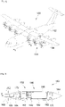
- the Fig. 1 shows an aircraft 100 which has a fuselage 102 on either side of which is fixed a wing 104. Under each wing 104 is fixed at least one propeller propulsion system 150. In the embodiment of the invention presented in Fig. 1 , there are three 150 propulsion systems per 104 wing.
- the Fig. 2 shows the propulsion system 150 which comprises a frame 152 around which are fixed cowls 154 constituting the aerodynamic fairing of the propulsion system 150.
- Frame 152 is attached to fender 104 by any suitable securing means which are not shown in Figs. but which consist for example of fittings, connecting rods, nuts, etc.
- the propulsion system 150 comprises, fixed to the frame 152, a tank 160, a fuel cell 162, an air supply system 164, an electric motor 166, a propeller 168, a cooling system 170 and a system electrical management 172.
- X is called the longitudinal axis of the tank 160 oriented positively in the direction of advance of the aircraft 100
- Y is called the transverse axis of the tank 160 which is horizontal when the aircraft is on the ground
- Z the vertical axis or vertical height when the aircraft is on the ground, these three axes X, Y and Z being mutually orthogonal.
- the axis of rotation of the propeller is here parallel to the longitudinal axis X.
- the air supply system 164 takes ambient air, for example via a scoop in a cowl 154 and filters it, to send it to the fuel cell 162 through an air supply pipe.
- Reservoir 160 contains dihydrogen which is sent to fuel cell 162 through a dihydrogen supply line.
- the fuel cell 162 is a cell in which the generation of an electric voltage is done thanks to the oxidation on one electrode of a reducing fuel, here dihydrogen, coupled with the reduction on the other electrode of an oxidant , here the oxygen of the air.
- a reducing fuel here dihydrogen
- the electrical current generated by the fuel cell 162 is brought to the electrical management system 172 through electrical cables.
- the electric management system 172 comprises for example a controller with an electric converter which converts a direct electric current delivered by the fuel cell 162 to a direct or alternating electric current delivered to the electric motor 166.
- the conversion to the direct or alternating electric current depends on the type of electric motor used.
- the electric current is brought through electric cables to the electric motor 166 and the propeller 168 is fixed on the output shaft of the electric motor 166 possibly through a gearbox.
- the cooling system 170 provides thermal management of the elements in the propulsion system 150.
- the present invention is more particularly focused on the fixing of the tank 160 on the frame 152.
- the chassis 152 comprises a plurality of frames distributed along the longitudinal axis X and beams connecting the frames together in order to form a skeleton on which the covers 154 and the various elements of the propulsion system 150 are fixed.
- the frame 152 includes, among other things, a front frame 180 and a rear frame 182, where the front frame 180 is at the level of the front end of the tank 160 and where the rear frame 182 is at the level of the rear end of the tank 160.
- the front frame 180 and the rear frame 182 here each take the form of a crown arranged around the corresponding end of the tank 160. Even if each crown is circular here, it can take a different shape.
- FIGs. 3 to 7 show the front frame 180 and the tank 160 with fixing means 300 which fix the tank 160 to the front frame 180, but an identical installation can be carried out between the tank 160 and the rear frame 182, and in general, a such an installation can take place between the reservoir 160 and one and/or the other of the frames 180, 182.
- the tank 160 comprises an inner enclosure 184 which consists of a closed inner skin and in which the dihydrogen is stored, and an outer enclosure 186 which consists of an outer skin which surrounds the inner enclosure 184.
- the inner enclosure 184 takes the form of a cylinder of revolution closed at its ends and whose axis is the longitudinal axis X.
- the outer enclosure 186 takes the form of a cylinder of revolution whose axis is the longitudinal axis X and which is also closed at its ends to ensure better rigidity.
- the inner enclosure 184 is held inside the outer enclosure 186 by any appropriate means such as for example spacers fixed between the inner skin and the outer skin.
- the outer enclosure 186 is a structural element, that is to say it is sized to transmit relatively large forces without deforming, while the inner enclosure 184 only has the role of container for the dihydrogen.
- the outer skin comprises stiffeners 310 and 312, and in particular first stiffeners 310 which extend parallel to the longitudinal axis X and second stiffeners 312 which take the form of crowns around the outer skin.
- the fixing means 300 are fixed between the front frame 180 and the outer skin of the outer enclosure 186 and as specified above, the fixing means 300 can be fixed between the rear frame 182 and the outer skin of the enclosure exterior 186, and in general, the fixing means 300 fix the outer skin of the outer enclosure 186 to one and/or the other of the frames 180, 182.
- the external forces which apply to the propulsion system 150 are transmitted to the chassis 152, and in particular to one of the front 180 or rear 182 frames, then, through the fixing means 300 and the outer enclosure 186, to the other among the rear 182 or front 180 frame, and finally to the wing 104 through the securing means.
- a tank system according to the invention thus comprises the tank 160, the frame 152 with a frame 180, 182 and the fixing means 300 which fix the outer skin of the outer enclosure 186 to the frame 180, 182.
- Such an installation therefore does not require beams along the outer skin, that is to say here between the front frame 180 and the rear frame 182, hence saving space and weight.
- fastening means 300 is made in relation to the front frame 180 but it can apply in the same way to the rear frame 182.
- the fixing means 300 comprise a set of fixing means of a first type 304 and a set of fixing means of a second type 302.
- each attachment means of the first type 304 comprises a connecting rod 308 with three points of articulation where two of the points of articulation provide attachment to the front frame 180 and where a third point of articulation provides attachment to the outer skin of the outer enclosure 186.
- each point of articulation of the connecting rod 308 to the front frame 180 takes the form of a male clevis 404a-b of the connecting rod 308, of a female clevis 402a-b secured to the front frame 180 into which the clevis fits male 404a-b and a shaft passing through the female yoke 402a-b and the male yoke 404a-b.
- the axis of the shaft follows a generally radial direction relative to the longitudinal axis X.
- the connection between the female yoke 402a-b and the associated male yoke 404a-b takes the form of a ball joint.
- each female yoke 402a-b secured to the front frame 180 takes the form of a fitting fixed to the front frame 180 for example by welding.
- the third point of articulation of the connecting rod 308 to the outer skin of the outer enclosure 186 takes the form of a ball joint made here by a pin 406 (also called "Spigot") of the connecting rod 308 whose axis is parallel to the longitudinal axis X and which fits into a ball joint integral with the outer skin, here the ball joint is inserted into a membrane 408 of the outer skin, and which extends radially with respect to the longitudinal axis X .
- a pin 406 also called "Spigot”
- the two means of attachment of the first type 304 at 3 and 9 o'clock allow the forces to be taken up along the vertical axis Z, and the means of attachment of the first type 304 at 12 o'clock allows the forces to be taken up along the transverse axis Y.
- the attachment means of the first type 304 at 3 o'clock and at 9 o'clock are identical to the attachment means of the first type 304 at 12 o'clock.
- the fixing means 502 of the Fig. 5 is a variant for a means of attachment of the first type for the recovery of forces along the vertical axis Z, that is to say for the means of attachment of the first type arranged at 3 and 9 o'clock.
- the attachment means of the first type 502 comprises two pairs of links 506, where each link 506 is a link with two points of articulation where one of the points of articulation provides attachment to the front frame 180 and the other point hinge provides attachment to the outer skin of the outer enclosure 186.
- the two pairs of connecting rods 506 of the same fixing means of the first type 502 are arranged on either side of a median plane passing through the longitudinal axis X where the two pairs approach each other at their points of articulation with the outer skin and where the two pairs move away at their points of articulation with the front frame 180.
- the angle of inclination of each connecting rod 506 with respect to the median plane is for example of the order of 45°.
- the two connecting rods 506 of the same first type fastening means 502 form, at their two ends, a female yoke into which a male yoke 504a-b is fitted respectively secured to the front frame 180 and to the outer skin and whose the axis is perpendicular to the direction of the connecting rods 506.
- each male yoke 504a secured to the front frame 180 takes the form of a fitting fixed to the front frame 180 for example by welding.
- each male yoke 504b secured to the outer skin takes the form of an extension of the second stiffeners 312.
- Each attachment means of the second type 302 comprises a connecting rod 306 with two points of articulation where one of the points of articulation provides the attachment to the front frame 180 and where the other point of articulation provides the attachment to the outer skin of the outer enclosure 186.
- the two attachment points of the same connecting rod 306 are aligned parallel to the longitudinal axis X, which allows the forces to be taken up along said longitudinal axis X.
- each point of articulation of the connecting rod 306 here takes the form of a female yoke 602a-b of the connecting rod 306, of a male yoke 604a-b secured respectively to the front frame 180 and to the outer skin of the enclosure outer 186 on which the female yoke 602a-b is fitted and a shaft passing through the female yoke 602a-b and the male yoke 604a-b.
- the axis of the shaft follows a generally tangential direction relative to the longitudinal axis X.
- the connection between the female yoke 602a-b and the associated male yoke 604a-b takes the form of a ball joint.
- each link 306 is a link adjustable in length.
- each male yoke 604a integral with the front frame 180 takes the form of a fitting fixed to the front frame 180 for example by welding.
- each male clevis 604b secured to the outer skin of the outer enclosure 186 on which a female clevis 602a-b of the connecting rod 306 is fitted is one of the first stiffeners 310.
- the second type fixing means 302 there are twelve fixing means of the second type 302, that is to say twelve connecting rods 306, which are distributed around the longitudinal axis X, but of course a A different number is possible depending on the dimensions of the tank 160.
- the second type fixing means 302 are arranged between the first type fixing means 304, 502.
- the propulsion system 150 forms an assembly which attaches under a wing 104 and the frame 152 is the frame of the propulsion system 150, but other arrangements are possible. For example, it is possible to integrate the propulsion system 150 directly into the wing 104 and the frame 152 becomes part of the frame of the wing 104.
Abstract
L'invention concerne un système de réservoir pour un aéronef qui comporte un réservoir (160) comportant une enceinte intérieure constituée d'une peau intérieure fermée destinée à stocker du dihydrogène et une enceinte extérieure (186) constituée d'une peau extérieure qui entoure l'enceinte intérieure, un châssis comportant un cadre avant (180) au niveau d'une extrémité avant du réservoir (160) et des moyens de fixation (300) qui fixent la peau extérieure de l'enceinte extérieure (186) au cadre avant (180).Un tel système permet la reprise d'effort à travers la peau extérieure, limitant ainsi la complexité du châssis.The invention relates to a tank system for an aircraft comprising a tank (160) comprising an inner enclosure made up of a closed inner skin intended to store dihydrogen and an outer enclosure (186) made up of an outer skin which surrounds the inner enclosure, a frame having a front frame (180) at a front end of the tank (160) and attachment means (300) which attaches the outer skin of the outer enclosure (186) to the front frame ( 180). Such a system allows the load to be taken up through the outer skin, thus limiting the complexity of the frame.
Description
La présente invention concerne un système de réservoir pour un aéronef où le système de réservoir comporte un châssis, un réservoir de dihydrogène et des moyens de fixation assurant la fixation du réservoir au châssis. L'invention concerne également un aéronef comportant au moins un tel système de réservoir.The present invention relates to a tank system for an aircraft where the tank system comprises a frame, a dihydrogen tank and fastening means ensuring the fastening of the tank to the frame. The invention also relates to an aircraft comprising at least one such tank system.
Afin de se déplacer, un aéronef comporte un système de propulsion comportant un moteur et une hélice. Le moteur génère un mouvement rotatif qui est transmis à l'hélice.In order to move, an aircraft comprises a propulsion system comprising an engine and a propeller. The motor generates a rotary motion which is transmitted to the propeller.
Il est connu d'utiliser un moteur électrique afin de mettre en mouvement l'hélice, et il est également connu d'utiliser une pile à combustion afin d'alimenter le moteur électrique.It is known to use an electric motor to set the propeller in motion, and it is also known to use a fuel cell to power the electric motor.
Afin d'alimenter la pile à combustible, l'aéronef embarque un réservoir de dihydrogène qui est fixé à la structure de l'aéronef. La structure est un ensemble de poutres fixées entre elles et autour desquelles sont fixés des capots constituant un carénage aérodynamique. Le réservoir est fixé à la structure, mais il est nécessaire de trouver un mode de fixation alternatif qui permet entre autres de diminuer le nombre de poutres pour un gain de poids.In order to supply the fuel cell, the aircraft carries a hydrogen tank which is fixed to the structure of the aircraft. The structure is a set of beams fixed to one another and around which are fixed cowls constituting an aerodynamic fairing. The tank is fixed to the structure, but it is necessary to find an alternative method of fixing which makes it possible, among other things, to reduce the number of beams to save weight.
Un objet de la présente invention est de proposer un système de réservoir qui comporte un châssis, un réservoir de dihydrogène et des moyens de fixation, et qui présente un arrangement optimisé.An object of the present invention is to provide a tank system which comprises a frame, a dihydrogen tank and fastening means, and which has an optimized arrangement.
À cet effet, est proposé un système de réservoir pour un aéronef, ledit système de réservoir comportant :
- un réservoir comportant une enceinte intérieure constituée d'une peau intérieure fermée destinée à stocker du dihydrogène et une enceinte extérieure constituée d'une peau extérieure qui entoure l'enceinte intérieure et prenant la forme d'un cylindre de révolution autour d'un axe longitudinal X,
- un châssis comportant un cadre au niveau d'une extrémité du réservoir, et
- des moyens de fixation qui fixent la peau extérieure de l'enceinte extérieure au cadre et qui comportent trois moyens de fixation d'un premier type répartis autour de l'enceinte extérieure à 3 heures, 12 heures et 9 heures vu selon l'axe longitudinal X et une pluralité de moyens de fixation du deuxième type arrangés entre les moyens de fixation du premier type, où chaque moyen de fixation du deuxième type comporte une bielle à deux points d'articulation où l'un des points d'articulation assure la fixation au cadre et où l'autre point d'articulation assure la fixation à la peau extérieure de l'enceinte extérieure, et où les deux points de fixation d'une même bielle sont alignés parallèlement à l'axe longitudinal X.
- a tank comprising an inner enclosure consisting of a closed inner skin intended to store dihydrogen and an outer enclosure consisting of an outer skin which surrounds the inner enclosure and takes the form of a cylinder of revolution around a longitudinal axis x,
- a frame having a frame at one end of the tank, and
- fixing means which fix the outer skin of the outer enclosure to the frame and which comprise three fixing means of a first type distributed around the outer enclosure at 3 o'clock, 12 o'clock and 9 o'clock seen along the longitudinal axis X and a plurality of second type attachment means arranged between the first type attachment means, wherein each second type attachment means comprises a connecting rod with two pivot points where one of the pivot points provides the attachment to the frame and where the other point of articulation provides attachment to the outer skin of the outer enclosure, and where the two attachment points of the same connecting rod are aligned parallel to the longitudinal axis X.
Un tel système permet la reprise d'effort à travers la peau extérieure, limitant ainsi la complexité du châssis.Such a system allows the recovery of force through the outer skin, thus limiting the complexity of the frame.
Avantageusement, le moyen de fixation du premier type à 12 heures comporte une bielle à trois points d'articulation où deux des points d'articulation assurent la fixation au cadre et où un troisième point d'articulation assure la fixation à la peau extérieure de l'enceinte extérieure.Advantageously, the attachment means of the first type at 12 o'clock comprises a connecting rod with three articulation points where two of the articulation points provide attachment to the frame and where a third articulation point provides attachment to the outer skin of the outer enclosure.
Avantageusement, chaque point d'articulation de la bielle au cadre prend la forme d'une chape mâle de la bielle, d'une chape femelle solidaire du cadre dans laquelle s'emmanche la chape mâle et d'un arbre traversant la chape femelle et la chape mâle et l'axe de l'arbre suit une direction globalement radiale par rapport à l'axe longitudinal X.Advantageously, each point of articulation of the connecting rod to the frame takes the form of a male clevis of the connecting rod, of a female clevis integral with the frame into which the male clevis fits and of a shaft passing through the female clevis and the male yoke and the axis of the shaft follow a generally radial direction with respect to the longitudinal axis X.
Avantageusement, le troisième point d'articulation de la bielle à la peau extérieure de l'enceinte extérieure prend la forme d'une liaison rotule réalisée par un pion de la bielle dont l'axe est parallèle à l'axe longitudinal X et qui s'emmanche dans une rotule solidaire de la peau extérieure.Advantageously, the third point of articulation of the connecting rod to the outer skin of the outer enclosure takes the form of a ball joint made by a pin of the connecting rod whose axis is parallel to the longitudinal axis X and which is sleeve in a ball joint attached to the outer skin.
Selon un mode de réalisation particulier, les moyens de fixation du premier type à 3 heures et à 9 heures sont identiques au moyen de fixation du premier type à 12 heures.According to a particular embodiment, the fixing means of the first type at 3 o'clock and at 9 o'clock are identical to the fixing means of the first type at 12 o'clock.
Selon un mode de réalisation particulier, chaque moyen de fixation du premier type à 3 heures et à 9 heures comporte deux paires de bielles, chaque bielle est une bielle à deux points d'articulation où l'un des points d'articulation assure la fixation au cadre et où l'autre point d'articulation assure la fixation à la peau extérieure de l'enceinte extérieure, les deux paires de bielles d'un même moyen de fixation du premier type sont disposées de part et d'autre d'un plan médian passant par l'axe longitudinal X, les deux paires se rapprochent au niveau de leurs points d'articulation avec la peau extérieure et les deux paires s'éloignent au niveau de leurs points d'articulation avec le cadre.According to a particular embodiment, each fixing means of the first type at 3 o'clock and at 9 o'clock comprises two pairs of connecting rods, each connecting rod is a connecting rod with two articulation points where one of the articulation points ensures the fixing to the frame and where the other point of articulation provides attachment to the outer skin of the outer enclosure, the two pairs of connecting rods of the same first type attachment means are arranged on either side of a median plane passing through the longitudinal axis X, the two pairs approach at their points of articulation with the outer skin and the two pairs move away at their points of articulation with the frame.
Avantageusement, chaque point d'articulation de la bielle prend la forme d'une chape femelle de la bielle, d'une chape mâle solidaire respectivement du cadre et de la peau extérieure de l'enceinte extérieure sur laquelle s'emmanche la chape femelle et d'un arbre traversant la chape femelle et la chape mâle, et l'axe de l'arbre suit une direction globalement tangentielle par rapport à l'axe longitudinal X.Advantageously, each point of articulation of the connecting rod takes the form of a female clevis of the connecting rod, of a male clevis secured respectively to the frame and to the outer skin of the outer enclosure on which the female clevis fits and of a tree crossing the female yoke and the male yoke, and the axis of the shaft follows a generally tangential direction with respect to the longitudinal axis X.
Avantageusement, la peau extérieure comporte des raidisseurs qui s'étendent parallèlement à l'axe longitudinal X, et chaque chape mâle solidaire de la peau extérieure de l'enceinte extérieure sur laquelle s'emmanche une chape femelle de la bielle est un des raidisseurs.Advantageously, the outer skin comprises stiffeners which extend parallel to the longitudinal axis X, and each male yoke secured to the outer skin of the outer enclosure onto which a female yoke of the connecting rod is fitted is one of the stiffeners.
L'invention propose également un aéronef comportant au moins un système de réservoir selon l'une des variantes précédentes.The invention also proposes an aircraft comprising at least one tank system according to one of the preceding variants.
Les caractéristiques de l'invention mentionnées ci-dessus, ainsi que d'autres, apparaîtront plus clairement à la lecture de la description suivante d'un exemple de réalisation, ladite description étant faite en relation avec les dessins joints, parmi lesquels :
-
Fig. 1 est une vue en perspective d'un aéronef comportant une pluralité de systèmes de propulsion à hélice selon l'invention, -
Fig. 2 est une représentation schématique en coupe d'un système de propulsion à hélice embarquant un système de réservoir selon l'invention, -
Fig. 3 est une vue en perspective d'une extrémité avant du système de réservoir selon l'invention, -
Fig. 4 est un agrandissement d'une bielle à trois points selon le détail IV de laFig. 3 et selon un premier mode de réalisation de l'invention, -
Fig. 5 est une vue similaire à celle de laFig. 4 pour un deuxième mode de réalisation de l'invention, -
Fig. 6 est un agrandissement d'un tirant selon le détail VI de laFig. 3 , et -
Fig. 7 est une représentation schématique d'une vue de derrière du système de réservoir selon l'invention sans le cadre arrière.
-
Fig. 1 is a perspective view of an aircraft comprising a plurality of propeller propulsion systems according to the invention, -
Fig. 2 is a schematic sectional representation of a propeller propulsion system carrying a tank system according to the invention, -
Fig. 3 is a perspective view of a front end of the tank system according to the invention, -
Fig. 4 is an enlargement of a three-point connecting rod according to detail IV of theFig. 3 and according to a first embodiment of the invention, -
Fig. 5 is a view similar to that of theFig. 4 for a second embodiment of the invention, -
Fig. 6 is an enlargement of a tie according to detail VI of theFig. 3 , and -
Fig. 7 is a schematic representation of a rear view of the tank system according to the invention without the rear frame.
Dans la description qui suit, les termes relatifs à une position sont pris en référence à un aéronef en position d'avancement, c'est-à-dire comme il est représenté sur la
La
La
Le châssis 152 est fixé à l'aile 104 par tous moyens d'arrimage appropriés qui ne sont pas représentés sur les Figs. mais qui sont constitués par exemple de ferrures, de bielles, d'écrous, etc.
Dans le mode de réalisation de l'invention présenté à la
Dans la description qui suit, et par convention, on appelle X l'axe longitudinal du réservoir 160 orienté positivement dans le sens d'avancement de l'aéronef 100, on appelle Y l'axe transversal du réservoir 160 qui est horizontal lorsque l'aéronef est au sol, et Z l'axe vertical ou hauteur verticale lorsque l'aéronef est au sol, ces trois axes X, Y et Z étant orthogonaux entre eux. L'axe de rotation de l'hélice est ici parallèle à l'axe longitudinal X.In the following description, and by convention, X is called the longitudinal axis of the
Le système d'apport d'air 164 prélève de l'air ambiant par exemple par une écope dans un capot 154 et le filtre, pour l'envoyer vers la pile à combustible 162 à travers une canalisation d'apport d'air.The
Le réservoir 160 contient du dihydrogène qui est envoyé vers la pile à combustible 162 à travers une canalisation d'apport de dihydrogène.
La pile à combustible 162 est une pile dans laquelle la génération d'une tension électrique se fait grâce à l'oxydation sur une électrode d'un combustible réducteur, ici le dihydrogène, couplée à la réduction sur l'autre électrode d'un oxydant, ici l'oxygène de l'air.The
Le courant électrique généré par la pile à combustible 162 est amené jusqu'au système de gestion électrique 172 à travers des câbles électriques. Le système de gestion électrique 172 comporte par exemple un contrôleur avec un convertisseur électrique qui convertit un courant électrique continu délivré par la pile à combustible 162 vers un courant électrique continu ou alternatif délivré au moteur électrique 166. La conversion vers le courant électrique continu ou alternatif dépend du type de moteur électrique utilisé.The electrical current generated by the
En sortie du système de gestion électrique 172, le courant électrique est amené à travers des câbles électriques jusqu'au moteur électrique 166 et l'hélice 168 est fixée sur l'arbre de sortie du moteur électrique 166 éventuellement à travers une boîte de vitesse.At the output of the
Le système de refroidissement 170 assure la gestion thermique des éléments dans le système de propulsion 150.The
La présente invention est plus particulièrement focalisée sur la fixation du réservoir 160 sur le châssis 152.The present invention is more particularly focused on the fixing of the
Le châssis 152 comporte une pluralité de cadres répartis le long de l'axe longitudinal X et de poutrelles reliant entre eux les cadres afin de former un squelette sur lequel se fixent les capots 154 et les différents éléments du système de propulsion 150.The
Le châssis 152 comporte entre autres un cadre avant 180 et un cadre arrière 182, où le cadre avant 180 est au niveau de l'extrémité avant du réservoir 160 et où le cadre arrière 182 est au niveau de l'extrémité arrière du réservoir 160. Le cadre avant 180 et le cadre arrière 182 prennent ici chacun la forme d'une couronne disposée autour de l'extrémité correspondante du réservoir 160. Même si chaque couronne est ici circulaire, elle peut prendre une forme différente.The
Les
Le réservoir 160 comporte une enceinte intérieure 184 qui est constituée d'une peau intérieure fermée et dans laquelle est stocké le dihydrogène, et une enceinte extérieure 186 qui est constituée d'une peau extérieure qui entoure l'enceinte intérieure 184.The
Dans le mode de réalisation présenté ici, l'enceinte intérieure 184 prend la forme d'un cylindre de révolution fermé à ses extrémités et dont l'axe est l'axe longitudinal X.In the embodiment presented here, the
De la même manière, l'enceinte extérieure 186 prend la forme d'un cylindre de révolution dont l'axe est l'axe longitudinal X et qui est également fermé à ses extrémités pour assurer une meilleure rigidité.In the same way, the
L'enceinte intérieure 184 est maintenue à l'intérieur de l'enceinte extérieure 186 par tous moyens appropriés comme par exemple des entretoises fixées entre la peau intérieure et la peau extérieure.The
L'enceinte extérieure 186 est un élément structurel, c'est-à-dire qu'il est dimensionné pour transmettre des efforts relativement importants sans se déformer, tandis que l'enceinte intérieure 184 a uniquement un rôle de contenant pour le dihydrogène.The
Pour renforcer la structure de l'enceinte extérieure 186, la peau extérieure comporte des raidisseurs 310 et 312, et en particulier des premiers raidisseurs 310 qui s'étendent parallèlement à l'axe longitudinal X et des deuxièmes raidisseurs 312 qui prennent la forme de couronnes autour de la peau extérieure.To reinforce the structure of the
Les moyens de fixation 300 sont fixés entre le cadre avant 180 et la peau extérieure de l'enceinte extérieure 186 et comme précisé ci-dessus, les moyens de fixation 300 peuvent être fixés entre le cadre arrière 182 et la peau extérieure de l'enceinte extérieure 186, et d'une manière générale, les moyens de fixation 300 fixent la peau extérieure de l'enceinte extérieure 186 à l'un et/ou l'autre des cadres 180, 182.The fixing means 300 are fixed between the
Ainsi, les efforts extérieurs qui s'appliquent sur le système de propulsion 150 se transmettent au châssis 152, et en particulier à un des cadres avant 180 ou arrière 182, puis, à travers les moyens de fixation 300 et l'enceinte extérieure 186, à l'autre parmi le cadre arrière 182 ou avant 180, et enfin à l'aile 104 à travers les moyens d'arrimage.Thus, the external forces which apply to the
Un système de réservoir selon l'invention comporte ainsi le réservoir 160, le châssis 152 avec un cadre 180, 182 et les moyens de fixation 300 qui fixent la peau extérieure de l'enceinte extérieure 186 au cadre 180, 182.A tank system according to the invention thus comprises the
Une telle installation ne nécessite donc pas de poutrelles le long de la peau extérieure, c'est-à-dire ici entre le cadre avant 180 et le cadre arrière 182, d'où un gain de place et de poids.Such an installation therefore does not require beams along the outer skin, that is to say here between the
La description des moyens de fixation 300 est faite en rapport avec le cadre avant 180 mais elle peut s'appliquer de la même manière au cadre arrière 182.The description of the fastening means 300 is made in relation to the
Les moyens de fixation 300 comprennent un ensemble de moyens de fixation d'un premier type 304 et un ensemble de moyens de fixation d'un deuxième type 302.The fixing means 300 comprise a set of fixing means of a
Dans le mode de réalisation de la
Comme le montre la
Dans le mode de réalisation de l'invention présenté ici, chaque chape femelle 402a-b solidaire du cadre avant 180 prend la forme d'une ferrure fixée au cadre avant 180 par exemple par soudure.In the embodiment of the invention presented here, each
Comme le montre la
Il y a trois moyens de fixation du premier type 304 qui sont répartis autour de l'enceinte extérieure 186 à 3 heures, 12 heures et 9 heures vu selon l'axe longitudinal X.There are three means of attachment of the
Les deux moyens de fixation du premier type 304 à 3 et 9 heures permettent une reprise des efforts selon l'axe vertical Z, et le moyen de fixation du premier type 304 à 12 heures permet une reprise des efforts selon l'axe transversal Y.The two means of attachment of the
Dans le mode de réalisation de l'invention de la
Le moyen de fixation 502 de la
Le moyen de fixation du premier type 502 comporte deux paires de bielles 506, où chaque bielle 506 est une bielle à deux points d'articulation où l'un des points d'articulation assure la fixation au cadre avant 180 et où l'autre point d'articulation assure la fixation à la peau extérieure de l'enceinte extérieure 186.The attachment means of the
Les deux paires de bielles 506 d'un même moyen de fixation du premier type 502 sont disposées de part et d'autre d'un plan médian passant par l'axe longitudinal X où les deux paires se rapprochent au niveau de leurs points d'articulation avec la peau extérieure et où les deux paires s'éloignent au niveau de leurs points d'articulation avec le cadre avant 180. L'angle d'inclinaison de chaque bielle 506 par rapport au plan médian est par exemple de l'ordre de 45°.The two pairs of connecting
Comme le montre la
Dans le mode de réalisation de l'invention présenté ici, chaque chape mâle 504a solidaire du cadre avant 180 prend la forme d'une ferrure fixée au cadre avant 180 par exemple par soudure.In the embodiment of the invention presented here, each
Dans le mode de réalisation de l'invention présenté ici, chaque chape mâle 504b solidaire de la peau extérieure prend la forme d'une extension des deuxièmes raidisseurs 312.In the embodiment of the invention presented here, each
Chaque moyen de fixation du deuxième type 302 comporte une bielle 306 à deux points d'articulation où l'un des points d'articulation assure la fixation au cadre avant 180 et où l'autre point d'articulation assure la fixation à la peau extérieure de l'enceinte extérieure 186. Les deux points de fixation d'une même bielle 306 sont alignés parallèlement à l'axe longitudinal X ce qui permet une reprise des efforts selon ledit axe longitudinal X.Each attachment means of the
Comme le montre la
Pour permettre une adaptation de la longueur de chaque bielle 306 en fonction de la position du cadre avant 180 et de l'enceinte extérieure 186, chaque bielle 306 est une bielle réglable en longueur.To allow adaptation of the length of each link 306 according to the position of the
Dans le mode de réalisation de l'invention présenté ici, chaque chape mâle 604a solidaire du cadre avant 180 prend la forme d'une ferrure fixée au cadre avant 180 par exemple par soudure.In the embodiment of the invention presented here, each
Dans le mode de réalisation de l'invention présenté ici, chaque chape mâle 604b solidaire de la peau extérieure de l'enceinte extérieure 186 sur laquelle s'emmanche une chape femelle 602a-b de la bielle 306 est un des premiers raidisseurs 310.In the embodiment of the invention presented here, each
Dans le mode de réalisation de l'invention présenté ici, il y a douze moyens de fixation du deuxième type 302, c'est-à-dire douze bielles 306, qui sont répartis autour de l'axe longitudinal X, mais bien sûr un nombre différent est envisageable selon les dimensions du réservoir 160. Les moyens de fixation du deuxième type 302 sont arrangés entre les moyens de fixation du premier type 304, 502.In the embodiment of the invention presented here, there are twelve fixing means of the
Dans la description ci-dessus, le système de propulsion 150 forme un ensemble qui se fixe sous une aile 104 et le châssis 152 est le châssis du système de propulsion 150, mais d'autres arrangements sont possibles. Par exemple, il est possible d'intégrer directement le système de propulsion 150 dans l'aile 104 et le châssis 152 devient une partie du châssis de l'aile 104.In the above description, the
Claims (9)
Applications Claiming Priority (1)
| Application Number | Priority Date | Filing Date | Title |
|---|---|---|---|
| FR2105251A FR3123050A1 (en) | 2021-05-20 | 2021-05-20 | TANK SYSTEM COMPRISING A FRAME, A DIHYDROGEN TANK AND MEANS FOR ATTACHING THE TANK TO THE FRAME |
Publications (2)
| Publication Number | Publication Date |
|---|---|
| EP4091944A1 true EP4091944A1 (en) | 2022-11-23 |
| EP4091944B1 EP4091944B1 (en) | 2024-03-20 |
Family
ID=76601421
Family Applications (1)
| Application Number | Title | Priority Date | Filing Date |
|---|---|---|---|
| EP22174215.8A Active EP4091944B1 (en) | 2021-05-20 | 2022-05-19 | Tank system comprising a frame, a dihydrogen tank and means for attaching the tank to the frame |
Country Status (4)
| Country | Link |
|---|---|
| US (1) | US20220371743A1 (en) |
| EP (1) | EP4091944B1 (en) |
| CN (1) | CN115367126A (en) |
| FR (1) | FR3123050A1 (en) |
Families Citing this family (1)
| Publication number | Priority date | Publication date | Assignee | Title |
|---|---|---|---|---|
| US11958625B1 (en) * | 2023-06-22 | 2024-04-16 | ZeroAvia, Inc. | Aerodynamic hydrogen tanks |
Citations (3)
| Publication number | Priority date | Publication date | Assignee | Title |
|---|---|---|---|---|
| US3951362A (en) * | 1974-05-13 | 1976-04-20 | The Boeing Company | Cryogenic tank and aircraft structural interface |
| FR3001713A1 (en) * | 2013-02-05 | 2014-08-08 | Astrium Sas | DEVICE FOR RETAINING A TANK IN AN AIRCRAFT |
| FR3097202A1 (en) * | 2019-06-14 | 2020-12-18 | Airbus | AUTONOMOUS PROPULSION SYSTEM WITH PROPELLER FOR AN AIRCRAFT, LEDIT AUTONOMOUS PROPULSION SYSTEM WITH PROPELLER CONTAINING A FUEL CELL |
Family Cites Families (12)
| Publication number | Priority date | Publication date | Assignee | Title |
|---|---|---|---|---|
| US3243150A (en) * | 1964-04-09 | 1966-03-29 | Boeing Co | Aerospace vehicle and tank structure |
| FR2793767B1 (en) * | 1999-05-17 | 2001-09-21 | Aerospatiale Airbus | HANGING DEVICE OF AN AIRCRAFT ENGINE |
| US6347719B1 (en) * | 2000-07-14 | 2002-02-19 | Hughes Electronics Corporation | Light weight hydrogen tank |
| FR2828167B1 (en) * | 2001-07-31 | 2003-11-21 | Airbus France | DEVICE FOR HANGING AN ENGINE ON AN AIRCRAFT |
| US6843449B1 (en) * | 2004-02-09 | 2005-01-18 | General Electric Company | Fail-safe aircraft engine mounting system |
| US8348191B2 (en) * | 2010-07-14 | 2013-01-08 | Spirit Aerosystems, Inc. | Fail-safe aircraft engine mounting apparatus |
| US10279921B2 (en) * | 2012-10-31 | 2019-05-07 | General Electric Company | Cryogenic tank |
| FR3001714B1 (en) * | 2013-02-05 | 2016-08-26 | Astrium Sas | DEVICE FOR SUPPORTING AND MAINTAINING CRYOGENIC RESERVOIRS |
| WO2016025885A1 (en) * | 2014-08-14 | 2016-02-18 | Mcgee Craig S | Exhaust arrangement for aircraft having sensor |
| US10306984B2 (en) * | 2016-08-30 | 2019-06-04 | The Boeing Company | Toroidal support structures |
| WO2020003181A1 (en) * | 2018-06-27 | 2020-01-02 | H3 Dynamics Holdings Pte. Ltd. | Distributed electric energy pods network and associated electrically powered vehicle |
| FR3096028B1 (en) * | 2019-05-14 | 2021-05-21 | Airbus Operations Sas | REAR ENGINE ATTACHMENT FOR AN AIRCRAFT ENGINE |
-
2021
- 2021-05-20 FR FR2105251A patent/FR3123050A1/en active Pending
-
2022
- 2022-05-18 US US17/747,200 patent/US20220371743A1/en active Pending
- 2022-05-19 EP EP22174215.8A patent/EP4091944B1/en active Active
- 2022-05-19 CN CN202210557600.2A patent/CN115367126A/en active Pending
Patent Citations (3)
| Publication number | Priority date | Publication date | Assignee | Title |
|---|---|---|---|---|
| US3951362A (en) * | 1974-05-13 | 1976-04-20 | The Boeing Company | Cryogenic tank and aircraft structural interface |
| FR3001713A1 (en) * | 2013-02-05 | 2014-08-08 | Astrium Sas | DEVICE FOR RETAINING A TANK IN AN AIRCRAFT |
| FR3097202A1 (en) * | 2019-06-14 | 2020-12-18 | Airbus | AUTONOMOUS PROPULSION SYSTEM WITH PROPELLER FOR AN AIRCRAFT, LEDIT AUTONOMOUS PROPULSION SYSTEM WITH PROPELLER CONTAINING A FUEL CELL |
Also Published As
| Publication number | Publication date |
|---|---|
| EP4091944B1 (en) | 2024-03-20 |
| CN115367126A (en) | 2022-11-22 |
| FR3123050A1 (en) | 2022-11-25 |
| US20220371743A1 (en) | 2022-11-24 |
Similar Documents
| Publication | Publication Date | Title |
|---|---|---|
| EP1773660B1 (en) | Aircraft engine unit | |
| CA2697380C (en) | Cradle for holding a fan coil mounted on the attachment pylon and on the nacelle air intake | |
| EP2554478B1 (en) | Articulated fairing for nacelle members supported by these nacelle members in a closed position | |
| FR3097202A1 (en) | AUTONOMOUS PROPULSION SYSTEM WITH PROPELLER FOR AN AIRCRAFT, LEDIT AUTONOMOUS PROPULSION SYSTEM WITH PROPELLER CONTAINING A FUEL CELL | |
| EP2137072B1 (en) | Device for attaching an aircraft engine and aircraft comprising at least one such device | |
| EP1773659B9 (en) | Engine assembly for aircraft | |
| FR2903666A1 (en) | AIRCRAFT ENGINE ASSEMBLY COMPRISING AERODYNAMIC JOINT COVERAGE MOUNTED ON TWO SEPARATE ELEMENTS | |
| FR2903383A1 (en) | Aircraft`s jet engine locking device, has mechanical connection with clearance between rear end of rods and support fitting integrated to box, where connection is placed in rear end mounted on rudder bar of thrust reacting device | |
| EP1480876B1 (en) | Engine pylon suspension attachment of an engine under an aircraft wing section | |
| FR2806699A1 (en) | PUSH RETURN DEVICE CAPABLE OF CONNECTING A TURBOMOTOR AND AN AIRCRAFT MAT | |
| FR2891251A1 (en) | ENGINE ATTACHING MAT FOR AN AIRCRAFT | |
| FR2917713A1 (en) | APPARATUS FOR ATTACHING AN AIRCRAFT ENGINE AND AIRCRAFT HAVING AT LEAST ONE SUCH DEVICE. | |
| EP1928738A1 (en) | Engine mounting structure interposed between an aircraft wing system and said engine | |
| EP4091944B1 (en) | Tank system comprising a frame, a dihydrogen tank and means for attaching the tank to the frame | |
| EP3757012B1 (en) | Aircraft propeller assembly comprising improved primary mast structure and front engine mount | |
| FR3097201A1 (en) | AIRCRAFT CONTAINING A PLURALITY OF AUTONOMOUS PROPULSION SYSTEMS WITH A FUEL CELL | |
| EP1535837A1 (en) | Engine suspension attcchment device of an engine to an aircraft wing | |
| FR3059298A1 (en) | AIRCRAFT ASSEMBLY COMPRISING A "OPEN ROTOR PULLER" TYPE ENGINE AND MEANS FOR HINGING IT WITH THE RIGID STRUCTURE OF A COUPLING MAT | |
| EP1571082A1 (en) | Aircraft engine attachment onto a wing pylon | |
| EP2763898A1 (en) | Aircraft propulsion assembly | |
| EP2763897A1 (en) | Aircraft propulsion assembly | |
| FR3049575B1 (en) | PROPULSIVE DEVICE WITH ACTIVE PORTABILITY | |
| FR2887850A1 (en) | Aircraft engine mounting structure has thrust force take-up assembly fixed to point on rigid structure separate from front and rear coupling points | |
| FR2887522A1 (en) | Aircraft shipset, has turboshaft engine fixing mast with units to fix box forming rigid structure under box forming aerofoil unit, where fixing units have fastener with insert fitting placed inside structure and box forming aerofoil unit | |
| FR2993535A1 (en) | Propelling assembly i.e. double flow turbojet assembly, for commercial plane, has force recovery units, where one recovery unit is arranged behind another recovery unit according to longitudinal direction and is integrated into side beams |
Legal Events
| Date | Code | Title | Description |
|---|---|---|---|
| PUAI | Public reference made under article 153(3) epc to a published international application that has entered the european phase |
Free format text: ORIGINAL CODE: 0009012 |
|
| STAA | Information on the status of an ep patent application or granted ep patent |
Free format text: STATUS: THE APPLICATION HAS BEEN PUBLISHED |
|
| AK | Designated contracting states |
Kind code of ref document: A1 Designated state(s): AL AT BE BG CH CY CZ DE DK EE ES FI FR GB GR HR HU IE IS IT LI LT LU LV MC MK MT NL NO PL PT RO RS SE SI SK SM TR |
|
| STAA | Information on the status of an ep patent application or granted ep patent |
Free format text: STATUS: REQUEST FOR EXAMINATION WAS MADE |
|
| 17P | Request for examination filed |
Effective date: 20230504 |
|
| RBV | Designated contracting states (corrected) |
Designated state(s): AL AT BE BG CH CY CZ DE DK EE ES FI FR GB GR HR HU IE IS IT LI LT LU LV MC MK MT NL NO PL PT RO RS SE SI SK SM TR |
|
| GRAP | Despatch of communication of intention to grant a patent |
Free format text: ORIGINAL CODE: EPIDOSNIGR1 |
|
| STAA | Information on the status of an ep patent application or granted ep patent |
Free format text: STATUS: GRANT OF PATENT IS INTENDED |
|
| INTG | Intention to grant announced |
Effective date: 20231018 |
|
| RAP3 | Party data changed (applicant data changed or rights of an application transferred) |
Owner name: AIRBUS OPERATIONS, S.L. Owner name: AIRBUS OPERATIONS (S.A.S.) Owner name: AIRBUS SAS |
|
| GRAS | Grant fee paid |
Free format text: ORIGINAL CODE: EPIDOSNIGR3 |
|
| GRAA | (expected) grant |
Free format text: ORIGINAL CODE: 0009210 |
|
| STAA | Information on the status of an ep patent application or granted ep patent |
Free format text: STATUS: THE PATENT HAS BEEN GRANTED |
|
| AK | Designated contracting states |
Kind code of ref document: B1 Designated state(s): AL AT BE BG CH CY CZ DE DK EE ES FI FR GB GR HR HU IE IS IT LI LT LU LV MC MK MT NL NO PL PT RO RS SE SI SK SM TR |
|
| REG | Reference to a national code |
Ref country code: GB Ref legal event code: FG4D Free format text: NOT ENGLISH |
|
| REG | Reference to a national code |
Ref country code: CH Ref legal event code: EP |
|
| REG | Reference to a national code |
Ref country code: DE Ref legal event code: R096 Ref document number: 602022002407 Country of ref document: DE |