EP4091858A1 - Electric vehicle - Google Patents
Electric vehicle Download PDFInfo
- Publication number
- EP4091858A1 EP4091858A1 EP22173587.1A EP22173587A EP4091858A1 EP 4091858 A1 EP4091858 A1 EP 4091858A1 EP 22173587 A EP22173587 A EP 22173587A EP 4091858 A1 EP4091858 A1 EP 4091858A1
- Authority
- EP
- European Patent Office
- Prior art keywords
- electric motor
- brake
- wheel
- electric
- electromagnetic brake
- Prior art date
- Legal status (The legal status is an assumption and is not a legal conclusion. Google has not performed a legal analysis and makes no representation as to the accuracy of the status listed.)
- Pending
Links
Images



Classifications
-
- B—PERFORMING OPERATIONS; TRANSPORTING
- B60—VEHICLES IN GENERAL
- B60K—ARRANGEMENT OR MOUNTING OF PROPULSION UNITS OR OF TRANSMISSIONS IN VEHICLES; ARRANGEMENT OR MOUNTING OF PLURAL DIVERSE PRIME-MOVERS IN VEHICLES; AUXILIARY DRIVES FOR VEHICLES; INSTRUMENTATION OR DASHBOARDS FOR VEHICLES; ARRANGEMENTS IN CONNECTION WITH COOLING, AIR INTAKE, GAS EXHAUST OR FUEL SUPPLY OF PROPULSION UNITS IN VEHICLES
- B60K20/00—Arrangement or mounting of change-speed gearing control devices in vehicles
-
- B—PERFORMING OPERATIONS; TRANSPORTING
- B60—VEHICLES IN GENERAL
- B60L—PROPULSION OF ELECTRICALLY-PROPELLED VEHICLES; SUPPLYING ELECTRIC POWER FOR AUXILIARY EQUIPMENT OF ELECTRICALLY-PROPELLED VEHICLES; ELECTRODYNAMIC BRAKE SYSTEMS FOR VEHICLES IN GENERAL; MAGNETIC SUSPENSION OR LEVITATION FOR VEHICLES; MONITORING OPERATING VARIABLES OF ELECTRICALLY-PROPELLED VEHICLES; ELECTRIC SAFETY DEVICES FOR ELECTRICALLY-PROPELLED VEHICLES
- B60L15/00—Methods, circuits, or devices for controlling the traction-motor speed of electrically-propelled vehicles
- B60L15/20—Methods, circuits, or devices for controlling the traction-motor speed of electrically-propelled vehicles for control of the vehicle or its driving motor to achieve a desired performance, e.g. speed, torque, programmed variation of speed
- B60L15/2009—Methods, circuits, or devices for controlling the traction-motor speed of electrically-propelled vehicles for control of the vehicle or its driving motor to achieve a desired performance, e.g. speed, torque, programmed variation of speed for braking
-
- B—PERFORMING OPERATIONS; TRANSPORTING
- B60—VEHICLES IN GENERAL
- B60K—ARRANGEMENT OR MOUNTING OF PROPULSION UNITS OR OF TRANSMISSIONS IN VEHICLES; ARRANGEMENT OR MOUNTING OF PLURAL DIVERSE PRIME-MOVERS IN VEHICLES; AUXILIARY DRIVES FOR VEHICLES; INSTRUMENTATION OR DASHBOARDS FOR VEHICLES; ARRANGEMENTS IN CONNECTION WITH COOLING, AIR INTAKE, GAS EXHAUST OR FUEL SUPPLY OF PROPULSION UNITS IN VEHICLES
- B60K1/00—Arrangement or mounting of electrical propulsion units
-
- B—PERFORMING OPERATIONS; TRANSPORTING
- B60—VEHICLES IN GENERAL
- B60K—ARRANGEMENT OR MOUNTING OF PROPULSION UNITS OR OF TRANSMISSIONS IN VEHICLES; ARRANGEMENT OR MOUNTING OF PLURAL DIVERSE PRIME-MOVERS IN VEHICLES; AUXILIARY DRIVES FOR VEHICLES; INSTRUMENTATION OR DASHBOARDS FOR VEHICLES; ARRANGEMENTS IN CONNECTION WITH COOLING, AIR INTAKE, GAS EXHAUST OR FUEL SUPPLY OF PROPULSION UNITS IN VEHICLES
- B60K17/00—Arrangement or mounting of transmissions in vehicles
- B60K17/04—Arrangement or mounting of transmissions in vehicles characterised by arrangement, location or kind of gearing
- B60K17/12—Arrangement or mounting of transmissions in vehicles characterised by arrangement, location or kind of gearing of electric gearing
-
- B—PERFORMING OPERATIONS; TRANSPORTING
- B60—VEHICLES IN GENERAL
- B60K—ARRANGEMENT OR MOUNTING OF PROPULSION UNITS OR OF TRANSMISSIONS IN VEHICLES; ARRANGEMENT OR MOUNTING OF PLURAL DIVERSE PRIME-MOVERS IN VEHICLES; AUXILIARY DRIVES FOR VEHICLES; INSTRUMENTATION OR DASHBOARDS FOR VEHICLES; ARRANGEMENTS IN CONNECTION WITH COOLING, AIR INTAKE, GAS EXHAUST OR FUEL SUPPLY OF PROPULSION UNITS IN VEHICLES
- B60K17/00—Arrangement or mounting of transmissions in vehicles
- B60K17/04—Arrangement or mounting of transmissions in vehicles characterised by arrangement, location or kind of gearing
- B60K17/14—Arrangement or mounting of transmissions in vehicles characterised by arrangement, location or kind of gearing the motor of fluid or electric gearing being disposed in, or adjacent to, traction wheel
-
- B—PERFORMING OPERATIONS; TRANSPORTING
- B60—VEHICLES IN GENERAL
- B60L—PROPULSION OF ELECTRICALLY-PROPELLED VEHICLES; SUPPLYING ELECTRIC POWER FOR AUXILIARY EQUIPMENT OF ELECTRICALLY-PROPELLED VEHICLES; ELECTRODYNAMIC BRAKE SYSTEMS FOR VEHICLES IN GENERAL; MAGNETIC SUSPENSION OR LEVITATION FOR VEHICLES; MONITORING OPERATING VARIABLES OF ELECTRICALLY-PROPELLED VEHICLES; ELECTRIC SAFETY DEVICES FOR ELECTRICALLY-PROPELLED VEHICLES
- B60L7/00—Electrodynamic brake systems for vehicles in general
- B60L7/006—Dynamic electric braking by reversing current, i.e. plugging
-
- B—PERFORMING OPERATIONS; TRANSPORTING
- B60—VEHICLES IN GENERAL
- B60L—PROPULSION OF ELECTRICALLY-PROPELLED VEHICLES; SUPPLYING ELECTRIC POWER FOR AUXILIARY EQUIPMENT OF ELECTRICALLY-PROPELLED VEHICLES; ELECTRODYNAMIC BRAKE SYSTEMS FOR VEHICLES IN GENERAL; MAGNETIC SUSPENSION OR LEVITATION FOR VEHICLES; MONITORING OPERATING VARIABLES OF ELECTRICALLY-PROPELLED VEHICLES; ELECTRIC SAFETY DEVICES FOR ELECTRICALLY-PROPELLED VEHICLES
- B60L7/00—Electrodynamic brake systems for vehicles in general
- B60L7/10—Dynamic electric regenerative braking
- B60L7/18—Controlling the braking effect
-
- B—PERFORMING OPERATIONS; TRANSPORTING
- B60—VEHICLES IN GENERAL
- B60L—PROPULSION OF ELECTRICALLY-PROPELLED VEHICLES; SUPPLYING ELECTRIC POWER FOR AUXILIARY EQUIPMENT OF ELECTRICALLY-PROPELLED VEHICLES; ELECTRODYNAMIC BRAKE SYSTEMS FOR VEHICLES IN GENERAL; MAGNETIC SUSPENSION OR LEVITATION FOR VEHICLES; MONITORING OPERATING VARIABLES OF ELECTRICALLY-PROPELLED VEHICLES; ELECTRIC SAFETY DEVICES FOR ELECTRICALLY-PROPELLED VEHICLES
- B60L7/00—Electrodynamic brake systems for vehicles in general
- B60L7/24—Electrodynamic brake systems for vehicles in general with additional mechanical or electromagnetic braking
-
- B—PERFORMING OPERATIONS; TRANSPORTING
- B60—VEHICLES IN GENERAL
- B60L—PROPULSION OF ELECTRICALLY-PROPELLED VEHICLES; SUPPLYING ELECTRIC POWER FOR AUXILIARY EQUIPMENT OF ELECTRICALLY-PROPELLED VEHICLES; ELECTRODYNAMIC BRAKE SYSTEMS FOR VEHICLES IN GENERAL; MAGNETIC SUSPENSION OR LEVITATION FOR VEHICLES; MONITORING OPERATING VARIABLES OF ELECTRICALLY-PROPELLED VEHICLES; ELECTRIC SAFETY DEVICES FOR ELECTRICALLY-PROPELLED VEHICLES
- B60L7/00—Electrodynamic brake systems for vehicles in general
- B60L7/24—Electrodynamic brake systems for vehicles in general with additional mechanical or electromagnetic braking
- B60L7/26—Controlling the braking effect
-
- B—PERFORMING OPERATIONS; TRANSPORTING
- B60—VEHICLES IN GENERAL
- B60L—PROPULSION OF ELECTRICALLY-PROPELLED VEHICLES; SUPPLYING ELECTRIC POWER FOR AUXILIARY EQUIPMENT OF ELECTRICALLY-PROPELLED VEHICLES; ELECTRODYNAMIC BRAKE SYSTEMS FOR VEHICLES IN GENERAL; MAGNETIC SUSPENSION OR LEVITATION FOR VEHICLES; MONITORING OPERATING VARIABLES OF ELECTRICALLY-PROPELLED VEHICLES; ELECTRIC SAFETY DEVICES FOR ELECTRICALLY-PROPELLED VEHICLES
- B60L2200/00—Type of vehicles
- B60L2200/40—Working vehicles
-
- B—PERFORMING OPERATIONS; TRANSPORTING
- B60—VEHICLES IN GENERAL
- B60L—PROPULSION OF ELECTRICALLY-PROPELLED VEHICLES; SUPPLYING ELECTRIC POWER FOR AUXILIARY EQUIPMENT OF ELECTRICALLY-PROPELLED VEHICLES; ELECTRODYNAMIC BRAKE SYSTEMS FOR VEHICLES IN GENERAL; MAGNETIC SUSPENSION OR LEVITATION FOR VEHICLES; MONITORING OPERATING VARIABLES OF ELECTRICALLY-PROPELLED VEHICLES; ELECTRIC SAFETY DEVICES FOR ELECTRICALLY-PROPELLED VEHICLES
- B60L2240/00—Control parameters of input or output; Target parameters
- B60L2240/10—Vehicle control parameters
- B60L2240/12—Speed
-
- B—PERFORMING OPERATIONS; TRANSPORTING
- B60—VEHICLES IN GENERAL
- B60L—PROPULSION OF ELECTRICALLY-PROPELLED VEHICLES; SUPPLYING ELECTRIC POWER FOR AUXILIARY EQUIPMENT OF ELECTRICALLY-PROPELLED VEHICLES; ELECTRODYNAMIC BRAKE SYSTEMS FOR VEHICLES IN GENERAL; MAGNETIC SUSPENSION OR LEVITATION FOR VEHICLES; MONITORING OPERATING VARIABLES OF ELECTRICALLY-PROPELLED VEHICLES; ELECTRIC SAFETY DEVICES FOR ELECTRICALLY-PROPELLED VEHICLES
- B60L2240/00—Control parameters of input or output; Target parameters
- B60L2240/10—Vehicle control parameters
- B60L2240/36—Temperature of vehicle components or parts
-
- B—PERFORMING OPERATIONS; TRANSPORTING
- B60—VEHICLES IN GENERAL
- B60L—PROPULSION OF ELECTRICALLY-PROPELLED VEHICLES; SUPPLYING ELECTRIC POWER FOR AUXILIARY EQUIPMENT OF ELECTRICALLY-PROPELLED VEHICLES; ELECTRODYNAMIC BRAKE SYSTEMS FOR VEHICLES IN GENERAL; MAGNETIC SUSPENSION OR LEVITATION FOR VEHICLES; MONITORING OPERATING VARIABLES OF ELECTRICALLY-PROPELLED VEHICLES; ELECTRIC SAFETY DEVICES FOR ELECTRICALLY-PROPELLED VEHICLES
- B60L2240/00—Control parameters of input or output; Target parameters
- B60L2240/40—Drive Train control parameters
- B60L2240/42—Drive Train control parameters related to electric machines
- B60L2240/421—Speed
-
- B—PERFORMING OPERATIONS; TRANSPORTING
- B60—VEHICLES IN GENERAL
- B60L—PROPULSION OF ELECTRICALLY-PROPELLED VEHICLES; SUPPLYING ELECTRIC POWER FOR AUXILIARY EQUIPMENT OF ELECTRICALLY-PROPELLED VEHICLES; ELECTRODYNAMIC BRAKE SYSTEMS FOR VEHICLES IN GENERAL; MAGNETIC SUSPENSION OR LEVITATION FOR VEHICLES; MONITORING OPERATING VARIABLES OF ELECTRICALLY-PROPELLED VEHICLES; ELECTRIC SAFETY DEVICES FOR ELECTRICALLY-PROPELLED VEHICLES
- B60L2240/00—Control parameters of input or output; Target parameters
- B60L2240/40—Drive Train control parameters
- B60L2240/42—Drive Train control parameters related to electric machines
- B60L2240/425—Temperature
-
- B—PERFORMING OPERATIONS; TRANSPORTING
- B60—VEHICLES IN GENERAL
- B60L—PROPULSION OF ELECTRICALLY-PROPELLED VEHICLES; SUPPLYING ELECTRIC POWER FOR AUXILIARY EQUIPMENT OF ELECTRICALLY-PROPELLED VEHICLES; ELECTRODYNAMIC BRAKE SYSTEMS FOR VEHICLES IN GENERAL; MAGNETIC SUSPENSION OR LEVITATION FOR VEHICLES; MONITORING OPERATING VARIABLES OF ELECTRICALLY-PROPELLED VEHICLES; ELECTRIC SAFETY DEVICES FOR ELECTRICALLY-PROPELLED VEHICLES
- B60L2240/00—Control parameters of input or output; Target parameters
- B60L2240/40—Drive Train control parameters
- B60L2240/52—Drive Train control parameters related to converters
- B60L2240/525—Temperature of converter or components thereof
-
- B—PERFORMING OPERATIONS; TRANSPORTING
- B60—VEHICLES IN GENERAL
- B60L—PROPULSION OF ELECTRICALLY-PROPELLED VEHICLES; SUPPLYING ELECTRIC POWER FOR AUXILIARY EQUIPMENT OF ELECTRICALLY-PROPELLED VEHICLES; ELECTRODYNAMIC BRAKE SYSTEMS FOR VEHICLES IN GENERAL; MAGNETIC SUSPENSION OR LEVITATION FOR VEHICLES; MONITORING OPERATING VARIABLES OF ELECTRICALLY-PROPELLED VEHICLES; ELECTRIC SAFETY DEVICES FOR ELECTRICALLY-PROPELLED VEHICLES
- B60L2260/00—Operating Modes
- B60L2260/20—Drive modes; Transition between modes
- B60L2260/22—Standstill, e.g. zero speed
-
- Y—GENERAL TAGGING OF NEW TECHNOLOGICAL DEVELOPMENTS; GENERAL TAGGING OF CROSS-SECTIONAL TECHNOLOGIES SPANNING OVER SEVERAL SECTIONS OF THE IPC; TECHNICAL SUBJECTS COVERED BY FORMER USPC CROSS-REFERENCE ART COLLECTIONS [XRACs] AND DIGESTS
- Y02—TECHNOLOGIES OR APPLICATIONS FOR MITIGATION OR ADAPTATION AGAINST CLIMATE CHANGE
- Y02T—CLIMATE CHANGE MITIGATION TECHNOLOGIES RELATED TO TRANSPORTATION
- Y02T10/00—Road transport of goods or passengers
- Y02T10/60—Other road transportation technologies with climate change mitigation effect
- Y02T10/72—Electric energy management in electromobility
Definitions
- the present invention relates to an electric vehicle that is driven by an electric motor.
- an electric vehicle disclosed in Japanese Unexamined Patent Application Publication No. 2011-223681 is known as an example of an electric vehicle that is driven by an electric motor.
- the electric vehicle includes an electric motor, a wheel that is driven by the electric motor, and a brake that can brake the wheel.
- the brake includes a friction brake.
- an object of the present invention is to provide an electric vehicle that can reduce heat generation and wear due to friction that occur when a brake is activated, make it easy to maintain a stopped state, and reduce the number of electric actuators for brakes that stop the vehicle.
- An electric vehicle includes: an electric motor; a wheel that is driven by the electric motor; a power transmission mechanism that defines at least a part of a power transmission path between the electric motor and the wheel and that transmits rotational power of the electric motor to the wheel; a wheel brake that is provided on the wheel; an electromagnetic brake that stops rotation of the electric motor; and a controller that maintains a control value of a rotation speed of the electric motor at 0 and activates the electromagnetic brake when a vehicle speed becomes lower than or equal to a predetermined value close to 0.
- the controller may, after setting the control value to 0 and activating a regenerative brake of the electric motor, maintain the control value at 0 and activate the electromagnetic brake when the vehicle speed becomes lower than or equal to the predetermined value.
- the controller may, after activating the wheel brake and the regenerative brake, maintain the control value at 0 and activate the electromagnetic brake when the vehicle speed becomes lower than or equal to the predetermined value.
- the controller may, while maintaining the control value at 0, activate the electromagnetic brake when a temperature of the electric motor becomes higher than or equal to a predetermined temperature.
- the controller may, while maintaining the control value at 0, activate the electromagnetic brake when a temperature of an electric device electrically connected to the electric motor becomes higher than or equal to a predetermined temperature.
- the controller may, while maintaining the control value at 0, activate the electromagnetic brake when a predetermined time elapses.
- the electromagnetic brake may be provided on the power transmission path between the electric motor and the wheel.
- the electromagnetic brake may be provided on a power transmission path between the electric motor and the power transmission mechanism.
- the electric vehicle may include a transmission shaft that transmits the rotational power of the electric motor to a moving unit other than the wheel; a clutch that allows or prohibits transmission of the rotational power may be provided between an output shaft of the electric motor and the transmission shaft; and the controller may, when stopping movement of the moving unit, maintain the control value at 0 and activates the electromagnetic brake and causes the clutch to prohibit transmission of the rotational power.
- the electric vehicle may include an operation unit that is operated by an operator, and the controller may stop activation of the electromagnetic brake when the operation unit is operated.
- the electric vehicle it is possible to stop the electric vehicle and to maintain the stopped state by maintaining the control value of the rotation speed of the electric motor at 0 and activating the electromagnetic brake when the vehicle speed becomes lower than or equal to the predetermined value close to 0. Therefore, it is possible to minimize deceleration due to friction of the brake (the electromagnetic brake), and to reduce heat generation and wear due to friction that occur when the brake is activated. Moreover, it is possible to maintain the stopped state without continuing depressing the brake pedal and without manually operating a parking brake. Furthermore, it is possible to reduce the number of electric actuators for brakes, because the electric actuator (the electromagnetic brake) is used not to press the brake disc but to stop rotation of the electric motor.
- FIG. 1 is a side view of an embodiment of an electric vehicle 1 according to the present invention.
- a working vehicle is illustrated as the electric vehicle 1.
- the working vehicle illustrated in FIG. 1 is a tractor.
- the electric vehicle 1 according to the present invention is not limited to a tractor.
- the electric vehicle 1 may be a working vehicle such as a backhoe, a loader working machine (a wheel loader, a compact truck loader, a skid-steer loader, or the like), a utility vehicle (a multipurpose working vehicle), a truck; or may be a vehicle other than a working vehicle.
- the electric vehicle 1 includes a vehicle body 2 and a travel device 3 that supports the vehicle body 2 so that the vehicle body 2 can travel.
- the travel device 3 includes at least one wheel 5.
- the wheel 5 includes at least one front wheel 5F that is provided on a front part of the vehicle body 2 and at least one rear wheel 5R that is provided on a rear part of the vehicle body 2.
- the front wheel 5F and the rear wheel 5R are provided on each of the left side and the right side of the vehicle body 2.
- the electric motor 6, which drives at least one wheel of the travel device 3, is mounted in the vehicle body 2.
- the electric vehicle 1 according to the present embodiment is a rear-wheel drive electric vehicle in which the rear wheels 5R are driven by the electric motor 6.
- the electric vehicle 1 may be a front-wheel drive electric vehicle in which the front wheels 5F are driven by the electric motor 6, or may be a four-wheel drive electric vehicle in which the front wheels 5F and the rear wheels 5R are driven by the electric motor 6.
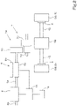
- FIG. 2 is a block diagram of a drive train of the electric vehicle 1.
- the electric vehicle 1 includes, as components of the drive train, a power transmission mechanism 7, at least one wheel brake 8, an electromagnetic brake 9, and a controller 10.
- the power transmission mechanism 7 is a mechanism that transmits the rotational power of the electric motor 6 to the wheels 5 (in the present embodiment, the rear wheels 5R).
- the power transmission mechanism 7 defines at least a part of the power transmission path between the electric motor 6 and the wheel 5.
- the power transmission path between the electric motor 6 and the wheel 5 includes the power transmission mechanism 7 and the electromagnetic brake 9.
- the power transmission mechanism 7 has a speed reducer 7A and a differential 7B.
- the rotational power of the electric motor 6 is input to the speed reducer 7A and transmitted to the wheels 5 via the differential 7B.
- the speed reducer 7A reduces the rotation speed of the electric motor 6 by using a combination of a plurality of gears 70 and transmits the rotational power to the differential 7B.
- the differential 7B is connected to an axle 15 of the wheels 5, and transmits the rotational power, which is transmitted from the speed reducer 7A, to the wheels 5 on the left side and the right side.
- the wheel brake 8 is provided on the wheel 5.
- the wheel brake 8 is provided, among the front wheels 5F and the rear wheels 5R, at least on each of the wheels that serves as a driving wheel.
- the wheel brake 8 is provided on each of the rear wheels 5R.
- the wheel brake 8 may be provided on each of the front wheels 5F or may be provided on each of the front wheels 5F and the rear wheels 5R.
- the wheel brake 8 is a brake that stops the rotation of the wheel 5 by using a frictional braking force.
- the wheel brake 8 has, for example, a brake disc that rotates together with the wheel 5, and a brake pad that is pressed against the brake disc by being driven by a hydraulic cylinder or the like.
- the wheel brake 8 is activated when a brake pedal, which is provided in the electric vehicle 1, is depressed.
- the electromagnetic brake 9 stops the rotation of the electric motor 6.
- the electromagnetic brake 9 is provided on a power transmission path between the electric motor 6 and the wheel 5 (at an intermediate position on a path along which power is transmitted from the electric motor 6 to the wheel 5).
- the electromagnetic brake 9 is provided on a power transmission path between the electric motor 6 and the power transmission mechanism 7 (at an intermediate position on a path along which power is transmitted from the electric motor 6 to the power transmission mechanism 7).
- the electromagnetic brake 9 is provided on a power transmission path between the electric motor 6 and the speed reducer 7A (at an intermediate position on a path along which power is transmitted from the electric motor 6 to the speed reducer 7A).
- the electromagnetic brake 9 stops the rotation of an output shaft 6a of the electric motor 6 (a shaft that transmits the rotational power of the electric motor 6 to the power transmission mechanism 7).
- the electromagnetic brake 9 is attached to the output shaft 6a of the electric motor 6.
- the electromagnetic brake 9 may be attached to another shaft 6b that rotates in coordination with the output shaft 6a of the electric motor 6.
- a shaft that protrudes in a direction away from the output shaft 6a of the electric motor 6 is illustrated as the other shaft 6b.
- the electromagnetic brake 9 has a rotary portion 9a, which is attached to the output shaft 6a (or the other shaft 6b) of the electric motor 6, and a fixed portion 9b, which faces the rotary portion 9a.
- the electromagnetic brake 9 can generate a braking force (a force that stops the rotation of the rotary portion 9a and the output shaft 6a) due to friction and magnetism by causing the rotary portion 9a and the fixed portion 9b to contact each other by using an electromagnetic force that is generated by energizing a coil.
- the electromagnetic brake 9 is activated based on control by the controller 10.
- the controller 10 includes a CPU, an electric-electronic circuit, a storage unit, and the like.
- the storage unit includes a RAM, a ROM, and the like.
- a predetermined control program is stored in the storage unit.
- the CPU controls the operations of the electric motor 6 and the electromagnetic brake 9 based on the control program.
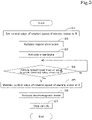
- FIG. 3 is a flowchart of an example (first example) of an operational flow when the electric vehicle 1 is stopped from a travelling state.
- the controller 10 sets the control value of the rotation speed of the electric motor 6 to 0 (S1).
- the phrase “sets the control value of the rotation speed of the electric motor 6 to 0” means that the controller 10 controls the value of an electric current supplied to the electric motor 6 so that the rotation speed of the electric motor 6 becomes 0. If the controller 10 sets the control value of the rotation speed of the electric motor 6 to 0 when the electric vehicle 1 is moving, an electric current for setting the rotation speed to 0 (an electric current that causes the electric motor 6 to rotate in a direction opposite to the direction in which the electric motor 6 is rotating) is supplied to the electric motor 6.
- the electric motor 6 enters a state in which the electric motor 6 is forcibly rotated in accordance with the rotation of the wheel 5, until the rotation speed becomes 0 (until the electric vehicle 1 stops). Thus, the electric motor 6 enters a regenerative state in which the electric motor 6 functions as a generator, and a regenerative brake is activated (S2). Thus, the electric vehicle 1 starts decelerating.
- the controller 10 starts the operation of setting the control value of the rotation speed of the electric motor 6 to 0 when an accelerator pedal, which is provided in the electric vehicle 1, is stopped being depressed or when the accelerator pedal is stopped being depressed and the brake pedal is depressed.
- the controller 10 After activating the regenerative brake, the controller 10 activates the wheel brake 8 when the brake pedal is depressed (S3). Because the electric vehicle 1 decelerates when the regenerative brake is activated, the wheel brake 8 is activated in a state in which the electric vehicle 1 has decelerated due to the activation of the regenerative brake.
- the electric vehicle 1 further decelerates due to activation of the wheel brake 8 in addition to the regenerative brake.
- the controller 10 maintains the control value of the rotation speed of the electric motor 6 at 0 (S5), and, while maintaining the control value at 0, activates the electromagnetic brake 9 (S6).
- the electric vehicle 1 stops travelling (S7).
- the controller 10 does not activate the electromagnetic brake 9 until the vehicle speed becomes the predetermined value close to 0.
- the "predetermined value close to 0" is, for example, "5 km/h”. However, the predetermined value is not limited to this value, may be a value (for example, "10 km/h") greater than this value, or may be a value (for example "3 km/h”) less than this value.
- the controller 10 can maintain the stopped state of the electric vehicle 1 by maintaining the control value of the rotation speed of the electric motor 6 at 0 and maintaining the activated state of the electromagnetic brake 9.
- the controller 10 releases the stopped state of the electric vehicle 1.
- the operation unit 16, which is operable by an operator sitting on the seat 4, is, for example, an accelerator pedal, an operation button, or the like.
- the controller 10 stops maintaining the control value of the rotation speed of the electric motor 6 at 0, and stops activating the electromagnetic brake 9.
- the electric vehicle 1 is released from the stopped state and becomes capable of travelling.
- the controller 10 maintains the control value of the rotation speed of the electric motor 6 at 0 and activates the electromagnetic brake 9.
- the controller 10 after setting the control value of the rotation speed of the electric motor 6 to 0 and activating the regenerative brake of the electric motor 6, maintains the control value of the rotation speed of the electric motor 6 at 0 and activates the electromagnetic brake 9 when the vehicle speed of the electric vehicle 1 becomes lower than or equal to the predetermined value close to 0.
- the controller 10 sets the control value of the rotation speed of the electric motor 6 to 0 and activates the regenerative brake of the electric motor 6, and, after the wheel brake 8 is activated, the controller 10 maintains the control value of the rotation speed of the electric motor 6 at 0 and activates the electromagnetic brake 9 when the vehicle speed of the electric vehicle 1 becomes lower than or equal a predetermined value close to 0.
- the controller 10 stops the electric vehicle 1 by maintaining the control value of the rotation speed of the electric motor 6 at 0 and activating the electromagnetic brake 9 when the vehicle speed becomes lower than or equal to a predetermined value close to 0. Therefore, it is possible to reduce heat generation and wear due to friction that occur when the electromagnetic brake 9 is activated.
- the controller 10 maintains the control value of the rotation speed of the electric motor 6 at 0 and maintains the activated state of the electromagnetic brake 9 after the electric vehicle 1 has stopped travelling. Therefore, it is possible to maintain the stopped state without continuing depressing the brake pedal or manually activating the parking brake as in existing electric vehicles.
- FIG. 4 is a flowchart of another example (second example) of an operational flow when the electric vehicle 1 is stopped from a travelling state.
- S1 to S5 are the same as those of the operational flow of the first example.
- the controller 10 sets the control value of the rotation speed of the electric motor 6 to 0 (S1).
- the control value of the rotation speed of the electric motor 6 is set to 0 in the travelling state, the electric motor 6 enters a state in which the electric motor 6 is forcibly rotated in accordance with the rotation of the wheel 5.
- the electric motor 6 functions as a generator, and a regenerative brake is activated (S2).
- the controller 10 After activating the regenerative brake, the controller 10 activates the wheel brake 8 when the brake pedal is depressed (S3). Because the electric vehicle 1 decelerates when the regenerative brake is activated, the wheel brake 8 is activated in a state in which the electric vehicle 1 has decelerated from the speed before activation of the regenerative brake.
- the electric vehicle 1 further decelerates due to activation of the wheel brake 8 in addition to the regenerative brake.
- the controller 10 maintains the control value of the rotation speed of the electric motor 6 at 0 (S5), and, while maintaining the control value at 0, activates the electromagnetic brake 9 (S7).
- the electric vehicle 1 stops travelling (S8).
- the controller 10 does not activate the electromagnetic brake 9 until the vehicle speed becomes the predetermined value close to 0.
- the temperature of the electric motor 6 or an electric device electrically connected to the electric motor 6 is considered as a condition for activating the electromagnetic brake 9.
- the electric device electrically connected to the electric motor 6, which is an electric device directly or indirectly electrically connected the electric motor 6, is, for example, a battery that supplies electric power to the electric motor 6, an inverter interposed between the battery and the electric motor 6, or the like.
- the battery or the inverter is mounted in the electric vehicle 1.
- the electric motor 6 or the electric device electrically connected to the electric motor 6 will be referred to as "the electric motor 6 or the like".
- the controller 10 while maintaining the control value of the rotation speed of the electric motor 6 at 0, activates the electromagnetic brake 9 when the temperature of the electric motor 6 or the like becomes higher than or equal to a predetermined temperature (S6: Yes). On the other hand, the controller 10 does not activate the electromagnetic brake 9 when the temperature of the electric motor 6 or the like is lower than the predetermined temperature (S6: No).
- the aforementioned predetermined temperature may be, for example, 100°C.
- the predetermined temperature is not limited be 100°C, may be a temperature lower than 100°C (for example, 80°C), or may be a temperature higher than 100°C (for example, 120°C).
- the predetermined temperature may be changed in accordance with the type of the electric motor 6 or the like whose temperature is considered as a condition for activating the electromagnetic brake 9.
- the predetermined temperature is set to, for example, 100°C.
- the predetermined temperature is set to, for example, 60°C.
- the predetermined temperature is set to, for example, 80°C.
- the predetermined temperature is not limited to any of these temperatures.
- the controller 10 receives, from the temperature-measuring device, information regarding the temperature of the electric motor 6 or the like, and, based on the information, determines whether the temperature of the electric motor 6 or the like is higher than or equal to the predetermined temperature.
- FIG. 5 is a flowchart of still another example (third example) of an operational flow when the electric vehicle 1 is stopped from a travelling state.
- S1 to S5 are the same as those of the operational flow of the first example.
- the controller 10 sets the control value of the rotation speed of the electric motor 6 to 0 (S1).
- the control value of the rotation speed of the electric motor 6 is set to 0 in the travelling state, the electric motor 6 enters a state in which the electric motor 6 is forcibly rotated in accordance with the rotation of the wheel 5.
- the electric motor 6 functions as a generator, and a regenerative brake is activated (S2).
- the controller 10 After activating the regenerative brake, the controller 10 activates the wheel brake 8 when the brake pedal is depressed (S3). Because the electric vehicle 1 decelerates when the regenerative brake is activated, the wheel brake 8 is activated in a state in which the electric vehicle 1 has decelerated from the speed before activation of the regenerative brake.
- the electric vehicle 1 further decelerates due to activation of the wheel brake 8 in addition to the regenerative brake.
- the controller 10 maintains the control value of the rotation speed of the electric motor 6 at 0 (S5), and, while maintaining the control value at 0, activates the electromagnetic brake 9 (S7).
- the electric vehicle 1 stops travelling (S8).
- the controller 10 does not activate the electromagnetic brake 9 until the vehicle speed becomes the predetermined value close to 0.
- a time for which the control value of the rotation speed of the electric motor 6 is maintained at 0 is considered as a condition for activating the electromagnetic brake 9.
- the controller 10 while maintaining the control value of the rotation speed of the electric motor 6 at 0, activates the electromagnetic brake 9 when a predetermined time elapses (S6: Yes).
- the controller 10 while maintain the control value of the rotation speed of the electric motor 6 at 0, does not activate the electromagnetic brake 9 when the predetermined does not elapse (S6: No).
- the aforementioned predetermined time may be, for example, 30 seconds.
- the predetermined time is not limited be 30 seconds, may be a time shorter than 30 seconds (for example, 20 seconds), or may be a time longer than 30 seconds (for example, 60 seconds).
- the controller 10 receives, from the time-measuring device, information regarding the time for which the rotation speed of the electric motor 6 is maintained at 0, and, based on the information, determines whether the predetermined time has elapsed while the control value of the rotation speed of the electric motor 6 is maintained at 0.
- the wheel brake 8 is activated by depressing the brake pedal.
- the wheel brake 8 may be activated by, instead of depressing the brake pedal, operating a brake operation unit different from the brake pedal (for example, a brake button or the like provided in the electric vehicle 1).
- the wheel brake 8 may be activated by the controller 10.
- FIG. 6 is a block diagram of another example of a drive train of the electric vehicle 1.
- the drive train illustrated in FIG. 6 includes a transmission shaft 11 that transmits the rotational power of the electric motor 6 to a moving unit 13 other than the wheel 5.
- the transmission shaft 11 is, for example, a power take-off (PTO) shaft.
- the moving unit 13 is a working device that is driven by power transmitted from the PTO shaft.
- the moving unit 13 is a working device that performs work on an agricultural field.
- the working device is, for example, a cultivator that cultivates the agricultural field, a broadcast spreader that spreads fertilizer and agricultural chemicals over the agricultural field, a seeder that spreads seeds over the agricultural field, or the like.
- a power branching unit 14 which branches the rotational power of the output shaft 6a and transmits the rotational power to the transmission shaft 11, is provided on the output shaft 6a of the electric motor 6.
- the power branching unit 14 includes, for example, a gear mechanism, a belt transmission mechanism, or the like.
- the clutch 12 is provided in an intermediate part of the power transmission path from the output shaft 6a to the transmission shaft 11.
- the clutch 12 is, for example, an electric clutch.
- a one-way clutch is preferably used as the clutch 12.
- the controller 10 when stopping movement of the moving unit 13, maintains the control value of the rotation speed of the electric motor 6 at 0 and activates the electromagnetic brake 9, and stops transmission of the rotational power from the electric motor 6 to the transmission shaft 11 by using the clutch 12.
- the controller 10 when stopping movement of the moving unit 13, maintains the control value of the rotation speed of the electric motor 6 at 0 and activates the electromagnetic brake 9, and stops transmission of the rotational power from the electric motor 6 to the transmission shaft 11 by using the clutch 12.
- the clutch 12 is not limited to a clutch that is activated by the controller 10.
- the clutch 12 may be, instead of a clutch activated by the controller 10, a clutch that can be activated by operating an operation actuator such as an operation button (by performing an operation for stopping transmission of the rotational power from the electric motor 6 to the transmission shaft 11).
- an operation actuator such as an operation button
- the electric vehicle 1 according to the embodiment described above has the following advantages.
- the electric vehicle 1 includes: the electric motor 6; the wheel 5 that is driven by the electric motor 6; the power transmission mechanism 7 that defines at least a part of the power transmission path between the electric motor 6 and the wheel 5 and that transmits rotational power of the electric motor 6 to the wheel 5; the wheel brake 8 that is provided on the wheel 5; the electromagnetic brake 9 that stops rotation of the electric motor 6; and the controller 10 that maintains a control value of the rotation speed of the electric motor 6 at 0 and activates the electromagnetic brake 9 when the vehicle speed becomes lower than or equal to a predetermined value close to 0.
- the controller 10 after setting the control value of the rotational speed of the electric motor 6 to 0 and activating the regenerative brake of the electric motor 6, maintains the control value at 0 and activates the electromagnetic brake 9 when the vehicle speed becomes lower than or equal to the predetermined value close to 0.
- the controller 10 after activating the wheel brake 8 and the regenerative brake, maintains the control value of the rotational speed of the electric motor 6 at 0 and activates the electromagnetic brake 9 when the vehicle speed becomes lower than or equal to the predetermined value close to 0.
- the controller 10 while maintaining the control value of the rotational speed of the electric motor 6 at 0, activates the electromagnetic brake 9 when the temperature of the electric motor 6 becomes higher than or equal to a predetermined temperature.
- the controller 10 while maintaining the control value of the rotational speed of the electric motor 6 at 0, activates the electromagnetic brake 9 when the temperature of an electric device electrically connected to the electric motor 6 becomes higher than or equal to a predetermined temperature.
- the controller 10 while maintaining the control value of the rotational speed of the electric motor 6 at 0, activates the electromagnetic brake 9 when a predetermined time elapses.
- the electromagnetic brake 9 is provided on the power transmission path between the electric motor 6 and the wheel 5.
- the electromagnetic brake 9 is provided on the power transmission path between the electric motor 6 and the power transmission mechanism 7.
- the electric vehicle 1 includes the transmission shaft 11 that transmits the rotational power of the electric motor 6 to the moving unit 13 other than the wheel 5; the clutch 12 that allows or prohibits transmission of the rotational power of the electric motor 6 is provided between an output shaft of the electric motor 6 and the transmission shaft 11; and the controller 10, when stopping movement of the moving unit 13, maintains the control value of the rotational speed of the electric motor 6 at 0 and activates the electromagnetic brake 9 and causes the clutch 12 to prohibit transmission of the rotational power.
- the electric vehicle 1 includes the operation unit 16 that is operated by an operator, and the controller 10 stops activation of the electromagnetic brake 9 when the operation unit 16 is operated.
Landscapes
- Engineering & Computer Science (AREA)
- Transportation (AREA)
- Mechanical Engineering (AREA)
- Chemical & Material Sciences (AREA)
- Combustion & Propulsion (AREA)
- Power Engineering (AREA)
- Physics & Mathematics (AREA)
- Electromagnetism (AREA)
- Electric Propulsion And Braking For Vehicles (AREA)
- Regulating Braking Force (AREA)
- Braking Arrangements (AREA)
Abstract
An electric vehicle (1) includes: an electric motor (6); a wheel (5) that is driven by the electric motor (6); a power transmission mechanism (7) that defines at least a part of a power transmission path between the electric motor (6) and the wheel (5) and that transmits rotational power of the electric motor (6) to the wheel (5); a wheel brake (8) that is provided on the wheel (5); an electromagnetic brake (9) that stops rotation of the electric motor (6); and a controller (10) that maintains a control value of a rotation speed of the electric motor (6) at 0 and activates the electromagnetic brake (9) when a vehicle speed becomes lower than or equal to a predetermined value close to 0.
Description
- The present invention relates to an electric vehicle that is driven by an electric motor.
- To date, an electric vehicle disclosed in
Japanese Unexamined Patent Application Publication No. 2011-223681 - In the electric vehicle described above, heat generation and wear of a brake pad due to friction occur when the brake is activated to stop the vehicle in a travelling state. In order to maintain a stopped state, it is necessary to continue depressing a brake pedal or to manually activate a parking brake. In a case where the electric vehicle is a four-wheel drive vehicle that brakes a wheel by pressing a brake disc by using an electric actuator, it is necessary to use two or more electric actuators.
- In consideration of these problems, an object of the present invention is to provide an electric vehicle that can reduce heat generation and wear due to friction that occur when a brake is activated, make it easy to maintain a stopped state, and reduce the number of electric actuators for brakes that stop the vehicle.
- Technical means used by the present invention to achieve the above object is featured in the following.
- An electric vehicle according to an aspect of the present invention includes: an electric motor; a wheel that is driven by the electric motor; a power transmission mechanism that defines at least a part of a power transmission path between the electric motor and the wheel and that transmits rotational power of the electric motor to the wheel; a wheel brake that is provided on the wheel; an electromagnetic brake that stops rotation of the electric motor; and a controller that maintains a control value of a rotation speed of the electric motor at 0 and activates the electromagnetic brake when a vehicle speed becomes lower than or equal to a predetermined value close to 0.
- The controller may, after setting the control value to 0 and activating a regenerative brake of the electric motor, maintain the control value at 0 and activate the electromagnetic brake when the vehicle speed becomes lower than or equal to the predetermined value.
- The controller may, after activating the wheel brake and the regenerative brake, maintain the control value at 0 and activate the electromagnetic brake when the vehicle speed becomes lower than or equal to the predetermined value.
- The controller may, while maintaining the control value at 0, activate the electromagnetic brake when a temperature of the electric motor becomes higher than or equal to a predetermined temperature.
- The controller may, while maintaining the control value at 0, activate the electromagnetic brake when a temperature of an electric device electrically connected to the electric motor becomes higher than or equal to a predetermined temperature.
- The controller may, while maintaining the control value at 0, activate the electromagnetic brake when a predetermined time elapses.
- The electromagnetic brake may be provided on the power transmission path between the electric motor and the wheel.
- The electromagnetic brake may be provided on a power transmission path between the electric motor and the power transmission mechanism.
- The electric vehicle may include a transmission shaft that transmits the rotational power of the electric motor to a moving unit other than the wheel; a clutch that allows or prohibits transmission of the rotational power may be provided between an output shaft of the electric motor and the transmission shaft; and the controller may, when stopping movement of the moving unit, maintain the control value at 0 and activates the electromagnetic brake and causes the clutch to prohibit transmission of the rotational power.
- The electric vehicle may include an operation unit that is operated by an operator, and the controller may stop activation of the electromagnetic brake when the operation unit is operated.
- With the electric vehicle according to the present invention, it is possible to stop the electric vehicle and to maintain the stopped state by maintaining the control value of the rotation speed of the electric motor at 0 and activating the electromagnetic brake when the vehicle speed becomes lower than or equal to the predetermined value close to 0. Therefore, it is possible to minimize deceleration due to friction of the brake (the electromagnetic brake), and to reduce heat generation and wear due to friction that occur when the brake is activated. Moreover, it is possible to maintain the stopped state without continuing depressing the brake pedal and without manually operating a parking brake. Furthermore, it is possible to reduce the number of electric actuators for brakes, because the electric actuator (the electromagnetic brake) is used not to press the brake disc but to stop rotation of the electric motor.
- A more complete appreciation of preferred embodiments of the present invention and many of the attendant advantages thereof will be readily obtained as the same becomes better understood by reference to the following detailed description when considered in connection with the accompanying drawings described below.
-
FIG. 1 is a side view of an embodiment of an electric vehicle according to the present invention. -
FIG. 2 is a block diagram of a drive train of the electric vehicle. -
FIG. 3 is a flowchart of an example (first example) of an operational flow when the electric vehicle is stopped from a travelling state. -
FIG. 4 is a flowchart of another example (second example) of an operational flow when the electric vehicle is stopped from a travelling state. -
FIG. 5 is a flowchart of still another example (third example) of an operational flow when the electric vehicle is stopped from a travelling state. -
FIG. 6 is a block diagram of another example of a drive train of the electric vehicle. - The preferred embodiments will now be described with reference to the accompanying drawings, wherein like reference numerals designate corresponding or identical elements throughout the various drawings. The drawings are to be viewed in an orientation in which the reference numerals are viewed correctly.
- Hereafter, preferred embodiments of an electric vehicle according to the present invention will be described.
-
FIG. 1 is a side view of an embodiment of anelectric vehicle 1 according to the present invention. - In
FIG. 1 , a working vehicle is illustrated as theelectric vehicle 1. The working vehicle illustrated inFIG. 1 is a tractor. However, theelectric vehicle 1 according to the present invention is not limited to a tractor. Theelectric vehicle 1 may be a working vehicle such as a backhoe, a loader working machine (a wheel loader, a compact truck loader, a skid-steer loader, or the like), a utility vehicle (a multipurpose working vehicle), a truck; or may be a vehicle other than a working vehicle. - The
electric vehicle 1 includes avehicle body 2 and atravel device 3 that supports thevehicle body 2 so that thevehicle body 2 can travel. - A
seat 4, on which an operator sits, is provided in thevehicle body 2. Thetravel device 3 includes at least onewheel 5. Thewheel 5 includes at least onefront wheel 5F that is provided on a front part of thevehicle body 2 and at least onerear wheel 5R that is provided on a rear part of thevehicle body 2. Thefront wheel 5F and therear wheel 5R are provided on each of the left side and the right side of thevehicle body 2. - An
electric motor 6, which drives at least one wheel of thetravel device 3, is mounted in thevehicle body 2. Theelectric vehicle 1 according to the present embodiment is a rear-wheel drive electric vehicle in which therear wheels 5R are driven by theelectric motor 6. However, theelectric vehicle 1 may be a front-wheel drive electric vehicle in which thefront wheels 5F are driven by theelectric motor 6, or may be a four-wheel drive electric vehicle in which thefront wheels 5F and therear wheels 5R are driven by theelectric motor 6. -
FIG. 2 is a block diagram of a drive train of theelectric vehicle 1. - As illustrated in
FIG. 2 , theelectric vehicle 1 includes, as components of the drive train, apower transmission mechanism 7, at least onewheel brake 8, anelectromagnetic brake 9, and acontroller 10. - The
power transmission mechanism 7 is a mechanism that transmits the rotational power of theelectric motor 6 to the wheels 5 (in the present embodiment, therear wheels 5R). Thepower transmission mechanism 7 defines at least a part of the power transmission path between theelectric motor 6 and thewheel 5. In the example illustrated inFIG. 2 , the power transmission path between theelectric motor 6 and thewheel 5 includes thepower transmission mechanism 7 and theelectromagnetic brake 9. - The
power transmission mechanism 7 has aspeed reducer 7A and a differential 7B. The rotational power of theelectric motor 6 is input to thespeed reducer 7A and transmitted to thewheels 5 via the differential 7B. Thespeed reducer 7A reduces the rotation speed of theelectric motor 6 by using a combination of a plurality ofgears 70 and transmits the rotational power to the differential 7B. The differential 7B is connected to anaxle 15 of thewheels 5, and transmits the rotational power, which is transmitted from thespeed reducer 7A, to thewheels 5 on the left side and the right side. - The
wheel brake 8 is provided on thewheel 5. Preferably, thewheel brake 8 is provided, among thefront wheels 5F and therear wheels 5R, at least on each of the wheels that serves as a driving wheel. In the present embodiment, thewheel brake 8 is provided on each of therear wheels 5R. However, thewheel brake 8 may be provided on each of thefront wheels 5F or may be provided on each of thefront wheels 5F and therear wheels 5R. Thewheel brake 8 is a brake that stops the rotation of thewheel 5 by using a frictional braking force. Thewheel brake 8 has, for example, a brake disc that rotates together with thewheel 5, and a brake pad that is pressed against the brake disc by being driven by a hydraulic cylinder or the like. Thewheel brake 8 is activated when a brake pedal, which is provided in theelectric vehicle 1, is depressed. - The
electromagnetic brake 9 stops the rotation of theelectric motor 6. Theelectromagnetic brake 9 is provided on a power transmission path between theelectric motor 6 and the wheel 5 (at an intermediate position on a path along which power is transmitted from theelectric motor 6 to the wheel 5). - In the present embodiment, the
electromagnetic brake 9 is provided on a power transmission path between theelectric motor 6 and the power transmission mechanism 7 (at an intermediate position on a path along which power is transmitted from theelectric motor 6 to the power transmission mechanism 7). To be specific, theelectromagnetic brake 9 is provided on a power transmission path between theelectric motor 6 and thespeed reducer 7A (at an intermediate position on a path along which power is transmitted from theelectric motor 6 to thespeed reducer 7A). - The
electromagnetic brake 9 stops the rotation of anoutput shaft 6a of the electric motor 6 (a shaft that transmits the rotational power of theelectric motor 6 to the power transmission mechanism 7). In the present embodiment, theelectromagnetic brake 9 is attached to theoutput shaft 6a of theelectric motor 6. However, theelectromagnetic brake 9 may be attached to anothershaft 6b that rotates in coordination with theoutput shaft 6a of theelectric motor 6. InFIG. 2 , a shaft that protrudes in a direction away from theoutput shaft 6a of theelectric motor 6 is illustrated as theother shaft 6b. - The
electromagnetic brake 9 has arotary portion 9a, which is attached to theoutput shaft 6a (or theother shaft 6b) of theelectric motor 6, and a fixedportion 9b, which faces therotary portion 9a. Theelectromagnetic brake 9 can generate a braking force (a force that stops the rotation of therotary portion 9a and theoutput shaft 6a) due to friction and magnetism by causing therotary portion 9a and the fixedportion 9b to contact each other by using an electromagnetic force that is generated by energizing a coil. - The
electromagnetic brake 9 is activated based on control by thecontroller 10. Thecontroller 10 includes a CPU, an electric-electronic circuit, a storage unit, and the like. The storage unit includes a RAM, a ROM, and the like. A predetermined control program is stored in the storage unit. The CPU controls the operations of theelectric motor 6 and theelectromagnetic brake 9 based on the control program. -
FIG. 3 is a flowchart of an example (first example) of an operational flow when theelectric vehicle 1 is stopped from a travelling state. - When stopping the
electric vehicle 1 from a travelling state, first, thecontroller 10 sets the control value of the rotation speed of theelectric motor 6 to 0 (S1). The phrase "sets the control value of the rotation speed of theelectric motor 6 to 0" means that thecontroller 10 controls the value of an electric current supplied to theelectric motor 6 so that the rotation speed of theelectric motor 6 becomes 0. If thecontroller 10 sets the control value of the rotation speed of theelectric motor 6 to 0 when theelectric vehicle 1 is moving, an electric current for setting the rotation speed to 0 (an electric current that causes theelectric motor 6 to rotate in a direction opposite to the direction in which theelectric motor 6 is rotating) is supplied to theelectric motor 6. Theelectric motor 6 enters a state in which theelectric motor 6 is forcibly rotated in accordance with the rotation of thewheel 5, until the rotation speed becomes 0 (until theelectric vehicle 1 stops). Thus, theelectric motor 6 enters a regenerative state in which theelectric motor 6 functions as a generator, and a regenerative brake is activated (S2). Thus, theelectric vehicle 1 starts decelerating. - The
controller 10 starts the operation of setting the control value of the rotation speed of theelectric motor 6 to 0 when an accelerator pedal, which is provided in theelectric vehicle 1, is stopped being depressed or when the accelerator pedal is stopped being depressed and the brake pedal is depressed. - After activating the regenerative brake, the
controller 10 activates thewheel brake 8 when the brake pedal is depressed (S3). Because theelectric vehicle 1 decelerates when the regenerative brake is activated, thewheel brake 8 is activated in a state in which theelectric vehicle 1 has decelerated due to the activation of the regenerative brake. - The
electric vehicle 1 further decelerates due to activation of thewheel brake 8 in addition to the regenerative brake. When the vehicle speed of theelectric vehicle 1 becomes a predetermined value close to 0 (S4: Yes), thecontroller 10 maintains the control value of the rotation speed of theelectric motor 6 at 0 (S5), and, while maintaining the control value at 0, activates the electromagnetic brake 9 (S6). Thus, theelectric vehicle 1 stops travelling (S7). When the vehicle speed of theelectric vehicle 1 does not become the predetermined value close to 0 (S4: No), thecontroller 10 does not activate theelectromagnetic brake 9 until the vehicle speed becomes the predetermined value close to 0. - The "predetermined value close to 0" is, for example, "5 km/h". However, the predetermined value is not limited to this value, may be a value (for example, "10 km/h") greater than this value, or may be a value (for example "3 km/h") less than this value.
- Even after the
electric vehicle 1 has stopped travelling (S7), thecontroller 10 can maintain the stopped state of theelectric vehicle 1 by maintaining the control value of the rotation speed of theelectric motor 6 at 0 and maintaining the activated state of theelectromagnetic brake 9. - When an operation unit 16 (see
FIG. 2 ) for releasing the stopped state is operated, thecontroller 10 releases the stopped state of theelectric vehicle 1. Theoperation unit 16, which is operable by an operator sitting on theseat 4, is, for example, an accelerator pedal, an operation button, or the like. When a releasing operation using the operation unit 16 (depressing of the accelerator pedal, pressing of the operation button, or the like) is performed, thecontroller 10 stops maintaining the control value of the rotation speed of theelectric motor 6 at 0, and stops activating theelectromagnetic brake 9. Thus, theelectric vehicle 1 is released from the stopped state and becomes capable of travelling. - As heretofore described, when the vehicle speed of the
electric vehicle 1 becomes lower than or equal to the predetermined value close to 0, thecontroller 10 maintains the control value of the rotation speed of theelectric motor 6 at 0 and activates theelectromagnetic brake 9. - To be specific, the
controller 10, after setting the control value of the rotation speed of theelectric motor 6 to 0 and activating the regenerative brake of theelectric motor 6, maintains the control value of the rotation speed of theelectric motor 6 at 0 and activates theelectromagnetic brake 9 when the vehicle speed of theelectric vehicle 1 becomes lower than or equal to the predetermined value close to 0. - To be more specific, the
controller 10 sets the control value of the rotation speed of theelectric motor 6 to 0 and activates the regenerative brake of theelectric motor 6, and, after thewheel brake 8 is activated, thecontroller 10 maintains the control value of the rotation speed of theelectric motor 6 at 0 and activates theelectromagnetic brake 9 when the vehicle speed of theelectric vehicle 1 becomes lower than or equal a predetermined value close to 0. - As described above, with the
electric vehicle 1 according to the present invention, it is possible to minimize deceleration of theelectric vehicle 1 due to friction of theelectromagnetic brake 9, because thecontroller 10 stops theelectric vehicle 1 by maintaining the control value of the rotation speed of theelectric motor 6 at 0 and activating theelectromagnetic brake 9 when the vehicle speed becomes lower than or equal to a predetermined value close to 0. Therefore, it is possible to reduce heat generation and wear due to friction that occur when theelectromagnetic brake 9 is activated. - Moreover, it is possible to maintain the stopped state of the
electric vehicle 1 because thecontroller 10 maintains the control value of the rotation speed of theelectric motor 6 at 0 and maintains the activated state of theelectromagnetic brake 9 after theelectric vehicle 1 has stopped travelling. Therefore, it is possible to maintain the stopped state without continuing depressing the brake pedal or manually activating the parking brake as in existing electric vehicles. -
FIG. 4 is a flowchart of another example (second example) of an operational flow when theelectric vehicle 1 is stopped from a travelling state. S1 to S5 are the same as those of the operational flow of the first example. - When stopping the
electric vehicle 1 from a travelling state, first, thecontroller 10 sets the control value of the rotation speed of theelectric motor 6 to 0 (S1). When the control value of the rotation speed of theelectric motor 6 is set to 0 in the travelling state, theelectric motor 6 enters a state in which theelectric motor 6 is forcibly rotated in accordance with the rotation of thewheel 5. Thus, theelectric motor 6 functions as a generator, and a regenerative brake is activated (S2). - After activating the regenerative brake, the
controller 10 activates thewheel brake 8 when the brake pedal is depressed (S3). Because theelectric vehicle 1 decelerates when the regenerative brake is activated, thewheel brake 8 is activated in a state in which theelectric vehicle 1 has decelerated from the speed before activation of the regenerative brake. - The
electric vehicle 1 further decelerates due to activation of thewheel brake 8 in addition to the regenerative brake. When the vehicle speed of theelectric vehicle 1 becomes a predetermined value close to 0 (S4: Yes), thecontroller 10 maintains the control value of the rotation speed of theelectric motor 6 at 0 (S5), and, while maintaining the control value at 0, activates the electromagnetic brake 9 (S7). Thus, theelectric vehicle 1 stops travelling (S8). When the vehicle speed of theelectric vehicle 1 does not become the predetermined value close to 0 (S4: No), thecontroller 10 does not activate theelectromagnetic brake 9 until the vehicle speed becomes the predetermined value close to 0. - In the operational flow of the second example, the temperature of the
electric motor 6 or an electric device electrically connected to theelectric motor 6 is considered as a condition for activating theelectromagnetic brake 9. The electric device electrically connected to theelectric motor 6, which is an electric device directly or indirectly electrically connected theelectric motor 6, is, for example, a battery that supplies electric power to theelectric motor 6, an inverter interposed between the battery and theelectric motor 6, or the like. The battery or the inverter is mounted in theelectric vehicle 1. Hereafter, "theelectric motor 6 or the electric device electrically connected to theelectric motor 6" will be referred to as "theelectric motor 6 or the like". - As illustrated in
FIG. 4 , thecontroller 10, while maintaining the control value of the rotation speed of theelectric motor 6 at 0, activates theelectromagnetic brake 9 when the temperature of theelectric motor 6 or the like becomes higher than or equal to a predetermined temperature (S6: Yes). On the other hand, thecontroller 10 does not activate theelectromagnetic brake 9 when the temperature of theelectric motor 6 or the like is lower than the predetermined temperature (S6: No). - If the control value of the rotation speed of the
electric motor 6 is maintained at 0 when theelectric vehicle 1 is moving, an electric current for setting the rotation speed to 0 is continued to be supplied to theelectric motor 6 while theelectric motor 6 is forcibly rotated. Therefore, as time elapses while the control value of the rotation speed of theelectric motor 6 is maintained at 0, the temperature of theelectric motor 6 or the like increases because the electric current is continued to be supplied. - As a measure against this, by activating the
electromagnetic brake 9 when the temperature of theelectric motor 6 or the like becomes higher than or equal to a predetermined temperature while the control value of the rotation speed of theelectric motor 6 is maintained at 0, it is possible to reduce the amount of electric current suppled to set the rotation speed of theelectric motor 6 to 0 and it is possible to prevent overheating of theelectric motor 6 or the like. - The aforementioned predetermined temperature may be, for example, 100°C. However, the predetermined temperature is not limited be 100°C, may be a temperature lower than 100°C (for example, 80°C), or may be a temperature higher than 100°C (for example, 120°C).
- The predetermined temperature may be changed in accordance with the type of the
electric motor 6 or the like whose temperature is considered as a condition for activating theelectromagnetic brake 9. In a case where theelectric motor 6 or the like is theelectric motor 6, the predetermined temperature is set to, for example, 100°C. When theelectric motor 6 or the like is a battery, the predetermined temperature is set to, for example, 60°C. When theelectric motor 6 or the like is an inverter, the predetermined temperature is set to, for example, 80°C. However, the predetermined temperature is not limited to any of these temperatures. - It is possible to measure the temperature of the
electric motor 6 or the like by using a temperature-measuring device, such as a temperature sensor, included in theelectric vehicle 1. Thecontroller 10 receives, from the temperature-measuring device, information regarding the temperature of theelectric motor 6 or the like, and, based on the information, determines whether the temperature of theelectric motor 6 or the like is higher than or equal to the predetermined temperature. -
FIG. 5 is a flowchart of still another example (third example) of an operational flow when theelectric vehicle 1 is stopped from a travelling state. S1 to S5 are the same as those of the operational flow of the first example. - When stopping the
electric vehicle 1 from a travelling state, first, thecontroller 10 sets the control value of the rotation speed of theelectric motor 6 to 0 (S1). When the control value of the rotation speed of theelectric motor 6 is set to 0 in the travelling state, theelectric motor 6 enters a state in which theelectric motor 6 is forcibly rotated in accordance with the rotation of thewheel 5. Thus, theelectric motor 6 functions as a generator, and a regenerative brake is activated (S2). - After activating the regenerative brake, the
controller 10 activates thewheel brake 8 when the brake pedal is depressed (S3). Because theelectric vehicle 1 decelerates when the regenerative brake is activated, thewheel brake 8 is activated in a state in which theelectric vehicle 1 has decelerated from the speed before activation of the regenerative brake. - The
electric vehicle 1 further decelerates due to activation of thewheel brake 8 in addition to the regenerative brake. When the vehicle speed of theelectric vehicle 1 becomes a predetermined value close to 0 (S4: Yes), thecontroller 10 maintains the control value of the rotation speed of theelectric motor 6 at 0 (S5), and, while maintaining the control value at 0, activates the electromagnetic brake 9 (S7). Thus, theelectric vehicle 1 stops travelling (S8). When the vehicle speed of theelectric vehicle 1 does not become the predetermined value close to 0 (S4: No), thecontroller 10 does not activate theelectromagnetic brake 9 until the vehicle speed becomes the predetermined value close to 0. - In the operational flow of the third example, a time for which the control value of the rotation speed of the
electric motor 6 is maintained at 0 is considered as a condition for activating theelectromagnetic brake 9. - To be specific, the
controller 10, while maintaining the control value of the rotation speed of theelectric motor 6 at 0, activates theelectromagnetic brake 9 when a predetermined time elapses (S6: Yes). On the other hand, thecontroller 10, while maintain the control value of the rotation speed of theelectric motor 6 at 0, does not activate theelectromagnetic brake 9 when the predetermined does not elapse (S6: No). - As described above, as time elapses while the control value of the rotation speed of the
electric motor 6 is maintained at 0, the temperature of theelectric motor 6 or the like increases because the electric current is continued to be supplied. - Therefore, by activating the
electromagnetic brake 9 when the predetermined time elapses while the control value of the rotation speed of theelectric motor 6 or the like is maintained at 0, it is possible to reduce the amount of electric current suppled to set the rotation speed of theelectric motor 6 to 0, and it is possible to prevent overheating of theelectric motor 6 or the like. - The aforementioned predetermined time may be, for example, 30 seconds. However, the predetermined time is not limited be 30 seconds, may be a time shorter than 30 seconds (for example, 20 seconds), or may be a time longer than 30 seconds (for example, 60 seconds).
- It is possible to measure the time, for which the rotation speed of the
electric motor 6 is maintained at 0, by using a time-measuring device such as a timer included in theelectric vehicle 1. Thecontroller 10 receives, from the time-measuring device, information regarding the time for which the rotation speed of theelectric motor 6 is maintained at 0, and, based on the information, determines whether the predetermined time has elapsed while the control value of the rotation speed of theelectric motor 6 is maintained at 0. - In the first to third examples described above, it has been described that the
wheel brake 8 is activated by depressing the brake pedal. However, thewheel brake 8 may be activated by, instead of depressing the brake pedal, operating a brake operation unit different from the brake pedal (for example, a brake button or the like provided in the electric vehicle 1). Thewheel brake 8 may be activated by thecontroller 10. -
FIG. 6 is a block diagram of another example of a drive train of theelectric vehicle 1. - Hereafter, the difference between the configuration of the drive train illustrated in
FIG. 6 and the configuration of the drive train illustrated inFIG. 2 will be described, and the description of matters common to these configurations will be omitted. - The drive train illustrated in
FIG. 6 includes atransmission shaft 11 that transmits the rotational power of theelectric motor 6 to a movingunit 13 other than thewheel 5. Thetransmission shaft 11 is, for example, a power take-off (PTO) shaft. In this case, the movingunit 13 is a working device that is driven by power transmitted from the PTO shaft. In a case where theelectric vehicle 1 is a tractor, the movingunit 13 is a working device that performs work on an agricultural field. To be specific, the working device is, for example, a cultivator that cultivates the agricultural field, a broadcast spreader that spreads fertilizer and agricultural chemicals over the agricultural field, a seeder that spreads seeds over the agricultural field, or the like. - A
power branching unit 14, which branches the rotational power of theoutput shaft 6a and transmits the rotational power to thetransmission shaft 11, is provided on theoutput shaft 6a of theelectric motor 6. Thepower branching unit 14 includes, for example, a gear mechanism, a belt transmission mechanism, or the like. - A clutch 12, which allows or prohibits transmission of the rotational power from the
electric motor 6 to thetransmission shaft 11, is provided between theoutput shaft 6a of theelectric motor 6 and thetransmission shaft 11. The clutch 12 is provided in an intermediate part of the power transmission path from theoutput shaft 6a to thetransmission shaft 11. The clutch 12 is, for example, an electric clutch. In a case where thetransmission shaft 11 is a PTO shaft, a one-way clutch is preferably used as the clutch 12. - The
controller 10, when stopping movement of the movingunit 13, maintains the control value of the rotation speed of theelectric motor 6 at 0 and activates theelectromagnetic brake 9, and stops transmission of the rotational power from theelectric motor 6 to thetransmission shaft 11 by using the clutch 12. Thus, it is possible to stop both of thewheel 5 and the movingunit 13. Moreover, it is possible to stop the movement of the movingunit 13 before thewheel 5 stops by using the clutch 12. Therefore, it is possible to rapidly and reliably stop the movingunit 13. - The clutch 12 is not limited to a clutch that is activated by the
controller 10. The clutch 12 may be, instead of a clutch activated by thecontroller 10, a clutch that can be activated by operating an operation actuator such as an operation button (by performing an operation for stopping transmission of the rotational power from theelectric motor 6 to the transmission shaft 11). In this case, it is possible to stop the movement of the movingunit 13 independently from the movement of thewheel 5 by operating the operation actuator. That is, it is possible to stop the movingunit 13 by operating the operation actuator without stopping thewheel 5. - The
electric vehicle 1 according to the embodiment described above has the following advantages. - The
electric vehicle 1 includes: theelectric motor 6; thewheel 5 that is driven by theelectric motor 6; thepower transmission mechanism 7 that defines at least a part of the power transmission path between theelectric motor 6 and thewheel 5 and that transmits rotational power of theelectric motor 6 to thewheel 5; thewheel brake 8 that is provided on thewheel 5; theelectromagnetic brake 9 that stops rotation of theelectric motor 6; and thecontroller 10 that maintains a control value of the rotation speed of theelectric motor 6 at 0 and activates theelectromagnetic brake 9 when the vehicle speed becomes lower than or equal to a predetermined value close to 0. - With this configuration, it is possible to stop the
electric vehicle 1 and to maintain the stopped state by maintaining the control value of the rotation speed of theelectric motor 6 at 0 and activating theelectromagnetic brake 9 when the vehicle speed of theelectric vehicle 1 becomes lower than or equal to the predetermined value close to 0. Therefore, it is possible to minimize deceleration due to friction of the brake (the electromagnetic brake 9), and to reduce heat generation and wear due to friction that occur when the brake is activated. Moreover, it is possible to maintain the stopped state without continuing depressing the brake pedal and without manually operating a parking brake as in existing electric vehicles. Furthermore, it is possible to reduce the number of electric actuators for brakes, because the electric actuator (the electromagnetic brake 9) is used not to press the brake disc but to stop rotation of theelectric motor 6. - The
controller 10, after setting the control value of the rotational speed of theelectric motor 6 to 0 and activating the regenerative brake of theelectric motor 6, maintains the control value at 0 and activates theelectromagnetic brake 9 when the vehicle speed becomes lower than or equal to the predetermined value close to 0. - With this configuration, irrespective of whether the
wheel brake 8 is activated, it is possible to activate theelectromagnetic brake 9 after reducing the vehicle speed of theelectric vehicle 1 to the predetermined value close to 0 by using the regenerative brake of theelectric motor 6. - The
controller 10, after activating thewheel brake 8 and the regenerative brake, maintains the control value of the rotational speed of theelectric motor 6 at 0 and activates theelectromagnetic brake 9 when the vehicle speed becomes lower than or equal to the predetermined value close to 0. - With this configuration, it is possible to activate the
electromagnetic brake 9 after rapidly reducing the vehicle speed of theelectric vehicle 1 to the predetermined value close to 0 by activating thewheel brake 8 and the regenerative brake. - The
controller 10, while maintaining the control value of the rotational speed of theelectric motor 6 at 0, activates theelectromagnetic brake 9 when the temperature of theelectric motor 6 becomes higher than or equal to a predetermined temperature. - With this configuration, it is possible to prevent overheating of the
electric motor 6, which may occur if the control value of the rotation speed of theelectric motor 6 is continued to be maintained at 0 (an electric current for setting the rotation speed to 0 is continued to be caused to flow) while theelectric motor 6 is rotating. - The
controller 10, while maintaining the control value of the rotational speed of theelectric motor 6 at 0, activates theelectromagnetic brake 9 when the temperature of an electric device electrically connected to theelectric motor 6 becomes higher than or equal to a predetermined temperature. - With this configuration, it is possible to prevent overheating of the electric device electrically connected to the electric motor 6 (for example, a battery, an inverter, or the like), which may occur if the control value of the rotation speed of the
electric motor 6 is continued to be maintained at 0 (an electric current for setting the rotation speed to 0 is continued to be caused to flow) while theelectric motor 6 is rotating. - The
controller 10, while maintaining the control value of the rotational speed of theelectric motor 6 at 0, activates theelectromagnetic brake 9 when a predetermined time elapses. - With this configuration, it is possible to prevent overheating of the
electric motor 6 by reducing the time for which the control value of the rotation speed of theelectric motor 6 is continued to be maintained at 0 (an electric current for setting the rotation speed to 0 is continued to be caused to flow) while theelectric motor 6 is rotating. - The
electromagnetic brake 9 is provided on the power transmission path between theelectric motor 6 and thewheel 5. - With this configuration, it is possible to stop the rotation of the
electric motor 6 by using theelectromagnetic brake 9 at an intermediate position on the path along which power is transmitted from theelectric motor 6 to thewheel 5. - The
electromagnetic brake 9 is provided on the power transmission path between theelectric motor 6 and thepower transmission mechanism 7. - With this configuration, it is possible to stop the rotation of the
electric motor 6 by using theelectromagnetic brake 9 at an intermediate position on the path along which power is transmitted from theelectric motor 6 to thepower transmission mechanism 7. Therefore, it is possible to provide theelectromagnetic brake 9 at a position separated from thewheel 5. - The
electric vehicle 1 includes thetransmission shaft 11 that transmits the rotational power of theelectric motor 6 to the movingunit 13 other than thewheel 5; the clutch 12 that allows or prohibits transmission of the rotational power of theelectric motor 6 is provided between an output shaft of theelectric motor 6 and thetransmission shaft 11; and thecontroller 10, when stopping movement of the movingunit 13, maintains the control value of the rotational speed of theelectric motor 6 at 0 and activates theelectromagnetic brake 9 and causes the clutch 12 to prohibit transmission of the rotational power. - With this configuration, it is possible to stop both of the
wheel 5 and the movingunit 13 by using thecontroller 10. Moreover, it is possible to stop the movement of the movingunit 13 before thewheel 5 stops by using the clutch 12. Therefore, it is possible to rapidly and reliably stop the movingunit 13. - The
electric vehicle 1 includes theoperation unit 16 that is operated by an operator, and thecontroller 10 stops activation of theelectromagnetic brake 9 when theoperation unit 16 is operated. - With this configuration, it is possible for the operator to release the stopped state of the
electric vehicle 1 and to allow theelectric vehicle 1 to travel by operating theoperation unit 16. - While preferred embodiments of the present invention have been described above, it is to be understood that variations and modifications will be apparent to those skilled in the art without departing from the scope of the present invention. The scope of the present invention, therefore, is to be determined solely by the following claims.
Claims (10)
- An electric vehicle (1) comprising:an electric motor (6);a wheel (5) adapted to be driven by the electric motor (6);a power transmission mechanism (7) configured to define at least a part of a power transmission path between the electric motor (6) and the wheel (5) and that transmits rotational power of the electric motor (6) to the wheel (5);a wheel brake (8) that is provided on the wheel (5);an electromagnetic brake (9) configured to stop rotation of the electric motor (6); anda controller (10) configured to maintain a control value of a rotation speed of the electric motor (6) at 0 and to activate the electromagnetic brake (9) when a vehicle speed becomes lower than or equal to a predetermined value close to 0.
- The electric vehicle (1) according to claim 1, wherein the controller (10) is configured to, after setting the control value to 0 and activating a regenerative brake of the electric motor (6), maintain the control value at 0 and to activate the electromagnetic brake (9) when the vehicle speed becomes lower than or equal to the predetermined value.
- The electric vehicle (1) according to claim 2, wherein the controller (10) is configured to, after activating the wheel brake (8) and the regenerative brake, maintain the control value at 0 and to activate the electromagnetic brake (9) when the vehicle speed becomes lower than or equal to the predetermined value.
- The electric vehicle (1) according to any one of claims 1 to 3, wherein the controller (10) is configured to, while maintaining the control value at 0, activate the electromagnetic brake (9) when a temperature of the electric motor (6) becomes higher than or equal to a predetermined temperature.
- The electric vehicle (1) according to any one of claims 1 to 3, wherein the controller (10) is configured to, while maintaining the control value at 0, activate the electromagnetic brake (9) when a temperature of an electric device electrically connected to the electric motor (6) becomes higher than or equal to a predetermined temperature.
- The electric vehicle (1) according to any one of claims 1 to 3, wherein the controller (10) is configured to, while maintaining the control value at 0, activate the electromagnetic brake (9) when a predetermined time elapses.
- The electric vehicle (1) according to any one of claims 1 to 6, wherein the electromagnetic brake (9) is provided on the power transmission path between the electric motor (6) and the wheel (5).
- The electric vehicle (1) according to claim 7, wherein the electromagnetic brake (9) is provided on a power transmission path between the electric motor (6) and the power transmission mechanism (7).
- The electric vehicle (1) according to any one of claims 1 to 8, comprising:a transmission shaft (11) configured to transmit the rotational power of the electric motor (6) to a moving unit (13) other than the wheel (5),wherein a clutch (12) configured to allow or prohibit transmission of the rotational power is provided between an output shaft of the electric motor (6) and the transmission shaft (11), andwherein the controller (10) is configured to, when stopping movement of the moving unit (13), maintain the control value at 0, to activate the electromagnetic brake (9) and to cause the clutch (12) to prohibit transmission of the rotational power.
- The electric vehicle (1) according to any one of claims 1 to 9, comprising:an operation unit (16) configured to be operated by an operator,wherein the controller (10) is configured to stop activation of the electromagnetic brake (9) when the operation unit (16) is operated.
Applications Claiming Priority (1)
| Application Number | Priority Date | Filing Date | Title |
|---|---|---|---|
| JP2021083296A JP7489354B2 (en) | 2021-05-17 | 2021-05-17 | Electric vehicles |
Publications (1)
| Publication Number | Publication Date |
|---|---|
| EP4091858A1 true EP4091858A1 (en) | 2022-11-23 |
Family
ID=81654582
Family Applications (1)
| Application Number | Title | Priority Date | Filing Date |
|---|---|---|---|
| EP22173587.1A Pending EP4091858A1 (en) | 2021-05-17 | 2022-05-16 | Electric vehicle |
Country Status (3)
| Country | Link |
|---|---|
| US (1) | US12090842B2 (en) |
| EP (1) | EP4091858A1 (en) |
| JP (2) | JP7489354B2 (en) |
Families Citing this family (2)
| Publication number | Priority date | Publication date | Assignee | Title |
|---|---|---|---|---|
| KR20240075002A (en) * | 2022-11-16 | 2024-05-29 | 현대자동차주식회사 | Minimization Device Of Motor Heat and Minimization Method Thereof |
| JP2025025308A (en) | 2023-08-09 | 2025-02-21 | 株式会社クボタ | Electric vehicles |
Citations (6)
| Publication number | Priority date | Publication date | Assignee | Title |
|---|---|---|---|---|
| JPS5893403A (en) * | 1981-11-27 | 1983-06-03 | Hitachi Ltd | Regenerative braking control device for electric vehicles |
| JPS6046701A (en) * | 1983-09-26 | 1985-03-13 | Sanyo Electric Co Ltd | Motor-driven vehicle |
| JP2011223681A (en) | 2010-04-06 | 2011-11-04 | Toyota Motor Corp | Controller of regenerative braking torque |
| US20180244158A1 (en) * | 2015-08-26 | 2018-08-30 | Nissan Motor Co., Ltd. | Control method and control device for electric vehicle |
| JP2019075888A (en) * | 2017-10-16 | 2019-05-16 | 株式会社クボタ | Electric traveling vehicle |
| US20200317060A1 (en) * | 2016-05-25 | 2020-10-08 | Jaguar Land Rover Limited | Apparatus, system and method for braking |
Family Cites Families (6)
| Publication number | Priority date | Publication date | Assignee | Title |
|---|---|---|---|---|
| JPS6055804A (en) * | 1983-09-05 | 1985-04-01 | Agency Of Ind Science & Technol | Dynamic drive device |
| JP4420191B2 (en) * | 2003-10-30 | 2010-02-24 | 三菱自動車工業株式会社 | Electric car |
| JP2006117220A (en) * | 2004-09-27 | 2006-05-11 | Shin Kobe Electric Mach Co Ltd | Drum brake control system for autonomous vehicles |
| JP4238808B2 (en) * | 2004-09-30 | 2009-03-18 | 新神戸電機株式会社 | Autonomous vehicle braking system |
| JP2008148816A (en) * | 2006-12-15 | 2008-07-03 | Shin Kobe Electric Mach Co Ltd | Brake control system for electromagnetic induction golf cart |
| US10850622B2 (en) | 2017-10-16 | 2020-12-01 | Kubota Corporation | Electric travelling vehicle and grass mower |
-
2021
- 2021-05-17 JP JP2021083296A patent/JP7489354B2/en active Active
-
2022
- 2022-05-12 US US17/742,687 patent/US12090842B2/en active Active
- 2022-05-16 EP EP22173587.1A patent/EP4091858A1/en active Pending
-
2024
- 2024-05-13 JP JP2024077995A patent/JP7815322B2/en active Active
Patent Citations (6)
| Publication number | Priority date | Publication date | Assignee | Title |
|---|---|---|---|---|
| JPS5893403A (en) * | 1981-11-27 | 1983-06-03 | Hitachi Ltd | Regenerative braking control device for electric vehicles |
| JPS6046701A (en) * | 1983-09-26 | 1985-03-13 | Sanyo Electric Co Ltd | Motor-driven vehicle |
| JP2011223681A (en) | 2010-04-06 | 2011-11-04 | Toyota Motor Corp | Controller of regenerative braking torque |
| US20180244158A1 (en) * | 2015-08-26 | 2018-08-30 | Nissan Motor Co., Ltd. | Control method and control device for electric vehicle |
| US20200317060A1 (en) * | 2016-05-25 | 2020-10-08 | Jaguar Land Rover Limited | Apparatus, system and method for braking |
| JP2019075888A (en) * | 2017-10-16 | 2019-05-16 | 株式会社クボタ | Electric traveling vehicle |
Non-Patent Citations (1)
| Title |
|---|
| ALEX ROUSE: "Reverse Current Braking: Understanding Plugging for Electric Motors - AMBI-Tech Brakes", 3 December 2020 (2020-12-03), pages 1 - 4, XP093323615, Retrieved from the Internet <URL:https://www.ambitechbrakes.com/reverse-current-braking-understanding-plugging-for-electric-motors/> [retrieved on 20251009] * |
Also Published As
| Publication number | Publication date |
|---|---|
| JP7815322B2 (en) | 2026-02-17 |
| US12090842B2 (en) | 2024-09-17 |
| JP7489354B2 (en) | 2024-05-23 |
| US20220363127A1 (en) | 2022-11-17 |
| JP2024097964A (en) | 2024-07-19 |
| JP2022176727A (en) | 2022-11-30 |
Similar Documents
| Publication | Publication Date | Title |
|---|---|---|
| JP7815322B2 (en) | electric work vehicle | |
| US8597145B2 (en) | Torque transfer unit with integrated electric drive motor | |
| US6619460B1 (en) | Braking arrangement and braking maneuver means | |
| EP4048921B1 (en) | A transmission assembly | |
| WO2013115355A1 (en) | Vehicle control device | |
| US20240075818A1 (en) | Braking system of a motor vehicle and method for controlling the same | |
| EP4144568B1 (en) | Work vehicle | |
| US11731506B2 (en) | Driving system of electric vehicle | |
| JP2004350475A (en) | Work vehicle transmission | |
| US7618101B2 (en) | Brake system for automobile | |
| JP4049598B2 (en) | Driving force transmission device for four-wheel drive vehicle | |
| JP2020131717A (en) | Electric brake device | |
| JP2022505225A (en) | Transmission control device for agricultural work vehicles and transmission control method for agricultural work vehicles | |
| JP7167740B2 (en) | brake system | |
| JP3592401B2 (en) | Brake devices for agricultural work vehicles such as tractors | |
| JP3245413B2 (en) | Travel drive control device for tractor | |
| JP3714797B2 (en) | Power steering device | |
| JP4981463B2 (en) | Driving transmission structure of work vehicle | |
| JP3675409B2 (en) | Mobile farm machine | |
| KR20240038578A (en) | Agricultural working vehicle and method for controlling the same | |
| JP2025151436A (en) | Work vehicles | |
| JP3080514B2 (en) | Brake device for passenger work equipment | |
| JP3080789B2 (en) | Passenger work vehicle | |
| JP2023037146A (en) | Control device of work vehicle | |
| JPH02175438A (en) | Clutch control device of tractor, etc. |
Legal Events
| Date | Code | Title | Description |
|---|---|---|---|
| PUAI | Public reference made under article 153(3) epc to a published international application that has entered the european phase |
Free format text: ORIGINAL CODE: 0009012 |
|
| STAA | Information on the status of an ep patent application or granted ep patent |
Free format text: STATUS: REQUEST FOR EXAMINATION WAS MADE |
|
| 17P | Request for examination filed |
Effective date: 20220516 |
|
| AK | Designated contracting states |
Kind code of ref document: A1 Designated state(s): AL AT BE BG CH CY CZ DE DK EE ES FI FR GB GR HR HU IE IS IT LI LT LU LV MC MK MT NL NO PL PT RO RS SE SI SK SM TR |
|
| STAA | Information on the status of an ep patent application or granted ep patent |
Free format text: STATUS: EXAMINATION IS IN PROGRESS |
|
| 17Q | First examination report despatched |
Effective date: 20251016 |