EP4091784A1 - Kleiderbehandlungsvorrichtung mit einem schubladenpaneel - Google Patents
Kleiderbehandlungsvorrichtung mit einem schubladenpaneel Download PDFInfo
- Publication number
- EP4091784A1 EP4091784A1 EP22168868.2A EP22168868A EP4091784A1 EP 4091784 A1 EP4091784 A1 EP 4091784A1 EP 22168868 A EP22168868 A EP 22168868A EP 4091784 A1 EP4091784 A1 EP 4091784A1
- Authority
- EP
- European Patent Office
- Prior art keywords
- treating device
- clothes treating
- drawer panel
- demolding direction
- rear surface
- Prior art date
- Legal status (The legal status is an assumption and is not a legal conclusion. Google has not performed a legal analysis and makes no representation as to the accuracy of the status listed.)
- Pending
Links
- 238000005034 decoration Methods 0.000 claims abstract description 7
- 230000002452 interceptive effect Effects 0.000 claims description 17
- 238000001746 injection moulding Methods 0.000 claims description 12
- 239000007787 solid Substances 0.000 claims description 9
- 238000005192 partition Methods 0.000 claims description 7
- 230000000994 depressogenic effect Effects 0.000 claims description 4
- 238000004519 manufacturing process Methods 0.000 description 26
- 238000010586 diagram Methods 0.000 description 8
- 238000005406 washing Methods 0.000 description 2
- 230000004308 accommodation Effects 0.000 description 1
- 238000009825 accumulation Methods 0.000 description 1
- 230000001419 dependent effect Effects 0.000 description 1
- 239000003599 detergent Substances 0.000 description 1
- 238000001035 drying Methods 0.000 description 1
- 230000000694 effects Effects 0.000 description 1
- XLYOFNOQVPJJNP-UHFFFAOYSA-N water Substances O XLYOFNOQVPJJNP-UHFFFAOYSA-N 0.000 description 1
Images







Classifications
-
- B—PERFORMING OPERATIONS; TRANSPORTING
- B29—WORKING OF PLASTICS; WORKING OF SUBSTANCES IN A PLASTIC STATE IN GENERAL
- B29C—SHAPING OR JOINING OF PLASTICS; SHAPING OF MATERIAL IN A PLASTIC STATE, NOT OTHERWISE PROVIDED FOR; AFTER-TREATMENT OF THE SHAPED PRODUCTS, e.g. REPAIRING
- B29C45/00—Injection moulding, i.e. forcing the required volume of moulding material through a nozzle into a closed mould; Apparatus therefor
- B29C45/17—Component parts, details or accessories; Auxiliary operations
- B29C45/40—Removing or ejecting moulded articles
-
- D—TEXTILES; PAPER
- D06—TREATMENT OF TEXTILES OR THE LIKE; LAUNDERING; FLEXIBLE MATERIALS NOT OTHERWISE PROVIDED FOR
- D06F—LAUNDERING, DRYING, IRONING, PRESSING OR FOLDING TEXTILE ARTICLES
- D06F39/00—Details of washing machines not specific to a single type of machines covered by groups D06F9/00 - D06F27/00
- D06F39/02—Devices for adding soap or other washing agents
-
- B—PERFORMING OPERATIONS; TRANSPORTING
- B29—WORKING OF PLASTICS; WORKING OF SUBSTANCES IN A PLASTIC STATE IN GENERAL
- B29L—INDEXING SCHEME ASSOCIATED WITH SUBCLASS B29C, RELATING TO PARTICULAR ARTICLES
- B29L2031/00—Other particular articles
- B29L2031/762—Household appliances
-
- D—TEXTILES; PAPER
- D06—TREATMENT OF TEXTILES OR THE LIKE; LAUNDERING; FLEXIBLE MATERIALS NOT OTHERWISE PROVIDED FOR
- D06F—LAUNDERING, DRYING, IRONING, PRESSING OR FOLDING TEXTILE ARTICLES
- D06F39/00—Details of washing machines not specific to a single type of machines covered by groups D06F9/00 - D06F27/00
- D06F39/12—Casings; Tubs
Definitions
- the invention relates to a clothes treating device including a drawer panel.
- FIG. 1 is a schematic rear view of a drawer panel of an existing clothes treating device.
- the integral component is disadvantageous when a certain portion of the drawer panel needs to be replaced, for example, the integral component can only be replaced as a whole but cannot be partially replaced, thus causing high replacement cost and inconvenient operation.
- a demolding direction of the drawer panel may be provided with two opposite faces interfering with the demolding direction, so that the drawer panel requires mold sliders during injection molding and demolding, so that a mold and a manufacturing process of the drawer panel are complex.
- FIG. 2 and FIG. 3 are respectively schematic cross-sectional views of the drawer panel in FIG. 1 along lines D-D and E-E in a manufacturing process.
- a demolding direction A3 of a drawer panel 11 is provided with two opposite faces 33 and 35 interfering with A3, so that the drawer panel 11 requires a first slider 37 and a second slider 39 during injection molding and demolding.
- the first slider 37 needs to first move leftward to enter an accommodation space (not shown in the figure) of the second slider 39 and then move downward together with the second slider 39.
- a mold and a manufacturing process of the drawer panel 11 are complex.
- a demolding direction A3 of the drawer panel 11 is provided with two opposite faces 45 and 47 interfering with A3, so that the drawer panel 11 requires a third slider 49 during injection molding and demolding.
- the third slider 49 needs to move downward. In this way, the mold and the manufacturing process of the drawer panel 11 are also complex.
- a purpose of the invention is to provide an improved clothes treating device including a drawer panel.
- embodiments of the invention relate to a clothes treating device including a drawer panel, where the drawer panel includes: a first portion, including a first front surface, a first rear surface, an assembling portion, and a decoration portion at least partially enclosing the assembling portion; and a second portion, engaged with the first rear surface and including a mounting portion.
- the first portion of the drawer panel of the clothes treating device can be easily and inexpensively replaced.
- the first portion is a plastic part formed through injection molding, and is provided with a first demolding direction, and the first portion does not include two opposite faces interfering with the first demolding direction in the first demolding direction.
- a mold slider may not be used when the first portion is manufactured, which can help to simplify a mold and a manufacturing process of the drawer panel of the clothes treating device.
- the second portion is a plastic part formed through injection molding, and is provided with a second demolding direction, and the second portion does not include two opposite faces interfering with the second demolding direction in the second demolding direction.
- a mold slider may not be used when the second portion is manufactured, which can help to simplify the mold and the manufacturing process of the drawer panel of the clothes treating device.
- the first portion includes a first fitting portion assembled with the second portion
- the mounting portion includes a second fitting portion assembled with the first fitting portion
- the first fitting portion is located at the first rear surface
- the second portion can be engaged with the first rear surface of the first portion.
- the first fitting portion is located at the assembling portion.
- the first fitting portion includes a convex column
- the second fitting portion includes a hole
- fitting between the first fitting portion and the second fitting portion can be simply and easily realized.
- the convex column extends rearward from the first rear surface in the first demolding direction.
- the first portion can have a simple structure, and the mold slider may not be used, which can help to simplify the mold and the manufacturing process of the drawer panel of the clothes treating device.
- the second portion includes a second front surface and a second rear surface, and the second front surface and the first rear surface are engaged with each other. In this way, the first portion and the second portion can be engaged together in a front-rear direction.
- the mounting portion includes a first engagement portion extending rearward from the second rear surface in the second demolding direction
- the second portion includes a partition that is located between and separates the first engagement portion and the second front surface
- the partition includes a solid portion and/or a hollow portion running through the solid portion in the second demolding direction.
- the second portion can have a simple structure, and the mold slider may not be used, which can help to simplify the mold and the manufacturing process of the drawer panel of the clothes treating device.
- the mounting portion includes a second engagement portion that is depressed rearward from the second front surface and bent downward to extend, the second engagement portion includes a droop portion, and the second portion includes a cavity opposite to the droop portion.
- the second portion can have a simple structure, and the mold slider may not be used, which can help to simplify the mold and the manufacturing process of the drawer panel of the clothes treating device.
- the first rear surface completely covers the second front surface.
- the first portion includes a first reference portion
- the second portion includes a second reference portion corresponding to the first reference portion
- first portion and the second portion can be positioned relative to each other and engaged.
- the first reference portion is located at the first rear surface, and the second reference portion is located at the second front surface.
- first reference portion and the second reference portion can simply and conveniently correspond to each other.
- the first reference portion and the second reference portion abut against each other.
- first portion and the second portion can be accurately positioned relative to each other.
- the first reference portion includes a protruding portion
- the second reference portion includes a concave hole portion capable of accommodating the protruding portion
- first reference portion and the second reference portion can be precisely positioned relative to each other.
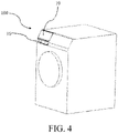
- FIG. 4 is a schematic three-dimensional diagram of a clothes treating device including a drawer panel according to an embodiment of the invention.
- FIG. 5 is a schematic three-dimensional diagram of the drawer panel in FIG. 4 from a perspective.
- FIG. 6 is a schematic three-dimensional diagram of the drawer panel in FIG. 4 from another perspective.
- embodiments of the invention relate to a clothes treating device 100 including a drawer panel 10, where the drawer panel 10 includes: a first portion 12, including a first front surface 14, a first rear surface 16, an assembling portion 18, and a decoration portion 20 at least partially enclosing the assembling portion 18; and a second portion 22, engaged with the first rear surface 16 and including a mounting portion 24.
- the first portion 12 of the drawer panel 10 of the clothes treating device 100 can be easily and inexpensively replaced.
- the clothes treating device 100 may be any device adapted to treat such as wash or dry clothes, for example, a washing machine, a washing and drying machine, or a clothes dryer, as long as the device is applicable to the invention.
- the drawer panel 10 may be a panel of a drawer-type detergent box, a water box, or another component of the clothes treating device 100.
- the first portion 12 may provide an appearance function for the drawer panel 10 by virtue of the decoration portion 20, and may be engaged with the second portion 22 and other components, for example, a decorating member 19 through the assembling portion 18.
- the decoration portion 20 may have any structure changing according to an industrial design.
- the second portion 22 may provide an assembly function for the drawer panel 10 by virtue of the mounting portion 24, so as to realize assembly between the drawer panel 10 and another component of the clothes treating device 100, for example, a drawer (not shown in the figure) located behind the drawer panel 10.
- the mounting portion 24 may be usually unchanged or substantially unchanged.
- front and rear may be used as orientations of the clothes treating device 100 relative to a user.
- the orientation close to the user is the "front”
- the orientation far away from the user is “rear”.
- the first portion 12 is a plastic part formed through injection molding, and is provided with a first demolding direction A1 (referring to FIG. 9 ), and the first portion 12 does not include two opposite faces interfering with the first demolding direction A1 in the first demolding direction A1.
- a mold slider may not be used when the first portion 12 is manufactured, which can help to simplify a mold and a manufacturing process of the drawer panel 10 of the clothes treating device 100.
- a plastic part formed through injection molding is provided with a demolding direction.
- a mold slider needs to be used, to ensure smooth demolding.
- the "interfering with” may include intersecting with the demolding direction. Therefore, when the first portion 12 is the plastic part formed through the injection molding, and does not include the two opposite faces interfering with the first demolding direction A1 in the first demolding direction A1 (a demolding direction of the first portion), the slider may be unnecessarily used in a mold of the first portion 12, to demold the first portion 12. In this way, the mold of the first portion 12 is simplified, thereby simplifying the mold and the manufacturing process of the drawer panel 10 of the clothes treating device 100.
- the second portion 22 is a plastic part formed through injection molding, and is provided with a second demolding direction A2 (referring to FIG. 11 and FIG. 12 ), and the second portion 22 does not include two opposite faces interfering with the second demolding direction A2 in the second demolding direction A2.
- a mold slider may not be used when the second portion 22 is manufactured, which can help to simplify the mold and the manufacturing process of the drawer panel 10 of the clothes treating device 100.
- the slider may be unnecessarily used in a mold of the second portion 22, to demold the second portion 22.
- the mold of the second portion 22 is simplified, thereby simplifying the mold and the manufacturing process of the drawer panel 10 of the clothes treating device 100.
- FIG. 7 is a schematic rear view of a first portion of the drawer panel in FIG. 4 .
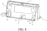
- FIG. 8 is a schematic three-dimensional diagram of a second portion of the drawer panel in FIG. 4 .
- the first portion 12 includes a first fitting portion 26 assembled with the second portion 22
- the mounting portion 24 includes a second fitting portion 28 assembled with the first fitting portion 26, and the first fitting portion 26 is located at the first rear surface 16.
- the second portion 22 can be engaged with the first rear surface 16 of the first portion 12.
- the first fitting portion 26 is located at the assembling portion 18.
- the first fitting portion 26 is located at the assembling portion 18, and the assembling portion 18 may be subsequently covered by, for example, the decorating member 19 to improve the aesthetics of the appearance of the drawer panel 10, to avoid affecting the appearance of the drawer panel 10 when being located at, for example, the decoration portion 20.
- the first fitting portion 26 includes a convex column 30, and the second fitting portion 28 includes a hole 32.
- the assembly between the first fitting portion 26 and the second fitting portion 28 can be realized by inserting the convex column 30 into the hole 32.
- the convex column 30 may be a column with any structure protruding from the first rear surface 16, as long as the column is applicable to the invention.
- the convex column 30 may be a substantially "cross"-shaped column with sharp ribs 31 on sides, or another type of column.
- the convex column 30 with the sharp ribs 31 is assembled with the hole 32, by means of interference fit, one side of the convex column 30 may abut against the hole 32, and a sharp rib 31 on an other side is damaged, thereby precisely positioning the first portion 12 and the second portion 22, and reducing tolerance accumulation.
- the hole 32 may be a hole with any structure adapted to fit in with the convex column 30, for example, may be a through hole, as long as the hole is applicable to the invention.
- FIG. 9 is a schematic cross-sectional view along a line A-A in FIG. 7 .
- the convex column 30 extends rearward from the first rear surface 16 in the first demolding direction A1.
- the first portion 12 can have a simple structure, and the mold slider may not be used, which can help to simplify the mold and the manufacturing process of the drawer panel 10 of the clothes treating device 100.
- the convex column 30 has an extension direction consistent with the first demolding direction A1, and is in a solid structure, and the first portion 12 does not include the two opposite faces interfering with the first demolding direction A1 in the first demolding direction A1. Therefore, the first portion 12 has a simple structure, and can be directly demolded in the first demolding direction A1 during manufacturing, so that there is no need to use the mold slider. Therefore, the mold and the manufacturing process of the drawer panel 10 of the clothes treating device 100 can be simplified.
- the second portion 22 includes a second front surface 34 and a second rear surface 36, and the second front surface 34 and the first rear surface 16 are engaged with each other.
- first portion 12 and the second portion 22 can be engaged together in a front-rear direction.
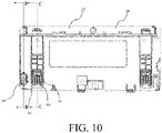
- FIG. 10 is a schematic rear view of a second portion.
- FIG. 11 is a schematic cross-sectional view along a line B-B in FIG. 10 .
- the mounting portion 24 includes a first engagement portion 38 extending rearward from the second rear surface 36 in the second demolding direction A2
- the second portion 22 includes a partition 40 that is located between and separates the first engagement portion 38 and the second front surface 34
- the partition 40 includes a solid portion 42 and/or a hollow portion 43 running through the solid portion 42 in the second demolding direction A2.
- the second portion 22 can have a simple structure, and the mold slider may not be used, which can help to simplify the mold and the manufacturing process of the drawer panel 10 of the clothes treating device 100.
- an extension direction of the first engagement portion 38 of the second portion 22 of the drawer panel 10 of the clothes treating device 100 of the present invention is consistent with the second demolding direction A2
- the partition 40 between the first engagement portion 38 and the second front surface 34 includes the solid portion 42 and/or the hollow portion 43 running through the solid portion 42 in the second demolding direction A2
- the second portion does not include the two opposite faces interfering with the second demolding direction A2 in the second demolding direction A2. Therefore, the second portion 22 has a simple structure, and can be directly demolded in the second demolding direction A2 during manufacturing, so that there is no need to use the mold slider. Therefore, the mold and the manufacturing process of the drawer panel 10 of the clothes treating device 100 can be simplified.
- the hollow portion 43 may be the hole 32 assembled with the convex column 30.
- FIG. 12 is a schematic cross-sectional view along a line C-C in FIG. 10 .
- the mounting portion 24 includes a second engagement portion 44 that is depressed rearward from the second front surface 34 and bent downward to extend, the second engagement portion 44 includes a droop portion 46, and the second portion 22 includes a cavity 48 opposite to the droop portion 46.
- the second portion 22 can have a simple structure, and the mold slider may not be used, which can help to simplify the mold and the manufacturing process of the drawer panel 10 of the clothes treating device 100.
- the second engagement portion 44 of the second portion 22 of the drawer panel 10 of the clothes treating device 100 of the present invention is depressed rearward from the second front surface 34 and bent downward to extend, the second portion 22 includes the cavity 48 opposite to the droop portion 46 of the second engagement portion 44, and does not include the two opposite faces interfering with the second demolding direction A2 in the second demolding direction A2. Therefore, the second portion 22 has a simple structure, and can be directly demolded in the second demolding direction A2 during manufacturing, so that there is no need to use the mold slider. Therefore, the mold and the manufacturing process of the drawer panel 10 of the clothes treating device 100 can be simplified.
- each of the first portion 12 and the second portion 22 of the drawer panel 10 of the clothes treating device 100 of the present invention does not include the two opposite faces interfering with the demolding direction in the demolding direction, and can be directly demolded during manufacturing, so that there is no need to use the mold sliders.
- the drawer panel 10 has a simple structure, and simplifies the mold and the manufacturing process.
- the first rear surface 16 completely covers the second front surface 34. In this way, the aesthetics of the appearance of the drawer panel 10 of the clothes treating device 100 can be improved.
- the first portion 12 includes a first reference portion 50
- the second portion 22 includes a second reference portion 52 corresponding to the first reference portion 50.
- first portion 12 and the second portion 22 can be positioned relative to each other and engaged.
- the first portion 12 and the second portion 22 can be positioned through the first reference portion 50 and the second reference portion 52, so that the first portion 12 and the second portion 22 are smoothly and easily engaged.
- the first reference portion 50 and the second reference portion 52 can have any possible structure, as long as the structure is applicable to the invention.
- the first reference portion 50 is located at the first rear surface 16 and the second reference portion 52 is located at the second front surface 34.
- first reference portion 50 and the second reference portion 52 can simply and conveniently correspond to each other.
- the first reference portion 50 and the second reference portion 52 can be aligned with each other as long as the first rear surface 16 and the second front surface 34 are opposite to each other.
- first reference portion 50 and the second reference portion 52 abut against each other.
- first portion 12 and the second portion 22 can be accurately positioned relative to each other.
- the first reference portion 50 includes a protruding portion 54
- the second reference portion 52 includes a concave hole portion 56 capable of accommodating the protruding portion 54.
- first reference portion 50 and the second reference portion 52 can be precisely positioned relative to each other.
- the protruding portion 54 is inserted into the concave hole portion 56, so that the first reference portion 50 and the second reference portion 52 precisely correspond to each other, and the first portion 12 and the second portion 22 are precisely positioned relative to each other.
- the protruding portion 54 may be, for example, a column protruding from the first rear surface 16, such as, a hollow cylinder, or a lug.
- the concave hole portion 56 may be, for example, a circular or square through hole capable of accommodating the protruding portion 54.
Landscapes
- Engineering & Computer Science (AREA)
- Manufacturing & Machinery (AREA)
- Mechanical Engineering (AREA)
- Textile Engineering (AREA)
- Drawers Of Furniture (AREA)
- Main Body Construction Of Washing Machines And Laundry Dryers (AREA)
Applications Claiming Priority (1)
| Application Number | Priority Date | Filing Date | Title |
|---|---|---|---|
| CN202121031343.6U CN216074417U (zh) | 2021-05-14 | 2021-05-14 | 包括抽屉面板的衣物处理装置 |
Publications (1)
| Publication Number | Publication Date |
|---|---|
| EP4091784A1 true EP4091784A1 (de) | 2022-11-23 |
Family
ID=80635593
Family Applications (1)
| Application Number | Title | Priority Date | Filing Date |
|---|---|---|---|
| EP22168868.2A Pending EP4091784A1 (de) | 2021-05-14 | 2022-04-19 | Kleiderbehandlungsvorrichtung mit einem schubladenpaneel |
Country Status (2)
| Country | Link |
|---|---|
| EP (1) | EP4091784A1 (de) |
| CN (1) | CN216074417U (de) |
Citations (4)
| Publication number | Priority date | Publication date | Assignee | Title |
|---|---|---|---|---|
| WO2017059907A1 (en) * | 2015-10-08 | 2017-04-13 | Arcelik Anonim Sirketi | Drawer assembly for a laundry machine |
| US20180363217A1 (en) * | 2017-06-14 | 2018-12-20 | Dongbu Daewoo Electronics Corporation | Wall-mounted washing machine, detergent container of wall-mounted washing machine, and front panel of wall-mounted washing machine |
| EP3511464A1 (de) * | 2018-01-15 | 2019-07-17 | Wuxi Little Swan Co., Ltd. | Waschmaschine und komponenten dafür |
| CN106884282B (zh) * | 2015-12-16 | 2020-10-30 | 青岛海尔滚筒洗衣机有限公司 | 一种洗涤剂盒以及滚筒洗衣机 |
-
2021
- 2021-05-14 CN CN202121031343.6U patent/CN216074417U/zh active Active
-
2022
- 2022-04-19 EP EP22168868.2A patent/EP4091784A1/de active Pending
Patent Citations (4)
| Publication number | Priority date | Publication date | Assignee | Title |
|---|---|---|---|---|
| WO2017059907A1 (en) * | 2015-10-08 | 2017-04-13 | Arcelik Anonim Sirketi | Drawer assembly for a laundry machine |
| CN106884282B (zh) * | 2015-12-16 | 2020-10-30 | 青岛海尔滚筒洗衣机有限公司 | 一种洗涤剂盒以及滚筒洗衣机 |
| US20180363217A1 (en) * | 2017-06-14 | 2018-12-20 | Dongbu Daewoo Electronics Corporation | Wall-mounted washing machine, detergent container of wall-mounted washing machine, and front panel of wall-mounted washing machine |
| EP3511464A1 (de) * | 2018-01-15 | 2019-07-17 | Wuxi Little Swan Co., Ltd. | Waschmaschine und komponenten dafür |
Also Published As
| Publication number | Publication date |
|---|---|
| CN216074417U (zh) | 2022-03-18 |
Similar Documents
| Publication | Publication Date | Title |
|---|---|---|
| EP2821541B1 (de) | Tür und Wäschebehandlungsgerät mit derselben | |
| USD527499S1 (en) | Washing machine | |
| US7073682B2 (en) | Snap assembly dishwasher basket | |
| EP4091784A1 (de) | Kleiderbehandlungsvorrichtung mit einem schubladenpaneel | |
| KR101084116B1 (ko) | 드럼세탁기의 도어 | |
| USD528711S1 (en) | Washing machine | |
| US20090211307A1 (en) | Washing machine | |
| KR20170133947A (ko) | 세탁기 | |
| CN101160429A (zh) | 清洁设备以及用于该清洁设备的制造和装配方法 | |
| KR101036463B1 (ko) | 건조덕트 구조 | |
| KR100793771B1 (ko) | 틸팅형 드럼세탁기의 톱플레이트 고정 구조 | |
| KR100465694B1 (ko) | 세탁기의 컨트롤 패널 구조 및 컨트롤 패널 성형용 사출금형 | |
| CN218523823U (zh) | 家用电器及其箱体的前盖 | |
| CN223386396U (zh) | 抽拉盒体的面板组件及家用电器 | |
| KR101207870B1 (ko) | 드럼 세탁기 | |
| CN210737156U (zh) | 包含抽屉式料盒的洗衣机 | |
| KR20140084945A (ko) | 세탁기용 캐비닛 | |
| KR101036468B1 (ko) | 드럼세탁기용 탑플레이트의 체결 구조 | |
| KR101560707B1 (ko) | 도어 및 이를 구비한 세탁기 | |
| KR20070070955A (ko) | 세탁 장치 | |
| KR20040011970A (ko) | 세탁기의 컨트롤패널 | |
| KR200336003Y1 (ko) | 액세서리 수납함 | |
| KR200402980Y1 (ko) | 세척 장치의 전면부 체결 구조 | |
| KR920008163Y1 (ko) | 플라스틱 범퍼의 마운팅 램프 장착구조 | |
| KR101033557B1 (ko) | 드럼세탁기의 캐비닛 커버 결합구조 |
Legal Events
| Date | Code | Title | Description |
|---|---|---|---|
| PUAI | Public reference made under article 153(3) epc to a published international application that has entered the european phase |
Free format text: ORIGINAL CODE: 0009012 |
|
| STAA | Information on the status of an ep patent application or granted ep patent |
Free format text: STATUS: THE APPLICATION HAS BEEN PUBLISHED |
|
| AK | Designated contracting states |
Kind code of ref document: A1 Designated state(s): AL AT BE BG CH CY CZ DE DK EE ES FI FR GB GR HR HU IE IS IT LI LT LU LV MC MK MT NL NO PL PT RO RS SE SI SK SM TR |
|
| STAA | Information on the status of an ep patent application or granted ep patent |
Free format text: STATUS: REQUEST FOR EXAMINATION WAS MADE |
|
| 17P | Request for examination filed |
Effective date: 20230523 |
|
| RBV | Designated contracting states (corrected) |
Designated state(s): AL AT BE BG CH CY CZ DE DK EE ES FI FR GB GR HR HU IE IS IT LI LT LU LV MC MK MT NL NO PL PT RO RS SE SI SK SM TR |