EP4091773A1 - Safety device, self-propelled robot system, and control method - Google Patents
Safety device, self-propelled robot system, and control method Download PDFInfo
- Publication number
- EP4091773A1 EP4091773A1 EP20914653.9A EP20914653A EP4091773A1 EP 4091773 A1 EP4091773 A1 EP 4091773A1 EP 20914653 A EP20914653 A EP 20914653A EP 4091773 A1 EP4091773 A1 EP 4091773A1
- Authority
- EP
- European Patent Office
- Prior art keywords
- area
- robot
- detection area
- travel
- given
- Prior art date
- Legal status (The legal status is an assumption and is not a legal conclusion. Google has not performed a legal analysis and makes no representation as to the accuracy of the status listed.)
- Pending
Links
Images




Classifications
-
- G—PHYSICS
- G05—CONTROLLING; REGULATING
- G05D—SYSTEMS FOR CONTROLLING OR REGULATING NON-ELECTRIC VARIABLES
- G05D1/00—Control of position, course, altitude or attitude of land, water, air or space vehicles, e.g. using automatic pilots
- G05D1/02—Control of position or course in two dimensions
- G05D1/021—Control of position or course in two dimensions specially adapted to land vehicles
- G05D1/0212—Control of position or course in two dimensions specially adapted to land vehicles with means for defining a desired trajectory
- G05D1/0214—Control of position or course in two dimensions specially adapted to land vehicles with means for defining a desired trajectory in accordance with safety or protection criteria, e.g. avoiding hazardous areas
-
- B—PERFORMING OPERATIONS; TRANSPORTING
- B25—HAND TOOLS; PORTABLE POWER-DRIVEN TOOLS; MANIPULATORS
- B25J—MANIPULATORS; CHAMBERS PROVIDED WITH MANIPULATION DEVICES
- B25J9/00—Program-controlled manipulators
- B25J9/16—Program controls
- B25J9/1615—Program controls characterised by special kind of manipulator, e.g. planar, scara, gantry, cantilever, space, closed chain, passive/active joints and tendon driven manipulators
- B25J9/162—Mobile manipulator, movable base with manipulator arm mounted on it
-
- B—PERFORMING OPERATIONS; TRANSPORTING
- B25—HAND TOOLS; PORTABLE POWER-DRIVEN TOOLS; MANIPULATORS
- B25J—MANIPULATORS; CHAMBERS PROVIDED WITH MANIPULATION DEVICES
- B25J13/00—Controls for manipulators
- B25J13/08—Controls for manipulators by means of sensing devices, e.g. viewing or touching devices
- B25J13/086—Proximity sensors
-
- B—PERFORMING OPERATIONS; TRANSPORTING
- B25—HAND TOOLS; PORTABLE POWER-DRIVEN TOOLS; MANIPULATORS
- B25J—MANIPULATORS; CHAMBERS PROVIDED WITH MANIPULATION DEVICES
- B25J13/00—Controls for manipulators
- B25J13/08—Controls for manipulators by means of sensing devices, e.g. viewing or touching devices
- B25J13/088—Controls for manipulators by means of sensing devices, e.g. viewing or touching devices with position, velocity or acceleration sensors
- B25J13/089—Determining the position of the robot with reference to its environment
-
- B—PERFORMING OPERATIONS; TRANSPORTING
- B25—HAND TOOLS; PORTABLE POWER-DRIVEN TOOLS; MANIPULATORS
- B25J—MANIPULATORS; CHAMBERS PROVIDED WITH MANIPULATION DEVICES
- B25J19/00—Accessories fitted to manipulators, e.g. for monitoring, for viewing; Safety devices combined with or specially adapted for use in connection with manipulators
- B25J19/02—Sensing devices
- B25J19/021—Optical sensing devices
- B25J19/022—Optical sensing devices using lasers
-
- B—PERFORMING OPERATIONS; TRANSPORTING
- B25—HAND TOOLS; PORTABLE POWER-DRIVEN TOOLS; MANIPULATORS
- B25J—MANIPULATORS; CHAMBERS PROVIDED WITH MANIPULATION DEVICES
- B25J19/00—Accessories fitted to manipulators, e.g. for monitoring, for viewing; Safety devices combined with or specially adapted for use in connection with manipulators
- B25J19/06—Safety devices
-
- B—PERFORMING OPERATIONS; TRANSPORTING
- B25—HAND TOOLS; PORTABLE POWER-DRIVEN TOOLS; MANIPULATORS
- B25J—MANIPULATORS; CHAMBERS PROVIDED WITH MANIPULATION DEVICES
- B25J5/00—Manipulators mounted on wheels or on carriages
- B25J5/007—Manipulators mounted on wheels or on carriages mounted on wheels
-
- B—PERFORMING OPERATIONS; TRANSPORTING
- B25—HAND TOOLS; PORTABLE POWER-DRIVEN TOOLS; MANIPULATORS
- B25J—MANIPULATORS; CHAMBERS PROVIDED WITH MANIPULATION DEVICES
- B25J9/00—Program-controlled manipulators
- B25J9/06—Program-controlled manipulators characterised by multi-articulated arms
-
- B—PERFORMING OPERATIONS; TRANSPORTING
- B25—HAND TOOLS; PORTABLE POWER-DRIVEN TOOLS; MANIPULATORS
- B25J—MANIPULATORS; CHAMBERS PROVIDED WITH MANIPULATION DEVICES
- B25J9/00—Program-controlled manipulators
- B25J9/16—Program controls
- B25J9/1656—Program controls characterised by programming, planning systems for manipulators
- B25J9/1664—Program controls characterised by programming, planning systems for manipulators characterised by motion, path, trajectory planning
-
- B—PERFORMING OPERATIONS; TRANSPORTING
- B25—HAND TOOLS; PORTABLE POWER-DRIVEN TOOLS; MANIPULATORS
- B25J—MANIPULATORS; CHAMBERS PROVIDED WITH MANIPULATION DEVICES
- B25J9/00—Program-controlled manipulators
- B25J9/16—Program controls
- B25J9/1674—Program controls characterised by safety, monitoring, diagnostic
- B25J9/1676—Avoiding collision or forbidden zones
-
- G—PHYSICS
- G05—CONTROLLING; REGULATING
- G05B—CONTROL OR REGULATING SYSTEMS IN GENERAL; FUNCTIONAL ELEMENTS OF SUCH SYSTEMS; MONITORING OR TESTING ARRANGEMENTS FOR SUCH SYSTEMS OR ELEMENTS
- G05B19/00—Program-control systems
- G05B19/02—Program-control systems electric
- G05B19/418—Total factory control, i.e. centrally controlling a plurality of machines, e.g. direct or distributed numerical control [DNC], flexible manufacturing systems [FMS], integrated manufacturing systems [IMS] or computer integrated manufacturing [CIM]
- G05B19/4189—Total factory control, i.e. centrally controlling a plurality of machines, e.g. direct or distributed numerical control [DNC], flexible manufacturing systems [FMS], integrated manufacturing systems [IMS] or computer integrated manufacturing [CIM] characterised by the transport system
- G05B19/41895—Total factory control, i.e. centrally controlling a plurality of machines, e.g. direct or distributed numerical control [DNC], flexible manufacturing systems [FMS], integrated manufacturing systems [IMS] or computer integrated manufacturing [CIM] characterised by the transport system using automatic guided vehicles [AGV]
-
- G—PHYSICS
- G05—CONTROLLING; REGULATING
- G05D—SYSTEMS FOR CONTROLLING OR REGULATING NON-ELECTRIC VARIABLES
- G05D1/00—Control of position, course, altitude or attitude of land, water, air or space vehicles, e.g. using automatic pilots
- G05D1/02—Control of position or course in two dimensions
- G05D1/021—Control of position or course in two dimensions specially adapted to land vehicles
- G05D1/0231—Control of position or course in two dimensions specially adapted to land vehicles using optical position detecting means
- G05D1/0246—Control of position or course in two dimensions specially adapted to land vehicles using optical position detecting means using a video camera in combination with image processing means
- G05D1/0248—Control of position or course in two dimensions specially adapted to land vehicles using optical position detecting means using a video camera in combination with image processing means in combination with a laser
-
- G—PHYSICS
- G05—CONTROLLING; REGULATING
- G05D—SYSTEMS FOR CONTROLLING OR REGULATING NON-ELECTRIC VARIABLES
- G05D1/00—Control of position, course, altitude or attitude of land, water, air or space vehicles, e.g. using automatic pilots
- G05D1/20—Control system inputs
- G05D1/24—Arrangements for determining position or orientation
- G05D1/247—Arrangements for determining position or orientation using signals provided by artificial sources external to the vehicle, e.g. navigation beacons
-
- G—PHYSICS
- G05—CONTROLLING; REGULATING
- G05D—SYSTEMS FOR CONTROLLING OR REGULATING NON-ELECTRIC VARIABLES
- G05D1/00—Control of position, course, altitude or attitude of land, water, air or space vehicles, e.g. using automatic pilots
- G05D1/60—Intended control result
- G05D1/617—Safety or protection, e.g. defining protection zones around obstacles or avoiding hazards
-
- G—PHYSICS
- G05—CONTROLLING; REGULATING
- G05B—CONTROL OR REGULATING SYSTEMS IN GENERAL; FUNCTIONAL ELEMENTS OF SUCH SYSTEMS; MONITORING OR TESTING ARRANGEMENTS FOR SUCH SYSTEMS OR ELEMENTS
- G05B2219/00—Program-control systems
- G05B2219/30—Nc systems
- G05B2219/40—Robotics, robotics mapping to robotics vision
- G05B2219/40203—Detect position of operator, create non material barrier to protect operator
-
- G—PHYSICS
- G05—CONTROLLING; REGULATING
- G05B—CONTROL OR REGULATING SYSTEMS IN GENERAL; FUNCTIONAL ELEMENTS OF SUCH SYSTEMS; MONITORING OR TESTING ARRANGEMENTS FOR SUCH SYSTEMS OR ELEMENTS
- G05B2219/00—Program-control systems
- G05B2219/30—Nc systems
- G05B2219/40—Robotics, robotics mapping to robotics vision
- G05B2219/40298—Manipulator on vehicle, wheels, mobile
-
- G—PHYSICS
- G05—CONTROLLING; REGULATING
- G05B—CONTROL OR REGULATING SYSTEMS IN GENERAL; FUNCTIONAL ELEMENTS OF SUCH SYSTEMS; MONITORING OR TESTING ARRANGEMENTS FOR SUCH SYSTEMS OR ELEMENTS
- G05B2219/00—Program-control systems
- G05B2219/30—Nc systems
- G05B2219/49—Nc machine tool, till multiple
- G05B2219/49138—Adapt working envelop, limit, allowed zone to speed of tool
-
- G—PHYSICS
- G05—CONTROLLING; REGULATING
- G05B—CONTROL OR REGULATING SYSTEMS IN GENERAL; FUNCTIONAL ELEMENTS OF SUCH SYSTEMS; MONITORING OR TESTING ARRANGEMENTS FOR SUCH SYSTEMS OR ELEMENTS
- G05B2219/00—Program-control systems
- G05B2219/30—Nc systems
- G05B2219/50—Machine tool, machine tool null till machine tool work handling
- G05B2219/50393—Floor conveyor, AGV automatic guided vehicle
Definitions
- the present disclosure relates to a safety device, a self-propelled robot system, and a controlling method.
- the reflection factor of a robot with a higher priority is set higher than the reflection factor of a robot with a lower priority.
- a sensing signal emitted from the robot with the lower priority is reflected by the robot with the higher priority, and the light is received with sufficient intensity by the robot with the lower priority.
- the sensing signal emitted from the robot with the higher priority is reflected by the robot with the lower priority, and the light is received with insufficient intensity by the robot with the higher priority.
- the safety device of Patent Document 1 allows the robot with the higher priority to work with a higher priority.
- one purpose of the present disclosure is to provide a safety device, a self-propelled robot system, and a controlling method, capable of suppressing motions of a travel device and a robot according to operating states of the travel device and the robot.
- a safety device includes a sensor that is attached to a self-propellable travel device or a robot provided to the travel device, is set with a given detection area on the basis of a position of the sensor, and detects an object existing within the given detection area, a motion suppressing device that suppresses motions of the travel device and the robot, when the existence of the object within the given detection area is detected by the sensor, and an area changing device that changes the given detection area according to operating states of the travel device and the robot.
- a safety device capable of suppressing motions of a travel device and a robot according to operating states of the travel device and the robot.
- FIG. 1 is a schematic view illustrating a situation that a self-propelled robot system according to this embodiment is applied to a work site.
- the self-propelled robot system 10 according to this embodiment is used for conveying a plurality of workpieces W which are sequentially conveyed by a conveyor C to one of a plurality of shelves S arrayed in parallel to a conveying direction of the conveyor C.
- two self-propelled robot systems 10 are disposed between the conveyor C and the plurality of shelves S. Note that a worker P is located near the two self-propelled robot systems 10, to perform the conveying work which is the same as that of the two self-propelled robot systems 10.
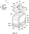
- FIG. 2 is a perspective view illustrating the entire configuration of the self-propelled robot system according to this embodiment.
- the self-propelled robot system 10 includes an AGV (Automated Guided Vehicle) 20 as a self-propellable travel device, and a vertical articulated robot 40 as a robot provided on an upper surface of the AGV 20. Further, the self-propelled robot system 10 further includes a safety device 50 which is provided for the AGV 20 and the vertical articulated robot 40.
- AGV Automate Guided Vehicle
- the AGV 20 includes a rectangular parallelepiped casing 22, a drive 24 (see FIG. 4 ) provided inside the casing 22, two driving wheels 26a and 26b which are driven by the drive 24, and four wheels 27a-27d which are not connected to the drive 24.
- the driving wheel 26a is provided to the center of a left edge part of the bottom surface of the AGV 20, and it is driven by a servomotor 110g (see FIG. 4 ) of the drive 24 (same as above).
- the driving wheel 26b is provided to the center of a right edge part of the bottom surface of the AGV 20, and it is driven by a servomotor 110h (same as above) of the drive 24 (same as above).
- the AGV 20 can spin, and can make a right turn and a left turn by differentiating rotational speeds of the driving wheels 26a and 26b from each other.
- the four wheels 27a-27d are provided to corner parts of the bottom surface of the AGV 20, respectively. Each of the four wheels 27a-27d may be an omnidirectional caster wheel.
- the vertical articulated robot 40 includes a pedestal 41 which is fixed to the upper surface of the casing 22 of the AGV 20, a robotic arm 42 of which a base end is coupled to the pedestal 41, an end effector (not illustrated) provided to a tip end of the robotic arm 42, and a robot control device 100 (see FIG. 4 : control device) for controlling operations of the robotic arm 42 and the end effector.
- the robotic arm 42 includes six joint axes JT1-JT6, and five links 24a-24e serially coupled through the joint axes JT1-JT6. Note that the joint axes JT1-JT6 are driven by servomotors 110a-110f, respectively (see FIG. 4 ).
- the joint axis JT1 couples the pedestal 41 to a base end of the link 44a so as to be rotatable on an axis extending in the vertical direction.
- the rotation of the link 44a with respect to the pedestal 41 is performed by the servomotor 110a (see FIG. 4 ).
- the joint axis JT2 couples a tip end of the link 44a to a base end of the link 44b so as to be rotatable on an axis extending in the horizontal direction.
- the rotation of the link 44b with respect to the link 44a is performed by the servomotor 110b (same as above).
- the joint axis JT3 couples a tip end of the link 44b to a base end of the link 44c so as to be rotatable on an axis extending in the horizontal direction.
- the rotation of the link 44c with respect to the link 44b is performed by the servomotor 110c (same as above).
- the joint axis JT4 couples a tip end of the link 44c to a base end of the link 44d so as to be rotatable on an axis extending in the longitudinal direction of the link 44c.
- the rotation of the link 44d with respect to the link 44c is performed by the servomotor 110d (see FIG. 4 ).
- the joint axis JT5 couples a tip end of the link 44d to a base end of the link 44e so as to be rotatable on an axis extending in a direction perpendicular to the longitudinal direction of the link 44d.
- the rotation of the link 44e with respect to the link 44d is performed by the servomotor 110e (same as above).
- the joint axis JT6 couples a tip end of the link 44e to a base end of the end effector (not illustrated) so as to be twistable.
- the rotation of the end effector with respect to the link 44e is performed by the servomotor 110f (same as above).
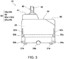
- FIG. 3 is a side view illustrating a configuration of a substantial part of the self-propelled robot system according to this embodiment.
- FIG. 4 is a block diagram illustrating a control system of the self-propelled robot system.
- the safety device 50 according to this embodiment is provided with two laser sensors 52a and 52b (sensors) attached to the casing 22 of the AGV 20.
- the laser sensor 52a is attached to a bottom part at a corner where the front surface and the right surface of the casing 22 meet
- the laser sensor 52b is attached to a bottom part at a corner where the rear surface and the left surface of the casing 22 meet.
- the laser sensors 52a and 52b are provided to respective two corners of the casing 22 which are not adjacent to each other in the plan view.
- the laser sensor 52b has the same structure as the laser sensor 52a. Therefore, below, unless particularly required, only the laser sensor 52a is described, and similar explanation will not be repeated for the laser sensor 52b.
- the laser sensor 52a includes a light source 53 which radially emits a laser beam centering on itself, within a given detectable area Da (see FIG. 5 ) which will be described later, a photo detector 54 which is disposed adjacent to the light source 53, and receives the laser beam which is bounced back from an object which exists within the given detectable area Da (e.g., the other self-propelled robot system 10 and the worker P which are illustrated in FIG. 1 ), and a detector 55 which detects the object which exists within the given detectable area Da (same as above) based on a light-receiving state of the photo detector 54.
- a buzzer 60, state indicating lamps 62a-62d, and bumper switches 64a and 64b, which are illustrated in FIG. 3 will be described later.
- the robot control device 100 is provided with a motion control device 102 for controlling operations of the AGV 20 and the vertical articulated robot 40.
- the motion control device 102 is capable of servo-controlling operation of the robotic arm 42.
- the motion control device 102 is also capable of servo-controlling operation of the end effector (not illustrated) provided to a tip end of the robotic arm 42, as an external axis.
- the motion control device 102 is also capable of servo-controlling operation of the driving wheels 26a and 26b as external axes, and is also capable of servo-controlling operation of the driving wheels 26c and 26d as external axes.
- the robot control device 100 may control operation of the buzzer 60, the state indicating lamps 62a-62d, and the bumper switches 64a and 64b, which will be described later.
- a motion suppressing device 104 and an area changing device 106 which are illustrated in FIG. 4 will be described later.
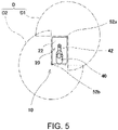
- FIG. 5 is a schematic view illustrating a given detectable area which is set by the safety device according to this embodiment.
- the laser sensor 52a radially emits the laser beam by the light source 53, centering on itself.
- the laser sensor 52a since the laser sensor 52a is attached to the bottom part at the corner of the casing 22 of the AGV 20 where the front surface and the right surface meet, there is an area to which the laser beam cannot be emitted because the laser beam is obstructed by the casing 22. That is, the laser sensor 52a can radially emit the laser beam centering on itself in the plan view to a 270° area from the front surface to the right surface of the casing 22. Therefore, the laser sensor 52a becomes possible to detect the object which exists within the detectable area Da illustrated by two-dot chain lines in FIG. 5 .
- the laser sensor 52b radially emits a laser beam centering on itself by the light source 53.
- the laser sensor 52b since the laser sensor 52b is attached to the bottom part at the corner of the casing 22 of the AGV 20 where the rear surface and the left surface meet, there in an area to which the laser beam cannot be emitted exists because the laser beam is obstructed by the casing 22. That is, the laser sensor 52b can radially emit the laser beam centering on itself in the plan view to a 270° area from the rear surface to the left surface of the casing 22. Therefore, the laser sensor 52b becomes possible to detect the object which exists within a detectable area Db illustrated by the two-dot chain line in FIG. 5 .
- the detectable area D by the safety device 50 is an area which combines the detectable area Da by the laser sensor 52a and the detectable area Db by the laser sensor 52b. Note that, as illustrated in FIG. 5 , the detectable area Da and the detectable area Db partially overlap with each other in the plan view.
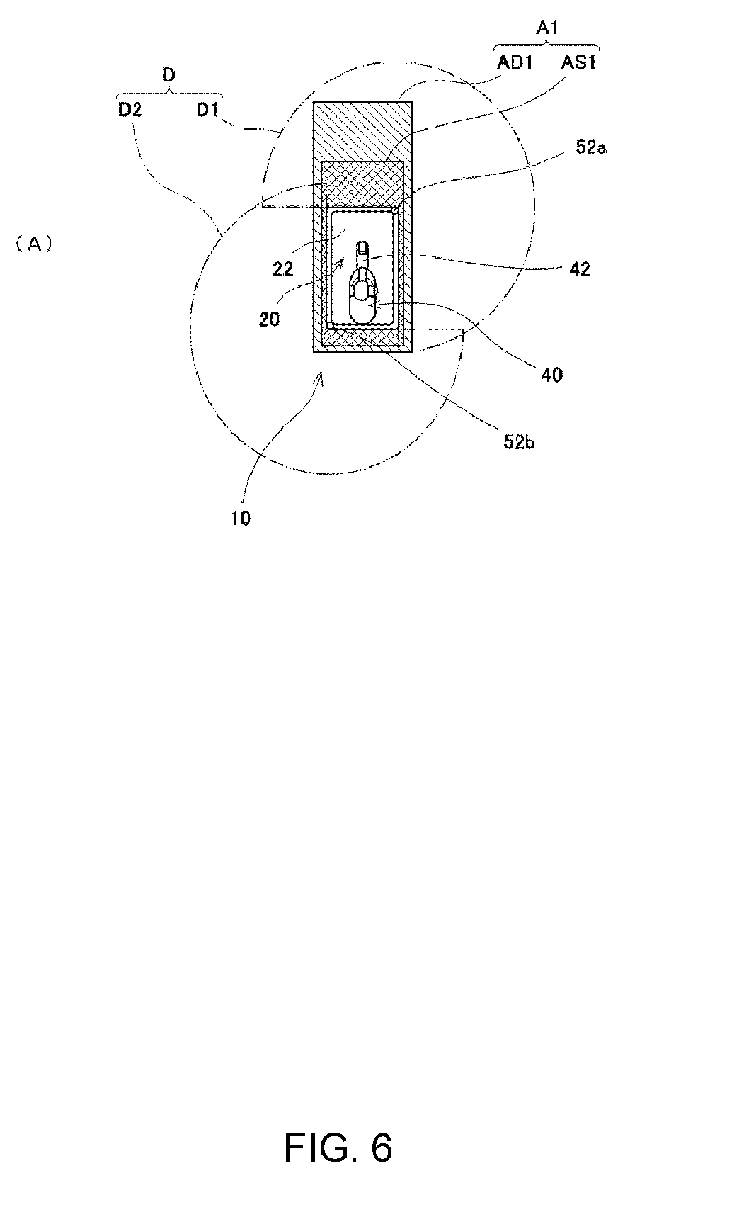
- FIGs. 6(A) and 6(B) are schematic views illustrating a given detection area which is set by the safety device according to this embodiment, where FIG. 6(A) is a schematic view illustrating a first detection area, and FIG. 6(B) is a schematic view illustrating a second detection area.
- FIG. 6(A) a state where the vertical articulated robot 40 is not operating, but the AGV 20 is traveling forward is illustrated.
- the laser sensors 52a and 52b are provided so that a detection area A1 (given detection area, first detection area) is set on the basis of the positions of the laser sensors 52a and 52b, and the laser sensors 52a and 52b detect an object which exists within this detection area A1.
- the detection area A1 is a part of the detectable area D. In other words, the detection area A1 is included in the detectable area D.
- the area changing device 106 sets the detection area A1 by masking a part of the detectable area D.
- the detection area A1 is set so that it extends from the AGV 20 at least in the traveling direction of the AGV 20.
- the detection area A1 is set so that it becomes in a rectangular shape in the plan view, which extends forward of the AGV 20 from the AGV 20, and also extends slightly rearward of the AGV 20 from the AGV 20.
- the detection area A1 is set so that it has a rectangular shape including the AGV 20 in the plan view, and it also exists slightly on both the left and right sides of the AGV 20.
- the area changing device 106 can set a slowdown area AD 1 and a stop area AS1 within the detection area A1 (given detection area, first detection area). As illustrated, the slowdown area AD 1 and the stop area AS1 are set so that each has a rectangular shape, and the stop area AS1 includes the slowdown area AD 1.
- the motion suppressing device 104 When the existence of the object is detected within the slowdown area AD1 by the laser sensors 52a and 52b, the motion suppressing device 104 (see FIG. 4 ) suppresses the motion of the AGV 20 by slowing down the traveling of the AGV 20. Further, when the existence of the object is detected within the stop area AS1 by the laser sensors 52a and 52b, the motion suppressing device 104 suppresses the motion of the AGV 20 by stopping the traveling of the AGV 20. Note that, when the existence of the object is detected both in the slowdown area AD1 and the stop area AS1, the motion suppressing device 104 may suppress the motion of the AGV 20 by stopping the traveling of the AGV 20.
- the safety device 50 is further provided with a buzzer 60 which is attached to a corner of the casing 22 of the AGV 20 where the front surface and the upper surface meet.
- the buzzer 60 is attached so that it extends in the width direction of the casing 22.
- the buzzer 60 may emit a warning sound to inform that a danger situation occurs. Further, when the existence of the object is detected within the stop area AS1 by the laser sensors 52a and 52b, the buzzer 60 may emit a louder warning sound than when the existence of the object is detected within the slowdown area AD1, to inform that the danger situation occurs.
- the safety device 50 further includes the state indicating lamps 62a-62d which are attached to a center part of a corner of the casing 22 of the AGV 20 where the front surface and the left surface meet, a center part of the corner of the casing 22 where the front surface and the right surface meet, a center part of the corner of the casing 22 where the rear surface and the left surface meet, and a center part of a corner of the casing 22 where the rear surface and the right surface meet, respectively.
- the state indicating lamps 62a-62b may inform that a danger situation occurs by turning on the lamp (or by blinking it), when the existence of the object is detected within the slowdown area AD1 by the laser sensors 52a and 52b.
- the state indicating lamps 62a-62b may inform that a danger situation occurs by tuning on the lamp in a color different from that is used when the existence of the object is detected within the slowdown area AD1 (or by blinking it violently).
- the safety device 50 further includes the bumper switch 64a which is attached to the corner of the casing 22 of the AGV 20 where the front surface and the bottom surface meet, and extends in the width direction of the casing 22, and the bumper switch 64b which is attached to the corner of the casing 22 of the AGV 20 where the rear surface and the bottom surface meet, and extends in the width direction of the casing 22.
- the bumper switches 64a and 64b stop the operations of the AGV 20 and the vertical articulated robot 40, when the object collides the bumper switches 64a and 64b, respectively.
- FIG. 6(B) a state where the AGV 20 is not traveling, but the vertical articulated robot 40 is operating is illustrated.
- the laser sensors 52a and 52b are provided so that a detection area A2 (given detection area, second detection area) is set on the basis of the positions of the laser sensors 52a and 52b, and the laser sensors 52a and 52b detect the object which exists within the detection area A2.
- the detection area A2 is a part of the detectable area D. In other words, the detection area A2 is included in the detectable area D.
- the area changing device 106 sets the detection area A2 by masking a part of the detectable area D which is different from the detection area A1.
- the detection area A2 is set so that it extends from the vertical articulated robot 40 at least toward a movable area where the vertical articulated robot 40 is operable.
- the detection area A2 extends rightward from the AGV 20 so as to include the robotic arm 42.
- a part of the detection area A2 other than the part including the robotic arm 42 is set so as to have a rectangular shape which includes the casing 22 of the AGV 20 in the plan view.
- the area changing device 106 can set a slowdown area AD2 and a stop area AS2 within the detection area A2 (given detection area, second detection area). As illustrated, the stop area AS2 is set so as to include the slowdown area AD2.
- the motion suppressing device 104 When the existence of the object within the slowdown area AD2 is detected by the laser sensors 52a and 52b, the motion suppressing device 104 (see FIG. 4 ) decelerates the motion of the vertical articulated robot 40 to suppress the motion of the vertical articulated robot 40. Further, when the existence of the object within the stop area AS2 is detected by the laser sensors 52a and 52b, the motion suppressing device 104 stops the vertical articulated robot 40 to suppress the motion of the vertical articulated robot 40. Note that, when the existence of the object is detected both in the slowdown area AD2 and the stop area AS2, the motion suppressing device 104 may stop the vertical articulated robot 40 to suppress the motion of the vertical articulated robot 40.
- the area changing device 106 can switch between the detection area A1 illustrated in FIG. 6(A) and the detection area A2 illustrated in FIG. 6(B) by changing the masked part of the detectable area D according to the operating states of the AGV 20 and the vertical articulated robot 40.
- the safety device 50 can switch between the detection area A1 and the detection area A2 by the area changing device 106 according to the operating states of the AGV 20 and the vertical articulated robot 40. Therefore, the safety device 50 becomes possible to suppress the motions of the AGV 20 and the vertical articulated robot 40 according to the operating states of the AGV 20 and the vertical articulated robot 40.
- the area changing device 106 sets the detection area A1 illustrated in FIG. 6(A) by masking a part of the detectable area D. Further, when the AGV 20 is not traveling, but the vertical articulated robot 40 is operating, the area changing device 106 sets the detection area A2 illustrated in FIG. 6(B) by masking a different part of the detectable area D from the detection area A1.
- the area changing device 106 sets the detection area A2 illustrated in FIG. 6(B) by masking a different part of the detectable area D from the detection area A1.
- the area changing device 106 sets the slowdown area AD1 and the stop area AS1 within the detection area A1, and sets the slowdown area AD2 and the stop area AS2 within the detection area A2.
- the area changing device 106 sets the slowdown area AD1 and the stop area AS1 within the detection area A1, and sets the slowdown area AD2 and the stop area AS2 within the detection area A2.
- the casing 22 of the AGV 20 is formed in the rectangular parallelepiped shape, and the laser sensors 52a and 52b are provided to the respective two corners of the casing 22, which are not adjacent to each other in the plan view.
- the laser sensors 52a and 52b are provided to the respective two corners of the casing 22, which are not adjacent to each other in the plan view.
- the safety device 50 Since the safety device 50 according to this embodiment is provided with the buzzer 60, the state indicating lamps 62a-62d, and the bumper switches 64a and 64b, it becomes possible to secure the safety much more certainly.
- FIG. 7 is a schematic view illustrating a third detection area which is set by the safety device according to this embodiment.
- the area changing device 106 sets a detection area A3 (given detection area, third detection area) by masking a part of the detectable area D which is different from the detection areas A1 and A2.
- the detection area A3 is set to become a circle so that its center overlaps with the center of the casing 22 of the AGV 20 in the plan view.
- the area changing device 106 can set a slowdown area AD3 and a stop area AS3 within the detection area A3.
- the slowdown area AD3 and the stop area AS3 are concentric circles, and the stop area AS3 includes the slowdown area AD3.
- the area changing device 106 may change the size of the detection area A3 (in other words, the sizes of the slowdown area AD3 and the stop area AS3) according to operating speeds of the AGV 20 and the vertical articulated robot 40. For example, when at least one of the AGV 20 and the vertical articulated robot 40 carries out a high-speed operation, the area changing device 106 may increase the detection area A3.
- the area changing device 106 may make the shape of the detection area as the shape of the detection area A1 illustrated in FIG. 6(A) or may make it as the shape of the detection area A2 illustrated in FIG. 6(B) , instead of the shape of the detection area A3 illustrated in FIG. 7 .
- the casing 22 has the rectangular parallelepiped shape, and the laser sensors 52a and 52b are provided to the two corners of the casing 22 which are not adjacent to each other in the plan view.
- the casing 22 may have a polygonal prism shape other than the rectangular parallelepiped shape, or may have other shapes.
- only one laser sensor may be disposed at the center of the upper surface of the casing 22.
- one or, three or more laser sensors may be attached to the casing 22.
- the laser sensor may be attached to the vertical articulated robot 40.
- the area changing device 106 is switchable between the detection area A1 (first detection area) illustrated in FIG. 6(A) and the detection area A2 (second detection area) illustrated in FIG. 6(B) .
- the first detection area may be set to have, in the plan view, an oval shape which extends from the AGV 20 at least in the traveling direction of the AGV 20, or may be set to have other shapes.
- the second detection area may be set to have, in the plan view, a rectangular shape which is different from the shape of the first detection area, or may be set to have other shapes.
- the area changing device 106 sets the slowdown area AD1 and the stop area AS1 within the detection area A1 (given detection area, first detection area), and sets the slowdown area AD2 and the stop area AS2 within the detection area A2 (given detection area, second detection area).
- the area changing device 106 may be settable of at least either one of the slowdown area and the stop area within the given detection area.
- the senor is comprised of so-called “reflection type” laser sensors 52a and 52b.
- the sensor may be comprised of a so-called “transmission type” laser sensor which collaborates with a sensor attached to an outer wall etc., or may be comprised of other sensors.
- the robot is comprised of the vertical articulated robot 40 which has the six joint axes JT1-JT6.
- the robot may be comprised of a vertical articulated robot which has at least one joint axis, not with the six axes.
- the robot may be comprised of a dual-arm robot, or may be comprised of a horizontal articulated robot, or may be comprised of other robots.
- the motion suppressing device 104 and the area changing device 106 are constituted as a part of the robot control device 100 (control device) for controlling the operations of the AGV 20 and the vertical articulated robot 40, respectively.
- the motion suppressing device and the area changing device may be provided separately from the control device.
- FIG. 8 is a flowchart illustrating the controlling method according to this embodiment.
- the laser sensors 52a and 52b perform a first step for setting a given detection area (in FIG. 8 , Step S1).
- the area changing device 106 performs a second step for changing the given detection area (in FIG. 8 , Step S2).
- the motion suppressing device 104 performs a third step for suppressing the motions of the AGV 20 (travel device) and the vertical articulated robot 40 (robot) (in FIG. 8 , Step S3).
- the controlling method according to this embodiment becomes possible to suppress the AGV 20 and the vertical articulated robot 40 according to the operating states of the AGV 20 (travel device) and the vertical articulated robot 40 (robot), by using the safety device 50 described above.
- the safety device includes the sensor that is attached to the self-propellable travel device or the robot provided to the travel device, is set with the given detection area on the basis of the position of the sensor, and detects the object existing within the given detection area, the motion suppressing device that suppresses motions of the travel device and the robot, when the existence of the object within the given detection area is detected by the sensor, and the area changing device that changes the given detection area according to the operating states of the travel device and the robot.
- the safety device is capable of suppressing the motions of the travel device and the robot according to the operating states of the travel device and the robot.
- the area changing device may be changeable between the first detection area as the given detection area extending from the travel device at least in the traveling direction of the travel device, when the robot does not operate and the travel device travels, and the second detection area as the given detection area extending from the robot at least toward the movable area where the robot is operable, when the travel device does not travel and the robot operates.
- the safety device is capable of efficiently suppressing the motions of the travel device and the robot.
- the area changing device may be changeable of the given detection area to the third detection area, when the travel device travels and the robot operates.
- the area changing device may be settable of at least either one of the slowdown area and the stop area within the given detection area.
- the motion suppressing device may decelerate the motions of the travel device and the robot, and when the existence of the object is detected within the stop area by the sensor, the motion suppressing device may stop the motions of the travel device and the robot.
- the safety device can appropriately suppress the motions of the travel device and the robot.
- the senor may be constituted as the laser sensor having the light source that radially emits a laser beam centering on the light source, within the given detectable area including the given detection area, the photo detector that is disposed adjacent to the light source, and receives the laser beam bounced back from the object existing within the given detectable area, and the detector that detects the object existing within the given detectable area based on the light-receiving state of the photo detector.
- the area changing device may change the given detection area by changing the masked part of the given detectable area.
- the travel device may have the rectangular parallelepiped casing, the drive provided to the casing, and the driving wheel driven by the drive.
- the laser sensor may be provided to at least two corners of the casing that are not adjacent to each other in a plan view.
- the safety device is capable of obtaining the sufficiently large detectable area without being provided with laser sensors beyond necessity.
- At least one of the area changing device and the motion suppressing device may be constituted as a part of the control device that controls the operations of the travel device and the robot.
- the entire device can be more compact.
- the self-propelled robot system includes the safety device having any one of the configurations described above, the travel device, and the robot.
- the self-propelled robot system since the self-propelled robot system according to one embodiment of the present disclosure is provided with the safety device having any one of the configurations described above, it becomes possible to suppress the motions of the travel device and the robot according to the operating states of the travel device and the robot.
- the robot may be constituted as the vertical articulated robot.
- the travel device may be constituted as the automated guided vehicle.
- the controlling method is the method of controlling operations of the travel device and the robot by using the safety device having any one of the configurations described above, which includes the steps of (first step) setting the given detection area, (second step) changing the given detection area by the area changing device according to the operating states of the travel device and the robot, and (third step) suppressing the motions of the travel device and the robot by the motion suppressing device, when the existence of the object within the given detection area is detected by the sensor.
- the controlling method uses the safety device having any one of the configurations described above so as to suppress the motions of the travel device and the robot according to the operating states of the travel device and the robot.
Landscapes
- Engineering & Computer Science (AREA)
- Robotics (AREA)
- Mechanical Engineering (AREA)
- Physics & Mathematics (AREA)
- General Physics & Mathematics (AREA)
- Automation & Control Theory (AREA)
- Remote Sensing (AREA)
- Radar, Positioning & Navigation (AREA)
- Aviation & Aerospace Engineering (AREA)
- Optics & Photonics (AREA)
- Human Computer Interaction (AREA)
- General Health & Medical Sciences (AREA)
- Orthopedic Medicine & Surgery (AREA)
- Health & Medical Sciences (AREA)
- Computer Vision & Pattern Recognition (AREA)
- Multimedia (AREA)
- Electromagnetism (AREA)
- Quality & Reliability (AREA)
- Manufacturing & Machinery (AREA)
- General Engineering & Computer Science (AREA)
- Manipulator (AREA)
- Control Of Position, Course, Altitude, Or Attitude Of Moving Bodies (AREA)
Abstract
Description
- The present disclosure relates to a safety device, a self-propelled robot system, and a controlling method.
- Conventionally, it is known that a safety device for a self-propellable travel device and a robot provided to the travel device. Such a safety device is proposed in
Patent Document 1, for example. - In the safety device of
Patent Document 1, the reflection factor of a robot with a higher priority is set higher than the reflection factor of a robot with a lower priority. Thus, a sensing signal emitted from the robot with the lower priority is reflected by the robot with the higher priority, and the light is received with sufficient intensity by the robot with the lower priority. On the other hand, the sensing signal emitted from the robot with the higher priority is reflected by the robot with the lower priority, and the light is received with insufficient intensity by the robot with the higher priority. Thus, the safety device ofPatent Document 1 allows the robot with the higher priority to work with a higher priority. - [Patent Document 1]
JP1997-038891A - However, according to the safety device of
Patent Document 1, it does not take into consideration that motions of the travel device and the robots are suppressed according to the operating states of the travel device and the robots. - Thus, one purpose of the present disclosure is to provide a safety device, a self-propelled robot system, and a controlling method, capable of suppressing motions of a travel device and a robot according to operating states of the travel device and the robot.
- In order to solve the problem, a safety device according to the present disclosure includes a sensor that is attached to a self-propellable travel device or a robot provided to the travel device, is set with a given detection area on the basis of a position of the sensor, and detects an object existing within the given detection area, a motion suppressing device that suppresses motions of the travel device and the robot, when the existence of the object within the given detection area is detected by the sensor, and an area changing device that changes the given detection area according to operating states of the travel device and the robot.
- According to the present disclosure, a safety device, a self-propelled robot system, and a controlling method can be provided, which are capable of suppressing motions of a travel device and a robot according to operating states of the travel device and the robot.
-
-
FIG. 1 is a schematic view illustrating a situation that a self-propelled robot system according to one embodiment of the present disclosure is applied to a work site. -
FIG. 2 is a perspective view illustrating the entire configuration of the self-propelled robot system according to one embodiment of the present disclosure. -
FIG. 3 is a side view illustrating a configuration of a substantial part of the self-propelled robot system according to one embodiment of the present disclosure. -
FIG. 4 is a block diagram illustrating a control system of the self-propelled robot system according to one embodiment of the present disclosure. -
FIG. 5 is a schematic view illustrating a given detectable area which is set by a safety device according to one embodiment of the present disclosure. -
FIGs. 6(A) and 6(B) are schematic views illustrating a given detection area which is set by the safety device according to one embodiment of the present disclosure, whereFIG. 6(A) is a schematic view illustrating a first detection area, andFIG. 6(B) is a schematic view illustrating a second detection area. -
FIG. 7 is a schematic view illustrating a third detection area which is set by the safety device according to one embodiment of the present disclosure. -
FIG. 8 is a flowchart illustrating a controlling method according to one embodiment of the present disclosure. - Hereinafter, a safety device, a self-propelled robot system, and a controlling method according to one embodiment of the present disclosure are described with reference to the accompanying drawings. Note that the present disclosure is not limited by this embodiment. Further, below, throughout the drawings, the same reference characters are assigned to the same or corresponding elements to omit redundant explanation.
-
FIG. 1 is a schematic view illustrating a situation that a self-propelled robot system according to this embodiment is applied to a work site. As illustrated inFIG. 1 , the self-propelled robot system 10 according to this embodiment is used for conveying a plurality of workpieces W which are sequentially conveyed by a conveyor C to one of a plurality of shelves S arrayed in parallel to a conveying direction of the conveyor C. In this embodiment, in order to perform the conveying work, two self-propelledrobot systems 10 are disposed between the conveyor C and the plurality of shelves S. Note that a worker P is located near the two self-propelled robot systems 10, to perform the conveying work which is the same as that of the two self-propelled robot systems 10. -
FIG. 2 is a perspective view illustrating the entire configuration of the self-propelled robot system according to this embodiment. As illustrated inFIG. 2 , the self-propelled robot system 10 includes an AGV (Automated Guided Vehicle) 20 as a self-propellable travel device, and a vertical articulatedrobot 40 as a robot provided on an upper surface of the AGV 20. Further, the self-propelled robot system 10 further includes asafety device 50 which is provided for the AGV 20 and the vertical articulatedrobot 40. - The AGV 20 includes a rectangular
parallelepiped casing 22, a drive 24 (seeFIG. 4 ) provided inside thecasing 22, twodriving wheels drive 24, and fourwheels 27a-27d which are not connected to thedrive 24. - The
driving wheel 26a is provided to the center of a left edge part of the bottom surface of the AGV 20, and it is driven by aservomotor 110g (seeFIG. 4 ) of the drive 24 (same as above). Further, thedriving wheel 26b is provided to the center of a right edge part of the bottom surface of the AGV 20, and it is driven by aservomotor 110h (same as above) of the drive 24 (same as above). For example, the AGV 20 can spin, and can make a right turn and a left turn by differentiating rotational speeds of thedriving wheels wheels 27a-27d are provided to corner parts of the bottom surface of the AGV 20, respectively. Each of the fourwheels 27a-27d may be an omnidirectional caster wheel. - The vertical articulated
robot 40 includes apedestal 41 which is fixed to the upper surface of thecasing 22 of the AGV 20, arobotic arm 42 of which a base end is coupled to thepedestal 41, an end effector (not illustrated) provided to a tip end of therobotic arm 42, and a robot control device 100 (seeFIG. 4 : control device) for controlling operations of therobotic arm 42 and the end effector. - As illustrated in
FIG. 2 , therobotic arm 42 includes six joint axes JT1-JT6, and five links 24a-24e serially coupled through the joint axes JT1-JT6. Note that the joint axes JT1-JT6 are driven byservomotors 110a-110f, respectively (seeFIG. 4 ). - The joint axis JT1 couples the
pedestal 41 to a base end of thelink 44a so as to be rotatable on an axis extending in the vertical direction. The rotation of thelink 44a with respect to thepedestal 41 is performed by theservomotor 110a (seeFIG. 4 ). The joint axis JT2 couples a tip end of thelink 44a to a base end of thelink 44b so as to be rotatable on an axis extending in the horizontal direction. The rotation of thelink 44b with respect to thelink 44a is performed by theservomotor 110b (same as above). The joint axis JT3 couples a tip end of thelink 44b to a base end of thelink 44c so as to be rotatable on an axis extending in the horizontal direction. The rotation of thelink 44c with respect to thelink 44b is performed by theservomotor 110c (same as above). - The joint axis JT4 couples a tip end of the
link 44c to a base end of thelink 44d so as to be rotatable on an axis extending in the longitudinal direction of thelink 44c. The rotation of thelink 44d with respect to thelink 44c is performed by theservomotor 110d (seeFIG. 4 ). The joint axis JT5 couples a tip end of thelink 44d to a base end of thelink 44e so as to be rotatable on an axis extending in a direction perpendicular to the longitudinal direction of thelink 44d. The rotation of thelink 44e with respect to thelink 44d is performed by theservomotor 110e (same as above). The joint axis JT6 couples a tip end of thelink 44e to a base end of the end effector (not illustrated) so as to be twistable. The rotation of the end effector with respect to thelink 44e is performed by theservomotor 110f (same as above). -
FIG. 3 is a side view illustrating a configuration of a substantial part of the self-propelled robot system according to this embodiment. Further,FIG. 4 is a block diagram illustrating a control system of the self-propelled robot system. As illustrated inFIGs. 2 to 4 , thesafety device 50 according to this embodiment is provided with twolaser sensors casing 22 of the AGV 20. - In detail, the
laser sensor 52a is attached to a bottom part at a corner where the front surface and the right surface of thecasing 22 meet, and thelaser sensor 52b is attached to a bottom part at a corner where the rear surface and the left surface of thecasing 22 meet. In other words, thelaser sensors casing 22 which are not adjacent to each other in the plan view. Note that thelaser sensor 52b has the same structure as thelaser sensor 52a. Therefore, below, unless particularly required, only thelaser sensor 52a is described, and similar explanation will not be repeated for thelaser sensor 52b. - As illustrated in
FIG. 4 , thelaser sensor 52a includes alight source 53 which radially emits a laser beam centering on itself, within a given detectable area Da (seeFIG. 5 ) which will be described later, aphoto detector 54 which is disposed adjacent to thelight source 53, and receives the laser beam which is bounced back from an object which exists within the given detectable area Da (e.g., the other self-propelledrobot system 10 and the worker P which are illustrated inFIG. 1 ), and adetector 55 which detects the object which exists within the given detectable area Da (same as above) based on a light-receiving state of thephoto detector 54. Note that abuzzer 60,state indicating lamps 62a-62d, andbumper switches FIG. 3 , will be described later. - As illustrated in
FIG. 4 , therobot control device 100 is provided with amotion control device 102 for controlling operations of theAGV 20 and the vertical articulatedrobot 40. - The
motion control device 102 is capable of servo-controlling operation of therobotic arm 42. Themotion control device 102 is also capable of servo-controlling operation of the end effector (not illustrated) provided to a tip end of therobotic arm 42, as an external axis. Themotion control device 102 is also capable of servo-controlling operation of thedriving wheels - Note that the
robot control device 100 may control operation of thebuzzer 60, thestate indicating lamps 62a-62d, and the bumper switches 64a and 64b, which will be described later. Amotion suppressing device 104 and anarea changing device 106 which are illustrated inFIG. 4 will be described later. -
FIG. 5 is a schematic view illustrating a given detectable area which is set by the safety device according to this embodiment. As illustrated inFIG. 5 , thelaser sensor 52a radially emits the laser beam by thelight source 53, centering on itself. At this time, since thelaser sensor 52a is attached to the bottom part at the corner of thecasing 22 of theAGV 20 where the front surface and the right surface meet, there is an area to which the laser beam cannot be emitted because the laser beam is obstructed by thecasing 22. That is, thelaser sensor 52a can radially emit the laser beam centering on itself in the plan view to a 270° area from the front surface to the right surface of thecasing 22. Therefore, thelaser sensor 52a becomes possible to detect the object which exists within the detectable area Da illustrated by two-dot chain lines inFIG. 5 . - Similarly, the
laser sensor 52b radially emits a laser beam centering on itself by thelight source 53. At this time, since thelaser sensor 52b is attached to the bottom part at the corner of thecasing 22 of theAGV 20 where the rear surface and the left surface meet, there in an area to which the laser beam cannot be emitted exists because the laser beam is obstructed by thecasing 22. That is, thelaser sensor 52b can radially emit the laser beam centering on itself in the plan view to a 270° area from the rear surface to the left surface of thecasing 22. Therefore, thelaser sensor 52b becomes possible to detect the object which exists within a detectable area Db illustrated by the two-dot chain line inFIG. 5 . - The detectable area D by the safety device 50 (given detectable area) is an area which combines the detectable area Da by the
laser sensor 52a and the detectable area Db by thelaser sensor 52b. Note that, as illustrated inFIG. 5 , the detectable area Da and the detectable area Db partially overlap with each other in the plan view. -
FIGs. 6(A) and 6(B) are schematic views illustrating a given detection area which is set by the safety device according to this embodiment, whereFIG. 6(A) is a schematic view illustrating a first detection area, andFIG. 6(B) is a schematic view illustrating a second detection area. - In
FIG. 6(A) , a state where the vertical articulatedrobot 40 is not operating, but theAGV 20 is traveling forward is illustrated. As illustrated in this drawing, in this state, thelaser sensors laser sensors laser sensors - The area changing device 106 (see
FIG. 4 ) sets the detection area A1 by masking a part of the detectable area D. The detection area A1 is set so that it extends from theAGV 20 at least in the traveling direction of theAGV 20. InFIG. 6(A) , since theAGV 20 travels forward, the detection area A1 is set so that it becomes in a rectangular shape in the plan view, which extends forward of theAGV 20 from theAGV 20, and also extends slightly rearward of theAGV 20 from theAGV 20. Note that, as illustrated, the detection area A1 is set so that it has a rectangular shape including theAGV 20 in the plan view, and it also exists slightly on both the left and right sides of theAGV 20. - As illustrated in
FIG. 6(A) , thearea changing device 106 can set aslowdown area AD 1 and a stop area AS1 within the detection area A1 (given detection area, first detection area). As illustrated, theslowdown area AD 1 and the stop area AS1 are set so that each has a rectangular shape, and the stop area AS1 includes theslowdown area AD 1. - When the existence of the object is detected within the slowdown area AD1 by the
laser sensors FIG. 4 ) suppresses the motion of theAGV 20 by slowing down the traveling of theAGV 20. Further, when the existence of the object is detected within the stop area AS1 by thelaser sensors motion suppressing device 104 suppresses the motion of theAGV 20 by stopping the traveling of theAGV 20. Note that, when the existence of the object is detected both in the slowdown area AD1 and the stop area AS1, themotion suppressing device 104 may suppress the motion of theAGV 20 by stopping the traveling of theAGV 20. - Here, as illustrated in
FIGs. 2 and3 , thesafety device 50 according to this embodiment is further provided with abuzzer 60 which is attached to a corner of thecasing 22 of theAGV 20 where the front surface and the upper surface meet. Thebuzzer 60 is attached so that it extends in the width direction of thecasing 22. - When the existence of the object is detected within the slowdown area AD1 by the
laser sensors buzzer 60 may emit a warning sound to inform that a danger situation occurs. Further, when the existence of the object is detected within the stop area AS1 by thelaser sensors buzzer 60 may emit a louder warning sound than when the existence of the object is detected within the slowdown area AD1, to inform that the danger situation occurs. - Further, as illustrated in
FIGs. 2 and3 , thesafety device 50 according to this embodiment further includes thestate indicating lamps 62a-62d which are attached to a center part of a corner of thecasing 22 of theAGV 20 where the front surface and the left surface meet, a center part of the corner of thecasing 22 where the front surface and the right surface meet, a center part of the corner of thecasing 22 where the rear surface and the left surface meet, and a center part of a corner of thecasing 22 where the rear surface and the right surface meet, respectively. - The
state indicating lamps 62a-62b may inform that a danger situation occurs by turning on the lamp (or by blinking it), when the existence of the object is detected within the slowdown area AD1 by thelaser sensors laser sensors state indicating lamps 62a-62b may inform that a danger situation occurs by tuning on the lamp in a color different from that is used when the existence of the object is detected within the slowdown area AD1 (or by blinking it violently). - Further, as illustrated in
FIGs. 2 and3 , thesafety device 50 according to this embodiment further includes thebumper switch 64a which is attached to the corner of thecasing 22 of theAGV 20 where the front surface and the bottom surface meet, and extends in the width direction of thecasing 22, and thebumper switch 64b which is attached to the corner of thecasing 22 of theAGV 20 where the rear surface and the bottom surface meet, and extends in the width direction of thecasing 22. The bumper switches 64a and 64b stop the operations of theAGV 20 and the vertical articulatedrobot 40, when the object collides the bumper switches 64a and 64b, respectively. - In
FIG. 6(B) , a state where theAGV 20 is not traveling, but the vertical articulatedrobot 40 is operating is illustrated. As illustrated in this drawing, in this state, thelaser sensors laser sensors laser sensors - The area changing device 106 (see
FIG. 4 ) sets the detection area A2 by masking a part of the detectable area D which is different from the detection area A1. The detection area A2 is set so that it extends from the vertical articulatedrobot 40 at least toward a movable area where the vertical articulatedrobot 40 is operable. InFIG. 6(B) , since therobotic arm 42 extends rightward from theAGV 20, the detection area A2 extends rightward from theAGV 20 so as to include therobotic arm 42. Further, a part of the detection area A2 other than the part including therobotic arm 42 is set so as to have a rectangular shape which includes thecasing 22 of theAGV 20 in the plan view. - As illustrated in
FIG. 6(B) , thearea changing device 106 can set a slowdown area AD2 and a stop area AS2 within the detection area A2 (given detection area, second detection area). As illustrated, the stop area AS2 is set so as to include the slowdown area AD2. - When the existence of the object within the slowdown area AD2 is detected by the
laser sensors FIG. 4 ) decelerates the motion of the vertical articulatedrobot 40 to suppress the motion of the vertical articulatedrobot 40. Further, when the existence of the object within the stop area AS2 is detected by thelaser sensors motion suppressing device 104 stops the vertical articulatedrobot 40 to suppress the motion of the vertical articulatedrobot 40. Note that, when the existence of the object is detected both in the slowdown area AD2 and the stop area AS2, themotion suppressing device 104 may stop the vertical articulatedrobot 40 to suppress the motion of the vertical articulatedrobot 40. - Note that, since operations of the
buzzer 60, thestate indicating lamps 62a-62d, and the bumper switches 64a and 64b are the same as those of the detection area A1 described based onFIG. 6 , explanation will not be repeated here. - As described above, the
area changing device 106 can switch between the detection area A1 illustrated inFIG. 6(A) and the detection area A2 illustrated inFIG. 6(B) by changing the masked part of the detectable area D according to the operating states of theAGV 20 and the vertical articulatedrobot 40. - The
safety device 50 according to this embodiment can switch between the detection area A1 and the detection area A2 by thearea changing device 106 according to the operating states of theAGV 20 and the vertical articulatedrobot 40. Therefore, thesafety device 50 becomes possible to suppress the motions of theAGV 20 and the vertical articulatedrobot 40 according to the operating states of theAGV 20 and the vertical articulatedrobot 40. - In this embodiment, when the vertical articulated
robot 40 is not operating, but theAGV 20 is traveling, thearea changing device 106 sets the detection area A1 illustrated inFIG. 6(A) by masking a part of the detectable area D. Further, when theAGV 20 is not traveling, but the vertical articulatedrobot 40 is operating, thearea changing device 106 sets the detection area A2 illustrated inFIG. 6(B) by masking a different part of the detectable area D from the detection area A1. Thus, in this embodiment, it becomes possible to efficiently suppress the motions of theAGV 20 and the vertical articulatedrobot 40 by switching between the detection area A1 and the detection area A2. - In this embodiment, the
area changing device 106 sets the slowdown area AD1 and the stop area AS1 within the detection area A1, and sets the slowdown area AD2 and the stop area AS2 within the detection area A2. Thus, in this embodiment, it becomes possible to appropriately suppress the motions of theAGV 20 and the vertical articulatedrobot 40. - In this embodiment, the
casing 22 of theAGV 20 is formed in the rectangular parallelepiped shape, and thelaser sensors casing 22, which are not adjacent to each other in the plan view. Thus, in this embodiment, it becomes possible to obtain a sufficiently large detectable area D only using the twolaser sensors - Since the
safety device 50 according to this embodiment is provided with thebuzzer 60, thestate indicating lamps 62a-62d, and the bumper switches 64a and 64b, it becomes possible to secure the safety much more certainly. -
FIG. 7 is a schematic view illustrating a third detection area which is set by the safety device according to this embodiment. InFIG. 7 , a state where theAGV 20 is traveling and the vertical articulatedrobot 40 is operating is illustrated. As illustrated in this drawing, the area changing device 106 (seeFIG. 4 ) sets a detection area A3 (given detection area, third detection area) by masking a part of the detectable area D which is different from the detection areas A1 and A2. The detection area A3 is set to become a circle so that its center overlaps with the center of thecasing 22 of theAGV 20 in the plan view. - As illustrated in
FIG. 7 , thearea changing device 106 can set a slowdown area AD3 and a stop area AS3 within the detection area A3. As illustrated, the slowdown area AD3 and the stop area AS3 are concentric circles, and the stop area AS3 includes the slowdown area AD3. - For example, when the
AGV 20 is traveling and the vertical articulatedrobot 40 is operating, thearea changing device 106 may change the size of the detection area A3 (in other words, the sizes of the slowdown area AD3 and the stop area AS3) according to operating speeds of theAGV 20 and the vertical articulatedrobot 40. For example, when at least one of theAGV 20 and the vertical articulatedrobot 40 carries out a high-speed operation, thearea changing device 106 may increase the detection area A3. - Note that, when the
AGV 20 is traveling and the vertical articulatedrobot 40 is operating, thearea changing device 106 may make the shape of the detection area as the shape of the detection area A1 illustrated inFIG. 6(A) or may make it as the shape of the detection area A2 illustrated inFIG. 6(B) , instead of the shape of the detection area A3 illustrated inFIG. 7 . - It is apparent for the person skilled in the art that many improvements and other embodiments of the present disclosure are possible from the above description. Therefore, the above description is to be interpreted only as illustration, and it is provided to order to teach the person skilled in the art the best mode that implements the present disclosure. The details of the structures and/or the functions may be changed substantially, without departing from the spirit of the present disclosure.
- In the above embodiment, the
casing 22 has the rectangular parallelepiped shape, and thelaser sensors casing 22 which are not adjacent to each other in the plan view. However, it is not limited to this case, but thecasing 22 may have a polygonal prism shape other than the rectangular parallelepiped shape, or may have other shapes. Further, for example, only one laser sensor may be disposed at the center of the upper surface of thecasing 22. Alternatively, one or, three or more laser sensors may be attached to thecasing 22. Alternatively, the laser sensor may be attached to the vertical articulatedrobot 40. - In the above embodiment, the
area changing device 106 is switchable between the detection area A1 (first detection area) illustrated inFIG. 6(A) and the detection area A2 (second detection area) illustrated inFIG. 6(B) . - However, it is not limited to this case, but, for example, the first detection area may be set to have, in the plan view, an oval shape which extends from the
AGV 20 at least in the traveling direction of theAGV 20, or may be set to have other shapes. Further, for example, the second detection area may be set to have, in the plan view, a rectangular shape which is different from the shape of the first detection area, or may be set to have other shapes. - In the above embodiment, the
area changing device 106 sets the slowdown area AD1 and the stop area AS1 within the detection area A1 (given detection area, first detection area), and sets the slowdown area AD2 and the stop area AS2 within the detection area A2 (given detection area, second detection area). However, it is not limited to this case, but thearea changing device 106 may be settable of at least either one of the slowdown area and the stop area within the given detection area. - In the above embodiment, the sensor is comprised of so-called "reflection type"
laser sensors - In the above embodiment, the robot is comprised of the vertical articulated
robot 40 which has the six joint axes JT1-JT6. However, it is not limited to this case, but the robot may be comprised of a vertical articulated robot which has at least one joint axis, not with the six axes. Alternatively, the robot may be comprised of a dual-arm robot, or may be comprised of a horizontal articulated robot, or may be comprised of other robots. - In the above embodiment, the
motion suppressing device 104 and thearea changing device 106 are constituted as a part of the robot control device 100 (control device) for controlling the operations of theAGV 20 and the vertical articulatedrobot 40, respectively. However, it is not limited to this case, but the motion suppressing device and the area changing device may be provided separately from the control device. - At last, using the
safety device 50 described above, one example of the controlling method for controlling the operations of the AGV 20 (travel device) and the vertical articulated robot 40 (robot) is mainly described based onFIG. 8. FIG. 8 is a flowchart illustrating the controlling method according to this embodiment. - First, the
laser sensors FIG. 8 , Step S1). - Next, according to the operating states of the AGV 20 (travel device) and the vertical articulated robot 40 (robot), the
area changing device 106 performs a second step for changing the given detection area (inFIG. 8 , Step S2). - At last, when the existence of an object within the given detection area is detected by the
laser sensors motion suppressing device 104 performs a third step for suppressing the motions of the AGV 20 (travel device) and the vertical articulated robot 40 (robot) (inFIG. 8 , Step S3). - According to the configuration, the controlling method according to this embodiment becomes possible to suppress the
AGV 20 and the vertical articulatedrobot 40 according to the operating states of the AGV 20 (travel device) and the vertical articulated robot 40 (robot), by using thesafety device 50 described above. - In order to solve the problem described above, the safety device according to one embodiment of the present disclosure includes the sensor that is attached to the self-propellable travel device or the robot provided to the travel device, is set with the given detection area on the basis of the position of the sensor, and detects the object existing within the given detection area, the motion suppressing device that suppresses motions of the travel device and the robot, when the existence of the object within the given detection area is detected by the sensor, and the area changing device that changes the given detection area according to the operating states of the travel device and the robot.
- According to this configuration, the safety device according to one embodiment of the present disclosure is capable of suppressing the motions of the travel device and the robot according to the operating states of the travel device and the robot.
- The area changing device may be changeable between the first detection area as the given detection area extending from the travel device at least in the traveling direction of the travel device, when the robot does not operate and the travel device travels, and the second detection area as the given detection area extending from the robot at least toward the movable area where the robot is operable, when the travel device does not travel and the robot operates.
- According to this configuration, the safety device according to one embodiment of the present disclosure is capable of efficiently suppressing the motions of the travel device and the robot.
- For example, the area changing device may be changeable of the given detection area to the third detection area, when the travel device travels and the robot operates.
- The area changing device may be settable of at least either one of the slowdown area and the stop area within the given detection area. When the existence of the object is detected within the slowdown area by the sensor, the motion suppressing device may decelerate the motions of the travel device and the robot, and when the existence of the object is detected within the stop area by the sensor, the motion suppressing device may stop the motions of the travel device and the robot.
- According to this configuration, the safety device according to one embodiment of the present disclosure can appropriately suppress the motions of the travel device and the robot.
- For example, the sensor may be constituted as the laser sensor having the light source that radially emits a laser beam centering on the light source, within the given detectable area including the given detection area, the photo detector that is disposed adjacent to the light source, and receives the laser beam bounced back from the object existing within the given detectable area, and the detector that detects the object existing within the given detectable area based on the light-receiving state of the photo detector. The area changing device may change the given detection area by changing the masked part of the given detectable area.
- The travel device may have the rectangular parallelepiped casing, the drive provided to the casing, and the driving wheel driven by the drive. The laser sensor may be provided to at least two corners of the casing that are not adjacent to each other in a plan view.
- According to this configuration, the safety device according to one embodiment of the present disclosure is capable of obtaining the sufficiently large detectable area without being provided with laser sensors beyond necessity.
- At least one of the area changing device and the motion suppressing device may be constituted as a part of the control device that controls the operations of the travel device and the robot.
- According to this configuration, the entire device can be more compact.
- In order to solve the problem described above, the self-propelled robot system according to the present disclosure includes the safety device having any one of the configurations described above, the travel device, and the robot.
- According to this configuration, since the self-propelled robot system according to one embodiment of the present disclosure is provided with the safety device having any one of the configurations described above, it becomes possible to suppress the motions of the travel device and the robot according to the operating states of the travel device and the robot.
- For example, the robot may be constituted as the vertical articulated robot.
- For example, the travel device may be constituted as the automated guided vehicle.
- In order to solve the problem described above, the controlling method according to one embodiment of the present disclosure is the method of controlling operations of the travel device and the robot by using the safety device having any one of the configurations described above, which includes the steps of (first step) setting the given detection area, (second step) changing the given detection area by the area changing device according to the operating states of the travel device and the robot, and (third step) suppressing the motions of the travel device and the robot by the motion suppressing device, when the existence of the object within the given detection area is detected by the sensor.
- According to this configuration, the controlling method according to one embodiment of the present disclosure uses the safety device having any one of the configurations described above so as to suppress the motions of the travel device and the robot according to the operating states of the travel device and the robot.
-
- 10
- Self-propelled Robot System
- 20
- AGV
- 22
- Casing
- 24
- Drive
- 26a, 26b
- Driving Wheel
- 27a-27d
- Wheel
- 40
- Vertical Articulated Robot
- 41
- Pedestal
- 42
- Robotic Arm
- 44
- Link
- 50
- Safety Device
- 52
- Laser Sensor
- 53
- Light Source
- 54
- Photo Detector
- 55
- Detector
- 60
- Buzzer
- 62a-62d
- State Indicating Lamp
- 64a, 64b
- Bumper Switch
- 100
- Robot Control Device
- 102
- Motion Control Device
- 104
- Motion Suppressing Device
- 106
- Area Changing Device
- 110a-110h
- Servomotor
- A1-A3
- Detection Area
- D, D1, D2
- Detectable Area
- C
- Conveyor
- P
- Worker
- S
- Shelf
- W
- Workpiece
Claims (11)
- A safety device, comprising:a sensor that is attached to a self-propellable travel device or a robot provided to the travel device, is set with a given detection area on the basis of a position of the sensor, and detects an object existing within the given detection area;a motion suppressing device that suppresses motions of the travel device and the robot, when the existence of the object within the given detection area is detected by the sensor; andan area changing device that changes the given detection area according to operating states of the travel device and the robot.
- The safety device of claim 1, wherein the area changing device is changeable between:a first detection area as the given detection area extending from the travel device at least in a traveling direction of the travel device, when the robot does not operate and the travel device travels, anda second detection area as the given detection area extending from the robot at least toward a movable area where the robot is operable, when the travel device does not travel and the robot operates.
- The safety device of claim 1 or 2, wherein the area changing device is changeable of the given detection area to a third detection area, when the travel device travels and the robot operates.
- The safety device of any one of claims 1 to 3, wherein the area changing device is settable of at least either one of a slowdown area and a stop area within the given detection area, and
wherein, when the existence of an object is detected within the slowdown area by the sensor, the motion suppressing device decelerates motions of the travel device and the robot, and when the existence of an object is detected within the stop area by the sensor, the motion suppressing device stops the motions of the travel device and the robot. - The safety device of any one of claims 1 to 4, wherein the sensor is constituted as a laser sensor having:a light source that radially emits a laser beam centering on the light source, within a given detectable area including the given detection area;a photo detector that is disposed adjacent to the light source, and receives the laser beam bounced back from the object existing within the given detectable area; anda detector that detects the object existing within the given detectable area based on a light-receiving state of the photo detector, andwherein the area changing device changes the given detection area by changing a masked part of the given detectable area.
- The safety device of claim 5, wherein the travel device has a rectangular parallelepiped casing, a drive provided to the casing, and a driving wheel driven by the drive, and
wherein the laser sensor is provided to at least two corners of the casing that are not adjacent to each other in a plan view. - The safety device of any one of claims 1 to 6, wherein at least one of the area changing device and the motion suppressing device is constituted as a part of a control device that controls the operations of the travel device and the robot.
- A self-propelled robot system, comprising:the safety device of any one of claims 1 to 7;the travel device; andthe robot.
- The self-propelled robot system of claim 8, wherein the robot is constituted as a vertical articulated robot.
- The self-propelled robot system of claim 8 or 9, wherein the travel device is constituted as an automated guided vehicle.
- A method of controlling operations of the travel device and the robot by using the safety device of any one of claims 1 to 7, comprising the steps of:(first step) setting the given detection area;(second step) changing the given detection area by the area changing device according to the operating states of the travel device and the robot; and(third step) suppressing the motions of the travel device and the robot by the motion suppressing device, when the existence of the object within the given detection area is detected by the sensor.
Applications Claiming Priority (2)
| Application Number | Priority Date | Filing Date | Title |
|---|---|---|---|
| JP2020005801A JP7421346B2 (en) | 2020-01-17 | 2020-01-17 | Safety equipment, self-propelled robot system, and control method |
| PCT/JP2020/049187 WO2021145220A1 (en) | 2020-01-17 | 2020-12-28 | Safety device, self-propelled robot system, and control method |
Publications (2)
| Publication Number | Publication Date |
|---|---|
| EP4091773A1 true EP4091773A1 (en) | 2022-11-23 |
| EP4091773A4 EP4091773A4 (en) | 2024-02-28 |
Family
ID=76863996
Family Applications (1)
| Application Number | Title | Priority Date | Filing Date |
|---|---|---|---|
| EP20914653.9A Pending EP4091773A4 (en) | 2020-01-17 | 2020-12-28 | SAFETY DEVICE, SELF-DRIVEN ROBOT SYSTEM AND CONTROL METHOD |
Country Status (6)
| Country | Link |
|---|---|
| US (1) | US12140956B2 (en) |
| EP (1) | EP4091773A4 (en) |
| JP (2) | JP7421346B2 (en) |
| KR (1) | KR102704668B1 (en) |
| CN (1) | CN114786881B (en) |
| WO (1) | WO2021145220A1 (en) |
Families Citing this family (10)
| Publication number | Priority date | Publication date | Assignee | Title |
|---|---|---|---|---|
| EP3936962A1 (en) * | 2020-07-08 | 2022-01-12 | Siemens Aktiengesellschaft | Adaptation of fail-safe monitoring in an industrial automation system |
| JP7808933B2 (en) * | 2021-07-28 | 2026-01-30 | 川崎重工業株式会社 | Safety device, robot system, and control method |
| WO2023218835A1 (en) * | 2022-05-11 | 2023-11-16 | 株式会社デンソー | Self-propelled work robot |
| JP7883934B2 (en) * | 2022-11-14 | 2026-07-02 | 株式会社Soken | manipulator |
| JP7534515B1 (en) | 2023-11-21 | 2024-08-14 | コネクテッドロボティクス株式会社 | Processing System |
| DE102024103644B4 (en) * | 2024-02-09 | 2025-11-27 | Sick Ag | Procedures for the safe operation of a mobile machine |
| US12560948B2 (en) | 2024-03-01 | 2026-02-24 | Agility Robotics, Inc. | Escalating hazard-response of dynamically stable mobile robot in a collaborative environment and related technology |
| WO2026094650A1 (en) * | 2024-10-30 | 2026-05-07 | 株式会社アマダ | Control device, control system, control method, and control program |
| JP7855049B1 (en) | 2024-10-30 | 2026-05-07 | 株式会社アマダ | Control device, control system, control method, and control program |
| KR102933195B1 (en) * | 2024-12-27 | 2026-03-04 | (주)러셀로보틱스 | Method and appartus for safety managemnet of automated guided vehicle |
Family Cites Families (13)
| Publication number | Priority date | Publication date | Assignee | Title |
|---|---|---|---|---|
| JP3204047B2 (en) * | 1995-07-25 | 2001-09-04 | 株式会社デンソー | Industrial robot safety devices |
| JP2001273032A (en) * | 2000-03-28 | 2001-10-05 | Denso Corp | Obstacle handling system and device in unmanned mobile vehicle |
| JP2002264070A (en) * | 2001-03-09 | 2002-09-18 | Denso Corp | Mobile robot and mobile robot system |
| DE102010046327B4 (en) | 2010-09-23 | 2021-10-28 | Kuka Roboter Gmbh | Monitoring a mobile manipulator |
| JP6199029B2 (en) * | 2012-12-24 | 2017-09-20 | 富士機械製造株式会社 | Self-propelled assistance robot |
| JP6726442B2 (en) * | 2014-06-30 | 2020-07-22 | 日本信号株式会社 | Robot equipment |
| JP6481495B2 (en) | 2015-05-08 | 2019-03-13 | 株式会社デンソーウェーブ | Robot safety device |
| DE102015220495A1 (en) | 2015-10-21 | 2017-04-27 | Kuka Roboter Gmbh | Protective field adaptation of a manipulator system |
| EP3243609A1 (en) * | 2016-05-09 | 2017-11-15 | OpiFlex Automation AB | A fenceless industrial robot system |
| JP6739364B2 (en) * | 2017-01-20 | 2020-08-12 | 株式会社クボタ | Self-driving work vehicle |
| JP2019000930A (en) * | 2017-06-13 | 2019-01-10 | 住友理工株式会社 | Safety device |
| JP6687573B2 (en) * | 2017-09-07 | 2020-04-22 | ファナック株式会社 | Robot system |
| EP3727766B1 (en) * | 2017-12-21 | 2025-11-05 | MAGNA Powertrain GmbH & Co KG | Safety control module for a robot assembly and method of same |
-
2020
- 2020-01-17 JP JP2020005801A patent/JP7421346B2/en active Active
- 2020-12-28 KR KR1020227026106A patent/KR102704668B1/en active Active
- 2020-12-28 US US17/791,921 patent/US12140956B2/en active Active
- 2020-12-28 EP EP20914653.9A patent/EP4091773A4/en active Pending
- 2020-12-28 CN CN202080084721.9A patent/CN114786881B/en active Active
- 2020-12-28 WO PCT/JP2020/049187 patent/WO2021145220A1/en not_active Ceased
-
2021
- 2021-06-10 JP JP2021097259A patent/JP7480089B2/en active Active
Also Published As
| Publication number | Publication date |
|---|---|
| US12140956B2 (en) | 2024-11-12 |
| CN114786881B (en) | 2024-07-02 |
| CN114786881A (en) | 2022-07-22 |
| WO2021145220A1 (en) | 2021-07-22 |
| KR102704668B1 (en) | 2024-09-06 |
| US20230048039A1 (en) | 2023-02-16 |
| EP4091773A4 (en) | 2024-02-28 |
| JP2021126770A (en) | 2021-09-02 |
| JP2021112783A (en) | 2021-08-05 |
| KR20220123059A (en) | 2022-09-05 |
| JP7480089B2 (en) | 2024-05-09 |
| JP7421346B2 (en) | 2024-01-24 |
Similar Documents
| Publication | Publication Date | Title |
|---|---|---|
| US12140956B2 (en) | Safety device, self-propelled robot system, and controlling method | |
| EP4071102B1 (en) | Industrial vehicle | |
| US10358331B2 (en) | Work platform with protection against sustained involuntary operation | |
| EP3173369B1 (en) | Working platform with protection against sustained involuntary operation | |
| KR100563456B1 (en) | The self-transfer vehicle and its device | |
| JP2015170284A (en) | Forklift type automatic guided vehicle, control method and control apparatus therefor | |
| JP3419313B2 (en) | Production system | |
| CN111251291B (en) | Robot monitoring system and robot system | |
| CN108290292A (en) | Display of variable protection zones | |
| JPH01316808A (en) | Steering controller for self-traveling vehicle | |
| JP2021115662A (en) | Work system | |
| JPH0633210U (en) | Automated guided vehicle onboard safety device | |
| WO2023008343A1 (en) | Safety device, robot system, and control method | |
| JPS60152968A (en) | Obstacle monitor for vehicle | |
| JPH02158809A (en) | Steering position detecting device for self-traveling vehicle | |
| JP3204047B2 (en) | Industrial robot safety devices | |
| JP2017224136A (en) | Mobile object and obstacle detection device for mobile object | |
| US12391487B2 (en) | Transport facility | |
| US20230115109A1 (en) | Fork arm sensors for detecting cross-traffic | |
| JP7254973B1 (en) | traveling robot system | |
| JP3257845B2 (en) | Tunnel construction material carrier | |
| JPH08106324A (en) | Self-driving carriage | |
| KR20240015786A (en) | Anti-collision system and method for construction machinery | |
| WO2023171500A1 (en) | Travel robot system | |
| JP2025059666A (en) | Transport vehicle |
Legal Events
| Date | Code | Title | Description |
|---|---|---|---|
| STAA | Information on the status of an ep patent application or granted ep patent |
Free format text: STATUS: THE INTERNATIONAL PUBLICATION HAS BEEN MADE |
|
| PUAI | Public reference made under article 153(3) epc to a published international application that has entered the european phase |
Free format text: ORIGINAL CODE: 0009012 |
|
| STAA | Information on the status of an ep patent application or granted ep patent |
Free format text: STATUS: REQUEST FOR EXAMINATION WAS MADE |
|
| 17P | Request for examination filed |
Effective date: 20220726 |
|
| AK | Designated contracting states |
Kind code of ref document: A1 Designated state(s): AL AT BE BG CH CY CZ DE DK EE ES FI FR GB GR HR HU IE IS IT LI LT LU LV MC MK MT NL NO PL PT RO RS SE SI SK SM TR |
|
| DAV | Request for validation of the european patent (deleted) | ||
| DAX | Request for extension of the european patent (deleted) | ||
| REG | Reference to a national code |
Ref country code: DE Ref legal event code: R079 Free format text: PREVIOUS MAIN CLASS: B25J0005000000 Ipc: B25J0009160000 |
|
| A4 | Supplementary search report drawn up and despatched |
Effective date: 20240125 |
|
| RIC1 | Information provided on ipc code assigned before grant |
Ipc: G05B 19/418 20060101ALI20240119BHEP Ipc: B25J 19/06 20060101ALI20240119BHEP Ipc: B25J 5/00 20060101ALI20240119BHEP Ipc: B25J 9/16 20060101AFI20240119BHEP |
|
| STAA | Information on the status of an ep patent application or granted ep patent |
Free format text: STATUS: EXAMINATION IS IN PROGRESS |
|
| 17Q | First examination report despatched |
Effective date: 20251103 |
|
| GRAP | Despatch of communication of intention to grant a patent |
Free format text: ORIGINAL CODE: EPIDOSNIGR1 |
|
| STAA | Information on the status of an ep patent application or granted ep patent |
Free format text: STATUS: GRANT OF PATENT IS INTENDED |
|
| INTG | Intention to grant announced |
Effective date: 20260622 |