EP4091558B1 - Endoskopisches instrument sowie schaft und instrumenteneinsatz für ein endoskopisches instrument - Google Patents
Endoskopisches instrument sowie schaft und instrumenteneinsatz für ein endoskopisches instrument Download PDFInfo
- Publication number
- EP4091558B1 EP4091558B1 EP22173693.7A EP22173693A EP4091558B1 EP 4091558 B1 EP4091558 B1 EP 4091558B1 EP 22173693 A EP22173693 A EP 22173693A EP 4091558 B1 EP4091558 B1 EP 4091558B1
- Authority
- EP
- European Patent Office
- Prior art keywords
- sleeve
- shaft
- coupling shaft
- holding structure
- instrument
- Prior art date
- Legal status (The legal status is an assumption and is not a legal conclusion. Google has not performed a legal analysis and makes no representation as to the accuracy of the status listed.)
- Active
Links
Images


Classifications
-
- A—HUMAN NECESSITIES
- A61—MEDICAL OR VETERINARY SCIENCE; HYGIENE
- A61B—DIAGNOSIS; SURGERY; IDENTIFICATION
- A61B17/00—Surgical instruments, devices or methods
- A61B17/28—Surgical forceps
- A61B17/29—Forceps for use in minimally invasive surgery
-
- A—HUMAN NECESSITIES
- A61—MEDICAL OR VETERINARY SCIENCE; HYGIENE
- A61B—DIAGNOSIS; SURGERY; IDENTIFICATION
- A61B1/00—Instruments for performing medical examinations of the interior of cavities or tubes of the body by visual or photographical inspection, e.g. endoscopes; Illuminating arrangements therefor
- A61B1/00064—Constructional details of the endoscope body
- A61B1/00071—Insertion part of the endoscope body
- A61B1/0008—Insertion part of the endoscope body characterised by distal tip features
- A61B1/00087—Tools
-
- A—HUMAN NECESSITIES
- A61—MEDICAL OR VETERINARY SCIENCE; HYGIENE
- A61B—DIAGNOSIS; SURGERY; IDENTIFICATION
- A61B1/00—Instruments for performing medical examinations of the interior of cavities or tubes of the body by visual or photographical inspection, e.g. endoscopes; Illuminating arrangements therefor
- A61B1/00064—Constructional details of the endoscope body
- A61B1/00071—Insertion part of the endoscope body
- A61B1/0008—Insertion part of the endoscope body characterised by distal tip features
- A61B1/00101—Insertion part of the endoscope body characterised by distal tip features the distal tip features being detachable
-
- A—HUMAN NECESSITIES
- A61—MEDICAL OR VETERINARY SCIENCE; HYGIENE
- A61B—DIAGNOSIS; SURGERY; IDENTIFICATION
- A61B1/00—Instruments for performing medical examinations of the interior of cavities or tubes of the body by visual or photographical inspection, e.g. endoscopes; Illuminating arrangements therefor
- A61B1/012—Instruments for performing medical examinations of the interior of cavities or tubes of the body by visual or photographical inspection, e.g. endoscopes; Illuminating arrangements therefor characterised by internal passages or accessories therefor
- A61B1/018—Instruments for performing medical examinations of the interior of cavities or tubes of the body by visual or photographical inspection, e.g. endoscopes; Illuminating arrangements therefor characterised by internal passages or accessories therefor for receiving instruments
-
- A—HUMAN NECESSITIES
- A61—MEDICAL OR VETERINARY SCIENCE; HYGIENE
- A61B—DIAGNOSIS; SURGERY; IDENTIFICATION
- A61B17/00—Surgical instruments, devices or methods
- A61B2017/0046—Surgical instruments, devices or methods with a releasable handle; with handle and operating part separable
- A61B2017/00473—Distal part, e.g. tip or head
-
- A—HUMAN NECESSITIES
- A61—MEDICAL OR VETERINARY SCIENCE; HYGIENE
- A61B—DIAGNOSIS; SURGERY; IDENTIFICATION
- A61B17/00—Surgical instruments, devices or methods
- A61B2017/00477—Coupling
-
- A—HUMAN NECESSITIES
- A61—MEDICAL OR VETERINARY SCIENCE; HYGIENE
- A61B—DIAGNOSIS; SURGERY; IDENTIFICATION
- A61B17/00—Surgical instruments, devices or methods
- A61B17/28—Surgical forceps
- A61B17/29—Forceps for use in minimally invasive surgery
- A61B2017/2926—Details of heads or jaws
- A61B2017/2931—Details of heads or jaws with releasable head
Definitions
- the present invention relates to an endoscopic instrument, in particular an endoscopic medical instrument.
- an endoscopic instrumentation which may in particular comprise an endoscope and one or more endoscopic instruments, is guided through a natural body opening or an artificial one created with the aid of an incision to an operating site located inside the body.
- Endoscopic instruments for this purpose have an elongated shaft, at the distal end of which, i.e., the end remote from the user, a tool is arranged, which can be actuated by a handle arranged at the proximal end of the shaft, i.e., the end closest to the user, via an elongated transmission element arranged in the shaft.
- the shaft can be rigid or flexible.
- the handle remains outside the body opening, while the shaft with the tool is inserted through the body opening.
- endoscopic instruments have an instrument insert that carries the tool at its distal end and can also include the transmission element, such as a pull rod.
- the instrument insert which is also known as The working insert, also referred to as the working insert, is detachably connected to the shaft of the instrument. It can be provided that instrument inserts with different tools can be connected to and detached from the shaft.
- the instrument can be disassembled for cleaning and/or sterilization, whereby the instrument insert is detached from the shaft; furthermore, the handle can be separated from the shaft.
- a connection in the manner of a bayonet connection is known.
- Endoscopic instruments in which a tool or an instrument insert can be connected to the distal end of a shaft in the manner of a bayonet connection are known, for example, in EP 0 688 187 B1 and DE 197 22 062 A1
- a pull rod, via which the tool can be operated also serves as an anti-twist device to maintain the bayonet engagement.
- the pull rod is flattened in the proximal area, with two clamping pieces engaging in the flattened portion, thus preventing rotation of the pull rod relative to a tubular shaft of the instrument.
- US 2012/259325 A1 discloses an endoscopic instrument according to the preamble.
- US 2021/275203 A1 , US 2017/360462 A1 and US 2002/111534 A1 reveal other similar endoscopic instruments.
- An endoscopic instrument is, in particular, a medical endoscopic instrument, for example, a surgical endoscopic instrument for performing minimally invasive surgical procedures.
- the endoscopic instrument comprises an elongated shaft, which is designed, in particular, for insertion into an internal cavity of a human or animal body.
- the shaft is preferably rigid or substantially rigid and has an elongated shaft tube, which can represent an outer shaft of the instrument; however, the shaft can also be flexible.
- the endoscopic instrument comprises an instrument insert, which is detachably connected to a distal end portion of the shaft, in particular is detachably held at the distal end of the shaft.
- the instrument insert comprises a tool designed in particular for performing endoscopic manipulations in the internal body cavity, as well as a preferably shaft-shaped base, also referred to as a fork.
- the tool can have two interacting tool elements, at least one of which is movable relative to the base.
- the tool can be, for example, surgical scissors or grasping forceps, which have one or two tool elements designed as scissor or jaw parts that can be pivoted relative to one another, at least one of which is articulated to the base.
- the tool can be actuated via an elongated transmission element that extends within the shaft to its proximal end and which can be designed, for example, as a pull rod that is articulated to the at least one movable tool element.
- the transmission element can be part of the instrument insert.
- the distal end portion of the shaft of the endoscopic instrument is designed as a sleeve
- a proximal end region of the base of the instrument insert is designed as a coupling shaft
- the coupling shaft is releasably held in the sleeve for releasably connecting the instrument insert to the shaft.
- the proximal end portion of the base of the instrument insert can be designed as a sleeve
- the distal end portion of the shaft can be designed as a coupling shaft, which is releasably held in the sleeve for releasably connecting the instrument insert to the shaft.
- the sleeve which can also be referred to as a coupling sleeve
- the coupling shaft which can also be referred to as a coupling pin
- the base and the tool are preferably arranged in a distal extension of a longitudinal axis of the shaft.
- the base can have a longitudinal axis which, when the instrument insert is connected to the shaft, is at least approximately aligned with the longitudinal axis of the shaft.
- the coupling shaft is preferably designed as a hollow shaft or hollow tube through which the transmission element can extend.
- the sleeve can represent a distal extension or a distal end section of a shaft tube, wherein the transmission element is guided inside the shaft tube.
- the sleeve and/or the coupling shaft has, at least in sections, a cross-sectional profile that can be reversibly changed to release the coupling shaft from the sleeve.
- the sleeve and/or the coupling shaft is formed with a changeable cross-sectional profile at least in one section relative to the longitudinal axis of the shaft or the base, and the sleeve and the coupling shaft are designed such that the coupling shaft can be released from the sleeve by changing the cross-sectional profile.
- the change in the cross-sectional profile can be a change in the shape of the cross section, i.e., a deformation of the cross-sectional profile or cross-sectional contour, and/or a change in the dimensions of the cross section, i.e., a change in the size or radius of the cross-sectional profile or cross-sectional contour.
- the sleeve and/or the coupling shaft can be reversibly deformable and designed such that the coupling shaft can be released from the sleeve by a cross-sectional deformation.
- the cross-sectional deformation that releases the coupling can be caused, in particular, by an external force.
- the external force can be exerted manually by a user.
- the rigidity of the sleeve or coupling shaft is selected in particular such that the pressure force can be comfortably exerted by the user with the fingers of one hand, but generally cannot be applied by contact with internal body structures, such as a wall of the internal body cavity.
- the shaft can be provided with a sheath, which, for example, provides a protective function or electrical insulation.
- the shaft comprises a rigid shaft tube
- the shaft tube is preferably made of a metallic material, such as stainless steel
- the sheath is made of a plastic material, which can be applied to the outside of the shaft tube, for example in the form of a shrink tube.
- the endoscopic instrument can be, for example, an electrosurgical instrument.
- the endoscopic instrument may further comprise a handle with a movable part that can be connected to a proximal end of the transmission element, so that the tool can be actuated by actuating the movable part by means of a movement of the transmission element relative to the shaft.
- the handle is detachably connectable to a proximal end of the shaft.
- the sleeve and/or the coupling shaft can be separated from one another by reversibly changing the cross-sectional profile, it is easy to release the coupling and thus to detach the instrument insert from the shaft.
- the change in cross-section can be a cross-sectional deformation that can be brought about by manual force from a user, which can enable particularly easy separation of the instrument insert from the shaft.
- the instrument insert can be securely held on the shaft without additional anti-twist protection. This allows for easy detachment of the instrument insert from the shaft and, at the same time, reliably prevents unintentional detachment. Because the endoscopic instrument is dismantled and the If the instrument insert can be detached from the shaft, cleaning and sterilization of the instrument as well as changing the instrument insert can be made easier.
- the invention is explained in particular with reference to embodiments in which the distal end portion of the shaft comprises a sleeve or is designed as such, and wherein the instrument insert comprises a coupling shaft insertable into the sleeve.
- the coupling shaft can also be associated with the shaft of the endoscopic instrument and the sleeve with the instrument insert.
- the endoscopic instrument according to the invention can be designed such that a reversible change in the cross-sectional profile is also required to close the coupling.
- the coupling shaft can be inserted into the sleeve to connect the instrument insert to the shaft.
- Closing the coupling requires a change in the cross-sectional profile, such as a cross-sectional deformation or change in the size of the cross-section, which can be the opposite of the change required to release the coupling. This makes it easy to achieve a firm and secure connection between the instrument insert and the shaft.
- the reversible change in the cross-sectional profile for releasing the coupling shaft from the sleeve is a reversible deformation of the cross-sectional profile of the sleeve and/or the coupling shaft, in particular an elastic deformation.
- the sleeve or the coupling shaft is thus designed to be elastically deformable for releasing the connection.
- a cross-sectional deformation of the sleeve or the coupling shaft against an elastic restoring force is therefore required.
- the sleeve or the coupling shaft can be preloaded to hold the coupling shaft in the sleeve. This has the advantage that the coupling is positively closed without the influence of an external force and, furthermore, the coupling shaft can be held particularly securely in the sleeve; furthermore, this can facilitate the closing of the coupling.
- the cross-sectional profile can be a substantially closed cross-sectional profile, i.e., the reversibly variable cross-sectional profile is substantially closed in the circumferential direction, for example, annularly closed.
- the sleeve and/or the coupling shaft has, at least in sections, a substantially closed cross-sectional profile that can be reversibly changed, in particular by elastic deformation, for releasing the coupling shaft from the sleeve.
- substantially closed here and below means, in particular, that the section of the sleeve or coupling shaft in which the cross-sectional profile is reversibly deformable comprises at least one partial section in which the cross-sectional profile is circumferentially closed, for example, annularly closed. This makes it possible to achieve a particularly strong connection and a high bending load capacity of the connection between the instrument insert and the distal end region of the shaft.
- the sleeve has a first holding structure
- the coupling shaft has a second holding structure that cooperates with the first holding structure to hold the coupling shaft in the sleeve.
- the first and second holding structures are thus designed to cooperate in such a way that the coupling shaft is held in the sleeve and, in particular, is secured against loosening in the axial direction, so that the instrument insert is connected to the shaft.
- the sleeve can be converted by reversible, in particular elastic, cross-sectional deformation from a working shape, in which the first holding structure and the second holding structure cooperate to hold the coupling shaft in the sleeve, into an assembly shape in which the first holding structure and the second holding structure are released from one another.
- the coupling shaft can be converted by reversible, in particular elastic, cross-sectional deformation from a working shape, in which the first and second holding structures cooperate to hold the coupling shaft in the sleeve, into an assembly shape in which the first and second holding structures are released from one another.
- the sleeve or the coupling shaft thus have a respective working shape in which corresponding holding structures cooperate to hold it, whereby to release the connection, the sleeve and/or the coupling shaft can be reversibly deformation into an assembly shape.
- the first and/or the second holding structure is arranged in the respective working shape to interact with the respective corresponding holding structure and is arranged separately from this in the assembly shape.
- the sleeve and/or the coupling shaft can be brought from the assembly shape into the working shape.
- the sleeve and/or the coupling shaft can have a closed cross-section, in particular in the region of the holding structure.
- the sleeve has a first holding structure and the coupling shaft has a second holding structure, the second interacting with the first holding structure to hold the coupling shaft in the sleeve, when the sleeve or coupling shaft has the working shape, it is possible to securely hold the instrument insert on the shaft and thus enable safe working with the endoscopic instrument. Furthermore, when the sleeve or coupling shaft has the assembly shape, it is possible to easily separate the instrument insert from the shaft of the instrument, for example for cleaning or to change the instrument insert. If the sleeve or coupling shaft can be converted from the working shape to the assembly shape by elastic cross-sectional deformation, it is possible to maintain the working shape without external influence and thus ensure that the coupling remains securely closed.
- the coupling can be opened by temporary cross-sectional deformation due to the application of external force against an elastic restoring force, and when no external force is applied, the cross-sectional profile returns to its working shape by elastic recovery.
- the shaft can advantageously have a cross-section with an outer contour that corresponds to the cross-sectional contour of the sleeve in the working form, or, for example, a circular cross-section that merges into the cross-section of the sleeve in the working form in a transition section of the sleeve and/or the shaft.
- a rigid shaft tube forming an outer shaft can have a cross-section with a contour that corresponds to the cross-sectional contour of the sleeve in the working form or merges into it.
- the shaft tube can have a greater wall thickness than the sleeve, but a cross-sectional contour that corresponds to the cross-sectional contour of the sleeve in the working form or merges into it in the transition section; the shaft tube can, for example, be a profile tube with a corresponding cross-sectional profile. This enables the shaft of the endoscopic instrument to have a largely smooth outer contour.
- the first holding structure extends in the circumferential direction over one or more partial angular regions of the sleeve.
- the first holding structure thus occupies one or more partial angular ranges, viewed from the longitudinal axis of the sleeve or coupling shaft, but at least one free angular range is not occupied by the first holding structure.
- the second holding structure can extend over one or more partial angular ranges of the coupling shaft with respect to the longitudinal axis, while at least one free angular range is not occupied by the second holding structure.
- the sleeve has at least one pressure point for deforming the cross-sectional profile of the sleeve from the working shape into the assembly shape, wherein the at least one pressure point is located outside the partial angular ranges of the first or second holding structure, i.e., in the at least one free angular range.
- the at least one pressure point is thus offset from the first or second holding structure and can, for example, be arranged approximately in the middle of a free angular range.
- the at least one pressure point is located in an angular range in which the cross-sectional profile of the sleeve has a convex shape.
- the cross-sectional profile of the sleeve can be annularly closed and circumferentially convex in at least one section in the region of the first holding structure.
- the sleeve and the coupling shaft are particularly designed such that, upon the action of a compressive force from the outside in the radial direction, the cross-sectional profile of the sleeve is deformed in such a way that the first holding structure is raised in the radial direction and thereby separated from the second holding structure, and no longer cooperates with the second retaining structure for holding the coupling shaft in the sleeve.
- a cavity can be provided between an outer surface of the coupling shaft and an inner surface of the sleeve in the region of the pressure point in order to be able to sufficiently compress the sleeve in the region of the pressure point.
- the working shape of the sleeve is a flattened or oblate shape, such as an elliptical or oval shape, wherein a pressure point is arranged at each of the vertices of the flattened cross-sectional shape, thus providing two pressure points that are at least approximately opposite one another with respect to the longitudinal axis.
- the cross-section of the sleeve thus has a circumferentially convex outer contour, at least in the region of the first holding structure, wherein in the region of the opposite vertices, the outer contour has a greater curvature than in the intermediate regions, and wherein the pressure points are arranged approximately in the regions of greater curvature.
- the flattened shape By exerting a compressive force on the pressure points, the flattened shape can be compressed from the vertices, so that the flatter regions between the vertices, in which the first or second holding structure is arranged, are at least partially displaced outwards, and the cross-sectional profile thereby assumes the assembly shape in which the first holding structure is lifted away from the second holding structure.
- the mounting shape can, for example, also be a flattened shape, with the main axis connecting the vertices rotated by approximately 90° relative to the working shape. It can also be a circular shape or a flattened shape with the same main axis as the working shape, but with less flattening or ellipticity. This can reliably prevent accidental release while still allowing the coupling to be easily released.
- the working shape can be circular, with the two pressure points being arranged opposite each other, and the mounting shape can be flattened, approximately elliptical or oval, with the pressure points lying circumferentially between the vertices, in particular approximately centrally between the vertices.
- the working shape can be flattened, with the pressure points being arranged between the vertices, with the mounting shape being a flattened shape with the same main axis, but with greater flattening or ellipticity. This also allows for easy release of the coupling by manually applying pressure to the opposing pressure points.
- the sleeve has three pressure points, each offset by approximately 120° relative to the longitudinal axis of the sleeve, wherein the cross-sectional profile or cross-sectional contour is also preferably circumferentially convex.
- the intervening regions of the cross-sectional shape can be raised in the radial direction, so that the first and second retaining structures are separated from one another there. This also enables a simple manual release of the connection, whereby a particularly high level of security against unintentional release can be achieved.
- the sleeve and/or the coupling shaft are designed such that they can be detached from one another by a user exerting a compressive force on the at least one pressure point with one or more fingers of one hand.
- the compressive force can be applied comfortably with the fingers, but generally not by contact with internal body structures.
- the compressive force can be exerted with two fingers of one hand on two opposite pressure points or with three fingers on three pressure points offset by 120°.
- a compressive force in the range of approximately 1 to 30 N, for example, preferably in the range of approximately 3 to 10 N, in particular approximately 5 N, can be suitable for releasing the coupling shaft from the sleeve.
- the sleeve or the coupling shaft can have the reversibly deformable cross-sectional profile entirely or only in one or more sections.
- the sleeve can have a reversibly deformable cross-section in a section that extends to a distal end of the sleeve, or the coupling shaft in a section that extends to a proximal end of the coupling shaft, for releasing the coupling shaft from the sleeve.
- the sleeve or the coupling shaft only has a reversibly deformable cross-section in a middle section for releasing the coupling shaft from the sleeve is deformed, while a proximal and a distal end are not deformed; in this case, the pressure point(s) are located in the middle section.
- the coupling shaft has a support section for supporting an end section of the sleeve in the working mold.
- the end section of the sleeve is a distal end section when the sleeve is assigned to the shaft, and a proximal end section when the sleeve is assigned to the instrument insert.
- the support section can, for example, be arranged in the distal end region of the coupling shaft in the first case and in the proximal end region of the coupling shaft in the second case.
- the support section has, in particular, an outer contour that at least approximately corresponds to the inner contour of the sleeve in the corresponding end section in the working mold.
- the sleeve is supported in its corresponding end section in the working mold, so that the sleeve can only be deformed in a central section to release the coupling shaft from the sleeve. This ensures that, despite the cavity within the sleeve required for deformation, the coupling has a high degree of rigidity against lateral loading, even in the corresponding direction.
- the first holding structure can be designed as an engagement structure and the second holding structure as an engagement element designed to engage the first holding structure, or conversely, the second holding structure can be designed as an engagement structure and the first holding structure as an engagement element designed to engage the second holding structure.
- the engagement structure has, in particular, an undercut when viewed from the distal axial direction and can be formed, for example, by a slot or recess running in the circumferential direction or by a groove running in the circumferential direction.
- the engagement element is arranged, in particular, projecting inwards in the radial direction from the sleeve or outwards from the coupling shaft and can be designed, in particular, as an annular collar or cam, for example, as a bayonet element; the engagement element can thus have an undercut when viewed from the proximal axial direction.
- the engagement element thus engages in the engagement structure, so that the coupling shaft is held in the sleeve.
- the engagement element is released from the engagement structure, so that the coupling shaft can be removed from the sleeve.
- the sleeve and/or the coupling shaft can have a cross-sectional profile that is closed, possibly except for the engagement structure itself, at least in a section in which the engagement structure or engagement element is arranged. This allows a particularly strong, in particular a positive, connection between the base of the instrument insert and the shaft to be achieved.
- the second holding structure has at least one cam protruding radially beyond a surface of the coupling shaft
- the first holding structure has at least one corresponding opening or a slot extending in the circumferential direction or also a groove extending in the circumferential direction, wherein the at least one cam is designed and arranged to engage in the corresponding opening or slot.
- the cam thus represents an engagement element and the opening or slot or groove represents a corresponding engagement structure.
- the working shape of the sleeve and/or the coupling shaft can be designed such that the at least one cam engages in the opening or slot and thereby the coupling shaft is held in the sleeve, and the assembly shape of the sleeve and/or the coupling shaft can be designed such that the at least one cam does not engage in the opening or slot, so that the coupling shaft can be detachable from the sleeve.
- the at least one cam engages the second retaining structure in such a way that the cam can be manually pressed in from an outer side of the sleeve, thereby transferring the coupling shaft into the assembly shape. This can achieve a particularly high level of security against unintentional release of the coupling.
- the first and second holding structures cooperate to hold the coupling shaft in the sleeve in a rotationally fixed manner.
- the first and second holding structures are particularly designed such that, when the engagement element engages the engagement structure, the coupling shaft is held not only against removal from the sleeve in the axial direction, but also against rotation about the longitudinal axis.
- an engagement element designed as a radially projecting cam and a groove running in the circumferential direction
- the engagement structure formed has corresponding extensions in the circumferential direction.
- the first and/or second holding structure have a run-on bevel on one or both sides in the circumferential direction.
- the first holding structure can be raised in the radial direction and/or the second holding structure can be pressed in in the radial direction via the corresponding run-on bevel.
- the sleeve and/or the coupling shaft can be transferred from the working shape to the assembly shape.
- the sleeve and the coupling shaft can be designed in such a way that when the coupling is connected, the rotational movement forces a deformation of the cross-sectional profile of the coupling shaft or sleeve, respectively, and once a corresponding angular position is reached, the coupling shaft and the sleeve lock together.
- the coupling shaft has a resilient tab
- the sleeve has an opening into which a locking lug of the tab can engage to hold the coupling shaft in the sleeve in a rotationally fixed manner.
- the locking lug can engage in the opening in such a way that it can be manually pressed in from the outside, so that the sleeve can be rotated relative to the coupling shaft after the locking lug has been pressed in.
- the coupling in which the coupling can be released by rotating the sleeve relative to the base of the instrument insert, further increased security against unintentional release can be achieved.
- the first and/or second holding structure has a run-up slope in the axial direction in an insertion direction.
- Such an entry geometry can be formed, for example, by a ramp or corresponding wings rising in the axial direction in which the coupling shaft is inserted into the sleeve to close the coupling.
- the run-up slope can be used to deform the cross-sectional profile of the coupling shaft and/or the sleeve, for example, upon insertion of the coupling shaft, in particular against an elastic restoring force, such that the coupling can be closed without exerting an external force on the sleeve, and an external force is only necessary to release the coupling.
- the sleeve and the coupling shaft can be designed such that, when the coupling is connected, the axial movement forces a deformation of the cross-sectional profile of the coupling shaft or sleeve, respectively, and once a corresponding axial position is reached, the coupling shaft and the sleeve lock together. This can further facilitate the assembly of the endoscopic instrument.
- the first and second holding structures can comprise interacting friction surfaces and/or be configured for micro-toothing.
- the friction surfaces or micro-toothing can ensure that the coupling shaft is held in the sleeve in a force-locking manner. This also allows the instrument insert to be easily and securely held on the shaft and detachable from it.
- Such a connection by means of friction or micro-toothing can be provided, in particular, as an alternative or in addition to the previously described connection by means of the engagement elements and engagement structures.
- the sleeve and/or the coupling shaft consists at least partially of metallic glass.
- the reversibly deformable section of the sleeve or The coupling shaft can be made of metallic glass.
- the use of metallic glass can achieve high elastic deformability and, at the same time, high durability.
- the sleeve and/or the coupling shaft can be made, for example, at least partially of spring steel.
- the cross-sectional profile of at least the sleeve can be changed by temperature influences to release the coupling shaft from the sleeve.
- the connection between the base of the instrument insert and the shaft can be designed, for example, in the manner of a shrink-fit chuck.
- the sleeve and the coupling shaft are each approximately cylindrical, wherein the outer radius of the coupling shaft and the inner radius of the sleeve are selected such that the coupling shaft is firmly held in the sleeve when both the coupling shaft and the sleeve have a working temperature in the range between approximately 30°C and 40°C, and that the coupling shaft can be released from the sleeve by heating the sleeve to an assembly temperature.
- This can also achieve a secure, detachable connection between the instrument insert and the shaft.
- a coupling according to the invention for detachably connecting an instrument insert to the shaft of an endoscopic instrument comprises two interacting coupling parts, namely a coupling sleeve, referred to here as sleeve for short, and a coupling shaft, which can be detachably connected to one another.
- the sleeve can be arranged on a distal end section of the shaft and the coupling shaft on a proximal end region of a base of the instrument insert, or the coupling shaft on the distal end section of the shaft and the sleeve on a proximal end region of the base, or can represent such a section.
- the sleeve and/or the coupling shaft has, at least in sections, a preferably substantially closed cross-sectional profile, which can be reversibly changed, in particular by elastic deformation, for releasing the coupling shaft from the sleeve.
- the sleeve can have a first and the coupling shaft a second holding structure, wherein the sleeve and/or the coupling shaft can be converted by reversible deformation from a respective working form, in which the first holding structure is arranged with the second holding structure for holding the coupling shaft in the sleeve, into a respective assembly form in which the first holding structure and the second holding structure are arranged separately from one another.
- the sleeve and the coupling shaft can be designed as described above. This enables a secure connection of the two coupling parts, whereby no additional anti-twist device is necessary, and a simple detachment of the coupling parts from one another.
- the present disclosure further relates to a shaft for an endoscopic instrument and further to an instrument insert for an endoscopic instrument.
- the endoscopic instrument is, in particular, a medical endoscopic instrument, for example, a surgical endoscopic instrument.
- a shaft is elongated and designed in particular for insertion into an internal cavity of a human or animal body.
- the shaft is preferably rigid or substantially rigid and has an elongated shaft tube, but can also be flexible.
- the shaft can be connectable to a handle at its proximal end or can comprise such a handle.
- the distal end section of the shaft of the endoscopic instrument is designed as a sleeve or as a coupling shaft, wherein the sleeve or coupling shaft has, at least in sections, a preferably substantially closed cross-sectional profile that is reversibly deformable, in particular by elastic deformation.
- the sleeve or coupling shaft can be designed as described above with reference to reversible deformation of the cross-sectional profile. This makes it easy to detachably connect an instrument insert of an endoscopic instrument, which can be designed as described above, to the shaft.
- the sleeve or the coupling shaft can have a holding structure, wherein the sleeve or the coupling shaft can be removed by reversible, in particular elastic, deformation from a working form in which the holding structure is arranged for interaction with a corresponding holding structure of an instrument insert of the endoscopic instrument, can be converted into an assembly form in which the holding structure is arranged separately from the corresponding holding structure of the instrument insert.
- the holding structure of the sleeve can be arranged in the assembly form at a greater distance in the radial direction from a longitudinal axis of the sleeve than in the working form.
- the holding structure of the coupling shaft can be arranged in the assembly form at a smaller distance in the radial direction from the longitudinal axis of the sleeve than in the working form.
- An instrument insert comprises a tool, which is particularly designed for performing endoscopic manipulations in an internal body cavity, and a preferably shaft-shaped base.
- the tool preferably comprises at least one tool element movable relative to the base.
- the instrument insert can comprise an elongated transmission element by means of which the tool can be actuated.
- a proximal end region of the base of the instrument insert is designed as a sleeve or as a coupling shaft, wherein the sleeve or the coupling shaft has, at least in sections, a particularly substantially closed cross-sectional profile that is reversibly deformable, in particular by elastic deformation.
- the sleeve or the coupling shaft can be designed as described above with reference to a reversible deformation of the cross-sectional profile. This makes it easy to detachably connect the instrument insert to a shaft of an endoscopic instrument, which can be designed as described above.
- the sleeve or the coupling shaft can have a holding structure, wherein the sleeve or the coupling shaft can be transformed by reversible, in particular elastic, deformation from a working form in which the holding structure is arranged to interact with a corresponding holding structure of a shaft of the endoscopic instrument into a Assembly form in which the holding structure is arranged separately from the corresponding holding structure of the shaft.
- the holding structure of the sleeve can be arranged in the assembly form at a greater distance from a longitudinal axis of the sleeve in the radial direction than in the working form.
- the holding structure of the coupling shaft can be arranged in the assembly form at a smaller distance from the longitudinal axis of the sleeve in the radial direction than in the working form.
- the cross section of the sleeve and/or the coupling shaft is converted from the working shape into the assembly shape by the application of external force.
- the cross section of the sleeve can be deformed such that the holding structures that interact to hold the coupling shaft in the sleeve are separated from one another.
- the sleeve and/or the coupling shaft can be deformed such that the corresponding holding structures are lifted away from one another.
- the coupling shaft is then removed from the sleeve in the axial direction, thereby separating the instrument insert from the shaft; if necessary, an elongated transmission element is pulled out of the shaft.
- the method may include further steps, such as removing a handle. This allows the endoscopic instrument to be disassembled after use for cleaning and sterilization, or another instrument insert can be connected to the shaft.
- an instrument insert and a shaft of the endoscopic instrument which are designed as described above, can be connected to each other by axial movement, wherein the The coupling shaft is inserted into the sleeve and, for example, a holding structure of the instrument insert and a holding structure of the shaft are brought into engagement with one another; if necessary, an elongated transmission element of the instrument insert is inserted into the shaft at the same time.
- a cross-sectional deformation of the sleeve and/or the coupling shaft by manual external force may be necessary so that an assembly shape is achieved; in the event that at least one of the holding structures has a run-up bevel in the insertion direction, the axial movement may be sufficient for this, whereby a cross-sectional deformation into the assembly shape is forced.
- the cross-section of the sleeve and/or coupling shaft is converted into the respective working shape by manual external force or by elastic restoring forces, so that the retaining structures interact with each other and the coupling shaft is held in the sleeve.
- the instrument insert is thus connected to the shaft.
- a handle can be attached to a proximal end of the shaft and connected to both a shaft tube and, if necessary, to the transmission element.
- the sleeve is heated to an assembly temperature to prepare the instrument, and the coupling shaft is then inserted into the sleeve. After the sleeve has cooled, the coupling shaft is firmly held in the sleeve, thus connecting the instrument insert to the shaft. To disassemble the instrument, the sleeve is heated back to the assembly temperature and thereby expanded, allowing the coupling shaft to be removed from the sleeve. Further steps, as mentioned above, may be provided for preparing or disassembling the instrument.
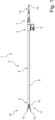
- a medical endoscopic instrument 1 comprises a shaft 2 and an instrument insert 10.
- the shaft 2 comprises a proximal section 3, an elongated middle section 4 and a distal end section 5.
- the shaft 2 is designed for insertion into dimensioned for an internal body cavity, for example, for insertion into a working channel of an endoscope that is inserted into the internal body cavity during an endoscopic procedure.
- the proximal section 3 of the shaft 2 can, for example, have a rinsing connection 6 and a connecting mechanism 7 for connection to a handle (not shown). By means of the connecting mechanism 7, the handle can be connected to the shaft 2 in a rotatable or rotationally fixed manner.
- a tool 11 is arranged, which in the illustrated embodiment is designed as a pair of scissors with two scissor blades 12, 12' that can be pivoted relative to the distal end portion 5 of the shaft 2.
- the tool 11 is part of the instrument insert 10, which is inserted into the shaft 2 on the distal side.
- the instrument insert 10 further comprises a base 13, which is designed as a fork on the distal side, in which the scissor blades 12, 12' are pivotally mounted.
- the base 13 is inserted into the distal end portion 5 of the shaft 2 and connected to it by a coupling shaft, for which the distal end portion 5 is designed as a sleeve, as explained below by way of example.
- a pull rod 14 is arranged to be displaceable in the longitudinal direction of the shaft 10.
- the proximal end of the pull rod 14 is formed by a connecting element, for example a ball 15, which can be connected to a movable part of the handle (not shown) in order to displace the pull rod 14 in the longitudinal direction by actuating the movable part of the handle.
- the pull rod 14 can transmit both tensile and thrust forces in the longitudinal direction of the shaft 10.
- the pull rod 14 is pivotally connected to the scissor blades 12, 12' and also forms part of the instrument insert 10. By displacing the pull rod 14 in the proximal or distal direction, the scissor blades 12, 12' can be opened or closed.
- the shaft 2 is designed as a metallic shaft tube enclosed by an electrically insulating sheath 8. For example, electrical connections for HF voltage can be arranged on the handle or on the shaft 2.
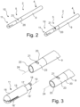
- Fig. 2 shows a shaft 2 according to a further embodiment of the invention in a partial view seen obliquely from the distal direction.
- the middle section 4 of the shaft is formed by a metallic shaft tube 9; the casing 8 (see Fig. 1 ) is not shown.
- the distal end section 5 of the shaft 2 is designed as a sleeve 20, which forms part of a coupling for the detachable connection of the instrument insert 10 to the shaft 2.
- the sleeve 20 has two transverse slots 21, 21' arranged opposite one another, each extending in the circumferential direction, of which Fig. 2 and 3 only the upper transverse slot 21 is visible.
- the terms "upper” as well as “horizontal” and “vertical” refer here and below to the position of the instrument shown in the figures; however, the endoscopic instrument may assume any other position during use.
- the sleeve 20 is elastically deformable at least in the area of the transverse slots 21, 21', so that the sleeve can assume different cross-sectional shapes in the radial direction due to the action of external forces. In the area of the transverse slots 21, 21', the sleeve 20 thus has an elastically deformable cross-sectional profile.
- the sleeve 20 has a mounting shape, while in the right figure of Fig. 2 and 3 has a working shape.
- the sleeve 20 is firmly connected to the shaft tube 9 on the proximal side or can be formed integrally with the shaft tube 9, so that an outer contour of the shaft tube 9 merges smoothly into that of the sleeve 20.
- the sleeve 20 has a largely unchanging cross-sectional shape, approximately corresponding to the circular or oval cross-section of the shaft tube 9, for example.
- the sleeve 20 is elastically deformable and, if no external force is applied, assumes the working shape or is elastically prestressed into the working shape.
- the working shape (right-hand illustration of the sleeve 20) is circular or broadly oval, ie with a horizontally directed main axis.
- the sleeve 20 can be deformed such that it assumes the assembly shape, which in the example shown is highly oval, i.e., has a vertically directed main axis (left-hand illustration of the sleeve 20).
- the sleeve 20 is preferably made of metallic glass, which enables both high strength and high elasticity.
- the instrument insert 10 has a tool 11, which in the illustrated example is designed as a grasping forceps comprising a fixed jaw part 16, which is firmly connected to the base 13 of the tool, and a movable jaw part 16', which is pivotally connected to the base 13.
- a proximal end region of the base 13 is designed as a coupling shaft 17, at the proximal end of which, opposite one another in the vertical direction, two cams 18, 18' are arranged, each projecting radially beyond the surface of the coupling shaft 17.
- the instrument insert 10 further comprises a pull rod (not shown), which is passed through the coupling shaft 17 and the base 13 and is connected to the movable jaw part 16' and which is dimensioned for insertion into the shaft 2 of the endoscopic instrument 1 up to its proximal end.
- a pull rod (not shown), which is passed through the coupling shaft 17 and the base 13 and is connected to the movable jaw part 16' and which is dimensioned for insertion into the shaft 2 of the endoscopic instrument 1 up to its proximal end.
- the cams 18, 18' are designed to correspond to the transverse slots 21, 21' of the sleeve 20, so that the cams 18, 18' can engage in the transverse slots 21, 21' when the sleeve 20 has the working shape (right illustration in Fig. 2 and 3 , where in the right figure in Fig. 2 the cam 18 engaging in the transverse slot 21 is exaggerated).
- the assembly form of the sleeve 20 left illustration of the shaft 2 in Fig.
- the inner width of the sleeve 20 in the region of the transverse slots 21, 21' in the vertical direction is greater than the diameter measured in the vertical direction of the engagement structure formed by the two cams 18, 18', ie the vertical distance between the outer sides of the cams 18, 18'; in the assembled form, the cams 18, 18' can therefore no longer both engage in the transverse slots 21, 21' at the same time.
- the coupling shaft 17 can be inserted into the sleeve 20 until the cams 18, 18' are level with the transverse slots 21, 21' in the axial direction. If necessary, the cams 18, 18' can be brought into corresponding angular positions in the transverse slots 21, 21' by rotating the coupling shaft 17 about its longitudinal axis. The transverse slots 21, 21' are then only lifted off the cams 18, 18' in the radial direction. If the lateral force is then stopped, the cams 18, 18' engage in the transverse slots 21, 21'. In this state, the coupling shaft 17 and thus the instrument insert 10 are held firmly at the distal end of the shaft 2.
- transverse slots 21, 21' and the cams 18, 18' can limit or prevent axial play, just as it can potentially result in a non-rotatable connection.
- the sleeve 20 can be returned to its assembly position, so that the sleeve 20 is lifted off the cams 18, 18' in the area of the transverse slots 21, 21', and the coupling shaft 17 can be pulled out of the sleeve 20 in the axial direction.
- a longitudinal axis 19 of the base 13 and the coupling shaft 17 in the assembled state is aligned with a longitudinal axis 24 of the shaft 2 and the sleeve 20, and the tool 11 is arranged in a distal extension of the shaft 2.
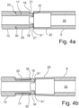
- FIG. 4a and 4b The coupling formed by the coupling shaft 17 and the sleeve 20 is shown in open and closed states, respectively, in a vertical longitudinal section.
- Fig. 4a It is shown that the coupling shaft 17 is inserted into the sleeve 20.
- the sleeve 20 is expanded in the vertical direction via proximal-side run-on bevels 31, 31' of the cams 18, 18'. This facilitates the insertion of the coupling shaft 17 into the sleeve 20; in addition, a lateral pressure force can be exerted on the pressure points 23, 23' to achieve and hold the assembly shape (see above).
- a lateral pressure force can be exerted on the pressure points 23, 23' to achieve and hold the assembly shape (see above).
- Fig. 4b the sleeve 20 is shown in the working form, which the sleeve 20 after reaching the Fig. 4a shown position by an elastic restoring force and, if applicable, by the elimination of the lateral compressive force.
- the cams 18, 18' engage in the transverse slots 21, 21'
- the sleeve 20 engages, with the areas distally adjacent to the transverse slots 21, 21', in the undercut formed by a distal-side step 32, 32' of the cams 18, 18'.
- the coupling shaft 17 and thus the base 13 of the instrument insert 10 are held firmly on the shaft 2.
- an axial position of the base 13 relative to the shaft 2 is determined by the step 30 of the base 13, which acts as a stop, and the distal side of the cams 18, 18'.
- a rotational position of the base 13 relative to the shaft 2 can be determined by the extension of the cams 18, 18' in the circumferential direction in cooperation with a corresponding extension of the transverse slots 21, 21'.
- the sleeve 20 rests with an engagement section, in particular at the distal end, in a vertical direction against the coupling shaft 17. This makes it possible to achieve a connection between the base 13 and the shaft 2 that is rigid against corresponding bending loads.
- the base 13 with the coupling shaft 17 as well as the sleeve 20 and the shaft tube 9 form a longitudinally continuous interior space 25 through which the pull rod (not shown) with which the tool 11 can be actuated is passed.
- the shaft tube 9 has a greater wall thickness than the sleeve 20, but an outer contour that merges smoothly into the outer contour of the sleeve.
- the sleeve 20 can be designed in one piece with the shaft tube 9.
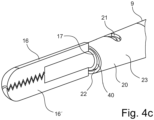
- Fig. 4c The coupling is shown in a partially sectioned oblique view in the closed state. As shown in Fig. 4c As can be seen, in the area of the pressure point 23 between an outer surface of the coupling shaft 17 and an inner surface of the sleeve 20 there is a cavity 40 in order to be able to compress the sleeve 20 sufficiently so that the cams 18, 18' can be released from the transverse slots 21, 21'.
- the coupling is rigidly designed to withstand bending loads in the horizontal direction in that the distal end surface 22 of the sleeve rests against the step 30 of the base 13 and is held by the distal-side step 32, 32' of the cams 18, 18', which each rests against the distal side of the respective transverse slot 21, 21'; for this purpose, the respective sections of the sleeve 20 and the coupling shaft 17 are matched to one another with close tolerance in terms of their length.
- the pull rod and the mechanism for pivoting the movable jaw part 16' are in Fig. 4c not shown.
- Fig. 5 In a simplified schematic representation, the clutch is in the closed state, ie according to Fig. 4b , also shown in a vertical longitudinal section, with several cross sections indicated for clarity.
- the closed state of the coupling in which the cross-sectional shape of the sleeve 20 is the working shape, the sleeve 20 engages with its distally adjacent regions to the transverse slots 21, 21' in the undercut formed by the distal step 32, 32' of the cams 18, 18', and the cams 18, 18' engage in the transverse slots 21, 21' (see Fig. 4a and 4b ).
- the closed state of the coupling in which the cross-sectional shape of the sleeve 20 is the working shape
- the sleeve 20 engages with its distally adjacent regions to the transverse slots 21, 21' in the undercut formed by the distal step 32, 32' of the cams 18, 18', and the cams 18, 18' engage in the transverse slots 21, 21' (see Fig. 4a and 4
- the sleeve 20 has a broad oval cross-section 26 in the area of the transverse slots 21, 21' in the working form.
- the shaft tube 9, which adjoins the sleeve 20 on the proximal side, has a circular cross-section 27.
- the base 13 also has a circular cross-section 33.
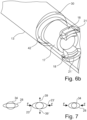
- FIG. 6a and 6b Two variants of the previously described embodiment are shown, each in a partially transparent view.
- Fig. 6a In the variant shown, the coupling shaft 17 is extended in the proximal direction so that, when the coupling is closed, it projects through the sleeve 20 into the shaft 9.
- the proximal extension 41 of the coupling shaft 17 rests tightly against the inside of the shaft 9, without play. This allows the coupling to be additionally stiffened, particularly in the horizontal direction.
- the coupling shaft 17 has a support section 42 distal to the step 30 of the base 13, which has a cross-sectional profile that is adapted to the inner contour of the sleeve 20 in the working form and rests against it without play.
- the support section 42 has only a short longitudinal extent so as not to hinder deformation of the sleeve 20 for releasing the cams 18, 18' from the transverse slots 21, 21'. This also allows increased rigidity to be achieved in the horizontal direction, wherein the actuating profile 42 can represent an additional anti-twist device between the shaft 9 and the base 13.
- FIG. 7 The opening of the coupling is symbolically represented by the cross-sectional contours.
- the cross-sectional contour 28 of the sleeve 20 is flattened in the area of a holding structure such that it engages with an undercut of the coupling shaft 17, which is shown with a circular cross-sectional contour 34.
- the cross-sectional profile can be spread in the intermediate circumferential areas in the direction of the arrows 39, 39', thus reducing the flattening of the cross-section (middle illustration), until finally the holding structure of the sleeve is lifted out of the undercut of the coupling shaft 17 and the coupling is opened (right illustration).
- the coupling shaft 17 has a cross-section which has approximately the shape of an equilateral triangle, the corners of the triangle being designed as cams 18, 18', 18", which in the working form each engage in openings 29, 29', 29" of the sleeve 20, which are offset from one another in the circumferential direction by 120°.
- the coupling shaft 17 has a deformable cross-sectional profile such that the cams 18, 18', 18" can be pressed inward.
- the coupling can be released by manually exerting a force F on the cams 18, 18', 18" in the direction of the arrows, so that the coupling shaft 17 is converted into the assembly form in which the cams 18, 18', 18" no longer engage the openings 29, 29', 29" and the coupling shaft 17 can be pulled out of the sleeve 20 in the axial direction (not shown).
- a force F in the range of one or a few N, for example approximately 5 N, may be sufficient for this purpose.
- the cams 18, 18', 18" each have run-on bevels 35 on both sides in the circumferential direction.
- This provides the option, alternatively or in addition to manually exerting the lateral pressure force, of rotating the sleeve 20 about the longitudinal axis relative to the coupling shaft 17, whereby the cams 18, 18', 18" are pressed in radially via the respective run-on bevels 35 and thus also come out of engagement with the openings 29, 29', 29".
- the coupling can also be released in this way.
- the sleeve 20 has a deformable cross-sectional profile.
- the sleeve 20 can be deformed by exerting lateral force on pressure points located in the circumferential direction between the openings 29, 29', 29", as well as by rotating the sleeve 20 relative to the coupling shaft 17, so that the cams 18, 18', 18" are released from the openings 29, 29', 29" (not shown).
- the base 13 or the coupling shaft 17 further comprises a resilient tab 36 which carries a locking lug 37 which, when the coupling is closed, engages in an opening 38 of the sleeve 20 and which has no run-on bevels in the circumferential direction (see Fig. 8b, 8c ).
- This therefore serves as an anti-twist device to prevent accidental release of the coupling due to torque generated during use of the instrument.
- the locking lug 37 must be pressed in by applying a radial force F', in order to then rotate the coupling shaft 17 about its longitudinal axis relative to the sleeve 20.
Landscapes
- Health & Medical Sciences (AREA)
- Life Sciences & Earth Sciences (AREA)
- Surgery (AREA)
- General Health & Medical Sciences (AREA)
- Public Health (AREA)
- Veterinary Medicine (AREA)
- Nuclear Medicine, Radiotherapy & Molecular Imaging (AREA)
- Animal Behavior & Ethology (AREA)
- Molecular Biology (AREA)
- Engineering & Computer Science (AREA)
- Biomedical Technology (AREA)
- Heart & Thoracic Surgery (AREA)
- Medical Informatics (AREA)
- Biophysics (AREA)
- Radiology & Medical Imaging (AREA)
- Physics & Mathematics (AREA)
- Pathology (AREA)
- Optics & Photonics (AREA)
- Ophthalmology & Optometry (AREA)
- Endoscopes (AREA)
- Surgical Instruments (AREA)
Description
- Die vorliegende Erfindung betrifft ein endoskopisches Instrument, insbesondere ein endoskopisches medizinisches Instrument. Bei einem endoskopischen Eingriff wird durch eine natürliche oder eine mit Hilfe einer Inzision geschaffene künstliche Körperöffnung ein endoskopisches Instrumentarium, das insbesondere ein Endoskop und ein oder mehrere endoskopische Instrumente umfassen kann, zu einem im Körperinneren gelegenen Operationsgebiet geführt. Endoskopische Instrumente weisen hierfür einen lang erstreckten Schaft auf, an dessen distalem, d.h. benutzerfernen Ende ein Werkzeug angeordnet ist, das von einem am proximalen, d.h. benutzernahen Ende des Schafts angeordneten Handgriff über ein im Schaft angeordnetes langerstrecktes Übertragungselement betätigt werden kann. Der Schaft kann starr oder flexibel ausgebildet sein. Der Handgriff verbleibt bei einem endoskopischen Eingriff außerhalb der Körperöffnung, während der Schaft mit dem Werkzeug durch die Körperöffnung eingeführt wird.
- Gemäß einer verbreiteten Bauart weisen endoskopische Instrumente einen Instrumenteneinsatz auf, der an seinem distalen Ende das Werkzeug trägt und der auch das Übertragungselement, etwa eine Zugstange, umfassen kann. Der Instrumenteneinsatz, der auch als Arbeitseinsatz bezeichnet wird, ist lösbar mit dem Schaft des Instruments verbunden. Dabei kann es vorgesehen sein, dass Instrumenteneinsätze mit unterschiedlichen Werkzeugen mit dem Schaft verbunden und von diesem wieder gelöst werden können. Insbesondere kann das Instrument zur Reinigung und/oder Sterilisation zerlegbar sein, wobei der Instrumenteneinsatz von dem Schaft gelöst wird; ferner kann der Handgriff vom Schaft getrennt werden.
- Für die lösbare Verbindung des Instrumenteneinsatzes mit einem distalen Endabschnitt des Schafts ist insbesondere eine Verbindung nach Art einer Bajonettverbindung bekannt. Endoskopische Instrumente, bei denen ein Werkzeug bzw. ein Instrumenteneinsatz nach Art einer Bajonettverbindung mit dem distalen Ende eines Schafts verbindbar ist, sind beispielsweise in
EP 0 688 187 B1 undDE 197 22 062 A1 offenbart. Dabei stellt eine Zugstange, über die das Werkzeug betätigt werden kann, zugleich eine Verdrehsicherung dar, um den Bajonetteingriff aufrecht zu erhalten. Hierfür ist die Zugstange im proximalen Bereich abgeflacht, wobei zwei Klemmstücke in die Abflachung eingreifen, so dass ein Verdrehen der Zugstange relativ zu einem Rohrschaft des Instruments verhindert wird.US 2012/259325 A1 offenbart ein endoskopisches Instrument gemäß der Präambel.US 2021/275203 A1 ,US 2017/360462 A1 undUS 2002/111534 A1 offenbaren weitere ähnliche endoskopische Instrumente. - Gattungsgemäße medizinische endoskopische Instrumente werden von KARL STORZ SE & Co. KG beispielsweise unter den Bezeichnungen "ClickLine®" sowie "RoBi®" vertrieben.
- Es ist Aufgabe der vorliegenden Erfindung, ein endoskopisches Instrument anzugeben, insbesondere ein endoskopisches medizinisches Instrument, wobei ein Instrumenteneinsatz durch einen Verbindungsmechanismus lösbar mit einem distalen Endabschnitt eines Schafts des Instruments verbunden ist, wobei insbesondere eine Verbindung ohne Verdrehsicherung oder mit einer alternativen Verdrehsicherung besteht.
- Diese Aufgabe wird durch ein endoskopisches Instrument gemäß Anspruch 1 gelöst. Vorteilhafte Weiterbildungen der Erfindung ergeben sich aus den Unteransprüchen.
- Ein erfindungsgemäßes endoskopisches Instrument ist insbesondere ein medizinisches endoskopisches Instrument, beispielsweise ein chirurgisches endoskopisches Instrument zur Durchführung von minimal-invasiven chirurgischen Eingriffen. Das endoskopische Instrument umfasst einen lang erstreckten Schaft, der insbesondere zur Einführung in einen körperinneren Hohlraum eines menschlichen oder tierischen Körpers ausgebildet ist. Der Schaft ist vorzugsweise starr oder im Wesentlichen starr ausgebildet und weist ein langerstrecktes Schaftrohr auf, das einen Außenschaft des Instruments darstellen kann; andererseits kann der Schaft aber auch flexibel ausgebildet sein. Weiter umfasst das endoskopische Instrument einen Instrumenteneinsatz, der mit einem distalen Endabschnitt des Schafts lösbar verbunden ist, insbesondere am distalen Ende des Schafts lösbar gehalten ist.
- Der Instrumenteneinsatz umfasst ein Werkzeug, das insbesondere zur Ausführung endoskopischer Manipulationen in dem körperinneren Hohlraum ausgebildet ist, sowie eine vorzugsweise schaftförmige Basis, die auch als Gabel bezeichnet wird. Das Werkzeug kann zwei miteinander zusammenwirkende Werkzeugelemente aufweisen, von denen mindestens eines relativ zur Basis beweglich ist. Das Werkzeug kann beispielsweise eine chirurgische Schere oder Greifzange sein, die ein oder zwei relativ zueinander schwenkbare, als Scheren- bzw. Maulteile ausgebildete Werkzeugelemente aufweist, wovon mindestens eines gelenkig an der Basis gelagert ist. Das Werkzeug kann über ein langerstrecktes Übertragungselement betätigbar sein, das innerhalb des Schafts bis zu dessen proximalem Ende verläuft und welches beispielsweise als Zugstange ausgebildet sein kann, die gelenkig mit dem mindestens einen beweglichen Werkzeugelement verbunden ist. Das Übertragungselement kann ein Teil des Instrumenteneinsatzes sein.
- Erfindungsgemäß ist der distale Endabschnitt des Schafts des endoskopischen Instruments als Hülse ausgebildet, und ein proximaler Endbereich der Basis des Instrumenteneinsatzes ist als Kupplungsschaft ausgebildet, wobei der Kupplungsschaft zum lösbaren Verbinden des Instrumenteneinsatzes mit dem Schaft lösbar in der Hülse gehalten ist. Alternativ erfindungsgemäß kann der proximale Endbereich der Basis des Instrumenteneinsatzes als Hülse und der distale Endabschnitt des Schafts als Kupplungsschaft ausgebildet sein, der zum lösbaren Verbinden des Instrumenteneinsatzes mit dem Schaft lösbar in der Hülse gehalten ist.
- Die Hülse, die auch als Kupplungshülse bezeichnet werden kann, und der Kupplungsschaft, der auch als Kupplungszapfen bezeichnet werden kann, bilden somit eine Kupplung zum lösbaren Verbinden des Instrumenteneinsatzes mit dem Schaft und sind dementsprechend zum Zusammenwirken miteinander ausgestaltet.
- Wenn der Instrumenteneinsatz mittels der durch die Hülse und den Kupplungsschaft gebildeten Kupplung mit dem Schaft verbunden ist, so sind die Basis und das Werkzeug vorzugsweise in einer distalseitigen Verlängerung einer Längsachse des Schafts angeordnet. Insbesondere kann die Basis eine Längsachse aufweisen, die dann, wenn der Instrumenteneinsatz mit dem Schaft verbunden ist, mit der Längsachse des Schafts zumindest näherungsweise fluchtet. Der Kupplungsschaft ist vorzugsweise als Hohlschaft bzw. Hohlrohr ausgebildet, durch welches das Übertragungselement hindurch verlaufen kann. In dem Fall, dass der distale Endabschnitt des Schafts als Hülse ausgebildet ist, kann die Hülse eine distale Verlängerung oder einen distalen Endabschnitt eines Schaftrohrs darstellen, wobei das Übertragungselement im Inneren des Schaftrohrs geführt ist.
- Weiter erfindungsgemäß weist die Hülse und/oder der Kupplungsschaft zumindest abschnittsweise ein Querschnittsprofil auf, das zum Lösen des Kupplungsschafts aus der Hülse reversibel veränderbar ist. Die Hülse und/oder der Kupplungsschaft ist erfindungsgemäß somit, auf die Längsachse des Schafts bzw. der Basis bezogen, zumindest in einem Abschnitt mit einem veränderbaren Querschnittsprofil ausgebildet, und die Hülse und der Kupplungsschaft sind derart ausgestaltet, dass durch Veränderung des Querschnittsprofils der Kupplungsschaft aus der Hülse lösbar ist. Die Veränderung des Querschnittsprofils kann dabei eine Änderung der Form des Querschnitts sein, also eine Verformung des Querschnittsprofils bzw. der Querschnittskontur, und/oder eine Änderung der Dimensionen des Querschnitts, also eine Änderung der Größe bzw. des Radius des Querschnittsprofils bzw. der Querschnittskontur. Insbesondere kann die Hülse und/oder der Kupplungsschaft reversibel verformbar sein und derart ausgestaltet sein, dass durch eine Querschnittsverformung der Kupplungsschaft aus der Hülse gelöst werden kann. Die Querschnittsverformung, durch die die Kupplung gelöst wird, kann insbesondere durch eine von außen einwirkende Kraft bewirkt werden. Die von außen einwirkende Kraft kann manuell von einem Benutzer ausübbar sein, etwa eine in radialer Richtung auf die Hülse ausgeübte Druckkraft. Dabei ist eine Steifigkeit der Hülse bzw. des Kupplungsschafts insbesondere derart gewählt, dass die Drucckraft durch den Benutzer mit den Fingern einer Hand bequem ausgeübt werden kann, jedoch durch eine Berührung mit körperinneren Strukturen, wie etwa einer Wand des körperinneren Hohlraums, in der Regel nicht aufgebracht werden kann.
- Der Schaft kann mit einer Umhüllung versehen sein, durch die beispielsweise eine Schutzfunktion oder eine elektrische Isolierung bereitgestellt wird. In dem Fall, dass der Schaft ein starres Schaftrohr umfasst, besteht das Schaftrohr vorzugsweise aus einem metallischen Material, etwa aus Edelstahl, und die Umhüllung aus einem Kunststoffmaterial, welches etwa in Form eines Schrumpfschlauchs auf der Außenseite des Schaftrohrs aufliegen kann. Das endoskopische Instrument kann beispielsweise ein elektrochirurgisches Instrument sein.
- Das endoskopische Instrument kann ferner einen Handgriff umfassen mit einem beweglichen Teil, der mit einem proximalen Ende des Übertragungselements verbindbar sein kann, so dass das Werkzeug durch Betätigung des beweglichen Teils mittels einer Bewegung des Übertragungselements relativ zum Schaft betätigbar ist. Vorzugsweise ist der Handgriff mit einem proximalen Ende des Schafts lösbar verbindbar.
- Dadurch, dass die Hülse und/oder der Kupplungsschaft durch reversible Änderung des Querschnittsprofils voneinander lösbar sind, wird es auf einfache Weise ermöglicht, die Kupplung zu lösen und somit den Instrumenteneinsatz vom Schaft zu lösen. Insbesondere kann die Querschnittsänderung eine Querschnittsverformung sein, die durch eine manuelle Krafteinwirkung von einem Benutzer bewirkt werden kann, wodurch ein besonders einfaches Trennen des Instrumenteneinsatzes vom Schaft ermöglicht werden kann. Zudem kann dadurch, dass zum Lösen der Kupplung eine Veränderung des Querschnittsprofils erforderlich ist, ein sicheres Halten des Instrumenteneinsatzes am Schaft ohne eine zusätzliche Verdrehsicherung ermöglicht werden. Somit kann ein Lösen des Instrumenteneinsatzes vom Schaft auf einfache Weise ermöglicht und zugleich ein unbeabsichtigtes Lösen sicher verhindert werden. Dadurch, dass das endoskopische Instrument zerlegbar ist und der Instrumenteneinsatz vom Schaft lösbar ist, können die Reinigung und Sterilisation des Instruments sowie ein Wechsel des Instrumenteneinsatzes erleichtert werden.
- Im Folgenden wird die Erfindung insbesondere anhand von Ausführungsformen erläutert, bei denen der distale Endabschnitt des Schafts eine Hülse umfasst bzw. als solche ausgebildet ist, und wobei der Instrumenteneinsatz einen in die Hülse einführbaren Kupplungsschaft umfasst. Es versteht sich jedoch, dass jeweils auch, in entsprechend umgekehrter Anordnung, der Kupplungsschaft dem Schaft des endoskopischen Instruments und die Hülse dem Instrumenteneinsatz zugeordnet sein kann.
- Das erfindungsgemäße endoskopische Instrument kann derart ausgebildet sein, dass zum Schließen der Kupplung ebenfalls eine reversible Veränderung des Querschnittsprofils erforderlich ist. Insbesondere kann der Kupplungsschaft zum Verbinden des Instrumenteneinsatzes mit dem Schaft in die Hülse einführbar sein, wobei zum Schließen der Kupplung eine Veränderung des Querschnittsprofils, etwa eine Querschnittsverformung oder Größenänderung des Querschnitts, erfolgen kann, die umgekehrt zu der zum Lösen der Kupplung erforderlichen Änderung sein kann. Hierdurch kann auf einfache Weise eine feste und sichere Verbindung des Instrumenteneinsatzes mit dem Schaft erreichbar sein.
- Erfindungsgemäß ist die reversible Veränderung des Querschnittsprofils zum Lösen des Kupplungsschafts aus der Hülse eine reversible Verformung des Querschnittsprofils der Hülse und/oder des Kupplungsschafts, insbesondere eine elastische Verformung. Die Hülse bzw. der Kupplungsschaft ist somit zum Lösen der Verbindung elastisch verformbar ausgebildet. Zum Lösen der Verbindung des Instrumenteneinsatzes mit dem Schaft ist daher eine Querschnittsverformung der Hülse bzw. des Kupplungsschafts gegen eine elastische Rückstellkraft erforderlich. Insbesondere kann die Hülse bzw. der Kupplungsschaft zum Halten des Kupplungsschafts in der Hülse vorgespannt sein. Dies hat den Vorteil, dass ohne Einwirkung einer äußeren Kraft die Kupplung zwangsgeschlossen ist und ferner der Kupplungsschaft besonders sicher in der Hülse gehalten werden kann; weiterhin kann hierdurch das Schließen der Kupplung erleichtert werden.
- Insbesondere kann das Querschnittsprofil ein im Wesentlichen geschlossenes Querschnittsprofil sein, d.h. das reversibel veränderbare Querschnittsprofil ist in Umfangsrichtung im Wesentlichen geschlossen ausgebildet, beispielsweise ringförmig geschlossen. Die Hülse und/oder der Kupplungsschaft weist somit gemäß dieser Ausführungsform zumindest abschnittsweise ein im Wesentlichen geschlossenes Querschnittsprofil auf, das zum Lösen des Kupplungsschafts aus der Hülse reversibel veränderbar ist, insbesondere durch elastische Verformung reversibel veränderbar ist. "Im Wesentlichen geschlossen" bedeutet hier und im Folgenden insbesondere, dass der Abschnitt der Hülse bzw. des Kupplungsschafts, in dem das Querschnittsprofil reversibel verformbar ist, zumindest einen Teilabschnitt umfasst, in dem das Querschnittsprofil umlaufend geschlossen ist, beispielsweise ringförmig geschlossen. Hierdurch können eine besonders feste Verbindung und eine hohe Biegebelastbarkeit der Verbindung des Instrumenteneinsatzes mit dem distalen Endbereich des Schafts erreichbar sein.
- Gemäß der Erfindung weist die Hülse eine erste Haltestruktur und der Kupplungsschaft eine zweite Haltestruktur auf, die mit der ersten Haltestruktur zum Halten des Kupplungsschafts in der Hülse zusammenwirkt. Die erste und die zweite Haltestruktur sind somit derart zum Zusammenwirken ausgestaltet, dass der Kupplungsschaft in der Hülse gehalten ist und insbesondere gegen Lösen in axialer Richtung gesichert ist, so dass der Instrumenteneinsatz mit dem Schaft verbunden ist. Weiterhin ist gemäß dieser Ausführungsform die Hülse durch reversible, insbesondere elastische Querschnittsverformung aus einer Arbeitsform, in der die erste Haltestruktur und die zweite Haltestruktur zum Halten des Kupplungsschafts in der Hülse zusammenwirken, in eine Montageform, in der die erste Haltestruktur und die zweite Haltestruktur voneinander gelöst sind, überführbar. Alternativ oder zusätzlich kann der Kupplungsschaft durch reversible, insbesondere elastische Querschnittsverformung aus einer Arbeitsform, in der die erste und die zweite Haltestruktur zum Halten des Kupplungsschafts in der Hülse zusammenwirken, in eine Montageform, in der die erste und die zweite Haltestruktur voneinander gelöst sind, überführbar sein. Zum Halten der Verbindung weisen die Hülse bzw. der Kupplungsschaft somit eine jeweilige Arbeitsform auf, in der miteinander korrespondierende Haltestrukturen zum Halten zusammenwirken, wobei zum Lösen der Verbindung die Hülse und/oder der Kupplungsschaft durch reversible Verformung in eine Montageform gebracht werden können. Insbesondere ist die erste und/oder die zweite Haltestruktur in der jeweiligen Arbeitsform zum Zusammenwirken mit der jeweils korrespondierenden Haltestruktur angeordnet und in der Montageform von dieser getrennt angeordnet. Wenn die Hülse bzw. der Kupplungsschaft durch reversible Verformung in die Montageform überführt worden ist, ist der Kupplungsschaft somit aus der Hülse entnehmbar. Zum Einführen des Kupplungsschafts in die Hülse, d.h. zum Verbinden des Instrumenteneinsatzes mit dem Schaft bzw. zum Schließen der Kupplung kann die Hülse und/oder der Kupplungsschaft aus der Montageform in die Arbeitsform bringbar sein. Die Hülse und/oder der Kupplungsschaft kann insbesondere im Bereich der Haltestruktur einen geschlossenen Querschnitt haben.
- Dadurch, dass die Hülse eine erste Haltestruktur und der Kupplungsschaft eine zweite Haltestruktur aufweisen, wobei die zweite mit der ersten Haltestruktur zum Halten des Kupplungsschafts in der Hülse zusammenwirkt, kann, wenn die Hülse bzw. der Kupplungsschaft die Arbeitsform hat, ein sicheres Halten des Instrumenteneinsatzes am Schaft und damit ein sicheres Arbeiten mit dem endoskopischen Instrument ermöglicht werden. Ferner kann, wenn die Hülse bzw. der Kupplungsschaft die Montageform hat, ein einfaches Trennen des Instrumenteneinsatzes vom Schaft des Instruments ermöglicht werden, beispielsweise zur Reinigung oder für einen Wechsel des Instrumenteneinsatzes. In dem Fall, dass die Hülse bzw. der Kupplungsschaft durch elastische Querschnittsverformung aus der Arbeitsform in die Montageform überführbar ist, kann erreicht werden, dass ohne Einwirkung von außen die Arbeitsform erhalten und somit die Kupplung sicher geschlossen bleibt, dass durch eine temporäre Querschnittsverformung durch äußere Krafteinwirkung gegen eine elastische Rückstellkraft die Kupplung geöffnet werden kann, und dass, wenn keine äußere Kraft mehr einwirkt, durch elastische Rückverformung das Querschnittsprofil wieder die Arbeitsform einnimmt.
- Der Schaft kann in vorteilhafter Weise einen Querschnitt mit einer Außenkontur haben, die der Querschnittskontur der Hülse in der Arbeitsform entspricht, oder beispielsweise einen kreisförmigen Querschnitt, der in einem Übergangsabschnitt der Hülse und/oder des Schafts in den Querschnitt der Hülse in der Arbeitsform übergeht. Sofern der Schaft starr ausgebildet ist, kann insbesondere ein starres Schaftrohr, das einen Außenschaft bildet, einen Querschnitt mit einer solchen Kontur haben, die der Querschnittskontur der Hülse in der Arbeitsform entspricht oder in diese übergeht. Insbesondere kann der Schaftrohr eine größere Wandstärke als die Hülse haben, jedoch eine Querschnittskontur, die der Querschnittskontur der Hülse in der Arbeitsform entspricht oder im Übergangsabschnitt in diese übergeht; das Schaftrohr kann beispielsweise ein Profilrohr mit einem entsprechenden Querschnittsprofil sein. Hierdurch wird es ermöglicht, dass der Schaft des endoskopischen Instruments eine weitgehend glatte Außenkontur hat.
- Gemäß der Erfindung erstreckt sich die erste Haltestruktur in Umfangsrichtung über einen oder mehrere Teil-Winkelbereiche der Hülse .
- Die erste Haltestruktur nimmt somit, von der Längsachse der Hülse bzw. des Kupplungsschafts aus gesehen, einen oder mehrere Teil-Winkelbereiche ein, wobei jedoch mindestens ein freier Winkelbereich nicht von der ersten Haltestruktur eingenommen wird. Alternativ oder zusätzlich kann es vorgesehen sein, dass sich die zweite Haltestruktur, auf die Längsachse bezogen, über einen oder mehrere Teil-Winkelbereiche des Kupplungsschafts erstreckt, wobei mindestens ein freier Winkelbereich nicht von der zweiten Haltestruktur eingenommen wird. Weiter weist die Hülse mindestens einen Druckpunkt zum Verformen des Querschnittsprofils der Hülse aus der Arbeitsform in die Montageform auf, wobei der mindestens eine Druckpunkt außerhalb der Teil-Winkelbereiche der ersten bzw. der zweiten Haltestruktur gelegen ist, d.h. in dem mindestens einen freien Winkelbereich. Der mindestens eine Druckpunkt ist somit gegenüber der ersten bzw. der zweiten Haltestruktur versetzt und kann beispielsweise etwa in der Mitte eines freien Winkelbereichs angeordnet sein. Vorzugsweise ist der mindestens eine Druckpunkt in einem Winkelbereich gelegen, in dem das Querschnittsprofil der Hülse eine konvexe Form hat. In besonders vorteilhafter Weise kann das Querschnittsprofil der Hülse in mindestens einem Abschnitt im Bereich der ersten Haltestruktur ringförmig geschlossen und umlaufend konvex ausgebildet sein. Die Hülse und der Kupplungsschaft sind insbesondere derart ausgebildet, dass durch Einwirkung einer Druckkraft von außen in radialer Richtung das Querschnittsprofil der Hülse in einer solchen Weise verformt wird, dass die erste Haltestruktur in radialer Richtung angehoben und dadurch von der zweiten Haltestruktur getrennt wird und nicht mehr mit der zweiten Haltestruktur zum Halten des Kupplungsschafts in der Hülse zusammenwirkt. Hierfür kann zwischen einer äußeren Oberfläche des Kupplungsschafts und einer inneren Oberfläche der Hülse im Bereich des Druckpunkts ein Hohlraum vorgesehen sein, um die Hülse im Bereich des Druckpunkts ausreichend zusammendrücken zu können.
- Gemäß einer Ausführungsform der Erfindung ist die Arbeitsform der Hülse eine abgeflachte oder abgeplattete Form, etwa eine elliptische oder ovale Form, wobei in den Scheitelpunkten der abgeflachten Querschnittsform jeweils ein Druckpunkt angeordnet ist und somit zwei, bezüglich der Längsachse zumindest näherungsweise einander gegenüberliegende Druckpunkte vorgesehen sind. Der Querschnitt der Hülse hat somit zumindest im Bereich der ersten Haltestruktur eine umlaufend konvexe Außenkontur, wobei im Bereich der einander gegenüberliegenden Scheitelpunkte die Außenkontur jeweils eine größere Krümmung aufweist als in den dazwischenliegenden Bereichen, und wobei die Druckpunkte näherungsweise in den Bereichen der größeren Krümmung angeordnet sind. Durch Ausüben einer Druckkraft auf die Druckpunkte kann die abgeflachte Form von den Scheitelpunkten her zusammengedrückt werden, so dass die zwischen den Scheitelpunkten liegenden flacheren Bereiche, in denen die erste oder die zweite Haltestruktur angeordnet ist, zumindest teilweise nach außen verlagert werden und dadurch das Querschnittsprofil die Montageform einnimmt, in der die erste von der zweiten Haltestruktur abgehoben ist. Die Montageform kann beispielsweise ebenfalls eine abgeflachte Form sein, wobei die Hauptachse, die die Scheitelpunkte verbindet, gegenüber der Arbeitsform um etwa 90° gedreht ist, kann aber auch eine Kreisform oder eine abgeflachte Form mit derselben Hauptachse wie die Arbeitsform, jedoch mit geringerer Abplattung bzw. Elliptizität sein. Hierdurch kann ein unbeabsichtigtes Lösen sicher verhindert werden und dennoch die Kupplung bequem lösbar sein.
- Alternativ kann die Arbeitsform eine Kreisform sein, wobei die beiden Druckpunkte einander gegenüberliegend angeordnet sind, und die Montageform ist eine abgeflachte, etwa elliptische oder ovale Form, bei der die Druckpunkte in Umfangsrichtung zwischen den Scheitelpunkten, insbesondere etwa mittig zwischen den Scheitelpunkten, liegen. Weiter alternativ kann die Arbeitsform eine abgeflachte Form sein, wobei die Druckpunkte zwischen den Scheitelpunkten angeordnet sind, wobei die Montageform eine abgeflachte Form mit gleicher Hauptachse, jedoch größerer Abplattung bzw. Elliptizität, ist. Auch hierdurch kann ein einfaches Lösen der Kupplung durch manuelle Ausübung einer Druckkraft auf die einander gegenüber liegenden Druckpunkte ermöglicht werden.
- Gemäß einer weiteren Ausführungsform der Erfindung weist die Hülse drei Druckpunkte auf, die bezüglich der Längsachse der Hülse jeweils um etwa 120° gegeneinander versetzt sind, wobei das Querschnittsprofil bzw. die Querschnittskontur ebenfalls vorzugsweise umlaufend konvex ist. Durch Ausübung einer Druckkraft auf die drei Druckpunkte können die jeweils dazwischen liegenden Bereiche der Querschnittsform in radialer Richtung angehoben werden, so dass die erste und die zweite Haltestruktur dort voneinander getrennt werden. Auch hierdurch kann auf einfache Weise ein manuelles Lösen der Verbindung ermöglicht werden, wobei eine besonders hohe Sicherheit gegen ein unbeabsichtigtes Lösen erreichbar ist.
- Vorzugsweise sind die Hülse und/oder der Kupplungsschaft derart ausgebildet, dass diese durch Ausüben einer Druckkraft auf den mindestens einen Druckpunkt mit einem oder mehreren Fingern einer Hand durch einen Benutzer voneinander lösbar sind, wobei die Drucckraft bequem mit den Fingern, jedoch in der Regel nicht durch Berührung mit körperinneren Strukturen aufgebracht werden kann. Insbesondere kann die Druckkraft mit zwei Fingern einer Hand auf zwei gegenüber liegende Druckpunkte oder mit drei Fingern auf drei um 120° versetzte Druckpunkte ausübbar sein. Dabei kann eine Druckkraft beispielsweise im Bereich von etwa 1 bis 30 N, vorzugsweise im Bereich von ca. 3 bis 10 N, insbesondere etwa 5 N, zum Lösen des Kupplungsschafts aus der Hülse geeignet sein.
- Die Hülse bzw. der Kupplungsschaft kann insgesamt oder lediglich in einem oder mehreren Abschnitten das reversibel verformbare Querschnittsprofil aufweisen. Insbesondere kann die Hülse in einem Abschnitt, der bis an ein distales Ende der Hülse reicht, bzw. der Kupplungsschaft in einem Abschnitt, der bis an ein proximales Ende des Kupplungsschafts reicht, zum Lösen des Kupplungsschafts aus der Hülse einen reversibel verformbaren Querschnitt haben. Andererseits kann es beispielsweise auch vorgesehen sein, dass die Hülse bzw. der Kupplungsschaft nur in einem mittleren Abschnitt zum Lösen des Kupplungsschafts von der Hülse verformt wird, während ein proximales und ein distales Ende nicht verformt werden; in diesem Fall sind der bzw. die Druckpunkte im mittleren Abschnitt angeordnet.
- Gemäß einer vorteilhaften Ausführungsform weist der Kupplungsschaft einen Stützabschnitt zur Abstützung eines Endabschnitts der Hülse in der Arbeitsform auf. Der Endabschnitt der Hülse ist in dem Fall, dass die Hülse dem Schaft zugeordnet ist, ein distaler Endabschnitt und in dem Fall, dass die Hülse dem Instrumenteneinsatz zugeordnet ist, ein proximaler Endabschnitt. Der Stützabschnitt kann beispielsweise im ersten Fall im distalen und im zweiten Fall im proximalen Endbereich des Kupplungsschafts angeordnet sein. Der Stützabschnitt weist insbesondere eine Außenkontur auf, die zumindest näherungsweise der Innenkontur der Hülse im entsprechenden Endabschnitt in der Arbeitsform entspricht. Dadurch wird die Hülse in der Arbeitsform in ihrem entsprechenden Endabschnitt abgestützt, so dass die Hülse nur in einem mittleren Abschnitt zum Lösen des Kupplungsschafts von der Hülse verformt werden kann. Hierdurch kann erreicht werden, dass trotz des zur Verformung notwendigen Hohlraums innerhalb der Hülse die Kupplung eine hohe Steifigkeit gegen seitliche Belastung auch in der entsprechenden Richtung aufweist.
- In vorteilhafter Weise kann die erste Haltestruktur als Eingriffsstruktur und die zweite Haltestruktur als zum Eingreifen in die erste Haltestruktur ausgebildetes Eingriffselement ausgebildet sein, oder umgekehrt kann die zweite Haltestruktur als Eingriffsstruktur und die erste Haltestruktur als zum Eingreifen in die zweite Haltestruktur ausgebildetes Eingriffselement ausgebildet sein. Die Eingriffsstruktur weist insbesondere, aus distaler axialer Richtung gesehen, einen Hinterschnitt auf und kann beispielsweise durch einen in Umfangsrichtung verlaufenden Schlitz oder Einstich bzw. durch eine in Umfangsrichtung verlaufende Nut gebildet werden. Das Eingriffselement ist insbesondere in radialer Richtung von der Hülse nach innen bzw. von dem Kupplungsschaft nach außen vorstehend angeordnet und kann insbesondere als Ringbund oder Nocken, beispielsweise als Bajonettelement, ausgebildet sein; das Eingriffselement kann somit, aus proximaler axialer Richtung gesehen, einen Hinterschnitt aufweisen. In der Arbeitsform greift somit das Eingriffselement in die Eingriffsstruktur ein, so dass der Kupplungsschaft in der Hülse gehalten ist. In der Montageform ist das Eingriffselement aus der Eingriffsstruktur gelöst, so dass der Kupplungsschaft aus der Hülse entnehmbar ist. In besonders vorteilhafter Weise kann die Hülse und/oder der Kupplungsschaft zumindest in einem Abschnitt, in dem die Eingriffsstruktur bzw. das Eingriffselement angeordnet ist, ein ggf. bis auf die Eingriffsstruktur selbst geschlossenes Querschnittsprofil haben. Hierdurch kann eine besonders feste, insbesondere eine formschlüssige Verbindung der Basis des Instrumenteneinsatzes mit dem Schaft erreicht werden.
- Gemäß einer Ausführungsform der Erfindung weist die zweite Haltestruktur mindestens einen radial über eine Oberfläche des Kupplungsschafts vorstehenden Nocken auf, und die erste Haltestruktur weist mindestens einen hiermit korrespondierenden Durchbruch oder einen in Umfangsrichtung verlaufenden Schlitz oder auch eine in Umfangsrichtung verlaufende Nut auf, wobei der mindestens eine Nocken zum Eingreifen in den korrespondierenden Durchbruch bzw. Schlitz ausgebildet und angeordnet ist. Der Nocken stellt somit ein Eingriffselement und der Durchbruch bzw. der Schlitz oder die Nut eine entsprechende Eingriffsstruktur dar. Insbesondere kann die Arbeitsform der Hülse und/oder des Kupplungsschafts derart ausgestaltet sein, dass der mindestens eine Nocken in den Durchbruch bzw. Schlitz eingreift und dadurch der Kupplungsschaft in der Hülse gehalten wird, und die Montageform der Hülse und/oder des Kupplungsschafts derart, dass der mindestens eine Nocken nicht in den Durchbruch bzw. Schlitz eingreift, so dass der Kupplungsschaft aus der Hülse lösbar ist. Gemäß einer Variante dieser Ausführungsform greift der mindestens eine Nocken derart in die zweite Haltestruktur ein, dass der Nocken von einer Außenseite der Hülse aus manuell eindrückbar ist und hierdurch der Kupplungsschaft in die Montageform überführt werden kann. Hierdurch kann eine besonders hohe Sicherheit gegen ein unbeabsichtigtes Lösen der Kupplung erreichbar sein.
- Gemäß einer vorteilhaften Ausführungsform der Erfindung wirken die erste und die zweite Haltestruktur zum drehfesten Halten des Kupplungsschafts in der Hülse zusammen. Die erste und die zweite Haltestruktur sind insbesondere derart ausgebildet, dass dann, wenn das Eingriffselement in die Eingriffsstruktur eingreift, der Kupplungsschaft nicht nur gegen ein Entnehmen aus der Hülse in axialer Richtung, sondern auch gegen eine Rotation um die Längsachse gehalten ist. Hierfür können beispielsweise ein als radial vorstehender Nocken ausgebildetes Eingriffselement und eine als in Umfangsrichtung verlaufende Nut ausgebildete Eingriffsstruktur einander entsprechende Erstreckungen in Umfangsrichtung haben. Diese können beispielsweise auch derart aufeinander abgestimmt sein, dass eine Rotation um einen begrenzten Drehwinkel zugelassen ist und beiderseitig entsprechende Anschläge in Umfangsrichtung vorgesehen sind. Hierdurch kann es erreicht werden, dass das Werkzeug besonders fest mit dem Schaft verbunden ist und eine durch Rotation des Schafts um seine Längsachse kontrollierbare Ausrichtung aufweist. Alternativ kann aber auch durch umlaufende Gestaltung der Eingriffsstruktur und/oder des Eingriffselements eine freie Drehbarkeit des Kupplungsschafts um die Längsachse erreichbar sein.
- Gemäß einer weiteren Ausführungsform der Erfindung weisen die erste und/oder die zweite Haltestruktur in Umfangsrichtung ein- oder beidseitig eine Anlaufschräge auf. Durch Rotation der Hülse relativ zum Kupplungsschaft kann somit über die entsprechende Anlaufschräge die erste Haltestruktur in radialer Richtung angehoben und/oder die zweite Haltestruktur in radialer Richtung eingedrückt werden. Auf diese Weise kann durch Rotation der Hülse relativ zum Kupplungsschaft die Hülse und/oder der Kupplungsschaft aus der Arbeitsform in die Montageform überführt werden. Dies hat den weiteren Vorteil, dass durch eine Rotation und eine nachfolgende axiale Bewegung der Basis des Instrumenteneinsatzes relativ zum Schaft der Instrumenteneinsatz vom Schaft gelöst werden kann, was etwa der Bewegung beim Lösen einer Bajonettverbindung entspricht. Insbesondere können die Hülse und der Kupplungsschaft derart ausgestaltet sein, dass beim Verbinden der Kupplung durch die Rotationsbewegung eine Verformung des Querschnittsprofils des Kupplungsschafts bzw. der Hülse erzwungen wird und nach Erreichen einer entsprechenden Winkelstellung der Kupplungsschaft und die Hülse miteinander verrasten. Hierdurch kann daher eine Verbindung geschaffen werden, die besonders einfach zu lösen ist und zugleich weitestgehend gegen unbeabsichtigtes Lösen gesichert ist.
- Vorzugsweise weist der Kupplungsschaft eine federnde Lasche auf und die Hülse einen Durchbruch, in den eine Rastnase der Lasche zum drehfesten Halten des Kupplungsschafts in der Hülse eingreifen kann. Insbesondere kann die Rastnase derart in den Durchbruch eingreifen, dass diese von außen manuell eingedrückt werden kann, so dass die Hülse relativ zum Kupplungsschaft nach Eindrücken der Rastnase verdrehbar ist. Insbesondere bei der vorgenannten Ausführungsform, bei der die Kupplung durch eine Rotation der Hülse relativ zur Basis des Instrumenteneinsatzes gelöst werden kann, kann hierdurch eine weiter erhöhte Sicherheit gegen unbeabsichtigtes Lösen erreicht werden.
- In vorteilhafter Weise kann es vorgesehen sein, dass die erste und/oder die zweite Haltestruktur in axialer Richtung in einer Einführrichtung eine Anlaufschräge aufweist. Eine derartige Einlaufgeometrie kann beispielsweise durch eine in derjenigen axialen Richtung, in der zum Schließen der Kupplung der Kupplungsschaft in die Hülse eingeführt wird, ansteigende Rampe oder entsprechende Flügel gebildet werden. Über die Anlaufschräge kann beim Einführen des Kupplungsschafts das Querschnittsprofil des Kupplungsschafts und/oder der Hülse beispielsweise derart verformt werden, insbesondere gegen eine elastische Rückstellkraft, dass die Kupplung ohne Ausübung einer äußeren Kraft auf die Hülse geschlossen werden kann und lediglich zum Lösen der Kupplung eine äußere Krafteinwirkung notwendig ist. Insbesondere können die Hülse und der Kupplungsschaft derart ausgestaltet sein, dass beim Verbinden der Kupplung durch die axiale Bewegung eine Verformung des Querschnittsprofils des Kupplungsschafts bzw. der Hülse erzwungen wird und nach Erreichen einer entsprechenden axialen Position der Kupplungsschaft und die Hülse miteinander verrasten. Hierdurch kann die Montage des endoskopischen Instruments weiter erleichtert werden.
- Gemäß einer weiteren Ausführungsform der Erfindung können die erste und die zweite Haltestruktur miteinander zusammenwirkende Reibflächen umfassen und/oder für eine Mikroverzahnung ausgebildet sein. Durch die Reibflächen bzw. durch die Mikroverzahnung kann es erreicht werden, dass der Kupplungsschaft kraftschlüssig in der Hülse gehalten wird. Hierdurch kann ebenfalls der Instrumenteneinsatz einfach und sicher am Schaft gehalten und von diesem lösbar sein. Eine derartige Verbindung mittels Reibung bzw. Mikroverzahnung kann insbesondere alternativ oder zusätzlich zu der zuvor beschriebenen Verbindung mittels der Eingriffselemente und Eingriffsstrukturen vorgesehen sein.
- Vorzugsweise besteht die Hülse und/oder der Kupplungsschaft zumindest teilweise aus metallischem Glas. Insbesondere kann der reversibel verformbare Abschnitt der Hülse bzw. des Kupplungsschafts aus metallischem Glas gefertigt sein. Durch die Verwendung von metallischem Glas können eine hohe elastische Verformbarkeit und zugleich eine hohe Dauerhaltbarkeit erreichbar sein. Alternativ kann die Hülse und/oder der Kupplungsschaft beispielsweise zumindest zum Teil aus Federstahl bestehen.
- Gemäß einer weiteren Ausführungsform der Erfindung ist das Querschnittsprofil zumindest der Hülse zum Lösen des Kupplungsschafts aus der Hülse durch Temperatureinwirkung veränderbar. Gemäß dieser Ausführungsform kann die Verbindung zwischen der Basis des Instrumenteneinsatzes und dem Schaft beispielsweise nach Art eines Schrumpfspannfutters ausgestaltet sein. Insbesondere kann es vorgesehen sein, dass zumindest in dem Abschnitt, in dem das Querschnittsprofil reversibel veränderbar ist, die Hülse und der Kupplungsschaft jeweils näherungsweise zylindrisch ausgebildet sind, wobei der Außenradius des Kupplungsschafts und der Innenradius der Hülse derart gewählt sind, dass der Kupplungsschaft fest in der Hülse gehalten ist, wenn sowohl der Kupplungsschaft als auch die Hülse eine Arbeitstemperatur im Bereich zwischen etwa 30°C und 40°C haben, und dass der Kupplungsschaft aus der Hülse durch Erwärmung der Hülse auf eine Montagetemperatur lösbar ist. Auch hierdurch kann eine sichere, lösbare Verbindung des Instrumenteneinsatzes mit dem Schaft erreichbar sein.
- Eine erfindungsgemäße Kupplung zum lösbaren Verbinden eines Instrumenteneinsatzes mit dem Schaft eines endoskopischen Instruments umfasst zwei miteinander zusammenwirkende Kupplungsteile, nämlich eine Kupplungshülse, die hier kurz als Hülse bezeichnet wird, und einen Kupplungsschaft, die lösbar miteinander verbindbar sind. Die Hülse kann an einem distalen Endabschnitt des Schafts und der Kupplungsschaft an einem proximalen Endbereich einer Basis des Instrumenteneinsatzes oder der Kupplungsschaft an dem distalen Endabschnitt des Schafts und die Hülse an einem proximalen Endbereich der Basis anordenbar sein oder einen solchen darstellen. Die Hülse und/oder der Kupplungsschaft weist zumindest abschnittsweise ein vorzugsweise im Wesentlichen geschlossenes Querschnittsprofil auf, das zum Lösen des Kupplungsschafts aus der Hülse reversibel veränderbar, insbesondere durch elastische Verformung veränderbar ist. Beispielsweise kann die Hülse eine erste und der Kupplungsschaft eine zweite Haltestruktur aufweisen, wobei die Hülse und/oder der Kupplungsschaft durch reversible Verformung aus einer jeweiligen Arbeitsform, in der die erste Haltestruktur mit der zweiten Haltestruktur zum Halten des Kupplungsschafts in der Hülse angeordnet ist, in eine jeweilige Montageform, in der die erste Haltestruktur und die zweite Haltestruktur voneinander getrennt angeordnet sind, überführbar ist. Insbesondere können die Hülse und der Kupplungsschaft wie oben beschrieben ausgebildet sein. Hierdurch können eine sichere Verbindung der beiden Kupplungsteile, wobei keine zusätzliche Verdrehsicherung notwendig ist, und ein einfaches Lösen der Kupplungsteile voneinander ermöglicht werden.
- Die vorliegende Offenbarung betrifft weiterhin einen Schaft für ein endoskopisches Instrument sowie ferner einen Instrumenteneinsatz für ein endoskopisches Instrument. Das endoskopische Instrument ist insbesondere ein medizinisches endoskopisches Instrument, beispielsweise ein chirurgisches endoskopisches Instrument.
- Ein Schaft ist lang erstreckt und insbesondere zur Einführung in einen körperinneren Hohlraum eines menschlichen oder tierischen Körpers ausgestaltet. Der Schaft ist vorzugsweise starr oder im Wesentlichen starr und weist ein langerstrecktes Schaftrohr auf, kann aber auch flexibel ausgebildet sein. Der Schaft kann an seinem proximalen Ende mit einem Handgriff verbindbar sein oder einen solchen umfassen. Der distale Endabschnitt des Schafts des endoskopischen Instruments ist als Hülse oder als Kupplungsschaft ausgebildet, wobei die Hülse bzw. der Kupplungsschaft zumindest abschnittsweise ein vorzugsweise im Wesentlichen geschlossenes Querschnittsprofil aufweist, das reversibel verformbar ist, insbesondere durch elastische Verformung. Insbesondere kann die Hülse bzw. der Kupplungsschaft wie oben mit Bezug auf eine reversible Verformung des Querschnittsprofils beschrieben ausgebildet sein. Hierdurch kann auf einfache Weise erreicht werden, dass ein Instrumenteneinsatz eines endoskopischen Instruments, welches wie oben beschrieben ausgebildet sein kann, mit dem Schaft lösbar verbindbar ist.
- Gemäß beispielhaften Ausgestaltungen des Schafts kann die Hülse bzw der Kupplungsschaft eine Haltestruktur aufweisen, wobei die Hülse bzw. der Kupplungsschaft durch reversible, insbesondere elastische Verformung aus einer Arbeitsform, in der die Haltestruktur zum Zusammenwirken mit einer korrespondierenden Haltestruktur eines Instrumenteneinsatzes des endoskopischen Instruments angeordnet ist, in eine Montageform, in der die Haltestruktur von der korrespondierenden Haltestruktur des Instrumenteneinsatzes getrennt angeordnet ist, überführbar ist. So kann etwa in dem Fall, dass der distale Endabschnitt des Schafts als Hülse ausgebildet ist, die Haltestruktur der Hülse in der Montageform in radialer Richtung mit größerem Abstand von einer Längsachse der Hülse angeordnet sein als in der Arbeitsform. Ferner kann in dem Fall, dass der distale Endabschnitt des Schafts als Kupplungsschaft ausgebildet ist, die Haltestruktur des Kupplungsschafts in der Montageform in radialer Richtung mit kleinerem Abstand von der Längsachse der Hülse angeordnet sein als in der Arbeitsform.
- Ein Instrumenteneinsatz umfasst ein Werkzeug, das insbesondere zur Ausführung endoskopischer Manipulationen in einem körperinneren Hohlraum ausgebildet ist, sowie eine vorzugsweise schaftförmige Basis. Das Werkzeug umfasst vorzugsweise mindestens ein relativ zu der Basis bewegliches Werkzeugelement. Der Instrumenteneinsatz kann ein langerstrecktes Übertragungselement umfassen, mittels dessen das Werkzeug betätigbar ist. Ein proximaler Endbereich der Basis des Instrumenteneinsatzes ist als Hülse oder als Kupplungsschaft ausgebildet, wobei die Hülse bzw. der Kupplungsschaft zumindest abschnittsweise ein insbesondere im Wesentlichen geschlossenes Querschnittsprofil aufweist, das reversibel verformbar ist, insbesondere durch elastische Verformung. Insbesondere kann die Hülse bzw. der Kupplungsschaft wie oben mit Bezug auf eine reversible Verformung des Querschnittsprofils beschrieben ausgebildet sein. Hierdurch kann auf einfache Weise erreicht werden, dass der Instrumenteneinsatz mit einem Schaft eines endoskopischen Instruments, welcher wie oben beschrieben ausgebildet sein kann, lösbar verbindbar ist.
- Gemäß beispielhaften Ausgestaltungen des Instrumenteneinsatzes kann die Hülse bzw. der Kupplungsschaft eine Haltestruktur aufweisen, wobei die Hülse bzw. der Kupplungsschaft durch reversible, insbesondere elastische Verformung aus einer Arbeitsform, in der die Haltestruktur zum Zusammenwirken mit einer korrespondierenden Haltestruktur eines Schafts des endoskopischen Instruments angeordnet ist, in eine Montageform, in der die Haltestruktur von der korrespondierenden Haltestruktur des Schafts getrennt angeordnet ist, überführbar ist. Beispielsweise kann in dem Fall, dass der proximale Endbereich der Basis als Hülse ausgebildet ist, die Haltestruktur der Hülse in der Montageform in radialer Richtung mit größerem Abstand von einer Längsachse der Hülse angeordnet sein als in der Arbeitsform. Ferner kann beispielsweise in dem Fall, dass der proximale Endbereich der Basis als Kupplungsschaft ausgebildet ist, die Haltestruktur des Kupplungsschafts in der Montageform in radialer Richtung mit kleinerem Abstand von der Längsachse der Hülse angeordnet sein als in der Arbeitsform.
- Gemäß einem Verfahren zum Zerlegen eines endoskopischen Instruments, das wie oben beschrieben ausgebildet ist und bei dem die Hülse und/oder der Kupplungsschaft durch reversible Verformung aus einer jeweiligen Arbeitsform in eine jeweilige Montageform überführbar ist, wird durch äußere Krafteinwirkung der Querschnitt der Hülse und/oder des Kupplungsschafts aus der Arbeitsform in die Montageform überführt. Insbesondere kann durch Ausüben einer Druckkraft in radialer Richtung auf einen oder mehrere Druckpunkte der Querschnitt der Hülse derart verformt werden, dass die miteinander zum Halten des Kupplungsschafts in der Hülse zusammenwirkenden Haltestrukturen voneinander getrennt werden. Alternativ können beispielsweise durch Drehen der Hülse über in Umfangsrichtung gerichtete Anlaufschrägen die Hülse und/oder der Kupplungsschaft derart verformt werden, dass die korrespondierenden Haltestrukturen voneinander abgehoben werden. Der Kupplungsschaft wird sodann aus der Hülse in axialer Richtung entnommen und dadurch der Instrumenteneinsatz vom Schaft getrennt; ggf. wird dabei ein langerstrecktes Übertragungselement aus dem Schaft herausgezogen. Das Verfahren kann weitere Schritte umfassen, etwa das Abnehmen eines Handgriffs. Hierdurch kann das endoskopische Instrument nach einer Verwendung zerlegt werden, um es zu reinigen und zu sterilisieren, oder es kann ein weiterer Instrumenteneinsatz mit dem Schaft verbunden werden.
- Zum Bereitstellen des endoskopischen Instruments vor einer Verwendung können ein Instrumenteneinsatz und ein Schaft des endoskopischen Instruments, die wie oben beschrieben ausgebildet sind, durch axiale Bewegung miteinander verbunden werden, wobei der Kupplungsschaft in die Hülse eingeführt wird und beispielsweise eine Haltestruktur des Instrumenteneinsatzes und eine Haltestruktur des Schafts miteinander in Eingriff gebracht werden; ggf. wird dabei zugleich ein langerstrecktes Übertragungselement des Instrumenteneinsatzes in den Schaft eingeführt. Für die Einführung des Kupplungsschafts in die Hülse kann eine Querschnittsverformung der Hülse und/oder des Kupplungsschafts durch manuelle Krafteinwirkung von außen erforderlich sein, so dass eine Montageform erreicht wird; in dem Fall, dass zumindest eine der Haltestrukturen in der Einführrichtung eine Anlaufschräge aufweist, kann hierfür die axiale Bewegung ausreichend sein, wobei eine Querschnittsverformung in die Montageform erzwungen wird. Nach Erreichen einer axialen Position sowie ggf. einer Drehung des Kupplungsschafts relativ zur Hülse um die Längsachse, so dass die korrespondierenden Haltestrukturen der Hülse und des Kupplungsschafts nur noch in radialer Richtung voneinander getrennt sind, wird durch manuelle Krafteinwirkung von außen oder durch elastische Rückstellkräfte der Querschnitt der Hülse und/oder des Kupplungsschafts in die jeweilige Arbeitsform überführt, so dass die Haltestrukturen miteinander zusammenwirken und der Kupplungsschaft in der Hülse gehalten ist. Somit ist der Instrumenteneinsatz mit dem Schaft verbunden. Ferner kann an einem proximalen Ende des Schafts ein Handgriff angesetzt und sowohl mit einem Schaftrohr als auch ggf. mit dem Übertragungselement verbunden werden.
- In dem Fall, dass bei dem endoskopischen Instrument das Querschnittsprofil der Hülse und/oder des Kupplungsschafts zum Lösen des Kupplungsschafts aus der Hülse durch Temperatureinwirkung veränderbar ist, wird zum Bereitstellen des Instruments die Hülse auf eine Montagetemperatur erwärmt und sodann der Kupplungsschaft in die Hülse eingeführt. Nach Abkühlen der Hülse ist dann der Kupplungsschaft fest in der Hülse gehalten und somit der Instrumenteneinsatz mit dem Schaft verbunden. Zum Zerlegen des Instrumentes wird die Hülse wieder auf die Montagetemperatur erwärmt und dadurch geweitet, so dass der Kupplungsschaft aus der Hülse entnommen werden kann. Zum Bereitstellen bzw. zum Zerlegen des Instruments können weitere Schritte, wie oben erwähnt, vorgesehen sein.
- Es versteht sich, dass die vorstehend genannten und die nachstehend noch zu erläuternden Merkmale nicht nur in der jeweils angegebenen Kombination, sondern auch in anderen Kombinationen oder in Alleinstellung verwendbar sind, ohne den Rahmen der vorliegenden Erfindung zu verlassen.
- Weitere Aspekte der Erfindung ergeben sich aus der nachfolgenden Beschreibung bevorzugter Ausführungsbeispiele und der beigefügten Zeichnung. Es zeigen:
-
Fig. 1 ein endoskopisches Instrument gemäß einer Ausführungsform der vorliegenden Erfindung in einer Seitenansicht; -
Fig. 2 ein endoskopisches Instrument gemäß einer weiteren Ausführungsform der Erfindung in einer Teilansicht; -
Fig. 3 den distalen Endbereich des Schafts des Instruments gemäßFig. 2 mit von dem Schaft gelöstem Instrumenteneinsatz; -
Fig. 4a bis 4c den distalen Endbereich des Schafts des Instruments gemäßFig. 2 mit eingesetztem Instrumenteneinsatz bei geöffneter bzw. geschlossener Kupplung in unterschiedlichen Darstellungen; -
Fig. 5 den distalen Endbereich des Schafts mit Instrumenteneinsatz gemäßFig. 4b im Längsschnitt mit angedeuteten Querschnitten in schematischer Darstellung; -
Fig. 6a und6b zwei Varianten des Ausführungsbeispiels gemäßFig. 2 ; -
Fig. 7 die Wirkungsweise der Kupplung gemäß einem Ausführungsbeispiel der Erfindung in symbolischer Darstellung; -
Fig. 8a bis 8c die Wirkungsweise der Kupplung gemäß einem weiteren Ausführungsbeispiel der Erfindung in schematischer Darstellung. - Wie in
Fig. 1 dargestellt ist, umfasst ein medizinisches endoskopisches Instrument 1 gemäß einem Ausführungsbeispiel der vorliegenden Erfindung einen Schaft 2 und einen Instrumenteneinsatz 10. Der Schaft 2 umfasst einen proximalen Abschnitt 3, einen langerstreckten mittleren Abschnitt 4 und einen distalen Endabschnitt 5. Der Schaft 2 ist zur Einführung in einen körperinneren Hohlraum bemessen, beispielsweise zur Einführung in einen Arbeitskanal eines Endoskops, das bei einem endoskopischen Eingriff in den körperinneren Hohlraum eingeführt wird. Der proximale Abschnitt 3 des Schafts 2 kann beispielsweise einen Spülanschluss 6 aufweisen sowie einen Verbindungsmechanismus 7 zur Verbindung mit einem nicht dargestellten Handgriff. Mittels des Verbindungsmechanismus 7 kann der Handgriff drehbar oder drehfest mit dem Schaft 2 verbunden werden. - Am distalen Endabschnitt 5 des Schafts 2 ist ein Werkzeug 11 angeordnet, das im dargestellten Ausführungsbeispiel als Schere mit zwei relativ zum distalen Endabschnitt 5 des Schafts 2 schwenkbaren Scherenblättern 12, 12' ausgebildet ist. Das Werkzeug 11 ist Teil des Instrumenteneinsatzes 10, der distalseitig in den Schaft 2 eingesetzt ist. Der Instrumenteneinsatz 10 umfasst weiterhin eine Basis 13, die distalseitig als Gabel ausgebildet ist, worin die Scherenblätter 12, 12' schwenkbar gelagert sind. Die Basis 13 ist mit einem Kupplungsschaft in den distalen Endabschnitt 5 des Schafts 2 eingesetzt und mit diesem verbunden, wofür der distale Endabschnitt 5 als Hülse ausgebildet ist, wie unten beispielhaft erläutert wird.
- Innerhalb des Schafts 2 ist eine Zugstange 14 in Längsrichtung des Schafts 10 verschiebbar angeordnet. Das proximale Ende der Zugstange 14 wird durch ein Verbindungselement gebildet, beispielsweise eine Kugel 15, die mit einem beweglichen Teil des nicht dargestellten Handgriffs verbunden werden kann, um durch Betätigen des beweglichen Teils des Handgriffs die Zugstange 14 in Längsrichtung zu verschieben. Die Zugstange 14 kann sowohl Zug- als auch Schubkräfte in Längsrichtung des Schafts 10 übertragen. Die Zugstange 14 ist gelenkig mit den Scherenblättern 12, 12' verbunden und bildet ebenfalls einen Teil des Instrumenteneinsatzes 10. Durch Verschieben der Zugstange 14 in proximaler oder distaler Richtung können die Scherenblätter 12, 12' geöffnet oder geschlossen werden. Der Schaft 2 ist als metallisches Schaftrohr ausgebildet, das von einer elektrisch isolierenden Umhüllung 8 umschlossen ist. Am Handgriff oder am Schaft 2 können beispielsweise elektrische Anschlüsse für HF-Spannung angeordnet sein.
-
Fig. 2 zeigt einen Schaft 2 gemäß einem weiteren Ausführungsbeispiel der Erfindung in einer schräg aus distaler Richtung gesehenen Teilansicht. Wie inFig. 2 angedeutet ist, wird der mittlere Abschnitt 4 des Schafts durch ein metallisches Schaftrohr 9 gebildet; die Umhüllung 8 (s.Fig. 1 ) ist nicht dargestellt. Der distale Endabschnitt 5 des Schafts 2 ist als Hülse 20 ausgebildet, die einen Teil einer Kupplung zur lösbaren Verbindung des Instrumenteneinsatzes 10 mit dem Schaft 2 bildet. Die Hülse 20 weist zwei, einander gegenüberliegend angeordnete, sich jeweils in Umfangsrichtung erstreckende Querschlitze 21, 21' auf, von denen inFig. 2 und 3 nur der obere Querschlitz 21 sichtbar ist. Die Begriffe "oben" sowie "horizontal" und "vertikal" beziehen sich hier und im Folgenden auf die in den Figuren dargestellte Lage des Instruments, wobei bei einer Verwendung das endoskopische Instrument eine beliebige andere Lage einnehmen kann. - Die Hülse 20 ist zumindest im Bereich der Querschlitze 21, 21' elastisch verformbar, so dass die Hülse durch Krafteinwirkung von außen in radialer Richtung unterschiedliche Querschnittsformen annehmen kann. Im Bereich der Querschlitze 21, 21' weist die Hülse 20 somit ein elastisch verformbares Querschnittsprofil auf. In der linken Abbildung von
Fig. 2 und 3 hat die Hülse 20 eine Montageform, während sie in der rechten Abbildung vonFig. 2 und 3 eine Arbeitsform hat. Die Hülse 20 ist proximalseitig fest mit dem Schaftrohr 9 verbunden oder kann einstückig mit dem Schaftrohr 9 ausgebildet sein, so dass eine Außenkontur des Schaftrohrs 9 glatt in die der Hülse 20 übergeht. - Im proximalen Abschnitt hat die Hülse 20 eine weitgehend unveränderliche, näherungsweise dem beispielsweise kreisförmigen oder ovalen Querschnitt des Schaftrohrs 9 entsprechende Querschnittform. Im Bereich der Querschlitze 21, 21' sowie distalseitig der Querschlitze 21, 21' ist die Hülse 20 jedoch elastisch verformbar und nimmt, wenn keine äußere Krafteinwirkung erfolgt, die Arbeitsform ein bzw. ist elastisch in die Arbeitsform vorgespannt. Wie in
Fig. 3 an der distalen Endfläche 22 der Hülse 20 zu erkennen ist, ist im dargestellten Beispiel die Arbeitsform (rechte Abbildung der Hülse 20) kreisförmig oder breitoval, d.h. mit einer horizontal gerichteten Hauptachse. Durch Krafteinwirkung von außen in radialer Richtung auf einander in horizontaler Richtung gegenüberliegende Oberflächenbereiche, die in Umfangsrichtung um etwa 90° gegenüber der Mitte der Querschlitze 21, 21' versetzt sind und von denen nur einer inFig. 2 und 3 sichtbar ist, welche Oberflächenbereiche hier als Druckpunkte 23, 23' bezeichnet werden, kann die Hülse 20 derart verformt werden, dass sie die Montageform einnimmt, die im dargestellten Beispiel hochoval ist, d.h. eine vertikal gerichtete Hauptachse hat (linke Abbildung der Hülse 20). Die Hülse 20 ist vorzugsweise aus metallischem Glas hergestellt, welches sowohl eine hohe Festigkeit als auch eine hohe Elastizität ermöglicht. - Der Instrumenteneinsatz 10 weist ein Werkzeug 11 auf, das im dargestellten Beispiel als Fasszange ausgebildet ist, die ein feststehendes Maulteil 16 umfasst, das mit der Basis 13 des Werkzeugs fest verbunden ist, und ein bewegliches Maulteil 16', das schwenkbar an der Basis 13 angelenkt ist. Ein proximaler Endbereich der Basis 13 ist als Kupplungsschaft 17 ausgebildet, an dessen proximalem Ende, in vertikaler Richtung einander gegenüberliegend, zwei Nocken 18, 18' angeordnet sind, die jeweils in radialer Richtung über die Oberfläche des Kupplungsschafts 17 hinaus ragen. Der Instrumenteneinsatz 10 umfasst ferner eine nicht dargestellte Zugstange, die durch den Kupplungsschaft 17 und die Basis 13 hindurchgeführt und mit dem beweglichen Maulteil 16' verbunden ist und die zum Einführen in den Schaft 2 des endoskopischen Instruments 1 bis zu dessen proximalem Ende bemessen ist.
- Die Nocken 18, 18' sind korrespondierend zu den Querschlitzen 21, 21' der Hülse 20 ausgebildet, so dass die Nocken 18, 18' in die Querschlitze 21, 21' eingreifen können, wenn die Hülse 20 die Arbeitsform hat (rechte Abbildung in
Fig. 2 und 3 , wobei in der rechten Abbildung inFig. 2 der in den Querschlitz 21 eingreifende Nocken 18 übertrieben dargestellt ist). Andererseits ist in der Montageform der Hülse 20 (linke Abbildung des Schafts 2 inFig. 2 und 3 ) die Innenweite der Hülse 20 im Bereich der Querschlitze 21, 21' in vertikaler Richtung größer als der in vertikaler Richtung gemessene Durchmesser der durch die beiden Nocken 18, 18' gebildeten Eingriffsstruktur, d.h. der vertikale Abstand zwischen den Außenseiten der Nocken 18, 18'; in der Montageform können die Nocken 18, 18' daher nicht mehr beide zugleich in die Querschlitze 21, 21' eingreifen. - Wird die Hülse 20 durch seitlichen Druck auf die Druckpunkte 23, 23' in die Montageform gebracht und in dieser gehalten, so kann der Kupplungsschaft 17 in die Hülse 20 eingeführt werden, bis die Nocken 18, 18' in axialer Richtung auf Höhe der Querschlitze 21, 21' liegen. Sofern erforderlich, können die Nocken 18, 18' durch eine Drehung des Kupplungsschafts 17 um seine Längsachse in den Querschlitzen 21, 21' entsprechende Winkelpositionen gebracht werden. Die Querschlitze 21, 21' sind dann nur noch in radialer Richtung von den Nocken 18, 18' abgehoben. Wird sodann die seitliche Krafteinwirkung beendet, so greifen die Nocken 18, 18' in die Querschlitze 21, 21' ein. In diesem Zustand wird der Kupplungsschaft 17 und damit der Instrumenteneinsatz 10 fest am distalen Ende des Schafts 2 gehalten. Dabei kann durch die Ausgestaltung der Querschlitze 21, 21' und der Nocken 18, 18', ggf. zusätzlich im Zusammenwirken mit einem Anliegen der Basis 13 an der distalen Endfläche 22 der Hülse, ein axiales Spiel begrenzt oder vermieden werden, ebenso wie hierdurch ggf. eine drehfeste Verbindung bewirkt werden kann. Durch erneuten seitlichen Druck auf die Druckpunkte 23, 23' kann die Hülse 20 wieder in die Montageform überführt werden, so dass die Hülse 20 im Bereich der Querschlitze 21, 21' von den Nocken 18, 18' abgehoben wird und der Kupplungsschaft 17 aus der Hülse 20 in axialer Richtung herausgezogen werden kann.
- Wie in
Fig. 2 und 3 ersichtlich ist, fluchtet eine Längsachse 19 der Basis 13 und des Kupplungsschafts 17 im montierten Zustand mit einer Längsachse 24 des Schafts 2 und der Hülse 20, und das Werkzeug 11 ist in einer distalseitigen Verlängerung des Schafts 2 angeordnet. - In
Fig. 4a und 4b ist die durch den Kupplungsschaft 17 und die Hülse 20 gebildete Kupplung in offenem bzw. geschlossenem Zustand jeweils in einem vertikalen Längsschnitt gezeigt. InFig. 4a ist dargestellt, dass der Kupplungsschaft 17 in die Hülse 20 eingeführt ist. Bei der axial gerichteten Einführbewegung wird die Hülse 20 über proximalseitige Anlaufschrägen 31, 31' der Nocken 18, 18' in vertikaler Richtung aufgeweitet. Hierdurch wird das Einführen des Kupplungsschafts 17 in die Hülse 20 erleichtert; zusätzlich kann zum Erreichen und Halten der Montageform eine seitliche Druckkraft auf die Druckpunkte 23, 23' ausgeübt werden (s.o.). In dem inFig. 4a gezeigten Zustand ist der Kupplungsschaft 17 in axialer Richtung so weit in die Hülse 20 eingeführt, dass eine Stufe 30 der Basis 13 an der distalen Endfläche 22 der Hülse 20 anliegt. In dieser Position sind die Nocken 18, 18' radial innerhalb der Querschlitze 21, 21' angeordnet. InFig. 4a ist die Hülse 20 in der Montageform dargestellt, in der die Nocken 18, 18' noch nicht in die Querschlitze 21, 21' eingreifen. - In
Fig. 4b ist die Hülse 20 in der Arbeitsform gezeigt, die die Hülse 20 nach Erreichen der inFig. 4a gezeigten Position durch eine elastische Rückstellkraft und ggf. durch Wegfall der seitlichen Druckkraft einnimmt. In der Arbeitsform greifen die Nocken 18, 18' in die Querschlitze 21, 21' ein, und die Hülse 20 greift mit den distalseitig an die Querschlitze 21, 21' anschließenden Bereichen in den durch eine distalseitige Stufe 32, 32' der Nocken 18, 18' gebildeten Hinterschnitt ein. Hierdurch wird der Kupplungsschaft 17 und damit die Basis 13 des Instrumenteneinsatzes 10 fest am Schaft 2 gehalten. Insbesondere ist durch die als Anschlag wirkende Stufe 30 der Basis 13 und die distale Seite der Nocken 18, 18' eine axiale Position der Basis 13 relativ zum Schaft 2 festgelegt. Ferner kann durch die Erstreckung der Nocken 18, 18' in Umfangsrichtung im Zusammenwirken mit einer entsprechenden Erstreckung der Querschlitze 21, 21' eine Drehposition der Basis 13 relativ zum Schaft 2 festgelegt sein. - Wie in
Fig. 4b ebenfalls erkennbar ist, liegt die Hülse 20 mit einem Eingriffsabschnitt, insbesondere am distalen Ende, in vertikaler Richtung an dem Kupplungsschaft 17 an. Hierdurch kann eine gegen entsprechende Biegebelastungen steife Verbindung der Basis 13 mit dem Schaft 2 erreicht werden. Die Basis 13 mit dem Kupplungsschaft 17 sowie die Hülse 20 und das Schaftrohr 9 bilden einen in Längsrichtung durchgehenden Innenraum 25, durch den die nicht dargestellte Zugstange, mit der das Werkzeug 11 betätigt werden kann, hindurchgeführt ist. Das Schaftrohr 9 hat eine größere Wandstärke als die Hülse 20, jedoch eine Außenkontur, die glatt in die Außenkontur der Hülse übergeht. Die Hülse 20 kann einstückig mit dem Schaftrohr 9 ausgeführt sein. - In
Fig. 4c ist die Kupplung in geschlossenem Zustand in einer teilweise geschnittenen Schrägansicht gezeigt. Wie inFig. 4c zu erkennen ist, ist im Bereich des Druckpunkts 23 zwischen einer äußeren Oberfläche des Kupplungsschafts 17 und einer inneren Oberfläche der Hülse 20 ein Hohlraum 40 vorhanden, um die Hülse 20 ausreichend zusammendrücken zu können, so dass die Nocken 18, 18' aus den Querschlitzen 21, 21' gelöst werden können. - Ein entsprechender Hohlraum ist auch auf der in
Fig. 4c nicht sichtbaren gegenüberliegenden Seite des Querschnitts vorhanden. Gegen eine Biegebelastung in horizontaler Richtung ist die Kupplung bei diesem Ausführungsbeispiel dadurch steif ausgebildet, dass die distale Endfläche 22 der Hülse an der Stufe 30 der Basis 13 anliegt und durch die distalseitige Stufe 32, 32' der Nocken 18, 18', die jeweils an der distalen Seite des betreffenden Querschlitzes 21, 21' anliegt, gehalten wird; hierfür sind die betreffenden Abschnitte der Hülse 20 und des Kupplungsschafts 17 bezüglich ihrer Länge mit enger Toleranz aufeinander abgestimmt. Die Zugstange und der Mechanismus zum Schwenken des beweglichen Maulteils 16' sind inFig. 4c nicht dargestellt. - In
Fig. 5 ist in einer vereinfachten schematischen Darstellung die Kupplung im geschlossenen Zustand, d.h. entsprechendFig. 4b , ebenfalls in einem vertikalen Längsschnitt gezeigt, wobei zur Verdeutlichung mehrere Querschnitte angedeutet sind. Im geschlossenen Zustand der Kupplung, in dem die Querschnittsform der Hülse 20 die Arbeitsform ist, greift die Hülse 20 mit ihren distalseitig an die Querschlitze 21, 21' anschließenden Bereichen in den durch die distalseitige Stufe 32, 32' der Nocken 18, 18' gebildeten Hinterschnitt ein, und die Nocken 18, 18' greifen in die Querschlitze 21, 21' ein (s.Fig. 4a und 4b ). Wie inFig. 5 symbolisch angedeutet ist, hat die Hülse 20 im Bereich der Querschlitze 21, 21' in der Arbeitsform einen breitovalen Querschnitt 26. Das Schaftrohr 9, das sich proximalseitig an die Hülse 20 anschließt, hat einen kreisrunden Querschnitt 27. Die Basis 13 hat ebenfalls einen kreisförmigen Querschnitt 33. - In
Fig. 6a und6b sind zwei Varianten des zuvor beschriebenen Ausführungsbeispiels jeweils in teiltransparenter Ansicht dargestellt. Bei der inFig. 6a gezeigten Variante ist der Kupplungsschaft 17 in proximaler Richtung verlängert, so dass dieser im geschlossenen Zustand der Kupplung durch die Hülse 20 hindurch bis in den Schaft 9 hinein ragt. Die proximalseitige Verlängerung 41 des Kupplungsschafts 17 liegt eng toleriert bzw. spielfrei an der Innenseite des Schafts 9 an. Hierdurch kann die Kupplung zusätzlich versteift werden, insbesondere auch in horizontaler Richtung. - Bei der in
Fig. 6b dargestellten Variante weist der Kupplungsschaft 17 distalseitig der Stufe 30 der Basis 13 einen Stützabschnitt 42 auf, der ein Querschnittsprofil hat, das an die Innenkontur der Hülse 20 in der Arbeitsform angepasst ist und spielfrei an dieser anliegt. Der Stützabschnitt 42 weist nur eine kurze Längserstreckung auf, um eine Verformung der Hülse 20 zum Lösen der Nocken 18, 18' aus den Querschlitzen 21, 21' nicht zu behindern. Auch hierdurch kann eine erhöhte Steifigkeit auch in horizontaler Richtung erreicht werden, wobei das Betätigungsprofil 42 eine zusätzliche Verdrehsicherung zwischen dem Schaft 9 und der Basis 13 darstellen kann. - In
Fig. 7 ist das Öffnen der Kupplung symbolisch mittels der Querschnittskonturen dargestellt. Im geschlossenen Zustand (linke Abbildung) ist die Querschnittskontur 28 der Hülse 20 im Bereich einer Haltestruktur derart abgeflacht, dass diese in einen Hinterschnitt des Kupplungsschafts 17, welcher mit kreisförmiger Querschnittskontur 34 dargestellt ist, eingreift. Durch beidseitigen Druck (Kraft F) auf die Druckpunkte 23, 23', die den Scheitelpunkten der breitovalen Querschnittsform entsprechen, kann das Querschnittsprofil in den dazwischenliegenden Umfangsbereichen in Richtung der Pfeile 39, 39' gespreizt und somit die Abflachung des Querschnitts verringert werden (mittlere Abbildung), bis schließlich die Haltestruktur der Hülse aus dem Hinterschnitt des Kupplungsschafts 17 ausgehoben wird und die Kupplung geöffnet ist (rechte Abbildung). - Bei einem weiteren Ausführungsbeispiel , welches in
Fig. 8a bis 8c schematisch dargestellt ist, weist der Kupplungsschaft 17 einen Querschnitt auf, der näherungsweise die Form eines gleichseitigen Dreiecks hat, wobei die Ecken des Dreiecks als Nocken 18, 18', 18" ausgebildet sind, die in der Arbeitsform jeweils in Durchbrüche 29, 29', 29" der Hülse 20, die in Umfangsrichtung zueinander um jeweils 120° versetzt sind, eingreifen. Der Kupplungsschaft 17 hat ein derart verformbares Querschnittsprofil, dass die Nocken 18, 18', 18" nach innen gedrückt werden können. Die Kupplung kann dadurch gelöst werden, dass jeweils in Richtung der Pfeile manuell eine Kraft F auf die Nocken 18, 18', 18" ausgeübt wird, so dass der Kupplungsschaft 17 in die Montageform überführt wird, in der die Nocken 18, 18', 18 "nicht mehr in die Durchbrüche 29, 29', 29" eingreifen und der Kupplungsschaft 17 aus der Hülse 20 in axialer Richtung herausgezogen werden kann (nicht dargestellt). Hier, wie bei den zuvor beschriebenen Ausführungsbeispielen, kann eine Kraft F im Bereich von einem oder wenigen N, beispielsweise ca. 5 N, hierfür ausreichend sein. - Bei dem in
Fig. 8a gezeigten Ausführungsbeispiel weisen die Nocken 18, 18', 18" jeweils beidseitig in Umfangsrichtung Anlaufschrägen 35 auf. Hierdurch ergibt sich die Möglichkeit, alternativ oder zusätzlich zur manuellen Ausübung der seitlichen Druckkraft die Hülse 20 relativ zum Kupplungsschaft 17 um die Längsachse zu verdrehen, wodurch die Nocken 18, 18', 18" über die jeweiligen Anlaufschrägen 35 in radialer Richtung eingedrückt werden und dadurch ebenfalls außer Eingriff mit den Durchbrüchen 29, 29', 29" gelangen. Auch hierdurch kann die Kupplung gelöst werden. - Ferner kann es alternativ oder zusätzlich vorgesehen sein, dass die Hülse 20 ein verformbares Querschnittsprofil aufweist. In diesem Fall kann durch seitliche Kraftausübung auf Druckpunkte, die in Umfangsrichtung zwischen den Durchbrüchen 29, 29', 29" liegen, ebenso wie durch die Rotation der Hülse 20 relativ zum Kupplungsschaft 17 die Hülse 20 verformt werden, so dass die Nocken 18, 18', 18" aus den Durchbrüchen 29, 29', 29" gelöst werden (nicht dargestellt).
- Gemäß einer Variante der in
Fig. 8a gezeigten Ausführungsform weist die Basis 13 bzw. der Kupplungsschaft 17 ferner eine federnde Lasche 36 auf, die eine Rastnase 37 trägt, welche bei geschlossener Kupplung in einen Durchbruch 38 der Hülse 20 eingreift und die in Umfangsrichtung keine Anlaufschrägen aufweist (s.Fig. 8b, 8c ). Diese dient daher als Verdrehsicherung, um ein versehentliches Lösen der Kupplung durch ein bei der Verwendung des Instruments auftretendes Drehmoment zu verhindern. Zum Lösen der Kupplung muss daher bei dieser Variante die Rastnase 37 durch Ausübung einer radialen Kraft F' eingedrückt werden, um sodann den Kupplungsschaft 17 um die Längsachse relativ zur Hülse 20 zu verdrehen. - Der Übersichtlichkeit halber sind nicht in allen Figuren alle Bezugszeichen dargestellt. Zu einer Figur nicht erläuterte Bezugszeichen haben die gleiche oder eine entsprechende Bedeutung wie in den übrigen Figuren.
-
- 1
- Instrument
- 2
- Schaft
- 3
- Proximaler Abschnitt
- 4
- Mittlerer Abschnitt
- 5
- Distaler Endabschnitt
- 6
- Spülanschluss
- 7
- Verbindungsmechanismus
- 8
- Umhüllung
- 9
- Schaftrohr
- 10
- Instrumenteneinsatz
- 11
- Werkzeug
- 12, 12'
- Scherenblatt
- 13
- Basis
- 14
- Zugstange
- 15
- Kugel
- 16, 16'
- Maulteil
- 17
- Kupplungsschaft
- 18, 18', 18"
- Nocken
- 19
- Längsachse
- 20
- Hülse
- 21, 21'
- Querschlitz
- 22
- Endfläche
- 23, 23`
- Druckpunkt
- 24
- Längsachse
- 25
- Innenraum
- 26
- Querschnitt
- 27
- Querschnitt
- 28
- Querschnittskontur
- 29, 29', 29"
- Durchbruch
- 30
- Stufe
- 31, 31'
- Anlaufschräge
- 32, 32'
- Stufe
- 33
- Querschnitt
- 34
- Querschnittskontur
- 35
- Anlaufschräge
- 36
- Lasche
- 37
- Rastnase
- 38
- Durchbruch
- 39, 39'
- Pfeil
- 40
- Hohlraum
- 41
- Verlängerung
- 42
- Stützabschnitt
- F, F'
- Kraft
Claims (15)
- Endoskopisches Instrument (1) mit einem langerstreckten Schaft (2) und einem Instrumenteneinsatz (10), der mit einem distalen Endabschnitt (5) des Schafts (2) lösbar verbunden ist, wobei der distale Endabschnitt (5) des Schafts (2) als Hülse (20) und ein proximaler Endbereich einer Basis (13) des Instrumenteneinsatzes (10) als Kupplungsschaft (17) ausgebildet ist oder der distale Endabschnitt (5) des Schafts (2) als Kupplungsschaft (17) und ein proximaler Endbereich einer Basis (13) des Instrumenteneinsatzes (10) als Hülse (20) ausgebildet ist, wobei der Kupplungsschaft (17) lösbar in der Hülse (20) gehalten ist, wobei die Hülse (20) und/oder der Kupplungsschaft (17) zumindest abschnittsweise ein Querschnittsprofil aufweist, das zum Lösen des Kupplungsschafts (17) aus der Hülse (20) reversibel veränderbar ist, wobei die Hülse (20) eine erste Haltestruktur und der Kupplungsschaft (17) eine zweite Haltestruktur aufweist, wobei die Hülse (20) und/oder der Kupplungsschaft (17) durch reversible Verformung aus einer j eweiligen Arbeitsform, in der die erste Haltestruktur mit der zweiten Haltestruktur zum Halten des Kupplungsschafts (17) in der Hülse (20) angeordnet ist, in eine jeweilige Montageform, in der die erste Haltestruktur und die zweite Haltestruktur voneinander getrennt angeordnet sind, überführbar ist oder sind, wobei sich die erste und/oder die zweite Haltestruktur in Umfangsrichtung über einen oder mehrere Teil-Winkelbereiche der Hülse (20) bzw. des Kupplungsschafts (17) erstreckt , dadurch gekennzeichnet, dass die Hülse (20) mindestens einen außerhalb der Teil-Winkelbereiche gelegenen Druckpunkt (23, 23') zum Verformen des Querschnittsprofils der Hülse (20) aufweist.
- Endoskopisches Instrument (1) nach Anspruch 1, dadurch gekennzeichnet, dass die Arbeitsform der Hülse (20) eine abgeflachte Form ist, wobei in den Scheitelpunkten der abgeflachten Form jeweils ein Druckpunkt (23, 23') angeordnet ist, und/oder die Montageform der Hülse (20) eine abgeflachte Form ist, wobei in Umfangsrichtung zwischen den Scheitelpunkten jeweils ein Druckpunkt (23, 23') angeordnet ist.
- Endoskopisches Instrument (1) nach Anspruch 1, dadurch gekennzeichnet, dass das Querschnittsprofil zum Lösen des Kupplungsschafts (17) aus der Hülse (20) durch elastische Verformung der Hülse (20) bzw. des Kupplungsschafts (17) reversibel veränderbar ist.
- Endoskopisches Instrument (1) nach Anspruch 1 oder 2, dadurch gekennzeichnet, dass das Querschnittsprofil ein im Wesentlichen geschlossenes Querschnittsprofil ist.
- Endoskopisches Instrument (1) nach einem der vorhergehenden Ansprüche, dadurch gekennzeichnet, dass die Hülse (20) drei Druckpunkte (23, 23') aufweist, die jeweils um etwa 120° gegeneinander versetzt sind.
- Endoskopisches Instrument (1) nach einem der vorherigen Ansprüche, dadurch gekennzeichnet, dass der Kupplungsschaft (17) einen Stützabschnitt (42) zur Abstützung eines Endabschnitts der Hülse (20) in der Arbeitsform aufweist.
- Endoskopisches Instrument (1) nach einem der vorherigen Ansprüche, dadurch gekennzeichnet, dass die erste Haltestruktur eine Eingriffsstruktur und die zweite Haltestruktur ein zum Eingreifen in die erste Haltestruktur ausgebildetes Eingriffselement ist oder umgekehrt.
- Endoskopisches Instrument (1) nach einem der vorherigen Ansprüche, dadurch gekennzeichnet, dass die zweite Haltestruktur einen radial vorstehenden Nocken (18, 18', 18") aufweist und die erste Haltestruktur einen korrespondierenden Durchbruch (29, 29', 29") aufweist, in den der Nocken (18, 18', 18") eingreift.
- Endoskopisches Instrument (1) nach einem der vorherigen Ansprüche, dadurch gekennzeichnet, dass die erste und die zweite Haltestruktur zum drehfesten Halten des Kupplungsschafts (17) in der Hülse (20) zusammenwirken.
- Endoskopisches Instrument (1) nach einem der vorherigen Ansprüche, dadurch gekennzeichnet, dass die erste und/oder die zweite Haltestruktur in Umfangsrichtung ein- oder beidseitig eine Anlaufschräge (35) aufweist bzw. aufweisen.
- Endoskopisches Instrument (1) nach einem der vorhergehenden Ansprüche, dadurch gekennzeichnet, dass der Kupplungsschaft (17) eine federnde Lasche (36) mit einer in einen Durchbruch (29) der Hülse (20) eingreifenden Rastnase (37) aufweist.
- Endoskopisches Instrument (1) nach einem der vorhergehenden Ansprüche, dadurch gekennzeichnet, dass erste und/oder die zweite Haltestruktur in axialer Richtung in einer Einführrichtung eine Anlaufschräge (31, 31') aufweist.
- Endoskopisches Instrument (1) nach einem der vorhergehenden Ansprüche, dadurch gekennzeichnet, dass die erste und die zweite Haltestruktur miteinander zusammenwirkende Reibflächen umfassen und/oder für eine Mikroverzahnung ausgebildet sind.
- Endoskopisches Instrument (1) nach einem der vorhergehenden Ansprüche, dadurch gekennzeichnet, dass die Hülse (20) und/oder der Kupplungsschaft (17) zumindest teilweise aus metallischem Glas besteht.
- Endoskopisches Instrument (1) nach einem der vorhergehenden Ansprüche, dadurch gekennzeichnet, dass das Querschnittsprofil zum Lösen des Kupplungsschafts (17) aus der Hülse (20) durch Temperatureinwirkung veränderbar ist.
Applications Claiming Priority (1)
| Application Number | Priority Date | Filing Date | Title |
|---|---|---|---|
| DE102021112975.3A DE102021112975B4 (de) | 2021-05-19 | 2021-05-19 | Endoskopisches Instrument sowie Schaft und Instrumenteneinsatz für ein endoskopisches Instrument |
Publications (2)
| Publication Number | Publication Date |
|---|---|
| EP4091558A1 EP4091558A1 (de) | 2022-11-23 |
| EP4091558B1 true EP4091558B1 (de) | 2025-04-02 |
Family
ID=83690973
Family Applications (1)
| Application Number | Title | Priority Date | Filing Date |
|---|---|---|---|
| EP22173693.7A Active EP4091558B1 (de) | 2021-05-19 | 2022-05-17 | Endoskopisches instrument sowie schaft und instrumenteneinsatz für ein endoskopisches instrument |
Country Status (3)
| Country | Link |
|---|---|
| US (1) | US12390091B2 (de) |
| EP (1) | EP4091558B1 (de) |
| DE (1) | DE102021112975B4 (de) |
Families Citing this family (2)
| Publication number | Priority date | Publication date | Assignee | Title |
|---|---|---|---|---|
| CN119233783A (zh) * | 2022-04-27 | 2024-12-31 | 海王星医疗公司 | 用于内窥镜检查的卫生护套 |
| WO2026057088A1 (en) * | 2024-09-14 | 2026-03-19 | Wuhan United Imaging Healthcare Co., Ltd. | Operation handles and interventional imaging devices including the same |
Family Cites Families (14)
| Publication number | Priority date | Publication date | Assignee | Title |
|---|---|---|---|---|
| US3990727A (en) * | 1976-01-26 | 1976-11-09 | Stephen Franics Gallagher | Quick detachable coupler |
| DE4307539B4 (de) | 1993-03-10 | 2005-08-25 | Karl Storz Gmbh & Co. Kg | Medizinische Zange |
| DE19722062C2 (de) | 1997-05-27 | 1999-07-08 | Storz Karl Gmbh & Co | Zerlegbares medizinisches Instrument mit selbstorientierender Kupplung |
| US6921361B2 (en) * | 2000-07-24 | 2005-07-26 | Olympus Corporation | Endoscopic instrument for forming an artificial valve |
| DE202004019174U1 (de) | 2004-12-11 | 2005-02-17 | Aesculap Ag & Co. Kg | Chirurgisches Rohrschaftinstrument |
| WO2006127072A1 (en) * | 2005-05-20 | 2006-11-30 | Medtronic, Inc. | Squeeze-actuated catheter connector and method |
| US20080004656A1 (en) * | 2006-04-28 | 2008-01-03 | Bovie Medical Corporation | Surgical instrument with detachable tool assembly |
| US8377044B2 (en) | 2007-03-30 | 2013-02-19 | Ethicon Endo-Surgery, Inc. | Detachable end effectors |
| US20120259325A1 (en) * | 2009-10-09 | 2012-10-11 | Houser Kevin L | Laparoscopic Instrument with Attachable Energy End Effector |
| US9113899B2 (en) * | 2011-11-29 | 2015-08-25 | Covidien Lp | Coupling mechanisms for surgical instruments |
| US8613739B2 (en) * | 2011-12-16 | 2013-12-24 | Baxter International Inc. | Medical tubing connection assembly |
| US10058343B2 (en) * | 2013-03-14 | 2018-08-28 | Covidien Lp | Systems for performing endoscopic procedures |
| US11344327B2 (en) * | 2016-06-03 | 2022-05-31 | Avinger, Inc. | Catheter device with detachable distal end |
| US20220249152A1 (en) * | 2021-02-08 | 2022-08-11 | Olympus Medical Systems Corp. | Treatment device for medical procedures |
-
2021
- 2021-05-19 DE DE102021112975.3A patent/DE102021112975B4/de active Active
-
2022
- 2022-05-17 EP EP22173693.7A patent/EP4091558B1/de active Active
- 2022-05-18 US US17/747,937 patent/US12390091B2/en active Active
Also Published As
| Publication number | Publication date |
|---|---|
| EP4091558A1 (de) | 2022-11-23 |
| US20220369903A1 (en) | 2022-11-24 |
| DE102021112975B4 (de) | 2023-03-02 |
| DE102021112975A1 (de) | 2022-12-08 |
| US12390091B2 (en) | 2025-08-19 |
Similar Documents
| Publication | Publication Date | Title |
|---|---|---|
| EP1043955B1 (de) | Medizinische zange mit zwei unabhängig voneinander beweglichen maulteilen | |
| EP1014879B1 (de) | Schraubendreher für medizinische zwecke | |
| DE69409565T2 (de) | Schwenkbares gekrümmtes Instrument | |
| EP2769682B1 (de) | Endoskopisches Instrument sowie Schaft für ein endoskopisches Instrument | |
| EP2561816B1 (de) | Werkzeug für ein mikroinvasiv-chirugisches Instrument | |
| EP2510887B1 (de) | Werkzeug für ein mikroinvasives-chirurgisches Instrument | |
| EP1779792A1 (de) | Facettengelenkfräser | |
| WO2013164067A1 (de) | Chirurgische werkzeugeinrichtung | |
| EP2497433B1 (de) | Mehrfachtrokarsystem | |
| DE102012007649A1 (de) | Handhabungseinrichtung für ein medizinisches Instrument | |
| DE102007034577A1 (de) | Medizinisches Instrument | |
| DE102021112975B4 (de) | Endoskopisches Instrument sowie Schaft und Instrumenteneinsatz für ein endoskopisches Instrument | |
| EP2653118B1 (de) | Mikroinvasives medizinisches Instrument | |
| EP1701661B1 (de) | Medizinisches schneid- und/oder halteinstrument | |
| EP2702950B1 (de) | Medizinisches Werkzeugsystem, sowie Handgriff und Werkzeug für ein medizinisches Werkzeugsystem | |
| DE102009001278A1 (de) | Medizinisches Instrument | |
| EP1587434B1 (de) | Medizinisches instrument zum präparieren von gewebe | |
| EP3300675B1 (de) | Komponente für ein medizinisches instrument und medizinisches instrument | |
| WO2018233773A1 (de) | Medizinisches instrument | |
| DE202007000427U1 (de) | Chirurgischer Haltegriff und chirurgisches Instrument | |
| EP1199989A1 (de) | Medizinisches instrument und verfahren zur schaffung eines hohlraums fur einen endoskopischen eingriff | |
| EP2904979B1 (de) | Montageverfahren für ein mikrochirurgisches Instrument | |
| DE19915427A1 (de) | Medizinisches Instrument zum Präparieren von Gewebe im menschlichen oder tierischen Körper | |
| EP4561480A1 (de) | Chirurgische schaftbaugruppe sowie chirurgisches instrument mit schaftbaugruppe | |
| EP3711689A1 (de) | Schaft für ein endoskopisches instrument, endoskopisches instrument sowie endoskopisches system |
Legal Events
| Date | Code | Title | Description |
|---|---|---|---|
| PUAI | Public reference made under article 153(3) epc to a published international application that has entered the european phase |
Free format text: ORIGINAL CODE: 0009012 |
|
| STAA | Information on the status of an ep patent application or granted ep patent |
Free format text: STATUS: THE APPLICATION HAS BEEN PUBLISHED |
|
| AK | Designated contracting states |
Kind code of ref document: A1 Designated state(s): AL AT BE BG CH CY CZ DE DK EE ES FI FR GB GR HR HU IE IS IT LI LT LU LV MC MK MT NL NO PL PT RO RS SE SI SK SM TR |
|
| STAA | Information on the status of an ep patent application or granted ep patent |
Free format text: STATUS: REQUEST FOR EXAMINATION WAS MADE |
|
| 17P | Request for examination filed |
Effective date: 20230523 |
|
| RBV | Designated contracting states (corrected) |
Designated state(s): AL AT BE BG CH CY CZ DE DK EE ES FI FR GB GR HR HU IE IS IT LI LT LU LV MC MK MT NL NO PL PT RO RS SE SI SK SM TR |
|
| P01 | Opt-out of the competence of the unified patent court (upc) registered |
Effective date: 20230527 |
|
| GRAP | Despatch of communication of intention to grant a patent |
Free format text: ORIGINAL CODE: EPIDOSNIGR1 |
|
| STAA | Information on the status of an ep patent application or granted ep patent |
Free format text: STATUS: GRANT OF PATENT IS INTENDED |
|
| RIC1 | Information provided on ipc code assigned before grant |
Ipc: A61B 17/00 20060101ALN20241007BHEP Ipc: A61B 17/29 20060101AFI20241007BHEP |
|
| INTG | Intention to grant announced |
Effective date: 20241031 |
|
| GRAS | Grant fee paid |
Free format text: ORIGINAL CODE: EPIDOSNIGR3 |
|
| GRAA | (expected) grant |
Free format text: ORIGINAL CODE: 0009210 |
|
| STAA | Information on the status of an ep patent application or granted ep patent |
Free format text: STATUS: THE PATENT HAS BEEN GRANTED |
|
| AK | Designated contracting states |
Kind code of ref document: B1 Designated state(s): AL AT BE BG CH CY CZ DE DK EE ES FI FR GB GR HR HU IE IS IT LI LT LU LV MC MK MT NL NO PL PT RO RS SE SI SK SM TR |
|
| REG | Reference to a national code |
Ref country code: GB Ref legal event code: FG4D Free format text: NOT ENGLISH |
|
| REG | Reference to a national code |
Ref country code: CH Ref legal event code: EP |
|
| REG | Reference to a national code |
Ref country code: IE Ref legal event code: FG4D Free format text: LANGUAGE OF EP DOCUMENT: GERMAN |
|
| REG | Reference to a national code |
Ref country code: DE Ref legal event code: R096 Ref document number: 502022003389 Country of ref document: DE |
|
| PGFP | Annual fee paid to national office [announced via postgrant information from national office to epo] |
Ref country code: DE Payment date: 20250528 Year of fee payment: 4 |
|
| PGFP | Annual fee paid to national office [announced via postgrant information from national office to epo] |
Ref country code: IT Payment date: 20250531 Year of fee payment: 4 |
|
| PGFP | Annual fee paid to national office [announced via postgrant information from national office to epo] |
Ref country code: FR Payment date: 20250526 Year of fee payment: 4 |
|
| PGFP | Annual fee paid to national office [announced via postgrant information from national office to epo] |
Ref country code: AT Payment date: 20250721 Year of fee payment: 4 |
|
| REG | Reference to a national code |
Ref country code: NL Ref legal event code: MP Effective date: 20250402 |
|
| PG25 | Lapsed in a contracting state [announced via postgrant information from national office to epo] |
Ref country code: NL Free format text: LAPSE BECAUSE OF FAILURE TO SUBMIT A TRANSLATION OF THE DESCRIPTION OR TO PAY THE FEE WITHIN THE PRESCRIBED TIME-LIMIT Effective date: 20250402 |
|
| PG25 | Lapsed in a contracting state [announced via postgrant information from national office to epo] |
Ref country code: ES Free format text: LAPSE BECAUSE OF FAILURE TO SUBMIT A TRANSLATION OF THE DESCRIPTION OR TO PAY THE FEE WITHIN THE PRESCRIBED TIME-LIMIT Effective date: 20250402 Ref country code: PT Free format text: LAPSE BECAUSE OF FAILURE TO SUBMIT A TRANSLATION OF THE DESCRIPTION OR TO PAY THE FEE WITHIN THE PRESCRIBED TIME-LIMIT Effective date: 20250804 Ref country code: FI Free format text: LAPSE BECAUSE OF FAILURE TO SUBMIT A TRANSLATION OF THE DESCRIPTION OR TO PAY THE FEE WITHIN THE PRESCRIBED TIME-LIMIT Effective date: 20250402 |
|
| REG | Reference to a national code |
Ref country code: LT Ref legal event code: MG9D |
|
| PG25 | Lapsed in a contracting state [announced via postgrant information from national office to epo] |
Ref country code: NO Free format text: LAPSE BECAUSE OF FAILURE TO SUBMIT A TRANSLATION OF THE DESCRIPTION OR TO PAY THE FEE WITHIN THE PRESCRIBED TIME-LIMIT Effective date: 20250702 Ref country code: GR Free format text: LAPSE BECAUSE OF FAILURE TO SUBMIT A TRANSLATION OF THE DESCRIPTION OR TO PAY THE FEE WITHIN THE PRESCRIBED TIME-LIMIT Effective date: 20250703 |
|
| PG25 | Lapsed in a contracting state [announced via postgrant information from national office to epo] |
Ref country code: PL Free format text: LAPSE BECAUSE OF FAILURE TO SUBMIT A TRANSLATION OF THE DESCRIPTION OR TO PAY THE FEE WITHIN THE PRESCRIBED TIME-LIMIT Effective date: 20250402 |
|
| PG25 | Lapsed in a contracting state [announced via postgrant information from national office to epo] |
Ref country code: BG Free format text: LAPSE BECAUSE OF FAILURE TO SUBMIT A TRANSLATION OF THE DESCRIPTION OR TO PAY THE FEE WITHIN THE PRESCRIBED TIME-LIMIT Effective date: 20250402 |
|
| PG25 | Lapsed in a contracting state [announced via postgrant information from national office to epo] |
Ref country code: HR Free format text: LAPSE BECAUSE OF FAILURE TO SUBMIT A TRANSLATION OF THE DESCRIPTION OR TO PAY THE FEE WITHIN THE PRESCRIBED TIME-LIMIT Effective date: 20250402 |
|
| PG25 | Lapsed in a contracting state [announced via postgrant information from national office to epo] |
Ref country code: RS Free format text: LAPSE BECAUSE OF FAILURE TO SUBMIT A TRANSLATION OF THE DESCRIPTION OR TO PAY THE FEE WITHIN THE PRESCRIBED TIME-LIMIT Effective date: 20250702 |
|
| PG25 | Lapsed in a contracting state [announced via postgrant information from national office to epo] |
Ref country code: IS Free format text: LAPSE BECAUSE OF FAILURE TO SUBMIT A TRANSLATION OF THE DESCRIPTION OR TO PAY THE FEE WITHIN THE PRESCRIBED TIME-LIMIT Effective date: 20250802 |
|
| PG25 | Lapsed in a contracting state [announced via postgrant information from national office to epo] |
Ref country code: LV Free format text: LAPSE BECAUSE OF FAILURE TO SUBMIT A TRANSLATION OF THE DESCRIPTION OR TO PAY THE FEE WITHIN THE PRESCRIBED TIME-LIMIT Effective date: 20250402 |
|
| REG | Reference to a national code |
Ref country code: CH Ref legal event code: H13 Free format text: ST27 STATUS EVENT CODE: U-0-0-H10-H13 (AS PROVIDED BY THE NATIONAL OFFICE) Effective date: 20251223 |
|
| REG | Reference to a national code |
Ref country code: DE Ref legal event code: R097 Ref document number: 502022003389 Country of ref document: DE |
|
| PG25 | Lapsed in a contracting state [announced via postgrant information from national office to epo] |
Ref country code: DK Free format text: LAPSE BECAUSE OF FAILURE TO SUBMIT A TRANSLATION OF THE DESCRIPTION OR TO PAY THE FEE WITHIN THE PRESCRIBED TIME-LIMIT Effective date: 20250402 Ref country code: SM Free format text: LAPSE BECAUSE OF FAILURE TO SUBMIT A TRANSLATION OF THE DESCRIPTION OR TO PAY THE FEE WITHIN THE PRESCRIBED TIME-LIMIT Effective date: 20250402 |
|
| PG25 | Lapsed in a contracting state [announced via postgrant information from national office to epo] |
Ref country code: LU Free format text: LAPSE BECAUSE OF NON-PAYMENT OF DUE FEES Effective date: 20250517 |
|
| PG25 | Lapsed in a contracting state [announced via postgrant information from national office to epo] |
Ref country code: CH Free format text: LAPSE BECAUSE OF NON-PAYMENT OF DUE FEES Effective date: 20250531 |
|
| PG25 | Lapsed in a contracting state [announced via postgrant information from national office to epo] |
Ref country code: CZ Free format text: LAPSE BECAUSE OF FAILURE TO SUBMIT A TRANSLATION OF THE DESCRIPTION OR TO PAY THE FEE WITHIN THE PRESCRIBED TIME-LIMIT Effective date: 20250402 |
|
| PG25 | Lapsed in a contracting state [announced via postgrant information from national office to epo] |
Ref country code: EE Free format text: LAPSE BECAUSE OF FAILURE TO SUBMIT A TRANSLATION OF THE DESCRIPTION OR TO PAY THE FEE WITHIN THE PRESCRIBED TIME-LIMIT Effective date: 20250402 |
|
| PG25 | Lapsed in a contracting state [announced via postgrant information from national office to epo] |
Ref country code: SK Free format text: LAPSE BECAUSE OF FAILURE TO SUBMIT A TRANSLATION OF THE DESCRIPTION OR TO PAY THE FEE WITHIN THE PRESCRIBED TIME-LIMIT Effective date: 20250402 |
|
| REG | Reference to a national code |
Ref country code: BE Ref legal event code: MM Effective date: 20250531 |
|
| PG25 | Lapsed in a contracting state [announced via postgrant information from national office to epo] |
Ref country code: MC Free format text: LAPSE BECAUSE OF FAILURE TO SUBMIT A TRANSLATION OF THE DESCRIPTION OR TO PAY THE FEE WITHIN THE PRESCRIBED TIME-LIMIT Effective date: 20250402 |
|
| PLBE | No opposition filed within time limit |
Free format text: ORIGINAL CODE: 0009261 |
|
| STAA | Information on the status of an ep patent application or granted ep patent |
Free format text: STATUS: NO OPPOSITION FILED WITHIN TIME LIMIT |
|
| PG25 | Lapsed in a contracting state [announced via postgrant information from national office to epo] |
Ref country code: RO Free format text: LAPSE BECAUSE OF FAILURE TO SUBMIT A TRANSLATION OF THE DESCRIPTION OR TO PAY THE FEE WITHIN THE PRESCRIBED TIME-LIMIT Effective date: 20250402 |
|
| REG | Reference to a national code |
Ref country code: CH Ref legal event code: L10 Free format text: ST27 STATUS EVENT CODE: U-0-0-L10-L00 (AS PROVIDED BY THE NATIONAL OFFICE) Effective date: 20260211 |
|
| 26N | No opposition filed |
Effective date: 20260105 |
|
| PGFP | Annual fee paid to national office [announced via postgrant information from national office to epo] |
Ref country code: GB Payment date: 20260313 Year of fee payment: 5 |
|
| PG25 | Lapsed in a contracting state [announced via postgrant information from national office to epo] |
Ref country code: IE Free format text: LAPSE BECAUSE OF NON-PAYMENT OF DUE FEES Effective date: 20250517 |
|
| PG25 | Lapsed in a contracting state [announced via postgrant information from national office to epo] |
Ref country code: BE Free format text: LAPSE BECAUSE OF NON-PAYMENT OF DUE FEES Effective date: 20250531 |