EP4091459A1 - Separating machine for the processing of material - Google Patents
Separating machine for the processing of material Download PDFInfo
- Publication number
- EP4091459A1 EP4091459A1 EP22172348.9A EP22172348A EP4091459A1 EP 4091459 A1 EP4091459 A1 EP 4091459A1 EP 22172348 A EP22172348 A EP 22172348A EP 4091459 A1 EP4091459 A1 EP 4091459A1
- Authority
- EP
- European Patent Office
- Prior art keywords
- scraping
- machine
- pomace
- separating device
- component
- Prior art date
- Legal status (The legal status is an assumption and is not a legal conclusion. Google has not performed a legal analysis and makes no representation as to the accuracy of the status listed.)
- Granted
Links
Images

Classifications
-
- B—PERFORMING OPERATIONS; TRANSPORTING
- B07—SEPARATING SOLIDS FROM SOLIDS; SORTING
- B07B—SEPARATING SOLIDS FROM SOLIDS BY SIEVING, SCREENING, SIFTING OR BY USING GAS CURRENTS; SEPARATING BY OTHER DRY METHODS APPLICABLE TO BULK MATERIAL, e.g. LOOSE ARTICLES FIT TO BE HANDLED LIKE BULK MATERIAL
- B07B1/00—Sieving, screening, sifting, or sorting solid materials using networks, gratings, grids, or the like
- B07B1/18—Drum screens
- B07B1/22—Revolving drums
- B07B1/24—Revolving drums with fixed or moving interior agitators
-
- A—HUMAN NECESSITIES
- A23—FOODS OR FOODSTUFFS; TREATMENT THEREOF, NOT COVERED BY OTHER CLASSES
- A23N—MACHINES OR APPARATUS FOR TREATING HARVESTED FRUIT, VEGETABLES OR FLOWER BULBS IN BULK, NOT OTHERWISE PROVIDED FOR; PEELING VEGETABLES OR FRUIT IN BULK; APPARATUS FOR PREPARING ANIMAL FEEDING- STUFFS
- A23N1/00—Machines or apparatus for extracting juice
- A23N1/02—Machines or apparatus for extracting juice combined with disintegrating or cutting
-
- B—PERFORMING OPERATIONS; TRANSPORTING
- B07—SEPARATING SOLIDS FROM SOLIDS; SORTING
- B07B—SEPARATING SOLIDS FROM SOLIDS BY SIEVING, SCREENING, SIFTING OR BY USING GAS CURRENTS; SEPARATING BY OTHER DRY METHODS APPLICABLE TO BULK MATERIAL, e.g. LOOSE ARTICLES FIT TO BE HANDLED LIKE BULK MATERIAL
- B07B1/00—Sieving, screening, sifting, or sorting solid materials using networks, gratings, grids, or the like
- B07B1/46—Constructional details of screens in general; Cleaning or heating of screens
- B07B1/50—Cleaning
- B07B1/52—Cleaning with brushes or scrapers
- B07B1/526—Cleaning with brushes or scrapers with scrapers
-
- A—HUMAN NECESSITIES
- A23—FOODS OR FOODSTUFFS; TREATMENT THEREOF, NOT COVERED BY OTHER CLASSES
- A23N—MACHINES OR APPARATUS FOR TREATING HARVESTED FRUIT, VEGETABLES OR FLOWER BULBS IN BULK, NOT OTHERWISE PROVIDED FOR; PEELING VEGETABLES OR FRUIT IN BULK; APPARATUS FOR PREPARING ANIMAL FEEDING- STUFFS
- A23N4/00—Machines for stoning fruit or removing seed-containing sections from fruit, characterised by their stoning or removing device
- A23N4/02—Machines for stoning fruit or removing seed-containing sections from fruit, characterised by their stoning or removing device for stoning fruit
- A23N4/08—Machines for stoning fruit or removing seed-containing sections from fruit, characterised by their stoning or removing device for stoning fruit for dates, olives or the like oblong fruits
-
- C—CHEMISTRY; METALLURGY
- C11—ANIMAL OR VEGETABLE OILS, FATS, FATTY SUBSTANCES OR WAXES; FATTY ACIDS THEREFROM; DETERGENTS; CANDLES
- C11B—PRODUCING, e.g. BY PRESSING RAW MATERIALS OR BY EXTRACTION FROM WASTE MATERIALS, REFINING OR PRESERVING FATS, FATTY SUBSTANCES, e.g. LANOLIN, FATTY OILS OR WAXES; ESSENTIAL OILS; PERFUMES
- C11B1/00—Production of fats or fatty oils from raw materials
- C11B1/06—Production of fats or fatty oils from raw materials by pressing
Definitions
- the present invention relates to a separating machine for material processing, in particular of heterogeneous material.
- the invention relates to a separating machine used in the separation of the heterogeneous waste material resulting from the machining of olives for the oil extraction, designed and manufactured in particular for the separation of the pomace from the pit, but which can be used for any application in which the separation in components of a heterogeneous material comprising several components is necessary.
- said mixture mainly comprises two distinct components, pits, and pomace.
- the pit can be used as a fuel, for example inside the oil mill itself for the heating required in other stages of olive processing.
- the pomace on the other hand, can be used for example as a fertilizer on agricultural soil.
- Said pomace is a high viscosity material and therefore tends to adhere to the walls of the jacket.
- the outer part of the jacket accumulates a considerable amount of pomace during the separation.
- Said accumulated pomace makes it difficult for further pomace to come out of the jacket, consequently reducing the efficiency of the separation process.
- pomace scraping systems are well known, which remove the pomace from the outer surface of the jacket.
- pomace scraping systems are currently commercially available that remove the pomace by means of scraping components that move by rotating around the outer circumference of the jacket itself.
- Another object of the invention is to provide a machine capable of completely cleaning the surface of the jacket of the machine.
- a separating machine for the processing of heterogeneous material comprising a separating device, provided with a pierced surface which develops along a development axis, capable of containing a heterogeneous material and capable of causing the separation of said heterogeneous material in a first component and a second component and the pouring of said first component through said pierced surface, said machine being characterized in that it comprises a scraping device, slidably coupled to and in contact with said pierced surface of said separating device, capable of moving along a direction parallel to said development axis, to remove said first component from said pierced surface.
- said scraping device moves in alternate motion along said development axis.
- said scraping device comprises a transmission group and one or more scraping members.
- said one or more scraping members are capable of translating along said development axis via one or more guides.
- said scraping members comprise a first scraping element and a first flange fixed to it, a second scraping element and a second flange fixed to it, said first scraping element and second scraping element being integral with each other.
- said first and second scraping elements are made of polypropylene.
- said transmission group comprises a motor, a gearbox, a directional organ, comprising in turn a pin and a shaft, on which is obtained a double-start thread guide groove, on which said directional organ is capable of moving via said pin.
- said machine comprises a supporting frame, capable of supporting said separating device, comprising a horizontal surface on which an opening is obtained, a first collection member, placed near said opening, capable of collecting the pomace coming out from said separating device, a second collection organ, placed near said opening, capable of collecting the kernels coming out from said separating device.
- the separating machine M for processing material, object of the present invention in particular for the separation of heterogeneous material in the components that compose it, comprises a support frame 1, a separating device 2, arranged on said support frame 1, containing the waste material, made of pits and pomace, a first collection member 3, connected to said separating device 2, capable of collecting the pomace, a second collection member 4, connected to said separating device 2, capable of collecting the pits, and a scraping device 5 coupled to said separating device 2.
- Said support frame 1 comprises a horizontal surface 11 capable of supporting components that are coupled to it, and one or more vertical components 12, coupled to said horizontal surface 11 and which allow the grounding of said machine M.
- Said separating device 2 comprises an external protective casing 21, a separator member 22 arranged inside said protective casing 21, a first motor 23 and a rotor 24 connected to said first motor 23 and able to rotate internally to said separator member 22.
- Said protective casing 21 surrounds said separator member 22 and it is capable of protecting said separator member 22 from the external environment and vice versa and is arranged in correspondence with said opening of said horizontal surface 11.
- said protective casing 21 has an inlet duct 211 for the waste material connected to said separator member 22, through which said waste material is conveyed into said separator member 22.
- said separator member 22 comprises a hollow pierced surface 221, which extends along a development axis X, from a first end 222 to a second open end 223.
- Said pierced surface 221 comprises an external side 221 a .
- the non-separated waste material is arranged inside said pierced surface 221.
- said second end 223 is open and is capable of making said pits come out.
- said first motor 23 is fixed to said horizontal surface 11.
- Said first motor 23 comprises a flange 231, able to be coupled to said rotor 24.
- Said rotor 24 is positioned inside said separator member 22 and is able to rotate inside said separator member 22 to move said waste material.
- Said first collection member 3 is arranged below said horizontal surface 11, in correspondence with said opening.
- Said first collection member 3 comprises a hopper 31 and a first duct 32, inside which a screw conveyor for transporting the pomace towards the outlet is arranged, connected to said separator member 22 by means of said hopper 31.
- said hopper 31 is placed in correspondence with said opening and is able to collect the pomace that falls from said separator member 22 and convey it towards said first duct 32.
- Said first duct 32 is able to let the pomace come out towards the outside of said machine M.
- Said second collection member 4 comprises a second duct 41, within which a screw for transporting the pits is arranged, and an outlet portion 42 for the pits.
- Said outlet portion 42 is connected to said separator member 22 by means of said second duct 41.
- Said second duct 41 is capable of collecting the separate pits coming out of said separator member 22 and conveying them towards said outlet portion 42, which is able to make the pits to come out towards the outside of said machine M.
- said scraping device 5 is coupled to said separator member 22 and is capable of scraping said pierced surface 221, in particular, said external side 221 a , of said separator member 22, and removing the pomace deposited on said external side 221 a of said pierced surface 221.
- Said scraping device 5 comprises a transmission group 51, one or more scraping members 52, and one or more guides 53.
- Said one or more scraping members 52 are moved by said transmission group 51 and coupled to said one or more guides 53.
- Said transmission group 51 comprises a second motor 511, a gearbox 512, a shaft 513, and a directional member 514.
- Said shaft 513 is able to rotate around its own axis, parallel to said development axis X, and comprises a guide groove 513 a , capable of moving a member connected to it.
- said guide groove 513 a is a double-principle helical groove, which therefore allows a member connected to it to be moved along the axis of said shaft 513 in reciprocating motion, without having to reverse the rotation direction of said shaft 513.
- Said directional member 514 comprises a pin 514 a and an axial element 514 b .
- Said directional member 514 is coupled to said shaft 513 by means of said pin 514 a , which is capable of sliding along said guide groove 513 a .
- Said axial element 514 b is capable of moving along said development axis X, in a manner integral with the movement along, said development axis X of said pin 514a.
- Said second motor 511 is coupled to said shaft 513 by means of said gearbox 512 and is capable of moving said shaft 513.
- Said one or more scraping members 52 comprise one or more flanges 521 and one or more scraping elements 522 a , 522 b .
- Said one or more flanges 521 are coupled to said one or more guides 53 and to said directional member 514.
- Said directional member 514 is able to axially move said one or more flanges 521.
- Said one or more flanges 521 are able to axially slide along said one or more guides 53 when moved by said directional member 514, along said development axis X.
- Said one or more scraping elements 522 a , 522 b are coupled to said one or more flanges 521 and are able to scrape said external side 221 a of said pierced surface 221 of said separator member 22.
- said one or more scraping elements 522 a , 522 b are in particular a first scraping element 522 a and a second scraping element 522 b .
- said one or more scraping elements 522 a , 522 b are also only one or more than two.
- said scraping elements 522 are in particular made of polypropylene, so as to minimize the friction between said one or more scraping elements 522 a , 522 b and said external side 221 a of said pierced surface 221 of said member separator 22.
- said one or more scraping elements 522 are made of other materials, such as AISI 304.
- waste materials produced by the oil extraction from the olives that is the pomace and the pits
- said waste materials are introduced into said separator member 22 through said inlet duct 211.
- the separation begins by starting said first engine 23, which rotates said rotor 24 inside said separator member 22.
- the rotor 24 moves the waste materials inside said separator member 22, which moves towards said pierced surface 221 due to the centrifugal force.
- the holes of said pierced surface 221 are sufficiently large to allow the pomace to flow towards the outside of said separator member 22, but sufficiently small to retain the pits inside.
- the pits are then retained inside said separator member 22, while the pomace exits from said separator member 22 through the holes.
- the pits then run through the interior of said separator member 22 said along the development axis X, until they exit through said second end 223 and enter said second duct 41 by gravity.
- the pits are then conveyed towards said outlet portion 42.
- the pits coming out of said outlet portion 42 can finally be collected using an external container.
- the deposit of the pomace partially or completely obstructs the holes of said pierced surface 221, and it, therefore, makes it difficult to release further pomace.
- said second motor 511 is operated and said shaft 513 is consequently moved by means of said gearbox 512.
- Said directional member 514 is then moved along said development axis X through said guide 513 a .
- said pin 514 a moves along said guide groove 513 a , causing said directional member 514 to perform an alternating axial rectilinear motion.
- Said one or more scraping members 52 therefore, move axially in a manner integral with said directional member 514.
- said one or more scraping members 52 slide along said one or more guides 53 according to said development axis X.
- said one or more scraping elements 522 scrape said external side 221 a of said pierced surface 221 of said separator member 22, by means of an alternating axial movement.
- Said hopper 31 then conveys the pomace towards said first duct 32.
- the pomace coming out of said first duct 32 can finally be collected through an external container.
- a first advantage of the separating machine M for processing material, object of the present invention, described above, is the possibility of having a device capable of scraping and removing the pomace from all of said external side 221 a of said pierced surface 221.
- a further advantage of the separating machine M for processing material, object of the present invention is the possibility of making the separation process more efficient than the machines of prior art.
Landscapes
- Life Sciences & Earth Sciences (AREA)
- Chemical & Material Sciences (AREA)
- Engineering & Computer Science (AREA)
- Food Science & Technology (AREA)
- Polymers & Plastics (AREA)
- Centrifugal Separators (AREA)
- Electrical Discharge Machining, Electrochemical Machining, And Combined Machining (AREA)
Abstract
Description
- The present invention relates to a separating machine for material processing, in particular of heterogeneous material.
- More in detail, the invention relates to a separating machine used in the separation of the heterogeneous waste material resulting from the machining of olives for the oil extraction, designed and manufactured in particular for the separation of the pomace from the pit, but which can be used for any application in which the separation in components of a heterogeneous material comprising several components is necessary.
- In the following, the description will be addressed to the separation of waste materials resulting from the process of extracting oil from olives, but it is clear that it should not be considered limited to this specific use.
- As is well known, the extracting oil process from olives produces waste materials in the form of a heterogeneous mixture.
- It is also known that said mixture mainly comprises two distinct components, pits, and pomace.
- Once separated, it is well known that the two components can be reused for different purposes.
- In particular, the pit can be used as a fuel, for example inside the oil mill itself for the heating required in other stages of olive processing.
- The pomace, on the other hand, can be used for example as a fertilizer on agricultural soil.
- Currently, in the market, there are separating machines comprising a perforated hollow cylinder - or jacket, inside which a rotor rotates, which, exploiting the centrifugal force, pushes the material contained in the hollow cylinder outwards.
- Holes of suitable diameter are obtained on said jacket to let the pomace come out, while at the same time keeping the pits inside the jacket itself.
- Said pomace is a high viscosity material and therefore tends to adhere to the walls of the jacket.
- In particular, the outer part of the jacket accumulates a considerable amount of pomace during the separation.
- Said accumulated pomace makes it difficult for further pomace to come out of the jacket, consequently reducing the efficiency of the separation process.
- It is therefore advisable to remove the pomace accumulated on the outer wall of the jacket during separation.
- So-called pomace scraping systems are well known, which remove the pomace from the outer surface of the jacket.
- In particular, pomace scraping systems are currently commercially available that remove the pomace by means of scraping components that move by rotating around the outer circumference of the jacket itself.
- However, said known systems have considerable disadvantages.
- In particular, the rotation of these scraping components around the jacket does not allow obtaining a complete cleaning of the external surface of the jacket.
- In fact, said scraping components, which move by rotating, are unable to completely clean the outer jacket, which has dead points not accessible by rotating scraping components.
- It is therefore clear that the jacket of known machines is only partially clean, also causing a consequent reduction in the efficiency of the separation process, since part of the pomace, unable to come out from the holes, remains inside the jacket, attached to the pits.
- In light of the above, it is therefore an object of the present invention to provide a machine capable of completely separating the pomace from the pits.
- Another object of the invention is to provide a machine capable of completely cleaning the surface of the jacket of the machine.
- It is therefore specific object of the present invention a separating machine for the processing of heterogeneous material comprising a separating device, provided with a pierced surface which develops along a development axis, capable of containing a heterogeneous material and capable of causing the separation of said heterogeneous material in a first component and a second component and the pouring of said first component through said pierced surface, said machine being characterized in that it comprises a scraping device, slidably coupled to and in contact with said pierced surface of said separating device, capable of moving along a direction parallel to said development axis, to remove said first component from said pierced surface.
- Always according to the invention, said scraping device moves in alternate motion along said development axis.
- Further according to the invention, said scraping device comprises a transmission group and one or more scraping members.
- Still according to the invention, said one or more scraping members are capable of translating along said development axis via one or more guides.
- Preferably according to the invention, said scraping members comprise a first scraping element and a first flange fixed to it, a second scraping element and a second flange fixed to it, said first scraping element and second scraping element being integral with each other.
- Always according to the invention, said first and second scraping elements are made of polypropylene.
- Further according to the invention, said transmission group comprises a motor, a gearbox, a directional organ, comprising in turn a pin and a shaft, on which is obtained a double-start thread guide groove, on which said directional organ is capable of moving via said pin.
- Still according to the invention, said machine comprises a supporting frame, capable of supporting said separating device, comprising a horizontal surface on which an opening is obtained, a first collection member, placed near said opening, capable of collecting the pomace coming out from said separating device, a second collection organ, placed near said opening, capable of collecting the kernels coming out from said separating device.
- The present invention will be now described, for illustrative but not limitative purposes, according to its preferred embodiments, with particular reference to the figures of the enclosed drawings, wherein:
-
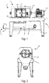
figure 1 shows a front view of the separating machine, object of the present invention; -
figure 2 shows a side view of the separating machine; -
figure 3 shows a perspective view of the separating machine; and -
figure 4 shows a perspective view of a component of the separating machine. - In the various figures, similar parts will be indicated with the same numerical references.
- With reference to
figures 1-3 , the separating machine M for processing material, object of the present invention, in particular for the separation of heterogeneous material in the components that compose it, comprises asupport frame 1, aseparating device 2, arranged on saidsupport frame 1, containing the waste material, made of pits and pomace, a first collection member 3, connected to said separatingdevice 2, capable of collecting the pomace, asecond collection member 4, connected to said separatingdevice 2, capable of collecting the pits, and ascraping device 5 coupled to said separatingdevice 2. - Said
support frame 1 comprises ahorizontal surface 11 capable of supporting components that are coupled to it, and one or morevertical components 12, coupled to saidhorizontal surface 11 and which allow the grounding of said machine M. - On said
horizontal surface 11 is obtained an opening, not shown in the figure, capable of putting said separatingdevice 2 in communication with said first collection member 3 andsecond collection member 4. - Said separating
device 2 comprises an externalprotective casing 21, aseparator member 22 arranged inside saidprotective casing 21, afirst motor 23 and arotor 24 connected to saidfirst motor 23 and able to rotate internally to saidseparator member 22. - Said
protective casing 21 surrounds saidseparator member 22 and it is capable of protecting saidseparator member 22 from the external environment and vice versa and is arranged in correspondence with said opening of saidhorizontal surface 11. - With particular reference to
figure 3 , saidprotective casing 21 has aninlet duct 211 for the waste material connected to saidseparator member 22, through which said waste material is conveyed into saidseparator member 22. - Referring now to
figure 4 , saidseparator member 22 comprises a hollow piercedsurface 221, which extends along a development axis X, from afirst end 222 to a secondopen end 223. - Said pierced
surface 221 comprises anexternal side 221a. - The non-separated waste material is arranged inside said pierced
surface 221. - Furthermore, said
second end 223 is open and is capable of making said pits come out. - With reference to
figures 1-3 , saidfirst motor 23 is fixed to saidhorizontal surface 11. - Said
first motor 23 comprises aflange 231, able to be coupled to saidrotor 24. - Said
rotor 24 is positioned inside saidseparator member 22 and is able to rotate inside saidseparator member 22 to move said waste material. - Said first collection member 3 is arranged below said
horizontal surface 11, in correspondence with said opening. - Said first collection member 3 comprises a
hopper 31 and afirst duct 32, inside which a screw conveyor for transporting the pomace towards the outlet is arranged, connected to saidseparator member 22 by means of saidhopper 31. - In particular, said
hopper 31 is placed in correspondence with said opening and is able to collect the pomace that falls from saidseparator member 22 and convey it towards saidfirst duct 32. - Said
first duct 32 is able to let the pomace come out towards the outside of said machine M. - Said
second collection member 4 comprises asecond duct 41, within which a screw for transporting the pits is arranged, and anoutlet portion 42 for the pits. - Said
outlet portion 42 is connected to saidseparator member 22 by means of saidsecond duct 41. - Said
second duct 41 is capable of collecting the separate pits coming out of saidseparator member 22 and conveying them towards saidoutlet portion 42, which is able to make the pits to come out towards the outside of said machine M. - Referring to
figure 4 , saidscraping device 5 is coupled to saidseparator member 22 and is capable of scraping said piercedsurface 221, in particular, saidexternal side 221a, of saidseparator member 22, and removing the pomace deposited on saidexternal side 221a of said piercedsurface 221. - Said
scraping device 5 comprises atransmission group 51, one or morescraping members 52, and one ormore guides 53. - Said one or more scraping
members 52 are moved by saidtransmission group 51 and coupled to said one ormore guides 53. - Said
transmission group 51 comprises asecond motor 511, agearbox 512, ashaft 513, and adirectional member 514. - Said
shaft 513 is able to rotate around its own axis, parallel to said development axis X, and comprises aguide groove 513a, capable of moving a member connected to it. - In particular, said
guide groove 513a is a double-principle helical groove, which therefore allows a member connected to it to be moved along the axis of saidshaft 513 in reciprocating motion, without having to reverse the rotation direction of saidshaft 513. - Said
directional member 514 comprises apin 514a and anaxial element 514b. - Said
directional member 514 is coupled to saidshaft 513 by means of saidpin 514a, which is capable of sliding along saidguide groove 513a. - Said
axial element 514b is capable of moving along said development axis X, in a manner integral with the movement along, said development axis X of said pin 514a. - Said
second motor 511 is coupled to saidshaft 513 by means of saidgearbox 512 and is capable of moving saidshaft 513. - Said one or
more scraping members 52 comprise one ormore flanges 521 and one ormore scraping elements - Said one or
more flanges 521 are coupled to said one ormore guides 53 and to saiddirectional member 514. - Said
directional member 514 is able to axially move said one ormore flanges 521. - Said one or
more flanges 521 are able to axially slide along said one ormore guides 53 when moved by saiddirectional member 514, along said development axis X. - Said one or
more scraping elements more flanges 521 and are able to scrape saidexternal side 221a of said piercedsurface 221 of saidseparator member 22. - In this embodiment, said one or
more scraping elements first scraping element 522a and asecond scraping element 522b. - Without departing from the scope of protection of the present invention, it is possible that said one or
more scraping elements - In this embodiment, said scraping
elements 522 are in particular made of polypropylene, so as to minimize the friction between said one ormore scraping elements external side 221a of said piercedsurface 221 of saidmember separator 22. - Without departing from the scope of protection of the present invention, it is possible that said one or
more scraping elements 522 are made of other materials, such as AISI 304. - The operation of the machine M for processing material, object of the present invention described above is as follows.
- When it is intended to separate the waste materials produced by the oil extraction from the olives, that is the pomace and the pits, said waste materials are introduced into said
separator member 22 through saidinlet duct 211. - The separation begins by starting said
first engine 23, which rotates saidrotor 24 inside saidseparator member 22. - The
rotor 24 moves the waste materials inside saidseparator member 22, which moves towards said piercedsurface 221 due to the centrifugal force. - The holes of said pierced
surface 221 are sufficiently large to allow the pomace to flow towards the outside of saidseparator member 22, but sufficiently small to retain the pits inside. - The pits are then retained inside said
separator member 22, while the pomace exits from saidseparator member 22 through the holes. - The pits then run through the interior of said
separator member 22 said along the development axis X, until they exit through saidsecond end 223 and enter saidsecond duct 41 by gravity. - The pits are then conveyed towards said
outlet portion 42. - The pits coming out of said
outlet portion 42 can finally be collected using an external container. - Due to its high viscosity, the pomace coming out of said
separator member 22 through the holes tends to deposit on saidexternal side 221a side of said piercedsurface 221. - The deposit of the pomace partially or completely obstructs the holes of said pierced
surface 221, and it, therefore, makes it difficult to release further pomace. - To avoid said deposit, said
scraping device 5 is operated. - In particular, said
second motor 511 is operated and saidshaft 513 is consequently moved by means of saidgearbox 512. - Said
directional member 514 is then moved along said development axis X through saidguide 513a. - In particular, said
pin 514a moves along saidguide groove 513a, causing saiddirectional member 514 to perform an alternating axial rectilinear motion. - Said one or
more scraping members 52, therefore, move axially in a manner integral with saiddirectional member 514. - In particular, said one or
more scraping members 52 slide along said one ormore guides 53 according to said development axis X. - Even more particularly, said one or
more scraping elements 522 scrape saidexternal side 221a of said piercedsurface 221 of saidseparator member 22, by means of an alternating axial movement. - This allows to completely scrape said
external side 221a of said piercedsurface 221 of saidseparator member 22, and therefore to remove all the residue deposited. - The complete removal of the pomace from said
external side 221a of said piercedsurface 221 facilitates the release of further pomace from saidseparator member 22. - This allows for optimizing the separation process of pomace and pits.
- Once scraped from said
external side 221a of said piercedsurface 221 of saidseparator member 22, the pomace falls into saidhopper 31. - Said
hopper 31 then conveys the pomace towards saidfirst duct 32. - The pomace coming out of said
first duct 32 can finally be collected through an external container. - A first advantage of the separating machine M for processing material, object of the present invention, described above, is the possibility of having a device capable of scraping and removing the pomace from all of said
external side 221a of said piercedsurface 221. - This is possible by the alternating axial movement along said development axis X of said
scraping device 5. - A further advantage of the separating machine M for processing material, object of the present invention, is the possibility of making the separation process more efficient than the machines of prior art.
- In fact, the removal of the pomace from said
external side 221a of said piercedsurface 221 allows the exit of further pomace from saidseparator member 22, maximizing the efficiency of the separation. - The present invention has been described for illustrative but not limitative purposes, according to its preferred embodiments, but it is to be understood that modifications and/or changes can be introduced by those skilled in the art without departing from the relevant scope as defined in the enclosed claims.
Claims (8)
- Separating machine (M) for the processing of heterogeneous material comprisinga separating device (2), provided with a pierced surface (221) which develops along a development axis (X), capable of containing a heterogeneous material and capable of causing the separation of said heterogeneous material in a first component and a second component and the pouring of said first component through said pierced surface (221),said machine being characterized in that it comprises a scraping device (5), slidably coupled to and in contact with said pierced surface (221) of said separating device (2), capable of moving along a direction parallel to said development axis (X), to remove said first component from said pierced surface (221).
- Machine (M) according to the previous claim, characterized in that said scraping device (5) moves in alternate motion along said development axis (X).
- Machine (M) according to the previous claim, characterized in that said scraping device (5) comprises a transmission group (51) and one or more scraping members (52).
- Machine (M) according to the previous claim, characterized in that said one or more scraping members (52) are capable of translating along said development axis (X) via one or more guides (63).
- Machine (M) according to any of the claims 3-4, characterized in that said scraping members (52) comprisea first scraping element (522a) and a first flange (521a) fixed to it,a second scraping element (522b) and a second flange (521b) fixed to it,said first scraping element (522a) and second scraping element (522b) being integral with each other.
- Machine (M) according to the previous claim, characterized in that said first (522a) and second (522b) scraping elements are made of polypropylene.
- Machine (M) according to any of the claims 3-6, characterized in that said transmission group (51) comprises a motor (511), a gearbox (512), a directional member (514), comprising in turn a pin (514a) and a shaft (513), on which is obtained a double-start thread guide groove (513a), on which said directional member (514) is capable of moving via said pin (514a).
- Machine (M) according to any of the previous claims, characterizedin that it comprises a supporting frame (1), capable of supporting said separating device (2), comprising a horizontal surface (11) on which an opening is obtained,a first collection member (3), placed near said opening, capable of collecting the pomace coming out from said separating device (2),a second collection member (4), placed near said opening, capable of collecting the kernels coming out from said separating device (2).
Applications Claiming Priority (1)
| Application Number | Priority Date | Filing Date | Title |
|---|---|---|---|
| IT102021000013064A IT202100013064A1 (en) | 2021-05-20 | 2021-05-20 | Separating machine for processing material. |
Publications (3)
| Publication Number | Publication Date |
|---|---|
| EP4091459A1 true EP4091459A1 (en) | 2022-11-23 |
| EP4091459B1 EP4091459B1 (en) | 2026-02-18 |
| EP4091459C0 EP4091459C0 (en) | 2026-02-18 |
Family
ID=77519509
Family Applications (1)
| Application Number | Title | Priority Date | Filing Date |
|---|---|---|---|
| EP22172348.9A Active EP4091459B1 (en) | 2021-05-20 | 2022-05-09 | Separating machine for the processing of material |
Country Status (2)
| Country | Link |
|---|---|
| EP (1) | EP4091459B1 (en) |
| IT (1) | IT202100013064A1 (en) |
Cited By (1)
| Publication number | Priority date | Publication date | Assignee | Title |
|---|---|---|---|---|
| IT202300024216A1 (en) * | 2023-11-15 | 2025-05-15 | Mecc Spadoni S R L | MACHINERY AND METHOD FOR THE PRODUCTION OF OLIVE PASTE WITH AUTOMATIC WASHING |
Citations (5)
| Publication number | Priority date | Publication date | Assignee | Title |
|---|---|---|---|---|
| ES2051208A2 (en) * | 1992-02-14 | 1994-06-01 | Corcomi S L | Machine for washing/cleaning olives |
| ES2315147A1 (en) * | 2004-02-25 | 2009-03-16 | Ashlock Company | PROCEDURE AND APPARATUS FOR BONING AND CUTTING OLIVE ROLLS WITH A SET OF CUTTING KNIVES THAT CAN BE ADJUSTED LOADED WITH SPRING. |
| EP2721130B1 (en) * | 2011-06-15 | 2014-09-03 | Pieralisi Maip Societa' Per Azioni | Installation and method for extraction of oil from olive paste |
| JP2017088309A (en) * | 2015-11-09 | 2017-05-25 | 大同特殊鋼株式会社 | Conveyance device |
| CN109433581A (en) * | 2018-12-14 | 2019-03-08 | 爱可道生物科技有限公司 | A kind of adjustable globe artichoke size fractionation device for avoiding petal from damaging |
-
2021
- 2021-05-20 IT IT102021000013064A patent/IT202100013064A1/en unknown
-
2022
- 2022-05-09 EP EP22172348.9A patent/EP4091459B1/en active Active
Patent Citations (5)
| Publication number | Priority date | Publication date | Assignee | Title |
|---|---|---|---|---|
| ES2051208A2 (en) * | 1992-02-14 | 1994-06-01 | Corcomi S L | Machine for washing/cleaning olives |
| ES2315147A1 (en) * | 2004-02-25 | 2009-03-16 | Ashlock Company | PROCEDURE AND APPARATUS FOR BONING AND CUTTING OLIVE ROLLS WITH A SET OF CUTTING KNIVES THAT CAN BE ADJUSTED LOADED WITH SPRING. |
| EP2721130B1 (en) * | 2011-06-15 | 2014-09-03 | Pieralisi Maip Societa' Per Azioni | Installation and method for extraction of oil from olive paste |
| JP2017088309A (en) * | 2015-11-09 | 2017-05-25 | 大同特殊鋼株式会社 | Conveyance device |
| CN109433581A (en) * | 2018-12-14 | 2019-03-08 | 爱可道生物科技有限公司 | A kind of adjustable globe artichoke size fractionation device for avoiding petal from damaging |
Cited By (1)
| Publication number | Priority date | Publication date | Assignee | Title |
|---|---|---|---|---|
| IT202300024216A1 (en) * | 2023-11-15 | 2025-05-15 | Mecc Spadoni S R L | MACHINERY AND METHOD FOR THE PRODUCTION OF OLIVE PASTE WITH AUTOMATIC WASHING |
Also Published As
| Publication number | Publication date |
|---|---|
| IT202100013064A1 (en) | 2022-11-20 |
| EP4091459B1 (en) | 2026-02-18 |
| EP4091459C0 (en) | 2026-02-18 |
Similar Documents
| Publication | Publication Date | Title |
|---|---|---|
| FI83684C (en) | Apparatus for separating chisel material and / or sieved material from a liquid flowing into a drain | |
| EP1372863B1 (en) | Automatic solids discharge tubular bowl centrifuge | |
| EP0454045A2 (en) | Centrifugal drier | |
| CN111362447B (en) | Chemical sewage solid-liquid separator | |
| WO2014038518A1 (en) | Mixed liquid separation apparatus | |
| EP0056511A2 (en) | Improved centrifuge and method of cleaning a centrifuge drum | |
| EP4091459B1 (en) | Separating machine for the processing of material | |
| CN109967345A (en) | A kind of combined type cottonseed exclusion device | |
| CN117771802B (en) | A solid-liquid separation centrifuge for wastewater treatment and its usage method | |
| CN114042856A (en) | An online degreasing machine for fastener production | |
| CN116809200A (en) | Broken preparation facilities of matrimony vine extract product | |
| CN211386178U (en) | Biax takes off mark machine | |
| CN108620423A (en) | A kind of sorting kitchen waste device | |
| CN119549397B (en) | Feed pretreatment device with screening function for aquaculture and pretreatment process | |
| CN120588003A (en) | An automatic waste chip collection device for CNC machining centers | |
| CN210786444U (en) | Agricultural solid-liquid separator | |
| EP0050012B1 (en) | Process and apparatus for the continuous extraction of oils and soluble substances from solid materials | |
| CN112623554A (en) | Kitchen garbage cleaning device for central kitchen | |
| US2354096A (en) | Means for shelling eggs | |
| Sutherland | Centrifuge focus: solids removal–the options | |
| JP2001277113A (en) | Grinding fluid grinding stone grain removal method and device | |
| CN105413885A (en) | Centrifuge for automatically separating pulp and dregs | |
| CH362652A (en) | Centrifuge for separating dirt and residues from oil and other liquids with automatic emptying of the waste product | |
| KR102964745B1 (en) | Food waste separation and disposal device | |
| CN113028748B (en) | A have a screw conveyer for environmental protection machinery |
Legal Events
| Date | Code | Title | Description |
|---|---|---|---|
| PUAI | Public reference made under article 153(3) epc to a published international application that has entered the european phase |
Free format text: ORIGINAL CODE: 0009012 |
|
| STAA | Information on the status of an ep patent application or granted ep patent |
Free format text: STATUS: THE APPLICATION HAS BEEN PUBLISHED |
|
| AK | Designated contracting states |
Kind code of ref document: A1 Designated state(s): AL AT BE BG CH CY CZ DE DK EE ES FI FR GB GR HR HU IE IS IT LI LT LU LV MC MK MT NL NO PL PT RO RS SE SI SK SM TR |
|
| STAA | Information on the status of an ep patent application or granted ep patent |
Free format text: STATUS: REQUEST FOR EXAMINATION WAS MADE |
|
| P01 | Opt-out of the competence of the unified patent court (upc) registered |
Effective date: 20230502 |
|
| 17P | Request for examination filed |
Effective date: 20230523 |
|
| RBV | Designated contracting states (corrected) |
Designated state(s): AL AT BE BG CH CY CZ DE DK EE ES FI FR GB GR HR HU IE IS IT LI LT LU LV MC MK MT NL NO PL PT RO RS SE SI SK SM TR |
|
| GRAP | Despatch of communication of intention to grant a patent |
Free format text: ORIGINAL CODE: EPIDOSNIGR1 |
|
| STAA | Information on the status of an ep patent application or granted ep patent |
Free format text: STATUS: GRANT OF PATENT IS INTENDED |
|
| INTG | Intention to grant announced |
Effective date: 20251013 |
|
| GRAS | Grant fee paid |
Free format text: ORIGINAL CODE: EPIDOSNIGR3 |
|
| GRAA | (expected) grant |
Free format text: ORIGINAL CODE: 0009210 |
|
| STAA | Information on the status of an ep patent application or granted ep patent |
Free format text: STATUS: THE PATENT HAS BEEN GRANTED |
|
| AK | Designated contracting states |
Kind code of ref document: B1 Designated state(s): AL AT BE BG CH CY CZ DE DK EE ES FI FR GB GR HR HU IE IS IT LI LT LU LV MC MK MT NL NO PL PT RO RS SE SI SK SM TR |
|
| REG | Reference to a national code |
Ref country code: CH Ref legal event code: F10 Free format text: ST27 STATUS EVENT CODE: U-0-0-F10-F00 (AS PROVIDED BY THE NATIONAL OFFICE) Effective date: 20260218 Ref country code: GB Ref legal event code: FG4D |
|
| REG | Reference to a national code |
Ref country code: IE Ref legal event code: FG4D |
|
| REG | Reference to a national code |
Ref country code: DE Ref legal event code: R096 Ref document number: 602022030435 Country of ref document: DE |
|
| U01 | Request for unitary effect filed |
Effective date: 20260313 |
|
| U07 | Unitary effect registered |
Designated state(s): AT BE BG DE DK EE FI FR IT LT LU LV MT NL PT RO SE SI Effective date: 20260319 |
|
| P04 | Withdrawal of opt-out of the competence of the unified patent court (upc) registered |
Free format text: CASE NUMBER: UPC_APP_68951_1/2023 Effective date: 20260319 |
|
| U20 | Renewal fee for the european patent with unitary effect paid |
Year of fee payment: 5 Effective date: 20260319 |
|
| PG25 | Lapsed in a contracting state [announced via postgrant information from national office to epo] |
Ref country code: RS Free format text: LAPSE BECAUSE OF FAILURE TO SUBMIT A TRANSLATION OF THE DESCRIPTION OR TO PAY THE FEE WITHIN THE PRESCRIBED TIME-LIMIT Effective date: 20260518 |
|
| PG25 | Lapsed in a contracting state [announced via postgrant information from national office to epo] |
Ref country code: ES Free format text: LAPSE BECAUSE OF FAILURE TO SUBMIT A TRANSLATION OF THE DESCRIPTION OR TO PAY THE FEE WITHIN THE PRESCRIBED TIME-LIMIT Effective date: 20260218 |
|
| PG25 | Lapsed in a contracting state [announced via postgrant information from national office to epo] |
Ref country code: PL Free format text: LAPSE BECAUSE OF FAILURE TO SUBMIT A TRANSLATION OF THE DESCRIPTION OR TO PAY THE FEE WITHIN THE PRESCRIBED TIME-LIMIT Effective date: 20260218 |
|
| PG25 | Lapsed in a contracting state [announced via postgrant information from national office to epo] |
Ref country code: GR Free format text: LAPSE BECAUSE OF FAILURE TO SUBMIT A TRANSLATION OF THE DESCRIPTION OR TO PAY THE FEE WITHIN THE PRESCRIBED TIME-LIMIT Effective date: 20260519 |
|
| PG25 | Lapsed in a contracting state [announced via postgrant information from national office to epo] |
Ref country code: NO Free format text: LAPSE BECAUSE OF FAILURE TO SUBMIT A TRANSLATION OF THE DESCRIPTION OR TO PAY THE FEE WITHIN THE PRESCRIBED TIME-LIMIT Effective date: 20260518 |
|
| PG25 | Lapsed in a contracting state [announced via postgrant information from national office to epo] |
Ref country code: HR Free format text: LAPSE BECAUSE OF FAILURE TO SUBMIT A TRANSLATION OF THE DESCRIPTION OR TO PAY THE FEE WITHIN THE PRESCRIBED TIME-LIMIT Effective date: 20260218 |
|
| PG25 | Lapsed in a contracting state [announced via postgrant information from national office to epo] |
Ref country code: IS Free format text: LAPSE BECAUSE OF FAILURE TO SUBMIT A TRANSLATION OF THE DESCRIPTION OR TO PAY THE FEE WITHIN THE PRESCRIBED TIME-LIMIT Effective date: 20260618 |