EP4091432A1 - Siebinstallationsanordnung in einem reinigungssystem einer landwirtschaftlichen erntemaschine - Google Patents
Siebinstallationsanordnung in einem reinigungssystem einer landwirtschaftlichen erntemaschine Download PDFInfo
- Publication number
- EP4091432A1 EP4091432A1 EP21175440.3A EP21175440A EP4091432A1 EP 4091432 A1 EP4091432 A1 EP 4091432A1 EP 21175440 A EP21175440 A EP 21175440A EP 4091432 A1 EP4091432 A1 EP 4091432A1
- Authority
- EP
- European Patent Office
- Prior art keywords
- sieve
- bolts
- angled surface
- pair
- cleaning shoe
- Prior art date
- Legal status (The legal status is an assumption and is not a legal conclusion. Google has not performed a legal analysis and makes no representation as to the accuracy of the status listed.)
- Pending
Links
- 238000004140 cleaning Methods 0.000 title claims abstract description 69
- 238000009434 installation Methods 0.000 title 1
- 238000011144 upstream manufacturing Methods 0.000 claims abstract description 24
- 230000001154 acute effect Effects 0.000 claims abstract description 9
- 238000000034 method Methods 0.000 claims description 2
- 239000000463 material Substances 0.000 description 19
- 239000010902 straw Substances 0.000 description 7
- 239000000428 dust Substances 0.000 description 3
- 230000032258 transport Effects 0.000 description 3
- 239000013598 vector Substances 0.000 description 3
- 230000005484 gravity Effects 0.000 description 2
- 238000003306 harvesting Methods 0.000 description 2
- 230000033001 locomotion Effects 0.000 description 2
- 230000006978 adaptation Effects 0.000 description 1
- 230000005540 biological transmission Effects 0.000 description 1
- -1 chaff Substances 0.000 description 1
- 238000001125 extrusion Methods 0.000 description 1
- 238000005188 flotation Methods 0.000 description 1
- 239000012535 impurity Substances 0.000 description 1
- 239000002245 particle Substances 0.000 description 1
- 239000010908 plant waste Substances 0.000 description 1
Images


Classifications
-
- A—HUMAN NECESSITIES
- A01—AGRICULTURE; FORESTRY; ANIMAL HUSBANDRY; HUNTING; TRAPPING; FISHING
- A01D—HARVESTING; MOWING
- A01D41/00—Combines, i.e. harvesters or mowers combined with threshing devices
- A01D41/12—Details of combines
-
- A—HUMAN NECESSITIES
- A01—AGRICULTURE; FORESTRY; ANIMAL HUSBANDRY; HUNTING; TRAPPING; FISHING
- A01F—PROCESSING OF HARVESTED PRODUCE; HAY OR STRAW PRESSES; DEVICES FOR STORING AGRICULTURAL OR HORTICULTURAL PRODUCE
- A01F12/00—Parts or details of threshing apparatus
- A01F12/44—Grain cleaners; Grain separators
- A01F12/446—Sieving means
Definitions
- the present disclosure relates to a cleaning system used in an agricultural harvester, such as a combine, and, more particularly, to a sieve used in such a cleaning system.
- An agricultural harvester combines multiple harvesting functions with a single harvesting unit, such as picking, threshing, separating and cleaning.
- a combine includes a header which removes the crop from a field, and a feeder housing which transports the crop matter into a threshing rotor.
- the threshing rotor rotates within a perforated housing, which may be in the form of adjustable concaves, and performs a threshing operation on the crop to remove the grain.
- a perforated housing which may be in the form of adjustable concaves, and performs a threshing operation on the crop to remove the grain.
- the cleaning system includes a cleaning fan which blows air through oscillating sieves to discharge chaff and other debris toward the rear of the combine.
- Non-grain crop material such as straw from the threshing section proceeds through a straw chopper and out the rear of the combine.
- the combine When the grain tank becomes full, the combine is positioned adjacent a vehicle into which the grain is to be unloaded, such as a semi-trailer, gravity box, straight truck, or the like; and an unloading system on the combine is actuated to transfer the grain into the vehicle.
- a rotary threshing or separating system includes one or more rotors which can extend axially (front to rear) or transversely within the body of the combine, and which are partially or fully surrounded by a perforated concave.
- the crop material is threshed and separated by the rotation of the rotor within the concave.
- Coarser non-grain crop material such as stalks and leaves are transported to the rear of the combine and discharged back to the field.
- the separated grain, together with some finer non-grain crop material such as chaff, dust, straw, and other crop residue are discharged through the concaves and fall onto the grain pan where they are transported to the cleaning system.
- the grain and finer non-grain crop material may also fall directly onto the cleaning system itself.
- the cleaning system further separates the grain from non-grain crop material, and typically includes a fan directing an air flow stream upwardly and rearwardly through vertically arranged sieves which oscillate in a fore and aft manner.
- the air flow stream lifts and carries the lighter non-grain crop material towards the rear end of the combine for discharge to the field.
- Grain and non-grain crop material remaining on the upper and lower sieves are physically separated by the reciprocating action of the sieves as the material moves rearwardly. Any grain and/or non-grain crop material remaining on the top surface of the upper sieve are discharged at the rear of the combine. Grain falling through the lower sieve lands on a bottom pan of the cleaning system, where it is conveyed forwardly toward a clean grain auger.
- the clean grain auger is positioned below the lower sieve, and receives clean grain from each sieve and from the bottom pan of the cleaning system.
- the clean grain auger then augers the clean grain laterally sideways to a clean grain elevator, which in turn conveys the clean grain to a grain tank onboard the combine.
- a sieve assembly typically includes one or more sieves which are installed within a cleaning shoe that is oscillated in fore and aft motions to clean the grain while air flows through the sieve assembly.
- a sieve used in the sieve assembly typically includes a plurality of louvres extending cross-wise between the sides of the sieve, with the louvres including a plurality of fingers which are attached at their rear edge to respective wires. Depending on the crop being harvested, size of the kernels, amount of non-crop matter, etc, the louvre spacing (between the fingers) may need to be adjusted during operation.
- the present disclosure provides a sieve assembly with a sieve which is clamped against a cleaning shoe using a angled structure at the upstream end of the sieve and a pivoting bolt arrangement at the downstream end of the sieve.
- the disclosure in one form is directed to a sieve assembly for use in an agricultural harvester.
- the sieve assembly includes a cleaning shoe having a pair of opposed side rails, and a sieve which is removably installed within the cleaning shoe at a selected location against the side rails.
- the sieve has a downstream end and an upstream end, with the upstream end defining at least one first angled surface, and the downstream end defining at least one second angled surface.
- the cleaning shoe includes at least one first engagement surface for engaging the at least one first angled surface at the upstream end of the sieve.
- the cleaning shoe also includes a pair of bolts, with each of the bolts being pivotally attached relative to a respective one of the side rails and engageable with a respective second angled surface.
- Each of the bolts has a longitudinal axis that is positioned at an acute angle ( ⁇ ) relative to the side rails of the cleaning shoe and biases the at least one first angled surface into engagement with the at least one first engagement surface when the bolts are tightened against the respective second angled surface.
- each of the second angled surfaces comprises an arcuate surface.
- a pair of spherical washers are associated with each respective bolt and engageable with a respective arcuate surface.
- each of the spherical washers has a radius of curvature which mates with a radius of curvature of the arcuate surface.
- the sieve includes opposed side members.
- the at least one first angled surface comprises a pair of first angled surfaces respectively positioned at the upstream ends of the two side members.
- the at least one second angled surface comprises a pair of second angled surfaces respectively positioned at the downstream ends of the two side members.
- the pair of second angled surfaces each include a slot allowing a respective one of the bolts to be pivoted into place within the slot.
- a pair of first corner pieces respectively define the first angled surfaces
- a pair of second corner pieces respectively define the second angled surfaces
- each of the bolts comprises an eye bolt.
- a spherical washer, lock washer and nut are associated with each bolt.
- each of the bolts has an axis of rotation (R) which is positioned below a respective side rail of the cleaning shoe.
- the at least one first engagement surface comprises an angled surface defined by a bracket extending across the cleaning shoe between the side rails.
- downstream end and the upstream end are defined relative to a direction of air flow (F) through the sieve during operation.
- the acute angle ( ⁇ ) lies within a range of _ to _.
- the at least one first angled surface is positioned at an acute angle ( ⁇ ) relative to the side rails of the cleaning shoe.
- a method of installing a sieve within a cleaning system of an agricultural harvester uses the sieve of the present disclosure.
- FIG. 1 there is shown an agricultural harvester in the form of a combine 10, which generally includes a chassis 12, ground engaging wheels 14 and 16, header 18, feeder housing 20, operator cab 22, threshing and separating system 24, cleaning system 26, grain tank 28, and unloading auger 30.
- Front wheels 14 are larger flotation type wheels, and rear wheels 16 are smaller steerable wheels. Motive force is selectively applied to front wheels 14 through a power plant in the form of a diesel engine 32 and a transmission (not shown).
- combine 10 is shown as including wheels, is also to be understood that combine 10 may include tracks, such as full tracks or half tracks.
- Header 18 is mounted to the front of combine 10 and includes a cutter bar 34 for severing crops from a field during forward motion of combine 10.
- a rotatable reel 36 feeds the crop into header 18, and a double auger 38 feeds the severed crop laterally inwardly from each side toward feeder housing 20.
- Feeder housing 20 conveys the cut crop to threshing and separating system 24, and is selectively vertically movable using appropriate actuators, such as hydraulic cylinders (not shown).
- Threshing and separating system 24 is of the axial-flow type, and generally includes a rotor 40 at least partially enclosed by and rotatable within a corresponding perforated concave 42.
- the cut crops are threshed and separated by the rotation of rotor 40 within concave 42, and larger elements, such as stalks, leaves and the like are discharged from the rear of combine 10.
- Smaller elements of crop material including grain and non-grain crop material, including particles lighter than grain, such as chaff, dust and straw, are discharged through perforations of concave 42.
- Threshing and separating system 24 can also be a different type of system, such as a system with a transverse rotor rather than an axial rotor, etc.
- Cleaning system 26 may include an optional pre-cleaning sieve 46, an upper sieve 48 (also known as a chaffer sieve), a lower sieve 50 (also known as a cleaning sieve), and a cleaning fan 52.
- the upper sieve 48 and lower sieve 50 can be carried within a common framework, and are generally designated together as sieve 100, which will be described in more detail hereinafter.
- Grain on sieves 46, 48 and 50 is subjected to a cleaning action by fan 52 which provides an air flow through the sieves to remove chaff and other impurities such as dust from the grain by making this material airborne for discharge from straw hood 54 of combine 10.
- Grain pan 44 and pre-cleaning sieve 46 oscillate in a fore-to-aft manner to transport the grain and finer non-grain crop material to the upper surface of upper sieve 48.
- Upper sieve 48 and lower sieve 50 are vertically arranged relative to each other, and likewise oscillate in a fore-to-aft manner to spread the grain across sieves 48, 50, while permitting the passage of cleaned grain by gravity through the openings of sieves 48, 50.
- Clean grain falls to a clean grain auger 56 positioned crosswise below and toward the front of lower sieve 50.
- Clean grain auger 56 receives clean grain from each sieve 48, 50 and from bottom pan 58 of cleaning system 26.
- Clean grain auger 56 conveys the clean grain laterally to a generally vertically arranged grain elevator 60 for transport to grain tank 28.
- Tailings from cleaning system 26 fall to a tailings auger trough 62.
- the tailings are transported via tailings auger 64 and return auger 66 to the upstream end of cleaning system 26 for repeated cleaning action.
- a pair of grain tank augers 68 at the bottom of grain tank 28 convey the clean grain laterally within grain tank 28 to unloading auger 30 for discharge from combine 10.
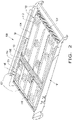
- the sieve assembly 100 includes a cleaning shoe 101 in which the upper sieve 48 and lower sieve 50 can be removably installed.
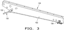
- the cleaning shoe 101 includes a pair of opposed and substantially identical side rails 103 (only one of which is visible in Fig. 3 ), upon which the lower sieve 50 can be mounted.
- the cleaning shoe 101 also includes another pair of side rails (not shown) located upstream from the side rail 103 visible in Fig. 3 , upon which the upper sieve 48 can be installed.
- the upper sieve 48 and lower sieve 50 are each clamped into the cleaning shoe 101 in such a way that the sieves 48, 50 are biased in both a rearward (upstream) direction and a downward direction against the side rails of the cleaning shoe 101.
- the upper sieve 48 and lower sieve 50 each generally include a framework 102 with a pair of opposed side members 104 (only one of which is visible for each sieve 48, 50 in Fig. 2 ).
- a first cross member 108 extends between the side members 104 at one end of the side members 104 and a second cross member 110 extends between the side members 104 at an opposite end of the side members 104.
- the first cross member 108 is positioned at the downstream end of the sieve 48 or 50
- the second cross member 110 is positioned at the upstream end of the sieve 48 or 50.
- each louvre 112 includes a plurality of fingers 114 which are attached at their rear ends to a corresponding wire 116.
- the wires 116 are pivotally mounted at opposite ends to the side members 104.
- the fingers 114 overlap relative to and can be offset from the fingers 114 of adjacent louvres.
- the spacing between the fingers 114 of adjacent louvres can be adjusted by simultaneously rotating the wires 116 within the side members 104.
- Fig. 4 is a redacted view only showing a couple of the louvres 112, for simplicity sake and ease of illustration.
- the lower sieve 50 can be clamped within the cleaning shoe 101.
- the upper sieve 48 can be similarly mounted within the cleaning shoe 101.
- the lower sieve 50 has a downstream end 118 and an upstream end 120 relative to a direction of air flow F through the lower sieve 50 during operation.
- the upstream end 120 defines at least one first angled surface 122 which is positioned at an acute angle ⁇ relative to the side rails 103 of the cleaning shoe 101.
- the angle ⁇ can be any desired angle allowing a wedged fit of the sieves 48, 50 with the cleaning shoe 101.
- the first angled surface 122 can be parallel to the side rail 103, such that the angle ⁇ has a value at or near zero (0) relative to the side rails 103.
- the at least one first angled surface 122 is configured as a pair of first angled surfaces 122 which are respectively positioned at the upstream ends 120 of the two side members 104. More particularly, a pair of first corner pieces 126 respectively define the pair of first angled surfaces 122. Similarly, a pair of second angled surfaces 124 can be respectively positioned at the downstream ends 118 of the two side members 104. In the illustrated embodiment, a pair of second corner pieces 128 respectively define the pair of second angled surfaces 124. Each of the second angled surfaces 124 has an arcuate surface with a radius of curvature R. The specific value of the radius of curvature R can vary, as will be described below.
- the first and second angled surfaces 122, 124 are defined at the ends of the side members 104.
- the angled surfaces could be formed at a different part of the downstream end 118 or upstream end 120 of the side members 104.
- the upstream second cross member 110 can be configured as an extrusion with a wedge shape that extends across the entire width of the lower sieve 50.
- the cleaning shoe 101 includes at least one first engagement surface 130 ( Fig. 3 ) for engaging the at least one first angled surface 122 at the upstream end of the sieve 50.
- the at least one first engagement surface 130 is in the form of an angled surface defined by a bracket 132 extending across the width of the cleaning shoe 101 between the side rails 103.
- the angular orientation of the angled surface defined by the bracket 132 can be slightly less than the first angled surface 122, so as to exert a slight clamping force on the first angled surface 122.
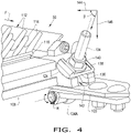
- the cleaning shoe 101 also includes a pair of bolts 134 which are pivotally attached relative to a respective one of the side rails 103 and engageable with a respective second angled surface 124.
- each of the bolts 134 is configured as an eye bolt with an axis of rotation R that is positioned below the corresponding side rail 103 of cleaning shoe 101.
- the eye 134A of the eye bolt 134 can be pivotally attached to the cleaning shoe 101 or side rail 103 by suitable structure, such as a bolt or pin (not numbered).
- Each of the bolts (134) has a longitudinal axis that is positioned at an acute angle ( ⁇ ) relative to the side rails (103) of the cleaning shoe (101) and biases the at least one first angled surface (122) into engagement with the at least one first engagement surface (130) when the bolts (134) are tightened against the respective second angled surface (124).
- a pair of spherical washers 136, lock washers 138 and nuts 140 are respectively associated with each bolt 134.
- the pair of spherical washers 136 are associated with each respective bolt 134 and engageable with an arcuate surface of a respective second angled surface 124.
- the spherical washers 136 define second engagement surfaces which directly contact the second angled surfaces 124.
- the pair of second angled surfaces 124 each include a slot 142 ( Fig. 6 ) allowing a respective one of the bolts 134 to be pivoted into place within the slot 142.
- Each of the spherical washers 136 has a radius of curvature which mates with a radius of curvature of the arcuate surface of a respective second angled surface 124.
- the radius of curvature of the spherical washer 13 can be configured to have an origin or starting point which lies along the axis of the bolt 134.
- the particular value of the radius of curvature of the spherical washers 136 can vary, depending on the application.
- the lock washers 138 can be a separate conventional split lock washer, or alternatively can be a toothed lock washer, or integrally incorporated with the nut 140 as a serrated fastener.
- the lock washers 138 function to hold the bolt 134 firmly in place at a selected angle ⁇ relative to the side rails 103.
- the clamping action of the bolt 134 at the angle ⁇ results in two force vectors 144, 146 applied to the second angled surface 124.
- the force vector 144 biases the lower sieve 50 in a direction toward the first engagement surface 130 at the upstream end of the lower sieve 50.
- the force vector 146 biases the lower sieve 50 in a downward direction toward the side rails 103 of the cleaning shoe 101.
- the angled clamping force applied by the bolts 134 results in secure and reliable clamping of the lower sieve 50 within the cleaning shoe 101.
Landscapes
- Life Sciences & Earth Sciences (AREA)
- Environmental Sciences (AREA)
- Threshing Machine Elements (AREA)
- Cleaning In General (AREA)
- Combined Means For Separation Of Solids (AREA)
Priority Applications (4)
| Application Number | Priority Date | Filing Date | Title |
|---|---|---|---|
| EP21175440.3A EP4091432A1 (de) | 2021-05-21 | 2021-05-21 | Siebinstallationsanordnung in einem reinigungssystem einer landwirtschaftlichen erntemaschine |
| BR102022009818-2A BR102022009818A2 (pt) | 2021-05-21 | 2022-05-19 | Conjunto de peneira para uso em uma colheitadeira agrícola e método de instalação de uma peneira de um sistema de limpeza em uma colheitadeira agrícola |
| US17/748,236 US20220369559A1 (en) | 2021-05-21 | 2022-05-19 | Sieve installation arrangement in a cleaning system of an agricultural harvester |
| CN202210558299.7A CN115380699A (zh) | 2021-05-21 | 2022-05-20 | 农业收割机的清洁系统中的筛安装布置 |
Applications Claiming Priority (1)
| Application Number | Priority Date | Filing Date | Title |
|---|---|---|---|
| EP21175440.3A EP4091432A1 (de) | 2021-05-21 | 2021-05-21 | Siebinstallationsanordnung in einem reinigungssystem einer landwirtschaftlichen erntemaschine |
Publications (1)
| Publication Number | Publication Date |
|---|---|
| EP4091432A1 true EP4091432A1 (de) | 2022-11-23 |
Family
ID=76076227
Family Applications (1)
| Application Number | Title | Priority Date | Filing Date |
|---|---|---|---|
| EP21175440.3A Pending EP4091432A1 (de) | 2021-05-21 | 2021-05-21 | Siebinstallationsanordnung in einem reinigungssystem einer landwirtschaftlichen erntemaschine |
Country Status (4)
| Country | Link |
|---|---|
| US (1) | US20220369559A1 (de) |
| EP (1) | EP4091432A1 (de) |
| CN (1) | CN115380699A (de) |
| BR (1) | BR102022009818A2 (de) |
Citations (4)
| Publication number | Priority date | Publication date | Assignee | Title |
|---|---|---|---|---|
| DE1082077B (de) * | 1959-05-04 | 1960-05-19 | Fahr Ag Maschf | Vorrichtung zum Befestigen von Dreschmaschinensieben |
| GB1075906A (en) * | 1966-03-02 | 1967-07-19 | Fortschritt Veb K | Sieve arrangements |
| US4770190A (en) * | 1987-05-15 | 1988-09-13 | Deere & Company | Cleaning shoe screen for an agricultural combine having readily replaceable louvers |
| US20090061968A1 (en) * | 2007-08-28 | 2009-03-05 | Claerhout Bryan S | Rear accessible sieve retainer |
Family Cites Families (7)
| Publication number | Priority date | Publication date | Assignee | Title |
|---|---|---|---|---|
| US4148724A (en) * | 1977-12-13 | 1979-04-10 | Hannon Electric Company | Wedge-type tensioning rail construction for electrically heated screens |
| US7175027B2 (en) * | 2002-01-23 | 2007-02-13 | Varco I/P, Inc. | Shaker screen and clamping system |
| US7371162B2 (en) * | 2006-04-24 | 2008-05-13 | Cnh America Llc | Sieve adjustment mechanism for an agricultural combine |
| CN104620781B (zh) * | 2015-03-16 | 2017-07-25 | 中联重机股份有限公司 | 一种联合收割机及其清选筛箱 |
| EP3120685B1 (de) * | 2015-07-23 | 2018-11-21 | CNH Industrial Belgium nv | Siebanordnungen für ein reinigungssystem in einer landwirtschaftlichen erntemaschine |
| US10212888B2 (en) * | 2017-02-08 | 2019-02-26 | Cnh Industrial America Llc | Sieve arrangement in a cleaning system for a combine harvester |
| US10959380B2 (en) * | 2019-03-12 | 2021-03-30 | Cnh Industrial America Llc | Sieve for an agricultural harvester with adjustable louvers and associated adjustment assembly |
-
2021
- 2021-05-21 EP EP21175440.3A patent/EP4091432A1/de active Pending
-
2022
- 2022-05-19 US US17/748,236 patent/US20220369559A1/en active Pending
- 2022-05-19 BR BR102022009818-2A patent/BR102022009818A2/pt unknown
- 2022-05-20 CN CN202210558299.7A patent/CN115380699A/zh active Pending
Patent Citations (4)
| Publication number | Priority date | Publication date | Assignee | Title |
|---|---|---|---|---|
| DE1082077B (de) * | 1959-05-04 | 1960-05-19 | Fahr Ag Maschf | Vorrichtung zum Befestigen von Dreschmaschinensieben |
| GB1075906A (en) * | 1966-03-02 | 1967-07-19 | Fortschritt Veb K | Sieve arrangements |
| US4770190A (en) * | 1987-05-15 | 1988-09-13 | Deere & Company | Cleaning shoe screen for an agricultural combine having readily replaceable louvers |
| US20090061968A1 (en) * | 2007-08-28 | 2009-03-05 | Claerhout Bryan S | Rear accessible sieve retainer |
Also Published As
| Publication number | Publication date |
|---|---|
| CN115380699A (zh) | 2022-11-25 |
| US20220369559A1 (en) | 2022-11-24 |
| BR102022009818A2 (pt) | 2022-12-06 |
Similar Documents
| Publication | Publication Date | Title |
|---|---|---|
| US11277969B2 (en) | Adjusting system for fingerstyle grates of an agricultural harvester | |
| EP3153009B1 (de) | Schlagleiste für einen mähdrescher | |
| EP3092891B1 (de) | Häcksler für eine landwirtschaftliche erntemaschine | |
| EP2996457B1 (de) | Abdeckplatte für eine reinkornschnecke in einem reinigungssystem einer landwirtschaftlichen erntemaschine | |
| US10959379B2 (en) | Adjustable vanes for use in a cylindrical rotor cage of an agricultural harvester | |
| US20220369561A1 (en) | Adjustment arrangement for offset spacing between louvres in a sieve of an agricultural harvester | |
| EP3245861B1 (de) | Drescheinrichtung mit zwei reihen von verstellbaren schaufeln für einen zylindrischen läuferkäfig einer landwirtschaftlichen erntemaschine und methode für die kontrolle der schaufeln | |
| US10058036B2 (en) | Structural members for a side shaking sieve arrangement in an agricultural harvester | |
| EP4091432A1 (de) | Siebinstallationsanordnung in einem reinigungssystem einer landwirtschaftlichen erntemaschine | |
| US10123486B2 (en) | Frame for agricultural harvester cleaner | |
| US20220369560A1 (en) | Sieve for an agricultural harvester including extruded sides with polymeric strips | |
| US20220369562A1 (en) | Adjustment arrangement for a sieve in an agricultural harvester | |
| US10091940B2 (en) | Straw walker arrangement for an agricultural harvester | |
| EP3479675B1 (de) | Rotorkäfig mit flachen wänden für ein landwirtschaftliches fahrzeug | |
| US20200296895A1 (en) | Removable insert for a threshing rotor cage |
Legal Events
| Date | Code | Title | Description |
|---|---|---|---|
| PUAI | Public reference made under article 153(3) epc to a published international application that has entered the european phase |
Free format text: ORIGINAL CODE: 0009012 |
|
| STAA | Information on the status of an ep patent application or granted ep patent |
Free format text: STATUS: THE APPLICATION HAS BEEN PUBLISHED |
|
| AK | Designated contracting states |
Kind code of ref document: A1 Designated state(s): AL AT BE BG CH CY CZ DE DK EE ES FI FR GB GR HR HU IE IS IT LI LT LU LV MC MK MT NL NO PL PT RO RS SE SI SK SM TR |
|
| STAA | Information on the status of an ep patent application or granted ep patent |
Free format text: STATUS: REQUEST FOR EXAMINATION WAS MADE |
|
| 17P | Request for examination filed |
Effective date: 20230523 |
|
| RBV | Designated contracting states (corrected) |
Designated state(s): AL AT BE BG CH CY CZ DE DK EE ES FI FR GB GR HR HU IE IS IT LI LT LU LV MC MK MT NL NO PL PT RO RS SE SI SK SM TR |
|
| P01 | Opt-out of the competence of the unified patent court (upc) registered |
Effective date: 20240320 |