EP4089970A2 - Procédé et appareil de mesure et de synchronisation de signal de référence - Google Patents
Procédé et appareil de mesure et de synchronisation de signal de référence Download PDFInfo
- Publication number
- EP4089970A2 EP4089970A2 EP22183015.1A EP22183015A EP4089970A2 EP 4089970 A2 EP4089970 A2 EP 4089970A2 EP 22183015 A EP22183015 A EP 22183015A EP 4089970 A2 EP4089970 A2 EP 4089970A2
- Authority
- EP
- European Patent Office
- Prior art keywords
- pbch
- sss
- pss
- bandwidth
- nrsss
- Prior art date
- Legal status (The legal status is an assumption and is not a legal conclusion. Google has not performed a legal analysis and makes no representation as to the accuracy of the status listed.)
- Pending
Links
Images


Classifications
-
- H—ELECTRICITY
- H04—ELECTRIC COMMUNICATION TECHNIQUE
- H04W—WIRELESS COMMUNICATION NETWORKS
- H04W56/00—Synchronisation arrangements
- H04W56/0005—Synchronisation arrangements synchronizing of arrival of multiple uplinks
-
- H—ELECTRICITY
- H04—ELECTRIC COMMUNICATION TECHNIQUE
- H04L—TRANSMISSION OF DIGITAL INFORMATION, e.g. TELEGRAPHIC COMMUNICATION
- H04L27/00—Modulated-carrier systems
- H04L27/26—Systems using multi-frequency codes
- H04L27/2601—Multicarrier modulation systems
- H04L27/2602—Signal structure
- H04L27/26025—Numerology, i.e. varying one or more of symbol duration, subcarrier spacing, Fourier transform size, sampling rate or down-clocking
-
- H—ELECTRICITY
- H04—ELECTRIC COMMUNICATION TECHNIQUE
- H04L—TRANSMISSION OF DIGITAL INFORMATION, e.g. TELEGRAPHIC COMMUNICATION
- H04L27/00—Modulated-carrier systems
- H04L27/26—Systems using multi-frequency codes
- H04L27/2601—Multicarrier modulation systems
- H04L27/2602—Signal structure
- H04L27/261—Details of reference signals
- H04L27/2613—Structure of the reference signals
-
- H—ELECTRICITY
- H04—ELECTRIC COMMUNICATION TECHNIQUE
- H04L—TRANSMISSION OF DIGITAL INFORMATION, e.g. TELEGRAPHIC COMMUNICATION
- H04L5/00—Arrangements affording multiple use of the transmission path
- H04L5/0001—Arrangements for dividing the transmission path
- H04L5/0014—Three-dimensional division
- H04L5/0023—Time-frequency-space
-
- H—ELECTRICITY
- H04—ELECTRIC COMMUNICATION TECHNIQUE
- H04L—TRANSMISSION OF DIGITAL INFORMATION, e.g. TELEGRAPHIC COMMUNICATION
- H04L5/00—Arrangements affording multiple use of the transmission path
- H04L5/003—Arrangements for allocating sub-channels of the transmission path
- H04L5/0032—Distributed allocation, i.e. involving a plurality of allocating devices, each making partial allocation
- H04L5/0035—Resource allocation in a cooperative multipoint environment
-
- H—ELECTRICITY
- H04—ELECTRIC COMMUNICATION TECHNIQUE
- H04L—TRANSMISSION OF DIGITAL INFORMATION, e.g. TELEGRAPHIC COMMUNICATION
- H04L5/00—Arrangements affording multiple use of the transmission path
- H04L5/003—Arrangements for allocating sub-channels of the transmission path
- H04L5/0048—Allocation of pilot signals, i.e. of signals known to the receiver
-
- H—ELECTRICITY
- H04—ELECTRIC COMMUNICATION TECHNIQUE
- H04L—TRANSMISSION OF DIGITAL INFORMATION, e.g. TELEGRAPHIC COMMUNICATION
- H04L5/00—Arrangements affording multiple use of the transmission path
- H04L5/003—Arrangements for allocating sub-channels of the transmission path
- H04L5/0053—Allocation of signaling, i.e. of overhead other than pilot signals
-
- H—ELECTRICITY
- H04—ELECTRIC COMMUNICATION TECHNIQUE
- H04L—TRANSMISSION OF DIGITAL INFORMATION, e.g. TELEGRAPHIC COMMUNICATION
- H04L5/00—Arrangements affording multiple use of the transmission path
- H04L5/003—Arrangements for allocating sub-channels of the transmission path
- H04L5/0058—Allocation criteria
- H04L5/0073—Allocation arrangements that take into account other cell interferences
-
- H—ELECTRICITY
- H04—ELECTRIC COMMUNICATION TECHNIQUE
- H04L—TRANSMISSION OF DIGITAL INFORMATION, e.g. TELEGRAPHIC COMMUNICATION
- H04L5/00—Arrangements affording multiple use of the transmission path
- H04L5/0091—Signaling for the administration of the divided path
- H04L5/0094—Indication of how sub-channels of the path are allocated
-
- H—ELECTRICITY
- H04—ELECTRIC COMMUNICATION TECHNIQUE
- H04J—MULTIPLEX COMMUNICATION
- H04J11/00—Orthogonal multiplex systems, e.g. using WALSH codes
- H04J11/0069—Cell search, i.e. determining cell identity [cell-ID]
- H04J11/0073—Acquisition of primary synchronisation channel, e.g. detection of cell-ID within cell-ID group
-
- H—ELECTRICITY
- H04—ELECTRIC COMMUNICATION TECHNIQUE
- H04J—MULTIPLEX COMMUNICATION
- H04J11/00—Orthogonal multiplex systems, e.g. using WALSH codes
- H04J11/0069—Cell search, i.e. determining cell identity [cell-ID]
- H04J11/0076—Acquisition of secondary synchronisation channel, e.g. detection of cell-ID group
Definitions
- the present disclosure relates generally to methods for measurement reference signals and synchronization signals. Such methods can be used when a user equipment attempts to initiate initial access, perform neighboring cell search, or radio resource management.
- the 5G or pre-5G communication system is also called a 'Beyond 4G Network' or a 'Post LTE System' .
- the 5G communication system is considered to be implemented in higher frequency (mmWave) bands, e.g., 28GHz or 60GHz bands, so as to accomplish higher data rates.
- mmWave e.g., 28GHz or 60GHz bands
- MIMO massive multiple-input multiple-output
- FD-MIMO Full Dimensional MIMO
- array antenna an analog beam forming, large scale antenna techniques are discussed in 5G communication systems.
- RANs Cloud Radio Access Networks
- D2D device-to-device
- wireless backhaul moving network
- cooperative communication Coordinated Multi-Points (CoMP), reception-end interference cancellation and the like.
- CoMP Coordinated Multi-Points
- FQAM Hybrid FSK and QAM Modulation
- SWSC sliding window superposition coding
- ACM advanced coding modulation
- FBMC filter bank multi carrier
- NOMA non-orthogonal multiple access
- SCMA sparse code multiple access
- Wireless communication has been one of the most successful innovations in modern history.
- the demand of wireless data traffic is rapidly increasing due to the growing popularity among consumers and businesses of smart phones and other mobile data devices, such as tablets, "note pad” computers, net books, eBook readers, and machine type of devices.
- improvements in radio interface efficiency and coverage is of paramount importance.
- a mobile device or user equipment can measure the quality of the downlink channel and report this quality to a base station so that a determination can be made regarding whether or not various parameters should be adjusted during communication with the mobile device.
- Existing channel quality reporting processes in wireless communications systems do not sufficiently accommodate reporting of channel state information associated with large, two dimensional array transmit antennas or, in general, antenna array geometry that accommodates a large number of antenna elements.
- Various embodiments of the present disclosure provide methods and apparatuses for CSI reporting.
- a user equipment includes a transceiver and a processor operably connected to the transceiver.
- the transceiver is configured to receive a primary synchronization signal (PSS), a secondary synchronization signal (SSS), and a primary broadcast channel (PBCH).
- the processor is configured to decode cell identification information from at least the PSS and the SSS and to decode a master information block (MIB) from the PBCH.
- PSS, the SSS, and the PBCH are time-division multiplexed. A same set of sequences are used for the PSS and the SSS for different carrier frequencies and different sub-carrier spacing values
- a base station in another embodiment, includes a processor and a transceiver operably connected to the processor.
- the processor is configured to encode cell identification information in at least a PSS and a SSS and encode a MIB in a PBCH.
- the transceiver is configured to transmit the PSS, the SSS, and the PBCH.
- the PSS, the SSS, and the PBCH are time-division multiplexed. A same set of sequences are used for the PSS and the SSS for different carrier frequencies and different sub-carrier spacing values.
- a method for operating a UE includes receiving, by the UE, a PSS, a SSS, and a PBCH. The method also includes decoding cell identification information from at least the PSS and the SSS and decoding a MIB from the PBCH.
- the PSS, the SSS, and the PBCH are time-division multiplexed. A same set of sequences are used for the PSS and the SSS for different carrier frequencies and different sub-carrier spacing values.
- the present disclosure relates to a pre-5th-Generation (5G) or 5G communication system to be provided for supporting higher data rates Beyond 4th-Generation (4G) communication system such as Long Term Evolution (LTE).
- 5G pre-5th-Generation
- 4G 4th-Generation
- LTE Long Term Evolution
- Couple and its derivatives refer to any direct or indirect communication between two or more elements, whether or not those elements are in physical contact with one another.
- transmit and “communicate,” as well as derivatives thereof, encompass both direct and indirect communication.
- the term “or” is inclusive, meaning and/or.
- controller means any device, system or part thereof that controls at least one operation. Such a controller can be implemented in hardware or a combination of hardware and software and/or firmware. The functionality associated with any particular controller can be centralized or distributed, whether locally or remotely.
- phrases "at least one of,” when used with a list of items, means that different combinations of one or more of the listed items can be used, and only one item in the list can be needed.
- “at least one of: A, B, and C” includes any of the following combinations: A, B, C, A and B, A and C, B and C, and A and B and C.
- various functions described below can be implemented or supported by one or more computer programs, each of that is formed from computer readable program code and embodied in a computer readable medium.
- application and “program” refer to one or more computer programs, software components, sets of instructions, procedures, functions, objects, classes, instances, related data, or a portion thereof adapted for implementation in a suitable computer readable program code.
- computer readable program code includes any type of computer code, including source code, object code, and executable code.
- computer readable medium includes any type of medium capable of being accessed by a computer, such as read only memory (ROM), random access memory (RAM), a hard disk drive, a compact disc (CD), a digital video disc (DVD), or any other type of memory.
- ROM read only memory
- RAM random access memory
- CD compact disc
- DVD digital video disc
- a "non-transitory” computer readable medium excludes wired, wireless, optical, or other communication links that transport transitory electrical or other signals.
- a non-transitory computer readable medium includes media where data can be permanently stored and media where data can be stored and later overwritten, such as a rewritable optical disc or an erasable memory device.
- FIGURES 1 through 11 discussed below, and the various embodiments used to describe the principles of the present disclosure in this patent document are by way of illustration only and should not be construed in any way to limit the scope of the disclosure. Those skilled in the art will understand that the principles of the present disclosure can be implemented in any suitably arranged wireless communication system.
- FIGURE 1 illustrates an example wireless network 100 according to various embodiments of the present disclosure.
- the embodiment of the wireless network 100 shown in FIGURE 1 is for illustration only. Other embodiments of the wireless network 100 could be used without departing from the scope of the present disclosure.
- the wireless network 100 includes a base station (BS) 101, a BS 102, and a BS 103.
- the BS 101 communicates with the BS 102 and the BS 103.
- the BS 101 also communicates with at least one Internet Protocol (IP) network 130, such as the Internet, a proprietary IP network, or other data network.
- IP Internet Protocol
- eNB enhanced Node B
- gNB general Node B
- gNB base station
- access point a point that provides wireless access to remote terminals.
- gNB and BS are used in this patent document to refer to network infrastructure components that provide wireless access to remote terminals.
- UE user equipment
- mobile station such as a mobile telephone or smartphone
- remote terminal such as a desktop computer or vending machine
- the gNB 102 provides wireless broadband access to the network 130 for a first plurality of user equipments (UEs) within a coverage area 120 of the gNB 102.
- the first plurality of UEs includes a UE 111, that can be located in a small business (SB); a UE 112, that can be located in an enterprise (E); a UE 113, that can be located in a WiFi hotspot (HS); a UE 114, that can be located in a first residence (R); a UE 115, that can be located in a second residence (R); and a UE 116, that can be a mobile device (M) like a cell phone, a wireless laptop, a wireless PDA, or the like.
- M mobile device
- the gNB 103 provides wireless broadband access to the network 130 for a second plurality of UEs within a coverage area 125 of the gNB 103.
- the second plurality of UEs includes the UE 115 and the UE 116.
- one or more of the gNBs 101-103 can communicate with each other and with the UEs 111-116 using 5G, LTE, LTE-A, WiMAX, or other advanced wireless communication techniques.
- Dotted lines show the approximate extents of the coverage areas 120 and 125, that are shown as approximately circular for the purposes of illustration and explanation only. It should be clearly understood that the coverage areas associated with gNBs, such as the coverage areas 120 and 125, can have other shapes, including irregular shapes, depending upon the configuration of the gNBs and variations in the radio environment associated with natural and man-made obstructions.
- one or more of gNB 101, gNB 102, and gNB 103 transmit measurement reference signals to UEs 111-116 and configure UEs 111-116 for CSI reporting as described in embodiments of the present disclosure.
- one or more of UEs 111-116 receive transmission scheme or precoding information signaled in an uplink grant and transmit accordingly.
- FIGURE 1 illustrates one example of a wireless network 100
- the wireless network 100 could include any number of gNBs and any number of UEs in any suitable arrangement.
- the gNB 101 could communicate directly with any number of UEs and provide those UEs with wireless broadband access to the network 130.
- each gNB 102-103 could communicate directly with the network 130 and provide UEs with direct wireless broadband access to the network 130.
- the gNB 101, 102, and/or 103 could provide access to other or additional external networks, such as external telephone networks or other types of data networks.
- FIGURES 2A and 2B illustrate example wireless transmit and receive paths according to the present disclosure.
- a transmit path 200 can be described as being implemented in a gNB (such as gNB 102), while a receive path 250 can be described as being implemented in a UE (such as UE 116).
- the receive path 250 could be implemented in a gNB and that the transmit path 200 could be implemented in a UE.
- the receive path 250 is configured to receive at least one measurement reference signal (RS) and at least one synchronization signal (SS) accordingly as described in embodiments of the present disclosure.
- RS measurement reference signal
- SS synchronization signal
- the transmit path 200 includes a channel coding and modulation block 205, a serial-to-parallel (S-to-P) block 210, a size N Inverse Fast Fourier Transform (IFFT) block 215, a parallel-to-serial (P-to-S) block 220, an add cyclic prefix block 225, and an up-converter (UC) 230.
- S-to-P serial-to-parallel
- IFFT Inverse Fast Fourier Transform
- P-to-S parallel-to-serial
- UC up-converter
- the receive path 250 includes a down-converter (DC) 255, a remove cyclic prefix block 260, a serial-to-parallel (S-to-P) block 265, a size N Fast Fourier Transform (FFT) block 270, a parallel-to-serial (P-to-S) block 275, and a channel decoding and demodulation block 280.
- DC down-converter
- S-to-P serial-to-parallel
- FFT Fast Fourier Transform
- P-to-S parallel-to-serial
- the channel coding and modulation block 205 receives a set of information bits, applies coding (such as convolutional, Turbo, or low-density parity check (LDPC) coding), and modulates the input bits (such as with Quadrature Phase Shift Keying (QPSK) or Quadrature Amplitude Modulation (QAM)) to generate a sequence of frequency-domain modulation symbols.
- the serial-to-parallel block 210 converts (such as de-multiplexes) the serial modulated symbols to parallel data in order to generate N parallel symbol streams, where N is the IFFT/FFT size used in the gNB 102 and the UE 116.
- the size N IFFT block 215 performs an IFFT operation on the N parallel symbol streams to generate time-domain output signals.
- the parallel-to-serial block 220 converts (such as multiplexes) the parallel time-domain output symbols from the size N IFFT block 215 in order to generate a serial time-domain signal.
- the 'add cyclic prefix' block 225 inserts a cyclic prefix to the time-domain signal.
- the up-converter 230 modulates (such as up-converts) the output of the 'add cyclic prefix' block 225 to an RF frequency for transmission via a wireless channel.
- the signal can also be filtered at baseband before conversion to the RF frequency.
- a transmitted RF signal from the gNB 102 arrives at the UE 116 after passing through the wireless channel, and reverse operations to those at the gNB 102 are performed at the UE 116.
- the down-converter 255 down-converts the received signal to a baseband frequency
- the remove cyclic prefix block 260 removes the cyclic prefix to generate a serial time-domain baseband signal.
- the serial-to-parallel block 265 converts the time-domain baseband signal to parallel time domain signals.
- the size N FFT block 270 performs an FFT algorithm to generate N parallel frequency-domain signals.
- the parallel-to-serial block 275 converts the parallel frequency-domain signals to a sequence of modulated data symbols.
- the channel decoding and demodulation block 280 demodulates and decodes the modulated symbols to recover the original input data stream.
- the transmit path 200 or the receive path 250 can perform signaling for CSI reporting.
- Each of the gNBs 101-103 can implement a transmit path 200 that is analogous to transmitting in the downlink to UEs 111-116 and can implement a receive path 250 that is analogous to receiving in the uplink from UEs 111-116.
- each of UEs 111-116 can implement a transmit path 200 for transmitting in the uplink to gNBs 101-103 and can implement a receive path 250 for receiving in the downlink from gNBs 101-103.
- FIGURES 2A and 2B can be implemented using only hardware or using a combination of hardware and software/firmware.
- at least some of the components in FIGURES 2A and 2B can be implemented in software, while other components can be implemented by configurable hardware or a mixture of software and configurable hardware.
- the FFT block 270 and the IFFT block 215 can be implemented as configurable software algorithms, where the value of size N can be modified according to the implementation.
- variable N can be any integer number (such as 1, 2, 3, 4, or the like) for DFT and IDFT functions, while the value of the variable N can be any integer number that is a power of two (such as 1, 2, 4, 8, 16, or the like) for FFT and IFFT functions.
- FIGURES 2A and 2B illustrate examples of wireless transmit and receive paths
- various changes can be made to FIGURES 2A and 2B .
- various components in FIGURES 2A and 2B could be combined, further subdivided, or omitted and additional components could be added according to particular needs.
- FIGURES 2A and 2B are meant to illustrate examples of the types of transmit and receive paths that could be used in a wireless network.
- Other suitable architectures could be used to support wireless communications in a wireless network.
- FIGURE 3A illustrates an example UE 116 according to the present disclosure.
- the embodiment of the UE 116 illustrated in FIGURE 3A is for illustration only, and the UEs 111-115 of FIGURE 1 could have the same or similar configuration.
- UEs come in a wide variety of configurations, and FIGURE 3A does not limit the scope of the present disclosure to any particular implementation of a UE.
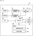
- the UE 116 includes an antenna 305, a radio frequency (RF) transceiver 310, transmit (TX) processing circuitry 315, a microphone 320, and receive (RX) processing circuitry 325.
- the UE 116 also includes a speaker 330, a processor 340, an input/output (I/O) interface (IF) 345, an input 350, a display 355, and a memory 360.
- the memory 360 includes an operating system (OS) program 361 and one or more applications 362.
- OS operating system
- the RF transceiver 310 receives, from the antenna 305, an incoming RF signal transmitted by a gNB of the network 100.
- the RF transceiver 310 down-converts the incoming RF signal to generate an intermediate frequency (IF) or baseband signal.
- the IF or baseband signal is sent to the RX processing circuitry 325, that generates a processed baseband signal by filtering, decoding, and/or digitizing the baseband or IF signal.
- the RX processing circuitry 325 transmits the processed baseband signal to the speaker 330 (such as for voice data) or to the processor 340 for further processing (such as for web browsing data).
- the TX processing circuitry 315 receives analog or digital voice data from the microphone 320 or other outgoing baseband data (such as web data, e-mail, or interactive video game data) from the processor 340.
- the TX processing circuitry 315 encodes, multiplexes, and/or digitizes the outgoing baseband data to generate a processed baseband or IF signal.
- the RF transceiver 310 receives the outgoing processed baseband or IF signal from the TX processing circuitry 315 and up-converts the baseband or IF signal to an RF signal that is transmitted via the antenna 305.
- the processor 340 can include one or more processors or other processing devices and execute the OS program 361 stored in the memory 360 in order to control the overall operation of the UE 116.
- processor 340 could control the reception of forward channel signals and the transmission of reverse channel signals by the RF transceiver 310, the RX processing circuitry 325, and the TX processing circuitry 315 in accordance with well-known principles.
- the processor 340 includes at least one microprocessor or microcontroller.
- the processor 340 is also capable of executing other processes and programs resident in the memory 360, such as operations for CQI measurement and reporting for systems described in embodiments of the present disclosure as described in embodiments of the present disclosure.
- the processor 340 can move data into or out of the memory 360 as required by an executing process.
- the processor 340 is configured to execute the applications 362 based on the OS program 361 or in response to signals received from gNBs or an operator.
- the processor 340 is also coupled to the I/O interface 345, that provides the UE 116 with the ability to connect to other devices such as laptop computers and handheld computers.
- the I/O interface 345 is the communication path between these accessories and the processor 340.
- the processor 340 is also coupled to the input 350 (e.g., keypad, touchscreen, button etc.) and the display 355.
- the operator of the UE 116 can use the input 350 to enter data into the UE 116.
- the display 355 can be a liquid crystal display or other display capable of rendering text and/or at least limited graphics, such as from web sites.
- the memory 360 is coupled to the processor 340.
- Part of the memory 360 could include a random access memory (RAM), and another part of the memory 360 could include a Flash memory or other read-only memory (ROM).
- RAM random access memory
- ROM read-only memory
- the UE 116 can perform signaling and calculation for CSI reporting.
- FIGURE 3A illustrates one example of UE 116
- various changes can be made to FIGURE 3A .
- various components in FIGURE 3A could be combined, further subdivided, or omitted and additional components could be added according to particular needs.
- the processor 340 could be divided into multiple processors, such as one or more central processing units (CPUs) and one or more graphics processing units (GPUs).
- FIGURE 3A illustrates the UE 116 configured as a mobile telephone or smartphone, UEs could be configured to operate as other types of mobile or stationary devices.
- FIGURE 3B illustrates an example gNB 102 according to the present disclosure.
- the embodiment of the gNB 102 shown in FIGURE 3B is for illustration only, and other gNBs of FIGURE 1 could have the same or similar configuration.
- gNBs come in a wide variety of configurations, and FIGURE 3B does not limit the scope of the present disclosure to any particular implementation of an gNB gNB 101 and gNB 103 can include the same or similar structure as gNB 102.
- the gNB 102 includes multiple antennas 370a-370n, multiple RF transceivers 372a-372n, transmit (TX) processing circuitry 374, and receive (RX) processing circuitry 376.
- the multiple antennas 370a-370n include 2D antenna arrays.
- the gNB 102 also includes a controller/processor 378, a memory 380, and a backhaul or network interface 382.
- the RF transceivers 372a-372n receive, from the antennas 370a-370n, incoming RF signals, such as signals transmitted by UEs or other gNBs.
- the RF transceivers 372a-372n down-convert the incoming RF signals to generate IF or baseband signals.
- the IF or baseband signals are sent to the RX processing circuitry 376, that generates processed baseband signals by filtering, decoding, and/or digitizing the baseband or IF signals.
- the RX processing circuitry 376 transmits the processed baseband signals to the controller/ processor 378 for further processing.
- the TX processing circuitry 374 receives analog or digital data (such as voice data, web data, e-mail, or interactive video game data) from the controller/processor 378.
- the TX processing circuitry 374 encodes, multiplexes, and/or digitizes the outgoing baseband data to generate processed baseband or IF signals.
- the RF transceivers 372a-372n receive the outgoing processed baseband or IF signals from the TX processing circuitry 374 and up-converts the baseband or IF signals to RF signals that are transmitted via the antennas 370a-370n.
- the controller/processor 378 can include one or more processors or other processing devices that control the overall operation of the gNB 102.
- the controller/processor 378 could control the reception of forward channel signals and the transmission of reverse channel signals by the RF transceivers 372a-372n, the RX processing circuitry 376, and the TX processing circuitry 374 in accordance with well-known principles.
- the controller/processor 378 could support additional functions as well, such as more advanced wireless communication functions.
- the controller/ processor 378 includes at least one microprocessor or microcontroller.
- the controller/processor 378 is also capable of executing programs and other processes resident in the memory 380, such as an OS.
- the controller/processor 378 is also capable of supporting channel quality measurement and reporting for systems having 2D antenna arrays as described in embodiments of the present disclosure.
- the controller/processor 378 supports communications between entities, such as web RTC.
- the controller/processor 378 can move data into or out of the memory 380 as required by an executing process.
- the controller/processor 378 is also coupled to the backhaul or network interface 382.
- the backhaul or network interface 382 allows the gNB 102 to communicate with other devices or systems over a backhaul connection or over a network.
- the interface 382 could support communications over any suitable wired or wireless connection(s).
- the gNB 102 is implemented as part of a cellular communication system (such as one supporting 5G or new radio access technology or NR, LTE, or LTE-A)
- the interface 382 could allow the gNB 102 to communicate with other gNBs over a wired or wireless backhaul connection.
- the interface 382 could allow the gNB 102 to communicate over a wired or wireless local area network or over a wired or wireless connection to a larger network (such as the Internet).
- the interface 382 includes any suitable structure supporting communications over a wired or wireless connection, such as an Ethernet or RF transceiver.
- the memory 380 is coupled to the controller/processor 378.
- Part of the memory 380 could include a RAM, and another part of the memory 380 could include a Flash memory or other ROM.
- a plurality of instructions, such as a BIS algorithm is stored in memory. The plurality of instructions are configured to cause the controller/processor 378 to perform the BIS process and to decode a received signal after subtracting out at least one interfering signal determined by the BIS algorithm.
- the transmit and receive paths of the gNB 102 (implemented using the RF transceivers 372a-372n, TX processing circuitry 374, and/or RX processing circuitry 376) perform transmission of at least one measurement reference signal (RS) and at least one synchronization signal (SS).
- RS measurement reference signal
- SS synchronization signal
- FIGURE 3B illustrates one example of an gNB 102
- the gNB 102 could include any number of each component shown in FIGURE 3A .
- an access point could include a number of interfaces 382, and the controller/processor 378 could support routing functions to route data between different network addresses.
- the gNB 102 while shown as including a single instance of TX processing circuitry 374 and a single instance of RX processing circuitry 376, the gNB 102 could include multiple instances of each (such as one per RF transceiver).
- Rel.13 LTE supports up to 16 CSI-RS antenna ports that enable an gNB to be equipped with a large number of antenna elements (such as 64 or 128). In this case, a plurality of antenna elements is mapped onto one CSI-RS port. Furthermore, up to 32 CSI-RS ports will be supported in Rel.14 LTE. For next generation cellular systems such as 5G, it is expected that the maximum number of CSI-RS ports remain more or less the same.
- the number of antenna elements can be larger for a given form factor
- the number of CSI-RS ports -that can correspond to the number of digitally precoded ports - tends to be limited due to hardware constraints (such as the feasibility to install a large number of ADCs/DACs at mmWave frequencies) as illustrated in embodiment 400 of FIGURE 4 .
- one CSI-RS port is mapped onto a large number of antenna elements that can be controlled by a bank of analog phase shifters 401.
- One CSI-RS port can then correspond to one sub-array that produces a narrow analog beam through analog beamforming 405.
- This analog beam can be configured to sweep across a wider range of angles (420) by varying the phase shifter bank across symbols or subframes.
- the number of sub-arrays (equal to the number of RF chains) is the same as the number of CSI-RS ports N CSI-PORT .
- a digital beamforming unit 410 performs a linear combination across N CSI-PORT analog beams to further increase precoding gain. While analog beams are wideband (hence not frequency-selective), digital precoding can be varied across frequency sub-bands or resource blocks.
- NP non-precoded
- different CSI-RS ports have the same wide beam width and direction and hence generally cell wide coverage.
- beamforming operation either cell-specific or UE-specific, is applied on a non-zero-power (NZP) CSI-RS resource (that includes multiple ports).
- NZP non-zero-power
- (at least at a given time/frequency) CSI-RS ports have narrow beam widths and hence not cell wide coverage, and (at least from the gNB perspective) at least some CSI-RS port-resource combinations have different beam directions.
- UE-specific BF CSI-RS can be readily used. This is typically feasible when UL-DL duplex distance is sufficiently small. When this condition does not hold, however, some UE feedback is used for the gNB to obtain an estimate of DL long-term channel statistics (or any of its representation thereof).
- T1 periodicity
- hybrid CSI-RS This approach is termed hybrid CSI-RS.
- hybrid CSI-RS is largely dependent on the definition of CSI process and NZP CSI-RS resource.
- RRM radio resource management
- MAC physical layer synchronization signals and higher (MAC) layer procedures.
- a UE attempts to detect the presence of synchronization signals along with at least one cell ID for initial access.
- the UE monitors several neighboring cells by attempting to detect their synchronization signals and/or measuring the associated cell-specific RSs. For instance, this can be done by measuring their Reference Signal Received Powers (RSRPs).
- RSRPs Reference Signal Received Powers
- next generation cellular systems such as 3GPP NR (new radio access or interface)
- 3GPP NR new radio access or interface
- efficient and unified radio resource acquisition or tracking mechanism that works for various use cases (such as eMBB, URLLC, mMTC, each corresponding to a different coverage requirement) and frequency bands (with different propagation losses) is desirable.
- seamless and low-latency RRM is also desirable.
- Such goals pose at least the following problems in designing an access, radio resource, and mobility management framework.
- NR since NR is likely to support even more diversified network topology, the notion of cell can be redefined or replaced with another radio resource entity.
- one cell can be associated with a plurality of TRPs (transmit-receive points) similar to a COMP (coordinated multipoint transmission) scenario in LTE.
- COMP Coordinatd multipoint transmission
- seamless mobility is a desirable feature.
- defining radio resource in terms of beams can be a natural approach. Given that numerous beamforming architectures can be utilized, an access, radio resource, and mobility management framework that accommodates various beamforming architectures (or, instead, agnostic to beamforming architecture) is desirable.
- the framework should be applicable for or agnostic to whether one beam is formed for one CSI-RS port (for instance, where a plurality of analog ports are connected to one digital port, and a plurality of widely separated digital ports are utilized) or one beam is formed by a plurality of CSI-RS ports.
- the framework should be applicable whether beam sweeping (as illustrated in FIGURE 4 ) is used or not.
- beam sweeping as illustrated in FIGURE 4
- different frequency bands and use cases impose different coverage limitations. For example, mmWave bands impose large propagation losses. Therefore, some form of coverage enhancement scheme is needed.
- Several candidates include beam sweeping (cf. FIGURE 4 ), repetition, diversity, and/or multi-TRP transmission. For mMTC where transmission bandwidth is small, time-domain repetition can be used to ensure sufficient coverage.
- measurement RS design One important component to RRM and mobility management is measurement RS design.
- various types of measurement RS are specified - such as CRS, PRS, and CSI-RS - that can be used to measure different entities (RSRP, positioning, CSI).
- CRS CRS
- PRS PRS
- CSI-RS - CSI-RS
- Rel.8 CRS is the primary RS. All these RSs are designed assuming a single-cell (“cell-specific") paradigm. Thus, they may not be suitable for the next generation cellular systems such as NR
- the present disclosure includes at least five components for enabling measurement reference signal (measurement RS) and synchronization signal (SS).
- a first component includes embodiments for initial access, radio resource, and mobility management procedures.
- a second component includes embodiments pertaining to measurement RS.
- a third component includes embodiments for the contents of synchronization signals (SSs) and primary broadcast channel (PBCH).
- a fourth component includes embodiments for synchronization signals (SSs).
- a fifth component includes embodiments for primary broadcast channel (PBCH).
- OFDM orthogonal frequency division multiplexing
- OFDMA orthogonal frequency division multiple access
- numerology refers to a set of signal parameters that can include subframe/slot duration, sub-carrier spacing, cyclic prefix length, transmission bandwidth, or any combination of the these signal parameters.
- FDD and TDD are considered as the duplex method for both DL and UL signaling.
- the present disclosure covers several components that can be used in conjunction or in combination with one another, or can operate as standalone schemes.
- a UE-centric access that utilizes two levels of radio resource entity is described in embodiment 500 of FIGURE 5A . These two levels can be termed as “cell” and “beam”. These two terms are used for illustrative purposes. Other terms such as radio resource (RR) 1 and 2 can also be used. Additionally, the term "beam” as a radio resource unit is to be differentiated with, for instance, an analog beam used for beam sweeping in FIGURE 4 .
- This embodiment is especially relevant for, although not limited to, synchronous network where cells within a network are synchronized in time and frequency within a certain range of values. Furthermore, this embodiment is especially relevant, although not limited to the case, when a TRP utilizes at least one antenna array that can be used for beamforming.
- the first RR level applies when a UE enters a network and therefore is engaged in an initial access procedure.
- a UE 511 is connected to cell 512 after performing an initial access procedure that includes detecting the presence of synchronization signals. Synchronization signals can be used for coarse timing and frequency acquisitions as well as detecting the cell identification (cell ID) associated with the serving cell.
- the UE observes cell boundaries as different cells can be associated with different cell IDs.
- one cell is associated with one TRP (in general, one cell can be associated with a plurality of TRPs).
- the second RR level (termed “beam”) applies when a UE is already connected to a cell and hence in the network.
- UE 511 can move within the network without observing cell boundaries as illustrated in embodiment 550.That is, UE mobility is handled on beam level rather than cell level, where one cell can be associated with N beams ( N can be 1 or >1).
- beam is a physical layer entity. Therefore, UE mobility management is handled solely on physical layer - hence requiring physical layer procedure(s) without MAC layer procedure(s).
- UE mobility scenario based on the second level RR is given in embodiment 550 of FIGURE 5A .
- UE 511 is further associated with beam 551. This is achieved by acquiring a beam or radio resource (RR) acquisition signal from that the UE can acquire a beam identity or identification.
- An example of beam or RR acquisition signal is a measurement reference signal (RS).
- RS measurement reference signal
- UE 511 can report a status to the network or an associated TRP. Examples of such report include a measured beam power (or measurement RS power) or a set of at least one recommended beam identity.
- the network or the associated TRP can assign a beam (as a radio resource) to UE 511 for data and control transmission.
- a beam as a radio resource
- UE 511 moves to another cell, the boundary between the previous and the next cells is neither observed nor visible to UE 511. Instead of cell handover, UE 511 switches from beam 551 to beam 552.
- Such a seamless mobility is facilitated by the report from UE 511 to the network or associated TRP - especially when UE 811 reports a set of M >1 preferred beam identities by acquiring and measuring M beam (or RR) acquisition signals. Therefore, synchronization signals are acquired only during initial access.
- a UE is connected to the network and associated with a cell, UE mobility is handled on beam level and cell boundaries are no longer observed - thereby attaining the socalled "one cell” or "boundary-less cell” network (from UE perspective). Hence, synchronization signals need no longer be acquired. Instead, beam (RR) acquisition signals (such as measurement RSs) are used for radio resource management (RRM).
- RR radio resource management
- cell ID a MAC layer entity, carried by synchronization signal(s)
- beam ID a physical layer entity, carried by beam (RR) acquisition signal such as a measurement RS
- the UE is not required to acquire or monitor cell ID(s) from synchronization signals. Either cell ID(s) become irrelevant for the UE or are signaled to the UE in association with an acquired beam ID.
- the above framework can also be described in embodiment 560 of FIGURE 5B where 570 illustrates the aforementioned initial access procedure and 570 the aforementioned mobility or radio resource management from the perspective of a UE.
- the initial access procedure 570 includes cell ID acquisition from DL synchronization signal(s) 571 as well as retrieval of broadcast information (that can include system information required by the UE to establish DL and UL connections) followed by UL synchronization (that can include random access procedure) 572. Once the UE completes 571 and 572, the UE is connected to the network and associated with a cell.
- the UE is in an RRM state described in 580.
- This state includes, first, an acquisition stage 581 where the UE can periodically (repeatedly) attempt to acquire a "beam” or RR ID from a "beam” or RR acquisition signal (such as a measurement RS).
- the UE can be configured with a list of beam/RR IDs to monitor.
- This list of "beam”/RR IDs can be updated or reconfigured by the TRP/network.
- This configuration can be signaled via higher-layer (such as RRC) signaling or a dedicated L1 or L2 control channel. Based on this list, the UE can monitor and measure a signal associated with each of these beam/RR IDs.
- This signal can correspond to a measurement RS resource such as that analogous to CSI-RS resource in LTE.
- the UE can be configured with a set of K >1 CSI-RS resources to monitor.
- measurement report 582 the UE can measure each of the K CSI-RS resources, calculate a corresponding RS power (similar to RSRP or RSRQ in LTE), and report it to the TRP (or network).
- the UE can measure each of the K CSI-RS resources, calculate an associated CSI (that can include CQI and potentially other CSI parameters such as RI and PMI), and report it to the TRP (or network).
- the UE Based on the report from the UE, the UE is assigned M ⁇ 1 "beams" or RRs either via a higher-layer (RRC) signaling or an L1/L2 control signaling (583). Therefore the UE is connected to these M “beams"/RRs.
- RRC higher-layer
- L1/L2 control signaling 583
- the UE can fall back to cell ID based or cell-level mobility management similar to 3GPP LTE. Therefore, only one of the two levels of radio resource entity (cell) is applicable.
- Such information whether the UE should assume beam-level mobility (where cell boundaries are neither observed nor visible from UE perspective) or cell-level mobility (where cell boundaries are observed and visible from UE perspective), can be obtained once a UE is connected to the network. This can be signaled via a DL control signaling, whether on L1, MAC, and/or RRC level.
- synchronization signal(s) can be designed primarily for initial access into the network.
- analog beam sweeping cf. FIGURE 4
- repetition can be used for enhancing the coverage of common signals (such as synchronization signal(s) and broadcast channel)
- synchronization signals can be repeated across time (such as across OFDM symbols or slots or subframes).
- This repetition factor is not necessarily correlated to the number of supported "beams" (defined as radio resource units, to be differentiated with the analog beams used in beam sweeping) per cell or per TRP. Therefore, beam identification (ID) is not acquired or detected from synchronization signal(s). Instead, beam ID is carried by a beam (RR) acquisition signal such as measurement RS. Likewise, beam (RR) acquisition signal does not carry cell ID (hence, cell ID is not detected from beam or RR acquisition signal).
- a "beam” or radio resource (RR) ID is carried in a "beam” or RR acquisition signal.
- RR radio resource
- Other terms can also be used to represent the same or analogous functionality.
- this "beam"/RR acquisition signal is (or at least includes) a measurement RS that can be configured for a UE using a same resource configuration as CSI-RS.
- the CSI-RS resource allocation for this measurement RS can be in addition to the resource allocation used for CSI measurements.
- This separate resource allocation for the measurement RS carrying a "beam”/RR ID can be configured with a certain time and/or frequency resolution, time and/or frequency span, as well as the number of ports.
- the "beam"/RR ID can be included or signaled in the bit sequence of the measurement RS.
- the measurement RS can be either coverage ("beam”/RR-specific or non-UE-specific) CSI-RS or UE-specific CSI-RS.
- this measurement RS is UE-specific, it can be transmitted using different UE-specific CSI-RS resource configurations but carries the same "beam"/RR-specific ID.
- this measurement RS is intended for "beam"/RR acquisition signal, it can also be used for CSI measurement (both DL-CSI for CSI reporting, and UL-CSI when DL-UL reciprocity holds) when applicable.
- this measurement RS can be configured to support different coverage enhancement schemes such as repetition (especially for narrow band analogous to a small number of PRBs in LTE MTC (Machine-type Communication) or NB-IoT (NarrowBand Intemet-of-Things)) or analog beam sweeping (cf. FIGURE 4 ).
- a time-domain repetition factor N REP,T can be configured. This time-domain repetition can be performed across time units such as across OFDM symbols, slots, or subframes. For instance, if the chosen time unit is OFDM symbol, the information conveyed by the measurement RS (such as the "beam"/RR ID) is repeated across N REP,T consecutive OFDM symbols.
- the CSI-RS ports involved in repetition can either be a subset of all the ports, or all the ports.
- the set of analog beams swept for a given digital antenna port can either be a subset of all analog beams or all the analog beams. In a first example, only 1 port sweeps a subset or all beams.
- a strict subset of ports sweep simultaneously either a same set of beams (that can be a subset or all beams) or different sets of beams (each of that can be a subset or all beams, and these two subsets can either overlap or not).
- all ports sweep simultaneously using either a same set of beams (that can be a subset or all beams) or different sets of beams (each of that can be a subset or all beams, and these two subsets can either overlap or not).
- this repetition can also be done in frequency domain.
- a frequency-domain repetition factor N REP,F can be configured. This frequency-domain repetition can be performed across frequency units such as across groups of sub-carriers, PRBs, or groups of PRBs.
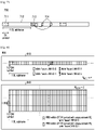
- Repetition of measurement RS can be illustrated in embodiment 600 of FIGURE 6 .
- one DL slot includes 7 OFDM symbols and one DL subframe includes two slots.
- time-domain repetition of measurement RS is performed across 4 consecutive OFDM symbols (denoted 611) within a subframe/slot that contains measurement RS.
- measurement RS is transmitted every other subframe/slot.
- time-domain repetition of measurement RS is performed across 4 consecutive slots where each instance of measurement RS occupies only 1 OFDM symbol (denoted 621).
- time-domain repetition of measurement RS is performed across 4 consecutive subframes where each instance of measurement RS occupies only 1 OFDM symbol (denoted 631).
- frequency-domain repetition of measurement RS is performed across 2 consecutive PRBs (demoted 641) within one OFDM symbol. Such an instance of measurement RS transmission is repeated in every other subframe/slot.
- All or at least one of the replicas or repetitions of measurement RS carry the same "beam” or radio resource (RR) ID.
- this measurement RS can be used for time and/or frequency tracking (fine timing/frequency acquisition).
- CSI-RS resource configuration also includes time-frequency CSI-RS pattern for one subframe/slot-PRB unit.
- a DL measurement RS can be configured for a UE using a CSI-RS resource configuration with the following features.
- a "beam" or radio resource ID is included in and can be detected from the measurement RS. This ID can be included either as a part of a RS bit sequence, encoded into a RS sequence, or encoded into a time-frequency pattern of the RS.
- the resource configuration includes the number of ports and time-frequency resolution (for OFDMA, the number of resource elements used across sub-carriers and OFDM symbols).
- the resource configuration also includes a repetition factor N REP,T in time domain and/or N REP,F in frequency domain that indicate the number of time-domain and/or frequency domain replicas, respectively.
- Time-domain repetition can be performed across time units such as across OFDM symbols, slots, or subframes. Frequency-domain repetition can be performed across frequency units such as across groups of sub-carriers, PRBs, or groups of PRBs. At least one of these parameters can be configured for a UE via higher-layer (RRC) signaling (for example, the number of ports, time-frequency pattern, and/or repetition factor). The rest of the parameters, if any, can be configured for a UE via L1/L2 control signaling. The configuration or reconfiguration can be done for UEs that are in a CONNECTED state.
- RRC higher-layer
- the configured number of (CSI-RS) ports can be the same or different from that used for CSI measurement. In general, however, a small number of antenna ports, such as one or two, can be used especially when beamforming is applied on measurement RS.
- a DL measurement RS can be configured periodically or aperiodically.
- a higher layer CSI-RS (or CSI-RS like) resource configuration that includes periodicity and reporting offset (such as subframe/slot offset) can be used. This configuration remains until reconfiguration occurs.
- a measurement RS indicator field can be included in a DL (L1) control signaling to indicate the presence of a DL measurement RS within the subframe/slot or TTI (or time unit used for packet scheduling). This is illustrated in a DL timing diagram embodiment 700 in FIGURE 7 .
- a DL control region 711 is transmitted at the beginning of the subframe/slot.
- a UE receives and attempts to detect either an assignment/grant for DL and/or UL transmissions in the remainder of the DL subframe/slot 712.
- the UE can attempt to detect the presence of a measurement RS indicator field.
- This RS indicator field can be included in a grant/assignment (either DL or UL) or signaled in a separate channel.
- this RS indicator field can be signaled as a UE-specific entity (hence masked or labeled with UE identification such as UE-specific RNTI or C-RNTI), or alternatively, a TRP/cell/RR common entity (hence masked or labeled with a TRP or cell or RR specific RNTI), or alternatively, UE-group-specific entity (such as group RNTI) where a DL control signaling conveys some control information pertaining to a group of UEs.
- the UE measures a DL measurement RS 714.
- the measurement RS indicator field 713 can include a trigger to indicate a one-shot measurement RS transmission (that is, the presence of measurement RS only in the same subframe/slot/TTI/scheduling time unit as the DL control that includes indicator field 713). Alternatively, it can include a trigger to indicate a multi-shot measurement RS transmission (that is, the presence of measurement RS in a plurality of subframes/TTIs/scheduling time units, starting either from the subframe/slot containing the indicator field 713 or a subframe/slot after, with a certain periodicity). In this case, a measurement RS indicator field activates or deactivates transmission and UE measurement of the DL measurement RS. Therefore, this scheme is applicable whether a DL measurement RS is transmitted and/or measured periodically or aperiodically.
- This measurement RS indicator field 713 can include only the trigger described above.
- this measurement RS indicator field can include (or be signaled together with) at least one more parameter such as that that indicates the location of the measurement RS, the time-frequency pattern of the RS, or the periodicity in case it is used for multi-shot transmission.
- embodiment I when multiple instances of DL measurement RS are transmitted or measured (that is, N REP,T > 1 or N REP,F > 1), different "beam"/RR IDS can be included in different instances of this DL measurement RS.
- embodiment 800 of FIGURE 8 illustrates this variation of embodiment I. In both embodiments 810 and 840, "beam"/RR IDs are cycled across different instances of DL measurement RS.
- PSS and SSS primary and secondary synchronization signals
- PSS/SSS is used for coarse timing and frequency synchronization and cell ID acquisition. Since PSS/SSS is transmitted twice per 10ms radio frame and time-domain enumeration is introduced in terms of System Frame Number (SFN, included in the MIB), frame timing is detected from PSS/SSS to avoid the need for increasing the detection burden from a physical broadcast channel (PBCH).
- PBCH physical broadcast channel
- CP cyclic prefix
- PBCH is primarily used to signal the Master Block Information (MIB) that includes DL and UL system bandwidth information (3 bits), PHICH information (3 bits), and SFN (3 bits). Adding 10 reserved bits (for other uses such as MTC), the MIB payload amounts to 24 bits.
- MIB Master Block Information
- a rate-1/3 tail-biting convolutional coding, 4x repetition, and QPSK modulation are applied to the 40-bit codeword.
- the resulting QPSK symbol stream is transmitted across 4 subframes spread over 4 radio frames.
- Other than detecting MIB blind detection of the number of cell-specific RS (CRS) ports is also needed for PBCH.
- CRS cell-specific RS
- TABLE 1 Example of contents of PSS/SSS and PBCH following LTE LTE PSS/SSS LTE PBCH Function Coarse time-frequency synchronization & cell ID acquisition MIB acquisition, [confirming cell ID acquisition] Parameters included Cell ID (504 hypotheses), frame timing (2 hypotheses) MIB: system BW (3 bits), PHICH info (3 bits), SFN (8 bits) + [10 reserved bits] Need for blind detection CP size (from SSS), [TDD vs. FDD] Number of CRS ports Reliability Low to moderate High (protected with 16-bit CRC + 1/48 effective code rate )
- nrSS in the present disclosure
- PBCH nrPBCH in the present disclosure, that includes MIB
- MIB payload can be minimized by not including PHICH information (that is not needed when the number of symbols used for DL control channel, such as PDCCH, does not change from subframe/slot to subframe/slot).
- PHICH information that is not needed when the number of symbols used for DL control channel, such as PDCCH, does not change from subframe/slot to subframe/slot.
- MIB includes DL and UL system bandwidth information and SFN, but not PHICH information.
- nrSS and nrPBCH are transmission bandwidth for nrSS and nrPBCH.
- DL numerology as discussed in FIGURE 5 , that can include CP length, sub-carrier spacing, and/or subframe/slot duration
- UE-specific or cell-specific feature or alternatively RRU-specific or "beam"-specific
- symbol or subframe/slot timing needs to be detected. In this case, what is a good mechanism to convey such timing information?
- the first issue is related to the minimum DL system bandwidth supported by NR.
- 20MHz DL reception is used for UE category 1 or above (a UE category is characterized by peak data rate and soft buffer size).
- the 1.4MHz (6-PRB) minimum BW is decided from network perspective (e.g. re-farming of GSM/GPRS carriers).
- PSS/SSS and PBCH are transmitted with a minimum and known bandwidth at a known location in frequency domain (center 6 PRBs). Since the location is fixed, there is no need for a UE to detect the location and transmission bandwidth for PSS/SSS and PBCH.
- System bandwidth information (that is cell-specific) is included in the MIB (hence transmitted via PBCH).
- nrSS and/or nrPBCH are system-bandwidth-dependent (transmitted with the same system bandwidth as other signals and channels - system bandwidth and nrSS/nrPBCH transmission bandwidth are different)
- system bandwidth information needs to be detected (either blindly or explicitly) from nrSS.
- this option is less preferred due to reliability issue of nrSS.
- the number of possible system bandwidth values at least 8 - from LTE, and possibly more for NR) and location hypotheses can be too large to be included in nrSS.
- nrSS that can include nrPSS and nrSSS
- nrPBCH are transmitted with a known bandwidth (such as the minimum system bandwidth).
- system bandwidth information that is used for other signals and channels (such as PDSCH or PUSCH) is included in the MIB. This system bandwidth information can represent all the possible system bandwidth values.
- nrSS that can include nrPSS and nrSSS
- system bandwidth information that is used for other signals and channels (such as PDSCH or PUSCH) is included in the MIB. This (full) system bandwidth information can represent all the possible system bandwidth values.
- partial system bandwidth information can be included in the MIB. Examples of such a correspondence are given in the tables below.
- bandwidth can be described either in terms of a number of frequency-domain resource blocks (such as that analogous to RB or PRB in LTE) or in Hertz (Hz).
- frequency-domain resource blocks such as that analogous to RB or PRB in LTE
- Hz Hertz
- nrSS and nrPBCH are transmitted with (occupy) the same bandwidth.
- nrSS and/or nrPBCH occupy one of the two bandwidth values ( BW 1 or BW 2 where BW 1 ⁇ BW 2 ).
- the transmission bandwidth for nrSS/nrPBCH can either be signaled via nrSS (such as nrSSS, hence doubling the number of hypotheses in nrSS) or blindly detected from nrSS and/or nrPBCH.
- nrSS such as nrSSS, hence doubling the number of hypotheses in nrSS
- nrPBCH blindly detected from nrSS and/or nrPBCH.
- nrSS is transmitted with (occupies) one bandwidth value BW 1
- nrPBCH can be transmitted (occupy) one of the two bandwidth values ( BW 1 and BW 2 ).
- nrPBCH occupies one of the two bandwidth values ( BW 1 or BW 2 where BW 1 ⁇ BW 2 ).
- the transmission bandwidth for nrPBCH can either be signaled via nrSS (such as nrSSS, hence doubling the number of hypotheses in nrSS), nrPBCH (hence doubling the number of hypotheses in the MIB), or blindly detected from nrPBCH.
- TABLE 2B Example correspondence between system bandwidth and nrSS/nrPBCH transmission bandwidth
- nrSS includes nrPSS and nrSSS where nrPSS is transmitted with (occupies) one bandwidth value BW 1 , while nrSSS and nrPBCH can be transmitted (occupy) one of the two bandwidth values ( BW 1 and BW 2 ).
- nrSSS and nrPBCH occupy one of the two bandwidth values ( BW 1 or BW 2 where BW 1 ⁇ BW 2 ).
- the transmission bandwidth for nrSSS and nrPBCH can either be signaled via nrSS (such as nrSSS, hence doubling the number of hypotheses in nrSS), nrPBCH (hence doubling the number of hypotheses in the MIB), or blindly detected from nrSSS and/or nrPBCH.
- nrSS such as nrSSS
- nrPBCH doubling the number of hypotheses in the MIB
- TABLE 2C Example correspondence between system bandwidth and nrSS/nrPBCH transmission bandwidth
- System bandwidth nrPSS bandwidth nrSSS bandwidth nrPBCH bandwidth System BW ⁇ BW 2 BW 1 BW 1 BW 1 System BW > BW 2 BW 2 BW 2
- nrSS/nrPBCH one fixed and known location of nrSS/nrPBCH is used, at least for a given scenario (such as for a carrier frequency). However, this does not preclude having different frequency-domain locations for different scenarios.
- TABLE 2C can be extended in either TABLE 2D (where nrSSS and nrPBCH can be transmitted (occupy) one bandwidth value) or TABLE 2E (where nrSSS and nrPBCH can be transmitted (occupy) one of two bandwidth values).
- nrSS/nrPBCH one fixed and known location of nrSS/nrPBCH is used, at least for a given scenario (such as for a carrier frequency). However, this does not preclude having different frequency-domain locations for different scenarios.
- At least one of nrPSS and nrSSS, and/or nrPBCH occupy a set of frequency-domain resources (transmission bandwidth) that scales with sub-carrier spacing (nrSS can be transmitted with variable numerology). This is relevant when at least one of nrPSS and nrSSS is transmitted with variable sub-carrier spacing.
- nrPSS is transmitted in this manner, one common sequence is used for nrPSS irrespective of the sub-carrier spacing.
- nrSSS is transmitted in this manner, one common sequence is used for nrSSS irrespective of the sub-carrier spacing.
- numerology (that includes any combination of CP length, sub-carrier spacing, and/or subframe/slot length) for data and/or dedicated control can either be UE-specific or cell- (or "RRU"-) specific. This can be related to whether nrSS and/or nrPBCH are transmitted with fixed/common numerology.
- numerology information is configured via higher-layer signaling (that is, RRC-configured).
- TRP time-division multiplexing
- FDM frequency-division multiplexing
- SDM space-division multiplexing, such as multi-user MIMO
- the numerology is cell/RRU-specific (hence common for all UEs within a cell/RRU)
- numerology information can be signaled either in MIB or SIB-x as a part of broadcast information.
- nrSS that can include nrPSS and nrSSS
- nrPBCH transmission as well as other common channels
- a fixed and common numerology is used for nrSS (that can include nrPSS and nrSSS) and nrPBCH transmission.
- nrSS that can include nrPSS and nrSSS
- nrPBCH transmission
- a fixed and common sub-carrier spacing is used.
- cell-specific numerology information (such as sub-carrier spacing) can be included in the MIB to allow variable numerology for system information (SI-x) transmission.
- SI-x system information
- a designated DL assignment can be used for indicating a transmission of system information in a given TTI where the DL assignment also carries an indicator analogous to LTE's SI-RNTI.
- system information can be received by a UE after the UE decodes the MIB from nrPBCH.
- variable numerology can be used for nrSS (that can include nrPSS and nrSSS) and nrPBCH transmission where all the possible values of sub-carrier spacing used for data channel transmission are applicable.
- variable sub-carrier spacing one value selected from ⁇ 15, 30, 60, 120 ⁇ kHz
- nrSS that can include nrPSS and nrSSS
- nrPBCH transmission bandwidth
- the transmission bandwidth depends on whether a common synchronization sequence is used for nrPSS and/or nrSSS transmitted with different values of sub-carrier spacing. If a common sequence is used, transmission bandwidth linearly scales with the value of sub-carrier spacing.
- sub-carrier spacing (as well as transmission bandwidth) is to be assumed at the UE for receiving and demodulating nrPSS/nrSSS, sub-carrier spacing (as well as transmission bandwidth) can be detected blindly at the UE. That is, the UE can repeat reception and demodulation of nrPSS/nrSSS by assuming different values of sub-carrier spacing (as well as transmission bandwidth).
- variable numerology can be used for nrSS (that can include nrPSS and nrSSS) and nrPBCH transmission where only a subset of all the possible values of sub-carrier spacing used for data channel transmission are applicable. For example, if ⁇ 15, 30, 60, 120 ⁇ kHz can be used for data channel transmission, variable sub-carrier spacing (one value selected from ⁇ 15, 60 ⁇ kHz) can be used for nrSS (that can include nrPSS and nrSSS) and nrPBCH transmission.
- the transmission bandwidth depends on whether a common synchronization sequence is used for nrPSS and/or nrSSS transmitted with different values of sub-carrier spacing.
- sub-carrier spacing (as well as transmission bandwidth) is to be assumed at the UE for receiving and demodulating nrPSS/nrSSS, sub-carrier spacing (as well as transmission bandwidth) can be detected blindly at the UE. That is, the UE can repeat reception and demodulation of nrPSS/nrSSS by assuming different values of sub-carrier spacing (as well as transmission bandwidth).
- cell-specific numerology information (such as sub-carrier spacing) can be included in the MIB to allow variable numerology for system information (SI-x) transmission.
- SI-x system information
- a designated DL assignment can be used for indicating a transmission of system information in a given TTI where the DL assignment also carries an indicator analogous to LTE's SI-RNTI.
- system information can be received by a UE after the UE decodes the MIB from nrPBCH.
- full cell-specific numerology information (such as sub-carrier spacing) is included in the MIB. This is relevant when there is no correlation between the numerology used for nrSS and nrPBCH and the numerology used for system information transmission.
- partial cell-specific numerology information (such as sub-carrier spacing) is included in the MIB. This is relevant when there is some correlation between the numerology used for nrSS and nrPBCH and the numerology used for system information transmission. For example, when 15kHz sub-carrier spacing is for nrSS/nrPBCH, possible sub-carrier spacing values for system information transmission can be either 15kHz or 30kHz. When 60kHz sub-carrier spacing is for nrSS/nrPBCH, possible sub-carrier spacing values for system information transmission can be either 60kHz or 120kHz.
- UE-specific numerology for data and/or dedicated control transmission can be used in conjunction with cell-specific numerology for common channel/signal (such as nrPSS, nrSSS, and/or nrPBCH) transmission.
- the cell-specific numerology for common channel/signal is either known or detected from at least one of the common channel/signals.
- this cell-specific numerology corresponds to sub-carrier spacing. Since the same sub-carrier spacing is used for nrPBCH, the acquired knowledge of cell-specific sub-carrier spacing can be used to decode the MIB from nrPBCH in step 920.
- the UE has established an RRC connection with a TRP or a cell (hence in RRC _CONNECTED state) (step 950).
- the UE can receive RRC configurations including UE-specific numerology configuration that is used for data and dedicated control transmission.
- N multiple ( N >1) transmissions of nrSS (that can include nrPSS and nrSSS) and/or nrPBCH within one transmission period (for instance, 10ms radio frame) across N OFDM symbols implies that timing information, such as symbol timing, needs to be detected by a UE.
- symbol timing refers to the symbol number (or index) within one transmission period or one subframe/slot.
- nrSS/nrPBCH is repeated N times across N OFDM symbols.
- the purpose of such repetition is to enhance nrSS/nrPBCH coverage within one transmission period.
- N should be taken into account by a UE.
- the value of N can either be fixed in the specification (hence signaling or blind decoding is not needed) or varied (hence blind detection is needed). If timing needs to be detected, it is automatically detected upon nrSS acquisition.
- nrSS that can include nrPSS and nrSSS
- nrPBCH are transmitted with multiple N >1 copies across N OFDM symbols within one transmission period.
- the value of N can either be fixed in the specification (hence signaling or blind decoding is not needed) or varied (hence blind detection is needed).
- nrSS/nrPBCH beam cycling or beam sweeping across N beams across N OFDM symbols is applied on nrSS/nrPBCH.
- This scenario is especially relevant when mmWave analog/hybrid beamforming architecture (also termed the "multi-beam" architecture) is used. Therefore, for each of nrPSS, nrSSS, and nrPBCH, different beams are used across N different symbols.
- the coverage gain from beamforming can be obtained from detecting and demodulating only one of N symbols. Therefore, the value of N does not need to be taken into account by the UE. That is, N can be made transparent to the UE during nrSS acquisition.
- timing hypothesis needs to be detected either during nrSS (either explicit hypotheses or blind detection) or nrPBCH (either explicit hypotheses or blind detection) acquisition. The following option embodiments are applicable.
- nrSS that can include nrPSS and nrSSS
- nrPBCH are transmitted N times across N OFDM symbols within one transmission period.
- the value of N is neither specified nor detected by the UE.
- Timing information is included in nrSS (either in nrPSS or nrSSS).
- This timing information can be a symbol timing parameter that corresponds to a symbol index within one subframe/slot or TTI. For example, if one subframe/slot or TTI includes N SYM OFDM symbols, the value of the symbol index ranges from 0 to ( N SYM -1) .
- the symbol timing parameter can correspond to a symbol index within one radio frame or one transmission period for nrSS/nrPBCH. This timing information is to be detected by the UE upon receiving nrSS (either nrPSS or nrSSS).
- nrSS that can include nrPSS and nrSSS
- nrPBCH are transmitted N times across N OFDM symbols within one transmission period.
- the value of N is neither specified nor detected by the UE.
- Timing is included in the MIB (and hence in nrPBCH).
- This timing information can be a symbol timing parameter that corresponds to a symbol index within one subframe/slot or TTI. For example, if one subframe/slot or TTI includes N SYM OFDM symbols, the value of the symbol index ranges from 0 to ( N SYM -1).
- the symbol timing parameter can correspond to a symbol index within one radio frame or one transmission period for nrSS/nrPBCH.
- This timing information is to be detected by the UE.
- This timing information is to be detected by the UE upon decoding the MIB from nrPBCH.
- nrSS that can include nrPSS and nrSSS
- nrPBCH are transmitted N times across N OFDM symbols within one transmission period.
- the value of N is neither specified nor detected by the UE.
- Timing information (such as symbol timing, either within a subframe/slot or a radio frame or a transmission period) is not included in nrSS or nrPBCH. Therefore, this timing information is to be detected blindly from either nrSS or nrPBCH or both.
- TABLE 3 Parameters included in nrSS and nrPBCH - examples
- Example Synchronization signals nrSS (nrPSS/nrSSS) Primary BCH: nrPBCH
- System bandwidth information included in the MIB can include both DL and UL system bandwidth information. Alternatively, only DL system bandwidth information is included in the MIB while UL system bandwidth information is included as a part of system information.
- Numerology information in the MIB can include one or a plurality of parameters such as sub-carrier spacing, CP length, and/or OFDM symbol duration (or subframe/slot length).
- a variation of the above examples can be devised by including a need for blind detection of transmission bandwidth associated with at least one of nrPSS, nrSSS, and nrPBCH.
- This transmission bandwidth is not the same as the system bandwidth.
- the transmission bandwidth of nrPSS, nrSSS, and/or nrPBCH can be correlated with the system bandwidth as described in TABLE 2A, 2B, 2C, 2D, and 2E.
- the payload associated with system bandwidth information included in the MIB can be reduced since the system bandwidth can be inferred from both transmission bandwidth of nrPSS/nrSSS/nrPBCH and the system bandwidth information in the MIB.
- Another variation of the above examples can be devised by including a need for blind detection of cell-specific numerology information from at least one of nrPSS and nrSSS (see method 900 of FIGURE 9 ). This is relevant, for example, when nrPSS/nrSSS/nrPBCH can be transmitted with variable sub-carrier spacing. In this case, a UE performs blind detection of sub-carrier spacing from nrPSS and/or nrSSS.
- cell-specific numerology information such as cell-specific sub-carrier spacing can be detected from nrPSS and/or nrSSS in the variation described in the preceding paragraph
- another variation is to include this cell-specific numerology information in the MIB (such as in examples A1, A2, and A3). Therefore, this cell-specific numerology is not used for nrPSS and/or nrSSS. But it can be used for at least one of nrPBCH as well as transmission resource in the data channel containing System Information.
- cell-specific numerology information is neither included in nor blindly detected from nrPSS/nrSSS/nrPBCH.
- common signals/channels including nrPSS, nrSSS, nrPBCH, and/or transmission resource carrying System Information
- common numerology such as sub-carrier spacing
- symbol timing is blindly detected from nrPBCH.
- symbol timing can be blindly detected from nrPSS and/or nrSSS.
- synchronization signal includes primary and secondary synchronization signals (PSS and SSS, or nrPSS and nrSSS).
- nrSS includes nrPSS (primarily intended for coarse time-frequency synchronization) and nrSSS (primarily intended for cell ID detection), each of that can be transmitted either periodically or aperiodically.
- nrPSS and nrSSS are transmitted either once or N >1 times per radio frame.
- transmitting nrPSS or nrSSS multiple times is intended to enhance coverage via, for instance, beam sweeping.
- nrPSS and/or nrSSS can be transmitted in any subframe/slot or a subframe/slot within a set of allowable nrSS subframes.
- nrPSS corresponds to a common primary synchronization sequence for a given value of cell ID. Therefore, the primary synchronization sequence does not carry any partial cell ID information. If variable numerology (such as variable sub-carrier spacing) can be used for nrPSS, either a common primary synchronization sequence is used for all possible values of sub-carrier spacing (thereby resulting in variable transmission bandwidth) or one distinct primary synchronization sequences can be used for one value of sub-carrier spacing. That is, primary synchronization sequence is sub-carrier-spacing-specific.
- variable numerology such as variable sub-carrier spacing
- nrPSS can carry one out of K >1 primary synchronization sequences (analogous to LTE) wherein each sequence is associated with a subset of cell ID values. Therefore, primary synchronization sequence carries partial cell ID information. If variable numerology (such as variable sub-carrier spacing) can be used for nrPSS, either a common set of K primary synchronization sequences is used for all possible values of sub-carrier spacing (thereby resulting in variable transmission bandwidth) or one distinct set of K primary synchronization sequences can be used for one value of sub-carrier spacing. That is, the set of K primary synchronization sequences is sub-carrier-spacing-specific.
- variable numerology such as variable sub-carrier spacing
- format can include any one or combination of sub-carrier spacing, time-frequency location, sequence design (type and/or length), transmission bandwidth, and/or CP length for one transmission instance of nrPSS and/or nrSSS. Therefore, two different formats are differentiated by at least one numerology parameter. This facilitates a UE to perform blind detection of the nrSSS format. That is, cell ID decoding attempt is repeated across all the possible format hypotheses.
- Q PSS 1 (a single format nrPSS) is used while Q SSS > 1 (multi-format nrSSS) is used for different use cases.
- Examples of two-format nrSSS design (with a single format nrPSS) are given in TABLE 4.
- An example of a single-format nrPSS is to transmit nrPSS with a fixed and common sub-carrier spacing. TABLE 4.
- Examples of two-format ( Q PSS 2) nrSSS Ex.
- the one common nrPSS format used for both nrSSS formats is utilized primarily for coarse time-frequency synchronization. In this case, a narrow transmission bandwidth for nrPSS can be used.
- the UE can acquire information on use case(s), such as single- versus multi-beam access, partial numerology information (sub-carrier spacing and/or transmission bandwidth of nrSSS).
- Examples 2 and 5 are illustrated in embodiments 1000 and 1010 of FIGURE 10 , respectively.
- the number of OFDM symbols per subframe/slot (7) used in these examples is chosen for illustrative purposes. Extension to other examples can be straightforwardly inferred by those familiar with the art.
- nrPSS and format 1 nrSSS are multiplexed in time-domain across two OFDM symbols (1001) while nrPSS and format 2 nrSSS are multiplexed in frequency-domain within one OFDM symbol (1002).
- the transmission bandwidth for nrPSS remains the same (single-valued) while the transmission bandwidth for format 2 nrSSS is larger than that of format 1 nrSSS and nrPSS.
- nrPSS and format 1 nrSSS are multiplexed in time-domain across two OFDM symbols (1011) while nrPSS and format 2 nrSSS are also multiplexed in time-domain across two OFDM symbols (1012).
- the transmission bandwidth for nrPSS remains the same (single-valued) while the transmission bandwidth for format 2 nrSSS is larger than that of format 1 nrSSS and nrPSS.
- Q PSS > 1 (a multi-format nrPSS) is used.
- Each of the Q PSS nrPSS formats can be associated with a certain use case.
- Q SSS > 1 nrSSS formats are used in the same manner as the previous embodiment I.
- each of the Q PSS nrPSS formats is associated with a distinct sub-carrier spacing value (hence a total of Q PSS sub-carrier spacing values).
- Yet another sub-embodiment can be designed by combining sub-embodiment II.1 with a previous embodiment where the transmission bandwidths of nrPSS and nrSSS scale with sub-carrier spacing.
- a same (common) primary synchronization sequence can be used for different values of sub-carrier spacing.
- sequence length remains the same for different values of sub-carrier spacing.
- ⁇ SCS denotes the sub-carrier spacing that is variable (such as ⁇ 15, 30, 60, 120 ⁇ kHz or ⁇ 15, 60 ⁇ kHz).
- the constants A and B can be chosen such that A ⁇ max ⁇ ⁇ SCS ⁇ ⁇ B ⁇ min ⁇ ⁇ SCS ⁇ or, alternatively, the sets ⁇ A ⁇ ⁇ SCS ⁇ and ⁇ B ⁇ ⁇ SCS ⁇ do not intersect with each other.
- the constants A and B can be chosen such that A ⁇ max ⁇ ⁇ SCS ⁇ ⁇ B ⁇ min ⁇ ⁇ SCS ⁇ or, alternatively, the sets ⁇ A ⁇ ⁇ SCS ⁇ and ⁇ B ⁇ ⁇ SCS ⁇ do not intersect with each other.
- the constants A, B , and C can be chosen such that A ⁇ max ⁇ ⁇ SCS ⁇ ⁇ B ⁇ min ⁇ ⁇ SCS ⁇ , A ⁇ max ⁇ ⁇ SCS ⁇ ⁇ C ⁇ min ⁇ ⁇ SCS ⁇ , and the sets ⁇ B ⁇ ⁇ SCS ⁇ and ⁇ C ⁇ ⁇ SCS ⁇ do not intersect with each other.
- the constants A , B, and C can simply be chosen such that the sets ⁇ A ⁇ ⁇ SCS ⁇ , ⁇ B ⁇ ⁇ SCS ⁇ , and ⁇ C ⁇ ⁇ SCS ⁇ do not intersect with each other.
- sub-carrier spacing can be detected when a UE attempts to acquire coarse timing and frequency offset upon receiving nrPSS. Having detected the sub-carrier spacing, the UE proceeds in demodulating nrSSS by detecting cell ID and nrSSS format (for instance, 1 or 2) from nrSSS. This detected format can be associated with a certain use case or numerology parameter.
- nrPSS and nrSSS are transmitted with variable sub-carrier spacing.
- sub-carrier spacing are shown (1101 for 15kHz, 1111 for 30kHz) for illustrative purposes.
- Extension to other values of sub-carrier spacing can be straightforwardly inferred by those skilled in the art.
- nrPSS When nrPSS is multiplexed with nrSSS format 1, the transmission bandwidth of nrPSS and nrSSS is A ⁇ (15 kHz ) and A ⁇ (30 kHz ) for 15kHz and 30kHz sub-carrier spacing, respectively.
- nrPSS When nrPSS is multiplexed with nrSSS format 2, the transmission bandwidth of nrPSS remains A ⁇ (15 kHz ) and A ⁇ (30 kHz ) for 15kHz and 30kHz sub-carrier spacing, respectively.
- the transmission bandwidth for nrSSS is B ⁇ (15 kHz ) and B ⁇ (30 kHz ) for 15kHz and 30kHz sub-carrier spacing, respectively.
- a UE is able to detect sub-carrier spacing and format information from nrPSS and nrSSS in addition to cell ID and coarse timing-frequency acquisition.
- nrPBCH design A first issue on nrPBCH design is the transmission properties of nrPBCH. Since nrPBCH can be demodulated right after a UE detects nrSSS, it is expected that nrPBCH share at least some of the transmission properties of either nrPSS or nrSSS.
- nrPBCH can share some of the transmission properties of either nrPSS or nrSSS.
- Such features include transmission bandwidth (as previously defined), frequency-domain location(s), sub-carrier spacing, and nrPBCH symbol duration (per transmission instance).
- nrSSS transmission properties are different from nrPSS, nrPBCH can share the same transmission properties as nrSSS.
- nrPBCH design A second issue on nrPBCH design is a signal (or signals) that can be used as a reference signal for demodulating nrPBCH.
- PBCH demodulation uses CRS (where the same number of antenna ports is used for PBCH and transmission mode 3 or 4).
- CRS where the same number of antenna ports is used for PBCH and transmission mode 3 or 4.
- different reference signals (RSs) for measurement and demodulation (each possibly UE-specific) will most likely be used for data demodulation and CSI measurements.
- an always-on reference signal will most likely not available.
- a low channel coding rate cf.
- any UE-transparent transmit diversity (that uses one antenna port for a given transmission instance) is expected to perform as well as full-diversity space-frequency block code (SFBC, such as the Alamouti code).
- SFBC space-frequency block code
- a UE can assume that nrPBCH is transmitted along one antenna port, and the one antenna port is common (shared) with at least one of nrPSS and nrSSS. This facilitates, for example, the use of UE-transparent transmit beamforming or beam sweeping to enhance the coverage of nrPSS, nrSSS, and/or nrPBCH.
- nrSSS can nrPBCH can be designed in such a way that nrSSS can be used for demodulating nrPBCH (that is, nrSSS can function as a demodulation RS for nrPBCH). This can be done regardless whether a special demodulation RS is allocated within the OFDM symbols where nrPBCH is transmitted.
- nrSSS can function as a demodulation RS for nrPBCH.
- nrPSS nrSSS
- nrPBCH nrPBCH
- nrPSS is transmitted in one symbol while nrSSS and nrPBCH are transmitted in another symbol with nrSSS and nrPBCH interleaved across REs in frequency domain.
- N >1 beams this transmission pattern is repeated N times where a triplet of nrPSS-nrSSS/nrPBCH (such as 1216) share a same antenna port.
- nrSSS and nrPBCH experience the same channel and transmit beamforming.
- nrPSS, nrSSS, and nrPBCH are transmitted in one symbol as well as interleaved across REs in frequency domain.
- this transmission pattern is repeated N times where a triplet of nrPSS/nrSSS/nrPBCH (such as 1226) share a same antenna port.
- nrSSS and nrPBCH experience the same channel and transmit beamforming.
- Each of the three options can be used in combination with the multi-format nrPSS/nrSSS embodiments in component 2 (previous section).
- Q SSS 2
- embodiment 1200 can be used for format 1 nrSSS (with N >1) and embodiment 1225 can be used for format 2 nrSSS (with N >1).
- DFT-S-OFDM whenever DFT-S-OFDM is used, a single-carrier version of DFT-S-OFDM (single-carrier FDMA, SC-FDMA) where a UE is configured to transmit on a set of contiguous PRBs can be used.
- the names for UL transmission channels or waveforms are example and can be substituted with other names or labels without changing the substance and /or function of this embodiment.
- FIGURE 13 illustrates a flowchart for an example method 1300 wherein a UE receives a primary synchronization signal (PSS), a secondary synchronization signal (SSS), and a primary broadcast channel (PBCH) according to an embodiment of the present disclosure.
- PSS primary synchronization signal
- SSS secondary synchronization signal
- PBCH primary broadcast channel
- the method 900 can be performed by the UE 116.
- the method 1300 begins with the UE receiving the PSS, the SSS, and the PBCH wherein the PSS, the SSS, and the PBCH are time-division multiplexed (step 1301). In addition, a same set of sequences are used for the PSS and the SSS for different carrier frequencies and different sub-carrier spacing values. From at least the PSS and the SSS, cell identification (cell ID) information is decoded (step 1302). Cell ID detection can be performed along with time and/or frequency acquisition (especially during initial access). The cell ID signifies the cell in which the UE is served. After decoding the cell ID, the UE proceeds with decoding a master information block (MIB) from the PBCH (step 1303).
- MIB master information block
- the PSS For different carrier frequencies and/or different sub-carrier spacing values, a same set of sequences (hence a same sequence length) are used for the PSS. Therefore, the number of sub-carriers used for PSS is the same for different carrier frequencies. The same holds for the SSS.
- the PSS, the SSS, and the PBCH can be transmitted using a same single antenna port. Therefore, the UE can assume that all the three signals share the same channel characteristics.
- timing information within each radio frame can be signaled via the PBCH or, more specifically, included in the MIB. Therefore, the UE extracts the radio frame timing information from the PBCH (or the MIB) (step 1304).
- the number of sub-carriers used for the PSS is the same as that for the SSS. In another embodiment, the number of sub-carriers used for the SSS is the same as that for the PBCH. In another embodiment, the number of sub-carriers used for the PSS is the same as that for the SSS, but smaller than that for the PBCH.
- FIGURE 14 illustrates a flowchart for an example method 1400 wherein a BS transmits a primary synchronization signal (PSS), a secondary synchronization signal (SSS), and a primary broadcast channel (PBCH) according to an embodiment of the present disclosure.
- PSS primary synchronization signal
- SSS secondary synchronization signal
- PBCH primary broadcast channel
- the method 1400 can be performed by the BS 102.
- the method 1400 begins with the BS including radio timing information in PBCH or, more specifically in a Master Information Block (MIB) (step 1401).
- the MIB is encoded in the PBCH (step 1402) and cell identification (cell ID) information is encoded at least in the PSS and/or SSS.
- the cell ID signifies the cell in which a UE is served (step 1403).
- the BS then transmits the PSS, the SSS, and the PBCH in a time-division duplexing manner.
- the PSS For different carrier frequencies and/or different sub-carrier spacing values, a same set of sequences (hence a same sequence length) are used for the PSS. Therefore, the number of sub-carriers used for PSS is the same for different carrier frequencies. The same holds for the SSS.
- the PSS, the SSS, and the PBCH can be transmitted using a same single antenna port. Furthermore, timing information within each radio frame can be signaled via the PBCH or, more specifically, included in the MIB.
- the number of sub-carriers used for the PSS is the same as that for the SSS. In another embodiment, the number of sub-carriers used for the SSS is the same as that for the PBCH. In another embodiment, the number of sub-carriers used for the PSS is the same as that for the SSS, but smaller than that for the PBCH.
- FIGURES 13 and 14 illustrate examples of methods for receiving configuration information and configuring a UE, respectively, various changes could be made to FIGURES 13 and 14 .
- steps in each figure could overlap, occur in parallel, occur in a different order, occur multiple times, or not be performed in one or more embodiments.
- an apparatus of a terminal comprising: a transceiver configured to receive a primary synchronization signal (PSS), a secondary synchronization signal (SSS), and a primary broadcast channel (PBCH); and a processor operably connected to the transceiver, the processor configured to decode cell identification information from at least the PSS and the SSS and to decode a master information block (MIB) from the PBCH; wherein the PSS, the SSS, and the PBCH are time-division multiplexed, and wherein a same set of sequences are used for the PSS and the SSS for different carrier frequencies and different sub-carrier spacing values.
- PSS primary synchronization signal
- SSS secondary synchronization signal
- PBCH primary broadcast channel
- MIB master information block
- the apparatus of aspect 1 wherein the PSS, the SSS, and the PBCH are transmitted using a same single antenna port.
- the apparatus of aspect 1 is provided, wherein timing information within each radio frame is signaled via the PBCH.
- the apparatus of aspect 3 is provided, wherein the timing information is included in the MIB.
- the apparatus of aspect 2 wherein a number of sub-carriers used for the PSS is the same as a number of sub-carriers used for the SSS.
- the apparatus of aspect 2 wherein a number of sub-carriers used for the SSS is the same as a number of sub-carriers used for the PBCH.
- a number of sub-carriers used for the PSS is the same as a number of sub-carriers used for the SSS and smaller than a number of sub-carriers used for the PBCH.
- an apparatus of a base station comprising: a processor configured to: encode cell identification information in at least a primary synchronization signal (PSS) and a secondary synchronization signal (SSS); encode a master information block (MIB) in a primary broadcast channel (PBCH); and a transceiver operably connected to the processor, the transceiver configured to transmit the PSS, the SSS, and the PBCH; wherein the PSS, the SSS, and the PBCH are time-division multiplexed, and wherein a same set of sequences are used for the PSS and the SSS for different carrier frequencies and different sub-carrier spacing values.
- PSS primary synchronization signal
- SSS secondary synchronization signal
- MIB master information block
- PBCH primary broadcast channel
- the apparatus of aspect 8 wherein the PSS, the SSS, and the PBCH are transmitted using a same single antenna port.
- the apparatus of aspect 8 is provided, wherein timing information within each radio frame is signaled via the PBCH.
- the apparatus of aspect 8 is provided, wherein the timing information is included in the MIB.
- the apparatus of aspect 8 is provided, wherein a number of sub-carriers used for the PSS is the same as a number of sub-carriers used for the SSS.
- the apparatus of aspect 8 wherein a number of sub-carriers used for the PSS is the same as a number of sub-carriers used for the SSS and smaller than a number of sub-carriers used for the PBCH.
- a fourteenth aspect a method for operating a terminal configured to implement one of aspects 1 to 7 is provided.
- a method for operating a base station configured to implement one of aspects 8 to 13 is provided.
Landscapes
- Engineering & Computer Science (AREA)
- Signal Processing (AREA)
- Computer Networks & Wireless Communication (AREA)
- Physics & Mathematics (AREA)
- Mathematical Physics (AREA)
- Mobile Radio Communication Systems (AREA)
Applications Claiming Priority (5)
| Application Number | Priority Date | Filing Date | Title |
|---|---|---|---|
| US201662347958P | 2016-06-09 | 2016-06-09 | |
| US201662372602P | 2016-08-09 | 2016-08-09 | |
| US15/618,014 US10512046B2 (en) | 2016-06-09 | 2017-06-08 | Method and apparatus for measurement reference signal and synchronization |
| EP17810584.7A EP3469748B1 (fr) | 2016-06-09 | 2017-06-09 | Procédé et appareil pour signal de référence et synchronisation de mesure |
| PCT/KR2017/006026 WO2017213461A1 (fr) | 2016-06-09 | 2017-06-09 | Procédé et appareil pour signal de référence et synchronisation de mesure |
Related Parent Applications (2)
| Application Number | Title | Priority Date | Filing Date |
|---|---|---|---|
| EP17810584.7A Division EP3469748B1 (fr) | 2016-06-09 | 2017-06-09 | Procédé et appareil pour signal de référence et synchronisation de mesure |
| EP17810584.7A Division-Into EP3469748B1 (fr) | 2016-06-09 | 2017-06-09 | Procédé et appareil pour signal de référence et synchronisation de mesure |
Publications (2)
| Publication Number | Publication Date |
|---|---|
| EP4089970A2 true EP4089970A2 (fr) | 2022-11-16 |
| EP4089970A3 EP4089970A3 (fr) | 2023-01-04 |
Family
ID=60573435
Family Applications (2)
| Application Number | Title | Priority Date | Filing Date |
|---|---|---|---|
| EP22183015.1A Pending EP4089970A3 (fr) | 2016-06-09 | 2017-06-09 | Procédé et appareil de mesure et de synchronisation de signal de référence |
| EP17810584.7A Active EP3469748B1 (fr) | 2016-06-09 | 2017-06-09 | Procédé et appareil pour signal de référence et synchronisation de mesure |
Family Applications After (1)
| Application Number | Title | Priority Date | Filing Date |
|---|---|---|---|
| EP17810584.7A Active EP3469748B1 (fr) | 2016-06-09 | 2017-06-09 | Procédé et appareil pour signal de référence et synchronisation de mesure |
Country Status (4)
| Country | Link |
|---|---|
| US (2) | US10512046B2 (fr) |
| EP (2) | EP4089970A3 (fr) |
| CN (1) | CN109314592B (fr) |
| WO (1) | WO2017213461A1 (fr) |
Families Citing this family (50)
| Publication number | Priority date | Publication date | Assignee | Title |
|---|---|---|---|---|
| EP4131877A1 (fr) | 2016-03-10 | 2023-02-08 | IDAC Holdings, Inc. | Détermination d'une structure de signal dans un système sans fil |
| US11038557B2 (en) * | 2016-03-31 | 2021-06-15 | Samsung Electronics Co., Ltd. | Method and apparatus for transmitting and receiving reference signals in wireless communication |
| EP4075704A1 (fr) | 2016-05-11 | 2022-10-19 | IDAC Holdings, Inc. | Solutions de couche physique (phy) pour prendre en charge l'utilisation de numérologies mixtes dans le même canal |
| EP3479636B1 (fr) * | 2016-06-30 | 2024-01-03 | Nec Corporation | Procédé et appareil de configuration de signal dans un système de communication sans fil |
| JP2019145867A (ja) * | 2016-07-05 | 2019-08-29 | シャープ株式会社 | 基地局装置、端末装置および通信方法 |
| WO2018012882A1 (fr) * | 2016-07-12 | 2018-01-18 | Lg Electronics Inc. | Procédé et appareil servant à exécuter un alignement basé sur une mini sous-trame pour une nouvelle technologie d'accès radio dans un système de communication sans fil |
| KR102178412B1 (ko) * | 2016-07-15 | 2020-11-16 | 주식회사 케이티 | 새로운 무선 액세스 망에서 단말을 위한 동기화 신호 및 시스템 정보를 송수신하는 방법 및 장치 |
| CN107623932B (zh) * | 2016-07-15 | 2019-08-30 | 电信科学技术研究院 | 一种系统信息区域或网络区域的接入方法及装置 |
| RU2738349C2 (ru) * | 2016-08-10 | 2020-12-11 | Идак Холдингз, Инк. | Способы гибкого использования ресурсов |
| CN109565484B (zh) * | 2016-08-10 | 2021-02-09 | 华为技术有限公司 | 用于支持不同子载波间隔的新无线载波的公共同步信号 |
| CN107733828B (zh) * | 2016-08-12 | 2020-10-09 | 电信科学技术研究院 | 一种确定基带参数的方法和设备 |
| US10805893B2 (en) * | 2016-08-19 | 2020-10-13 | Samsung Electronics Co., Ltd | System and method for providing universal synchronization signals for new radio |
| JP6828808B2 (ja) * | 2016-08-24 | 2021-02-10 | 日本電気株式会社 | 5g無線通信システムにおける適応無線アクセス技術を実現するためのシステム及び方法 |
| US10631299B2 (en) * | 2016-09-08 | 2020-04-21 | Qualcomm Incorporated | Transmission scheme management for common channels in NR |
| US10447517B2 (en) * | 2016-09-27 | 2019-10-15 | Qualcomm Incorporated | Methods and apparatus for using synchronization signals as reference for demodulating multi-port broadcast channel |
| US10862663B2 (en) * | 2016-09-29 | 2020-12-08 | Qualcomm Incorporated | Devices and methods for facilitating scalable synchronization channels |
| WO2018062771A1 (fr) | 2016-09-29 | 2018-04-05 | Samsung Electronics Co., Ltd. | Procédé et appareil de prise en charge de services multiples dans un système de communication sans fil |
| JP6916274B2 (ja) | 2016-09-30 | 2021-08-11 | テレフオンアクチーボラゲット エルエム エリクソン(パブル) | 無線通信ネットワークにおける接続を処理するためのネットワーク、ネットワークノード、およびその方法 |
| US10159097B2 (en) | 2016-09-30 | 2018-12-18 | Qualcomm Incorporated | Signaling and determination of slot and mini-slot structure |
| US10517009B2 (en) * | 2016-09-30 | 2019-12-24 | Telefonaktiebolaget Lm Ericsson (Publ) | Network, network node, user equipment and method therein for establishing active mode beam to idle mode cells neighbour relations in a wireless communication network |
| US10512050B2 (en) * | 2016-10-07 | 2019-12-17 | Qualcomm Incorporated | Synchronization and broadcast channel design with flexible bandwidth allocations |
| US10499371B2 (en) * | 2016-11-03 | 2019-12-03 | Samsung Electronics Co., Ltd. | Method and apparatus of flexible data transmissions and receptions in next generation cellular networks |
| US11297546B2 (en) * | 2016-11-04 | 2022-04-05 | Telefonaktiebolaget Lm Ericsson (Publ) | Neighboring mobility reference signal set search in beam-based NR mobility |
| US10470191B2 (en) * | 2016-12-09 | 2019-11-05 | Samsung Electronics Co., Ltd. | Method and apparatus of broadcast signals and channels for system information transmission |
| US11223967B2 (en) * | 2017-04-18 | 2022-01-11 | Qualcomm Incorporated | Techniques to provide energy efficient radio resource management |
| CN108809561B (zh) * | 2017-04-28 | 2020-11-03 | 维沃移动通信有限公司 | 一种同步信号块的传输方法、网络设备及用户设备 |
| CN107359966B (zh) * | 2017-05-31 | 2021-01-29 | 上海华为技术有限公司 | 一种信号的发射方法及通信设备 |
| MY196662A (en) | 2017-06-15 | 2023-04-28 | Lg Electronics Inc | Method for Transmitting and Receiving Synchronization Signal Block and Device Therefor |
| US11051263B2 (en) * | 2017-06-15 | 2021-06-29 | Qualcomm Incorporated | Synchronization channel and system acquisition for internet of things communications in a shared spectrum |
| US10939394B2 (en) | 2017-07-28 | 2021-03-02 | Qualcomm Incorporated | Measurement synchronization signals (SS) |
| US11323971B2 (en) | 2017-09-06 | 2022-05-03 | Electronics And Telecommunications Research Institute | Method for transmitting and receiving system information in communication system |
| CN109936430B (zh) | 2017-12-18 | 2024-04-12 | 华为技术有限公司 | 一种信号发送、接收方法及设备 |
| CN114826536A (zh) | 2017-12-29 | 2022-07-29 | 中兴通讯股份有限公司 | 测量参考信号的传输方法及装置 |
| RU2767979C2 (ru) * | 2018-01-11 | 2022-03-22 | Шарп Кабусики Кайся | Оборудование пользователя, базовые станции и способы |
| CN109302272B (zh) | 2018-02-13 | 2022-06-03 | 中兴通讯股份有限公司 | Csi报告的发送、接收方法及装置、电子装置 |
| CN110166209A (zh) | 2018-02-14 | 2019-08-23 | 华为技术有限公司 | 下行控制信息传输方法 |
| CN110324846B (zh) * | 2018-03-28 | 2021-09-03 | 维沃移动通信有限公司 | 一种上行传输取消指令的监听方法及终端 |
| TWI689193B (zh) * | 2018-04-01 | 2020-03-21 | 財團法人資訊工業策進會 | 用於行動通訊系統之基地台及使用者裝置 |
| US11032001B2 (en) | 2018-04-05 | 2021-06-08 | Qualcomm Incorporated | Timing parameter management for bandwidth part switching |
| CN110391882B (zh) * | 2018-04-16 | 2022-04-05 | 中兴通讯股份有限公司 | 一种信号传输方法和装置 |
| WO2019227467A1 (fr) * | 2018-06-01 | 2019-12-05 | 富士通株式会社 | Procédé de configuration d'indicateur de partie de largeur de bande, dispositif et système de communication |
| CN110708700B (zh) * | 2018-07-10 | 2021-09-14 | 上海华为技术有限公司 | 终端覆盖方法、通信装置及计算机可读存储介质 |
| US11202277B2 (en) * | 2018-07-23 | 2021-12-14 | Qualcomm Incorporated | Overbooking handling for multiple transceiver nodes |
| WO2020036807A1 (fr) * | 2018-08-17 | 2020-02-20 | Blue Danube Systems, Inc. | Sondage de canal dans des réseaux mimo massifs hybrides |
| CN111148259B (zh) * | 2018-11-02 | 2021-10-26 | 华为技术有限公司 | 一种通信方法及装置 |
| CN109327412B (zh) * | 2018-11-08 | 2020-12-01 | 中国联合网络通信集团有限公司 | 一种数据传输方法和基站 |
| US20190149294A1 (en) * | 2019-01-14 | 2019-05-16 | Intel IP Corporation | Csi-rs sequence generation and mapping and dmrs scrambling id configuration |
| US11460584B2 (en) | 2019-08-09 | 2022-10-04 | Orolia Usa Inc. | Methods for correcting for one or more errors when using mobile network communication signals to augment navigation and devices thereof |
| CN112702137B (zh) * | 2020-12-24 | 2022-11-25 | 浪潮软件科技有限公司 | 一种5g快速下行同步及软比特合并小区搜索方法 |
| CN116112046A (zh) * | 2021-11-10 | 2023-05-12 | 华为技术有限公司 | 参考信号的传输方法和装置 |
Family Cites Families (19)
| Publication number | Priority date | Publication date | Assignee | Title |
|---|---|---|---|---|
| EP1277317A2 (fr) * | 2000-04-22 | 2003-01-22 | Atheros Communications, Inc. | Systemes de communication a porteuses multiples utilisant des debits de symboles et un nombre de porteuses variables |
| DK3193469T3 (da) * | 2004-05-01 | 2020-06-15 | Callahan Cellular Llc | Fremgangsmåder og apparat til multi-bærer-kommunikationer med variabel kanal-båndbredde |
| WO2010082775A2 (fr) * | 2009-01-15 | 2010-07-22 | 엘지전자주식회사 | Dispositif d'émission et de réception d'informations système |
| US8908595B2 (en) * | 2009-03-12 | 2014-12-09 | Qualcomm Incorporated | Methods and apparatus for adjacent channel interference mitigation in access point base stations |
| US8559950B2 (en) * | 2010-02-01 | 2013-10-15 | Intel Mobile Communications GmbH | Radio base stations, radio communication devices, methods for controlling a radio base station, and methods for controlling a radio communication device |
| US8705399B2 (en) | 2010-10-29 | 2014-04-22 | Neocific, Inc. | Transmission of synchronization and control signals in a broadband wireless system |
| GB2487909B8 (en) * | 2011-02-04 | 2015-01-21 | Sca Ipla Holdings Inc | Telecommunications method and system |
| CN103609177A (zh) * | 2011-06-16 | 2014-02-26 | 瑞典爱立信有限公司 | 用于定位支持的基站和方法 |
| US9332516B2 (en) * | 2011-08-11 | 2016-05-03 | Blackberry Limited | Method and system for signaling in a heterogeneous network |
| EP2595425A1 (fr) * | 2011-11-18 | 2013-05-22 | Panasonic Corporation | Indicateur de largeur de bande active pour équipements utilisateur à économie d'énergie |
| US10791542B2 (en) | 2012-01-27 | 2020-09-29 | Qualcomm Incorporated | Regional and narrow band common reference signal (CRS) for user equipment (UE) relays |
| WO2013113361A1 (fr) | 2012-01-30 | 2013-08-08 | Fujitsu Limited | Signaux de synchronisation dans un système de communication sans fil |
| EP3031162B1 (fr) * | 2013-08-11 | 2022-10-05 | Coherent Logix, Incorporated | Réseau à convergence radiodiffusion/haut débit |
| NO2705215T3 (fr) * | 2014-01-31 | 2018-02-17 | ||
| WO2015130029A1 (fr) | 2014-02-28 | 2015-09-03 | 엘지전자 주식회사 | Procédé et appareil de production de signal pour un faible temps de latence dans un système de communication sans fil |
| US10862634B2 (en) * | 2014-03-07 | 2020-12-08 | Huawei Technologies Co., Ltd. | Systems and methods for OFDM with flexible sub-carrier spacing and symbol duration |
| EP3172922B1 (fr) * | 2014-07-25 | 2018-10-24 | Telefonaktiebolaget LM Ericsson (publ) | Operation d'ensemble de faisceaux dans un noeud de réseau sans fil |
| WO2016157657A1 (fr) * | 2015-04-03 | 2016-10-06 | 株式会社Nttドコモ | Dispositif utilisateur et station de base |
| CN106856670A (zh) * | 2015-09-30 | 2017-06-16 | 联发科技(新加坡)私人有限公司 | 窄带系统中解码dl物理信道的方法以及装置 |
-
2017
- 2017-06-08 US US15/618,014 patent/US10512046B2/en active Active
- 2017-06-09 WO PCT/KR2017/006026 patent/WO2017213461A1/fr unknown
- 2017-06-09 EP EP22183015.1A patent/EP4089970A3/fr active Pending
- 2017-06-09 EP EP17810584.7A patent/EP3469748B1/fr active Active
- 2017-06-09 CN CN201780034640.6A patent/CN109314592B/zh active Active
-
2019
- 2019-11-06 US US16/676,351 patent/US10912044B2/en active Active
Non-Patent Citations (5)
| Title |
|---|
| "E-UTRA, Medium Access Control (MAC) Protocol Specification", 3GPP TS 36.321 |
| "E-UTRA, Multiplexing and Channel coding", 3GPP TS 36.212 |
| "E-UTRA, Physical channels and modulation", 3GPP TECHNICAL SPECIFICATION (TS) 36.211 |
| "E-UTRA, Physical Layer Procedures", 3GPP TS 36.213 |
| "E-UTRA, Radio Resource Control (RRC) Protocol Specification", 3GPP TS 36.331 |
Also Published As
| Publication number | Publication date |
|---|---|
| EP4089970A3 (fr) | 2023-01-04 |
| CN109314592A (zh) | 2019-02-05 |
| EP3469748A1 (fr) | 2019-04-17 |
| US20170359791A1 (en) | 2017-12-14 |
| US10912044B2 (en) | 2021-02-02 |
| CN109314592B (zh) | 2021-03-26 |
| EP3469748B1 (fr) | 2022-08-24 |
| US10512046B2 (en) | 2019-12-17 |
| EP3469748A4 (fr) | 2019-06-26 |
| US20200077354A1 (en) | 2020-03-05 |
| WO2017213461A1 (fr) | 2017-12-14 |
Similar Documents
| Publication | Publication Date | Title |
|---|---|---|
| US10912044B2 (en) | Method and apparatus for measurement reference signal and synchronization | |
| US11509355B2 (en) | Method and apparatus for transmitting and receiving reference signals in wireless communication | |
| US20200329392A1 (en) | Method and apparatus for measurement reference signal | |
| US11291008B2 (en) | Method and apparatus for signaling in support of uplink multi-beam operation | |
| US11641258B2 (en) | Method and apparatus for low-overhead and low latency multi-beam operation | |
| US11129161B2 (en) | Method and apparatus for beam indication in next generation wireless systems | |
| US10567058B2 (en) | Method and apparatus for beam management | |
| US10771211B2 (en) | Method and apparatus for channel state information (CSI) acquisition with DL and UL reference signals | |
| US10285170B2 (en) | Method and apparatus for frame structure for advanced communication systems | |
| US20200413390A1 (en) | Method and apparatus for downlink and uplink multi-beam operation | |
| US20210274503A1 (en) | Beam indication channel in a multi-beam system | |
| US10868604B2 (en) | Method and apparatus for reference signal for measurements | |
| CN117939657A (zh) | 无线通信系统中rmsi coreset配置的方法和装置 | |
| US20190296815A1 (en) | Method and apparatus for high capacity access | |
| US20220263616A1 (en) | Method and apparatus for indication of inter-cell beam management |
Legal Events
| Date | Code | Title | Description |
|---|---|---|---|
| PUAI | Public reference made under article 153(3) epc to a published international application that has entered the european phase |
Free format text: ORIGINAL CODE: 0009012 |
|
| STAA | Information on the status of an ep patent application or granted ep patent |
Free format text: STATUS: THE APPLICATION HAS BEEN PUBLISHED |
|
| AC | Divisional application: reference to earlier application |
Ref document number: 3469748 Country of ref document: EP Kind code of ref document: P |
|
| AK | Designated contracting states |
Kind code of ref document: A2 Designated state(s): AL AT BE BG CH CY CZ DE DK EE ES FI FR GB GR HR HU IE IS IT LI LT LU LV MC MK MT NL NO PL PT RO RS SE SI SK SM TR |
|
| PUAL | Search report despatched |
Free format text: ORIGINAL CODE: 0009013 |
|
| AK | Designated contracting states |
Kind code of ref document: A3 Designated state(s): AL AT BE BG CH CY CZ DE DK EE ES FI FR GB GR HR HU IE IS IT LI LT LU LV MC MK MT NL NO PL PT RO RS SE SI SK SM TR |
|
| RIC1 | Information provided on ipc code assigned before grant |
Ipc: H04L 5/00 20060101ALI20221130BHEP Ipc: H04L 27/26 20060101AFI20221130BHEP |
|
| STAA | Information on the status of an ep patent application or granted ep patent |
Free format text: STATUS: REQUEST FOR EXAMINATION WAS MADE |
|
| 17P | Request for examination filed |
Effective date: 20230405 |
|
| RBV | Designated contracting states (corrected) |
Designated state(s): AL AT BE BG CH CY CZ DE DK EE ES FI FR GB GR HR HU IE IS IT LI LT LU LV MC MK MT NL NO PL PT RO RS SE SI SK SM TR |