EP4089887A1 - Six-phase flat wire wave winding structure, six-phase motor, powertrain, and vehicle - Google Patents
Six-phase flat wire wave winding structure, six-phase motor, powertrain, and vehicle Download PDFInfo
- Publication number
- EP4089887A1 EP4089887A1 EP22173248.0A EP22173248A EP4089887A1 EP 4089887 A1 EP4089887 A1 EP 4089887A1 EP 22173248 A EP22173248 A EP 22173248A EP 4089887 A1 EP4089887 A1 EP 4089887A1
- Authority
- EP
- European Patent Office
- Prior art keywords
- phase
- winding
- slot
- wave winding
- wave
- Prior art date
- Legal status (The legal status is an assumption and is not a legal conclusion. Google has not performed a legal analysis and makes no representation as to the accuracy of the status listed.)
- Granted
Links
- 238000004804 winding Methods 0.000 title claims abstract description 681
- 238000003466 welding Methods 0.000 claims description 19
- 239000003638 chemical reducing agent Substances 0.000 claims description 11
- XEEYBQQBJWHFJM-UHFFFAOYSA-N Iron Chemical group [Fe] XEEYBQQBJWHFJM-UHFFFAOYSA-N 0.000 claims description 9
- 238000013519 translation Methods 0.000 claims description 3
- 230000002093 peripheral effect Effects 0.000 claims description 2
- 239000004020 conductor Substances 0.000 abstract description 19
- 238000004519 manufacturing process Methods 0.000 abstract description 12
- 238000000034 method Methods 0.000 abstract description 12
- 238000010586 diagram Methods 0.000 description 20
- 230000005540 biological transmission Effects 0.000 description 6
- 238000002955 isolation Methods 0.000 description 6
- RYGMFSIKBFXOCR-UHFFFAOYSA-N Copper Chemical compound [Cu] RYGMFSIKBFXOCR-UHFFFAOYSA-N 0.000 description 5
- 229910052802 copper Inorganic materials 0.000 description 5
- 239000010949 copper Substances 0.000 description 5
- 230000007935 neutral effect Effects 0.000 description 5
- 238000009826 distribution Methods 0.000 description 3
- 238000005516 engineering process Methods 0.000 description 3
- 238000005452 bending Methods 0.000 description 2
- 230000001174 ascending effect Effects 0.000 description 1
- 238000013461 design Methods 0.000 description 1
- 238000011161 development Methods 0.000 description 1
- 230000009977 dual effect Effects 0.000 description 1
- 230000005520 electrodynamics Effects 0.000 description 1
- 230000017525 heat dissipation Effects 0.000 description 1
- 238000009434 installation Methods 0.000 description 1
- 238000009413 insulation Methods 0.000 description 1
- 230000003993 interaction Effects 0.000 description 1
- 238000012986 modification Methods 0.000 description 1
- 230000004048 modification Effects 0.000 description 1
Images


Classifications
-
- H—ELECTRICITY
- H02—GENERATION; CONVERSION OR DISTRIBUTION OF ELECTRIC POWER
- H02K—DYNAMO-ELECTRIC MACHINES
- H02K3/00—Details of windings
- H02K3/04—Windings characterised by the conductor shape, form or construction, e.g. with bar conductors
- H02K3/28—Layout of windings or of connections between windings
-
- H—ELECTRICITY
- H02—GENERATION; CONVERSION OR DISTRIBUTION OF ELECTRIC POWER
- H02K—DYNAMO-ELECTRIC MACHINES
- H02K1/00—Details of the magnetic circuit
- H02K1/06—Details of the magnetic circuit characterised by the shape, form or construction
- H02K1/12—Stationary parts of the magnetic circuit
- H02K1/16—Stator cores with slots for windings
- H02K1/165—Shape, form or location of the slots
-
- H—ELECTRICITY
- H02—GENERATION; CONVERSION OR DISTRIBUTION OF ELECTRIC POWER
- H02K—DYNAMO-ELECTRIC MACHINES
- H02K3/00—Details of windings
- H02K3/04—Windings characterised by the conductor shape, form or construction, e.g. with bar conductors
- H02K3/12—Windings characterised by the conductor shape, form or construction, e.g. with bar conductors arranged in slots
-
- H—ELECTRICITY
- H02—GENERATION; CONVERSION OR DISTRIBUTION OF ELECTRIC POWER
- H02K—DYNAMO-ELECTRIC MACHINES
- H02K3/00—Details of windings
- H02K3/46—Fastening of windings on the stator or rotor structure
- H02K3/50—Fastening of winding heads, equalising connectors, or connections thereto
-
- H—ELECTRICITY
- H02—GENERATION; CONVERSION OR DISTRIBUTION OF ELECTRIC POWER
- H02K—DYNAMO-ELECTRIC MACHINES
- H02K15/00—Methods or apparatus specially adapted for manufacturing, assembling, maintaining or repairing of dynamo-electric machines
- H02K15/06—Embedding prefabricated windings in machines
- H02K15/062—Windings in slots; salient pole windings
- H02K15/065—Windings consisting of complete sections, e.g. coils, waves
-
- Y—GENERAL TAGGING OF NEW TECHNOLOGICAL DEVELOPMENTS; GENERAL TAGGING OF CROSS-SECTIONAL TECHNOLOGIES SPANNING OVER SEVERAL SECTIONS OF THE IPC; TECHNICAL SUBJECTS COVERED BY FORMER USPC CROSS-REFERENCE ART COLLECTIONS [XRACs] AND DIGESTS
- Y02—TECHNOLOGIES OR APPLICATIONS FOR MITIGATION OR ADAPTATION AGAINST CLIMATE CHANGE
- Y02T—CLIMATE CHANGE MITIGATION TECHNOLOGIES RELATED TO TRANSPORTATION
- Y02T10/00—Road transport of goods or passengers
- Y02T10/60—Other road transportation technologies with climate change mitigation effect
- Y02T10/64—Electric machine technologies in electromobility
Definitions
- the present invention relates to the field of motor winding technologies, and in particular, to a six-phase flat wire wave winding structure, a six-phase motor, a powertrain, and a vehicle.
- a winding of a flat wire motor has a characteristic of a high copper fill factor, and the high copper fill factor can greatly increase torque density and power density of the motor.
- a length of an end portion of the winding of the flat wire motor is relatively short, so that utilization of space of the vehicle can be further improved.
- a relatively large contact area between wires effectively enhances a heat dissipation capability of the motor. Therefore, the flat wire motor has a good application prospect in new energy electric vehicles.
- a six-phase motor can counteract specific-order harmonic, reduce torque ripple, and improve NVH performance of the motor.
- a fault tolerance capability of the motor is enhanced and working reliability is higher.
- a flat wire wave winding structure uses a connection manner of a short-pitch wave winding, phases of the winding exist in different layers of a stator slot, a wire-out end of each phase is set to a welding end, and a non-wire-out end is a U-shaped wire.
- a winding process of the flat wire becomes more difficult. It is difficult to ensure that spans of U -shaped coils are consistent, manufacturing costs correspondingly increase, and multi-layer wiring in a same slot easily causes unbalance between in-phase branches, a loop current is generated, losses are increased, and efficiency of the motor is reduced.
- Embodiments of this application provide a six-phase flat wire wave winding structure, a six-phase motor, a powertrain, and a vehicle.
- Each phase of wave winding has conductors in all layers of a same stator slot, and the wave windings are uniformly and symmetrically distributed. Potentials of branches are balanced, and there is no loop current. Conductors in different layers of a same slot are in-phase, and do not need to be isolated by insulating paper. This helps improve a slot fill factor and reduce costs.
- problems that a flat wire winding process is highly difficult and manufacturing costs are high due to an increase in a quantity of phases of the six-phase motor are effectively resolved.
- An embodiment of this application provides a six-phase flat wire wave winding structure, including a six-phase flat wire wave winding, where each phase of the wave winding includes a wire-in end, a wire-out end, and a wire located between the wire-out end and the wire-in end;
- each phase of the wave winding has conductors in all layers of a same stator slot, and the six-phase flat wire wave winding structure includes two symmetrical three-phase wave windings, phases of the wave winding are uniformly and symmetrically distributed, and potentials of branches are balanced. There is no loop current, and harmonic is counteracted.
- the layers of the wave winding in the same stator slot are in-phase, so that problems that a flat wire winding process is highly difficult and manufacturing costs are high due to an increase in the quantity of phases of the six-phase motor are effectively resolved.
- X 2M represents a (2M)th layer of an Xth slot
- X 2M-1 represents a (2M-1)th layer of the Xth slot
- X represents the Xth slot in the stator slots
- X is less than 7.
- each phase of the wave winding has one jumper, and two ends of the jumper are respectively connected to a (2M)th layer of an [X+6 ⁇ (P-1)]th slot and the (2M)th layer of the Xth slot.
- a span of the jumper of each phase of the wave winding is y; and y is 6q; and spans between welding ends and non-welding ends of coils of phases of the wave winding are equal and are all y.
- X 2M represents a (2M)th layer of an Xth slot
- X 2M-1 represents a (2M-1)th layer of the Xth slot
- [X+1] 2M represents a (2M)th layer of an (X+1)th slot
- X represents the Xth slot in the stator slots
- X is less than 13.
- each phase of the wave winding has a first jumper, a second jumper, and a third jumper;
- a span of the first jumper is y
- a span of the second jumper is y-1
- a span of the third jumper is y
- spans between welding ends and non-welding ends of coils of phases of the wave winding are equal and are all y, and y is 6q.
- each phase of the wave winding is wound in one of the stator slots in each pole to form a first coil, and each phase of the wave winding is wound in another one of the stator slots in each pole to form a second coil, and the first coil is connected in series to the second coil by using the second jumper; and a difference between phases of the first coil and the second coil is 30/q degrees.
- each phase of the wave winding includes a first branch winding and a second branch winding that are connected in parallel, and a winding manner of the second branch winding and a winding manner of the first branch winding are kept consistent and the second branch winding performs overall translation by one of the stator slots; and each of the stator slots has the first branch winding and the second branch winding that are in-phase and that have a same quantity of layers, and the first branch winding and the second branch winding are alternately arranged in the same stator slot.
- a winding manner of a first branch winding in any phase of the wave winding is: X 3 ⁇ X + 12 ⁇ 1 4 ⁇ X + 12 ⁇ 2 3 ⁇ X + 12 ⁇ 3 4 ⁇ ⁇ X + 12 ⁇ P ⁇ 1 4 ⁇ ... X 2 M ⁇ 1 ⁇ X + 12 ⁇ 1 2 M ⁇ X + 12 ⁇ 2 2 M ⁇ 1 ⁇ X + 12 ⁇ 3 2 M ⁇ ⁇ X + 12 ⁇ P ⁇ 1 2 M ⁇ X + 1 2 M ⁇ X + 1 + 12 ⁇ 3 2 M ⁇ ⁇ X + 12 ⁇ P ⁇ 1 2 M ⁇ X + 1 2 M ⁇ X + 1 + 12 ⁇ P ⁇ 1 2 M ⁇ 1 ⁇ X + 1 + 12 ⁇ P ⁇ 2 2 M ⁇ X + 1 + 12 ⁇ P ⁇ 3 2 M ⁇ 1 ⁇ ⁇ X + 1 +
- X 2M-1 represents a (2M-1)th layer of an Xth slot
- [X+1] 2M represents a (2M)th layer of an (X+1)th slot
- X represents the Xth slot in the stator slots
- X is less than 13.
- a winding manner of a second branch winding in any phase of the wave winding is: X + 1 1 ⁇ X + 1 + 12 ⁇ 1 2 ⁇ X + 1 + 12 ⁇ 2 1 ⁇ X + 1 + 12 ⁇ 3 2 ⁇ ⁇ X + 1 + 12 ⁇ P ⁇ 1 2 ⁇ X + 1 3 ⁇ X + 1 + 12 ⁇ 1 4 ⁇ X + 1 + 12 ⁇ 2 3 ⁇ X + 1 + 12 ⁇ 3 4 ⁇ ⁇ X + 1 + 12 ⁇ P ⁇ 1 4 ⁇ ...
- the first branch winding of each phase of the wave winding has a fourth jumper, and two ends of the fourth jumper are respectively connected to a (2M)th layer of an [X+12 ⁇ (P-1)]th slot and the (2M)th layer of the (X+1)th slot; and the second branch winding of each phase of the wave winding has a fifth jumper, and two ends of the fifth jumper are respectively connected to a (2M)th layer of an [X+1+12 ⁇ (P-1)]th slot and an (2M)th layer of the Xth slot.
- a span of the fourth jumper is y+1, and a span of the fifth jumper is y-1; and spans between welding ends and non-welding ends of coils of phases of the wave winding are equal and are all y, and y is 6q.
- the first branch winding of each phase of the wave winding is separately wound in two of the stator slots in each pole to form a third coil and a fourth coil, and the third coil is connected in series to the fourth coil by using the fourth jumper; and a difference between phases of the third coil and the fourth coil is 30/q degrees.
- the second branch winding of each phase of the wave winding is separately wound in two of the stator slots in each pole to form a fifth coil and a sixth coil, and the fifth coil is connected in series to the sixth coil by using the fifth jumper; and a difference between phases of the fifth coil and the sixth coil is 30/q degrees.
- An embodiment of this application further provides a six-phase motor, including at least a stator iron core and the foregoing six-phase flat wire wave winding structure, and a plurality of stator slots are disposed in an inner wall of the stator iron core in a peripheral direction;
- An embodiment of this application further provides a powertrain, including at least a speed reducer and the foregoing six-phase motor, where the motor is connected to the speed reducer by using a rotating shaft.
- An embodiment of this application further provides a vehicle, including at least the foregoing six-phase motor or the foregoing powertrain.
- the foregoing six-phase motor or powertrain is included, and an even number of layers of in-phase wave windings are wound in each stator slot in the six-phase motor.
- layers of the wave winding in a same stator slot are in-phase.
- insulating paper does not need to be disposed between the in-phase layers of the wave winding for isolation, the insulating paper is prevented from being disposed between the layers of the wave winding in a same stator slot, so that an available space in the stator slot increases.
- a cross-sectional area of the wave winding that can be accommodated in the stator slot increases, to further help increase a slot fill factor.
- each phase of the wave winding has conductors in all layers of a same stator slot, and the six-phase flat wire wave winding structure includes two symmetrical three-phase wave windings, phases of the wave winding are uniformly and symmetrically distributed, and potentials of branches are balanced. There is no loop current, and harmonic is counteracted, so that performance of the powertrain is better.
- the layers of the wave winding in the same stator slot are in-phase, so that problems that a flat wire winding process is highly difficult and manufacturing costs are high due to an increase in the quantity of phases of the six-phase motor are effectively resolved, thereby reducing the manufacturing costs of the vehicle.
- a quantity of poles of a motor is a quantity of magnetic poles of the motor.
- the magnetic poles are divided into N poles and S poles.
- one N pole and one S pole are referred to as a pair of magnetic poles, that is, a quantity of pole pairs is 1. Therefore, if the quantity of pole pairs of the motor is 1, 2, 3, or 4, a quantity (P) of poles of the motor is 2, 4, 6, or 8.
- the rotational speed n of the motor is 3000 r/minute. If the quantity of poles of the motor is 4, the rotational speed n of the motor is 1500 r/minute. If the quantity of poles of the motor is 6, the rotational speed n of the motor is 1000 r/minute. If the quantity of poles of the motor is 8, the rotational speed n of the motor is 750 r/minute.
- the rotational speed of the motor is related to the frequency and the quantity of pole pairs.
- a pitch (y) is a quantity of slots that span between two adjacent effective edges of a coil.
- the pitch is also referred to as a span, and a value of the pitch is represented by a quantity of slots.
- the effective edge is also referred to as an element edge, and specifically refers to a part of a wave winding that is located in a stator slot, and the part can cut a magnetic field and sense electrodynamic force in the stator slot. For example, when a quantity of slots spanned between two adjacent effective edges of a phase of wave winding (for example, a U-phase wave winding) is 6, the pitch is 6. When a quantity of slots spanned between two adjacent effective edges of a phase of wave winding (for example, a U-phase wave winding) is 12, the pitch is 12.
- a slot fill factor is a ratio of a cross section of a conductor in a stator slot to an effective area of the stator slot.
- the six-phase motor 100 may be a six-phase flat wire wave winding motor.
- the motor may be applied to an electric vehicle/electric automobile (EV), a pure electric vehicle (Pure Electric Vehicle/Battery Electric Vehicle, PEV/BEV for short), a hybrid electric vehicle (HEV), a range extended electric vehicle (REEV), a plug-in hybrid electric vehicle (PHEV), a new energy vehicle, battery management, a motor & driver, a power converter, a reducer, and the like.
- EV electric vehicle/electric automobile
- PEV/BEV pure electric vehicle
- HEV hybrid electric vehicle
- REEV range extended electric vehicle
- PHEV plug-in hybrid electric vehicle
- an even number of layers of an in-phase wave winding are wound in each stator slot.
- layers of the wave winding in a same stator slot are in-phase.
- the insulating paper does not need to be disposed between the in-phase layers of the wave winding for isolation, the insulating paper is prevented from being disposed between the layers of the wave winding in a same stator slot, so that an available space in the stator slot increases.
- a cross-sectional area of the wave winding that can be accommodated in the stator slot increases, to further help increase a slot fill factor.
- a magnitude of a current flowing through the wave winding in the stator slot increases, to help increase an output torque of the motor.
- the insulating paper is prevented from being disposed in each stator slot, so that costs of the motor are reduced.
- FIG. 1 shows the six-phase motor 100 according to an embodiment of this application.
- the six-phase motor 100 includes at least: the six-phase flat wire wave winding structure and a stator iron core 10.
- a plurality of stator slots 11 are disposed in an inner wall of the stator iron core 10 in a circumferential direction. Two ends of the stator slot 11 separately extend along an axial direction of the stator iron core 10 to two end surfaces of the stator iron core 10.
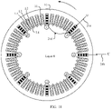
- FIG. 2 is a schematic diagram of a cross section of the six-phase motor 100 according to this application.
- FIG. 3 is a schematic diagram of an enlarged part in FIG. 2 .
- the six-phase flat wire wave winding structure includes a six-phase flat wire wave winding 20, and the six-phase flat wire wave winding 20 includes a U-phase wave winding 21, a V-phase wave winding 22, a W-phase wave winding 23, an A-phase wave winding 24, a B-phase wave winding 25, and a C-phase wave winding 26.
- the six-phase flat wire wave winding 20 includes two symmetrical three-phase wave windings.
- the U-phase wave winding 21, the V-phase wave winding 22, and the W-phase wave winding 23 may be one three-phase wave winding.
- the A-phase wave winding 24, the B-phase wave winding 25, and the C-phase wave winding 26 may be the other three-phase wave winding.
- the two three-phase wave windings are disposed symmetrically, and a difference between electrical angles of the two three-phase wave windings is 30 degrees. To be specific, phases of the two three-phase wave windings are different.
- Some existing six-phase motors 100 include two three-phase wave windings that have same phases and that are connected in parallel or in series. However, a motor with this structure is essentially a dual three-phase winding motor, rather than a six-phase winding motor, and harmonic cannot be counteracted. However, the six-phase motor 100 provided in this embodiment of this application includes two three-phase wave windings with different phases, and harmonic can be counteracted.
- the six-phase motor 100 in FIG. 2 in this embodiment of this application is described by using an 8-pole motor as an example. That is, the six-phase motor 100 shown in FIG. 2 has eight poles and four pole pairs, and each pole pair includes an N pole and an S pole. Therefore, as shown in FIG. 2 and FIG. 3 , the six-phase flat wire wave winding 20 in each pole is sequentially wound in the stator slot 11.
- each stator slot 11 has 2M layers of an in-phase wave winding, and the wave windings in the stator slots 11 have a same quantity of layers.
- M 2M layers of an in-phase wave winding
- the wave windings in the stator slots 11 have a same quantity of layers.
- M 2M layers of an in-phase wave winding
- M 2M layers of an in-phase wave winding
- each stator slot 11 has four layers of in-phase wave windings
- each of the stator slots 11 has four layers of the wave winding.
- each stator slot 11 has an even number of layers.
- one of the stator slots 11 has four layers of a U-phase wave winding 21.
- the four layers of the U-phase wave winding 21 are respectively an L1 layer, an L2 layer, an L3 layer, and an L4 layer, and the wave winding in the L1 layer, the L2 layer, the L3 layer, and the L4 layer is the U-phase wave winding 21. Therefore, as shown in FIG. 5 , an insulation layer does not need to be disposed between two adjacent layers of the wave winding in the same stator slot 11.
- Each phase of wave winding has a wire-in end and a wire-out end.
- the U-phase wave winding 21 has a wire-in end 21a (namely, U+) and a wire-out end 21b (namely, U-);
- the V-phase wave winding 22 has a wire-in end 22a (namely, V+) and a wire-out end 22b (namely, V-);
- the W-phase wave winding 23 has a wire-in end 23a (namely, W+) and a wire-out end 23b (namely, W-);
- the A-phase wave winding 24 has a wire-in end 24a (namely, A+) and a wire-out end 24b (namely, A-);
- the B-phase wave winding 25 has a wire-in end 25a (namely, B+) and a wire-out end 25b (namely, B-);
- the C-phase wave winding 26 has a wire-in end 26a (namely, C+) and a wire-out end 26
- the wire of each phase of wave winding forms an effective edge 20b and two end portions of the six-phase flat wire wave winding 20.
- the six-phase flat wire wave winding 20 includes the effective edge 20b and the two end portions.
- the two end portions are respectively a first end portion 20a and a second end portion 20c.
- the effective edge 20b is located in the stator slot 11.
- the first end portion 20a and the second end portion 20c are located outside the stator slot 11 and are respectively located on two ends of the effective edge 20b.
- the U-phase wire 21c includes a U-phase effective edge 212c and two U-phase end portions.
- the two U-phase end portions are respectively a first U-phase end portion 211c and a second U-phase end portion 213c.
- the U-phase effective edge 212c is located in each stator slot 11 corresponding to the U-phase wave winding 21.
- the first U-phase end portion 211c and the second U-phase end portion 213c are respectively located on two ends of the U-phase effective edge 212c.
- the wire-in end and the wire-out end of each phase of wave winding are both located at a bottom of the stator slot 11.
- the wave winding in the L 1 layer in the stator slot 11 is located at the bottom of the stator slot 11 (as shown in FIG. 5 ). Therefore, the wire-in end of the wave winding is led in from the L1 layer in one of the stator slots 11, and the wire-out end of the wave winding is led out from the L1 layer of another stator slot 11.
- the wire-in end and the wire-out end of each phase of wave winding are both located at an opening of the stator slot 11.
- the wave winding in the L4 layer in the stator slot 11 is located at the opening of the stator slot 11 (as shown in FIG. 5 ). Therefore, the wire-in end of the wave winding is led in from the L4 layer in one of the stator slots 11, and the wire-out end of the wave winding is led out from the L4 layer of another stator slot 11.
- the wire-in end 21a of the U-phase wave winding 21 is led in from the L1 layer of the seventh stator slot 11, and the wire-out end 21b of the U-phase wave winding 21 is led out from the L1 layer of the 13th stator slot 11.
- the wire-in end 21a and the wire-out end 21b of the U-phase wave winding 21 are both located at the bottom of the stator slot 11.
- the wire-in end and the wire-out end of each phase of wave winding are both located at the opening or the bottom of the stator slot 11, to facilitate connection of an end portion of a led-out wire.
- each phase of wave winding includes a branch windings.
- each phase of wave winding may include one branch winding, or each phase of wave winding may include two or more branch windings.
- the two or more branch windings in each phase of branch winding are connected in parallel.
- Each phase of branch winding is wound in Pq stator slots 11. Therefore, for the six-phase flat wire wave winding, a total quantity of the stator slots 11 is 6Pq.
- P is a quantity of poles of the motor.
- a value of P is specifically selected based on an actual requirement. For example, P may be 8, 6, or 4.
- q is a quantity of slots of each phase of wave winding in each pole, and q and a may be positive integers such as 1, 2, or 3.
- each phase of branch winding is wound in eight stator slots 11, and the total quantity of the stator slots 11 is 48.
- the 48 stator slots 11 are separately numbered.
- the 48 stator slots 11 are numbered by using numbers 1 to 48.
- the eight stator slots 11 in which the U-phase wave winding 21 is wound are respectively the first slot, the seventh slot, the 13th slot, the 19th slot, the 25th slot, the 31st slot, the 37th slot, and the 43rd slot.
- the wire-in end 21a of the U-phase wave winding 21 is led in from the L1 layer of the seventh slot, and after winding in four layers in the foregoing eight slots, the wire-out end 21b of the U-phase wave winding 21 is led out from the L1 layer of the 13th slot.
- the six-phase motor 100 is an eight-pole motor (that is, a quantity P of poles of the motor is 8), and a quantity q of slots of each phase in each pole is 1, that is, in each magnetic pole, each phase of wave winding is wound in one stator slot 11.
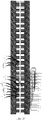
- the 48 stator slots 11 are respectively represented by S1 to S48 in Table 1, or represented by numbers 1 to 48 in FIG. 6 .
- a quantity of layers of each phase of wave winding in the stator slot 11 is 2M.
- X i is defined as an ith layer of an Xth slot
- a winding manner of any phase of wave winding is: X 3 ⁇ X + 6 ⁇ 1 4 ⁇ X + 6 ⁇ 2 3 ⁇ X + 6 ⁇ 3 4 ⁇ ⁇ X + 6 ⁇ P ⁇ 1 4 ⁇ ...
- each phase of wave winding in each pole is wound in 2M layers in a same stator slot 11
- the wave winding is first wound in odd-numbered layers in the same stator slot 11, then wound in even-numbered layers in the same stator slot, and quantities of layers in which each phase of wave winding is wound in stator slots of two adjacent poles are different. For example, after winding is performed in the L 1 layer in the Xth slot, winding is performed in the L2 layer in an (X+6)th slot, and then winding is performed in the L1 layer in an (X+12)th slot.
- Each stator slot 11 has four layers of the wave winding.
- the L1 layer of the wave winding is located at the bottom of the stator slot 11, the L4 layer is close to the opening of the stator slot 11, the L1 layer is the first layer, L2 is the second layer, L3 is the third layer, and L4 is the fourth layer.
- the six-phase flat wire wave winding 20 includes the U-phase wave winding, the V-phase wave winding, the W-phase wave winding, the A-phase wave winding, the B-phase wave winding, and the C-phase wave winding, where"+" in Table 1 represents current inflow into a conductor, and "-" represents current outflow from a conductor.
- a winding manner of any phase of wave winding is: X 1 ⁇ X + 6 ⁇ 1 2 ⁇ X + 6 ⁇ 2 1 ⁇ X + 6 ⁇ 3 2 ⁇ ⁇ X + 6 ⁇ P ⁇ 1 2 ⁇ X 3 ⁇ X + 6 ⁇ 1 4 ⁇ X + 6 ⁇ 2 3 ⁇ X + 6 ⁇ 3 4 ⁇ ⁇ X + 6 ⁇ P ⁇ 1 4 ⁇ X 4 ⁇ X + 6 ⁇ P ⁇ 1 3 ⁇ X + 6 ⁇ P ⁇ 2 4 ⁇ X + 6 ⁇ P ⁇ 3 3 ⁇ X + 6 ⁇ 1 3 ⁇ X 2 ⁇ X + 6 ⁇ P ⁇ 3 3 ⁇ X + 6 ⁇ P ⁇ 1 3 ⁇ X 2 ⁇ X + 6 ⁇ P ⁇ 1 1 1 ⁇ X + 6 ⁇ P ⁇ 2 2 ⁇ X + 6 ⁇ P ⁇ 3 1 ⁇ X + 6 ⁇ P ⁇ 1
- winding when any phase of wave winding is first wound in one layer in corresponding P slots, winding may be: X 1 ⁇ X + 6 ⁇ 1 2 ⁇ X + 6 ⁇ 2 1 ⁇ X + 6 ⁇ 3 2 ⁇ ⁇ X + 6 ⁇ P ⁇ 1 2
- winding may be: X 3 ⁇ X + 6 ⁇ 1 4 ⁇ X + 6 ⁇ 2 3 ⁇ X + 6 ⁇ 3 4 ⁇ ⁇ X + 6 ⁇ P ⁇ 1 4
- winding may be: X 4 ⁇ X + 6 ⁇ P ⁇ 1 3 ⁇ X + 6 ⁇ P ⁇ 2 4 ⁇ X + 6 ⁇ P ⁇ 3 3 ⁇ ⁇ X + 6 ⁇ 1 3
- winding may be: X 2 ⁇ X + 6 ⁇ P ⁇ 1 1 ⁇ X + 6 ⁇ P ⁇ 2 2 ⁇ X + 6 ⁇ P ⁇ 3 1 ⁇ ⁇ X + 6 ⁇ 1 1
- any phase of wave winding completes winding in four layers in the stator slots 11.
- each phase of wave winding is wound in eight slots, and a winding manner of any phase of wave winding is: X 1 ⁇ X + 6 2 ⁇ X + 12 1 ⁇ X + 18 2 ⁇ X + 24 1 ⁇ X + 30 2 ⁇ X + 36 1 ⁇ X + 42 2 ⁇ X 3 ⁇ X + 6 4 ⁇ X + 12 3 ⁇ X + 18 4 ⁇ X + 24 3 ⁇ X + 30 4 ⁇ X + 36 3 ⁇ X + 42 4 ⁇ X 4 ⁇ X + 42 3 ⁇ X + 36 4 ⁇ X + 30 3 ⁇ X + 24 4 ⁇ X + 18 3 ⁇ X + 12 4 ⁇ X + 6 3 ⁇ X 2 ⁇ X + 42 1 ⁇ X + 36 2 ⁇ X + 30 1 ⁇ X + 24 2 ⁇ X + 18 1 ⁇ X + 12 2 ⁇ X + 30 1 ⁇ X + 24 2 ⁇ X + 18
- winding is: the L3 layer in the first slot, the L4 layer in the seventh slot, the L3 layer in the 13th slot, the L4 layer in the 19th slot, the L3 layer in the 25th slot, the L4 layer in the 31st slot, the L3 layer in the 37th slot, and the L4 layer in the 43rd slot.
- winding is: the L4 layer in the first slot, the L3 layer in the 43rd slot, the L4 layer in the 37th slot, the L3 layer in the 31st slot, the L4 layer in the 25th slot, the L3 layer in the 19th slot, the L4 layer in the 13th slot, and the L3 layer in the seventh slot.
- winding is: the L2 layer in the first slot, the L1 layer in the 43rd slot, the L2 layer in the 37th slot, the L1 layer in the 31st slot, the L2 layer in the 25th slot, the L1 layer in the 19th slot, the L2 layer in the 13th slot, and the L1 layer in the seventh slot.
- the U-phase wave winding 21 may be wound starting from the seventh slot, and the eight stator slots 11 in which the U-phase wave winding 21 is wound are respectively: the seventh slot, the 13th slot, the 19th slot, the 25th slot, the 31st slot, the 37th slot, the 43rd slot, and the 49th slot. In this embodiment of this application, because there are 48 stator slots 11, the 49th slot is the first slot.
- winding may be performed along a clockwise arrow direction in FIG. 8 , namely, in ascending order of slot numbers.
- FIG. 8 for a winding sequence: the L1 layer of the seventh slot, the L2 layer of the 13th slot, the L1 layer of the 19th slot, the L1 layer of the 25th slot, the L1 layer of the 31st slot, the L1 layer of the 37th slot, the L1 layer of the 43rd slot, and the L2 layer of the first slot.
- winding continues to be performed along the clockwise arrow direction, and the winding sequence is: the L3 layer of the seventh slot, the L4 layer of the 13th slot, the L3 layer of the 19th slot, the L4 layer of the 25th slot, the L3 layer of the 31st slot, the L4 layer of the 37th slot, the L3 layer of the 43rd slot, and the L4 layer of the first slot.
- winding is performed along an anticlockwise arrow direction, namely, in descending order of slot numbers, and the winding sequence is: the L4 layer of the seventh slot, the L3 layer of the first slot, the L4 layer of the 43rd slot, the L3 layer of the 37th slot, the L4 layer of the 31st slot, the L3 layer of the 25th slot, the L4 layer of the 19th slot, and the L3 layer of the 13th slot.
- the wire-in end 21a and the wire-out end 21b of the U-phase wave winding 21 are both located at the bottom of the stator slot 11, to be specific, are led in and led out both from the L1 layer, to facilitate connection of an end portion of a led-out wire.
- each phase of wave winding has a jumper.
- One end of the jumper is connected to the (2M)th layer of winding in the [X+6 ⁇ (P-1)]th slot, and the other end of the jumper is connected to the (2M)th layer of winding in the Xth slot.
- the U-phase wave winding 21 has a jumper 21d, and two ends of the jumper 21d are respectively connected to the L4 layer of the seventh slot and the L4 layer of the first slot.
- a span of the jumper of each phase of wave winding is y, and y is 6q.
- a quantity q of the slots of each phase of wave winding in each pole is 1. Therefore, as shown in FIG. 7 , the span y of the jumper 21d is 6.
- the wire-in ends and the wire-out ends of the phases of wave windings are close to each other, and the wire-out ends of the phases of wave windings have a same twist angle (namely, a bending angle).
- the wire-out ends of the phases of wave windings can be directly led out in parallel, or led out by using a copper busbar (busbar).
- busbar copper busbar
- the wire-in ends and the wire-out ends of the six-phase flat wire wave winding 20 may use a star connection manner in which a neutral point is shared, as shown in FIG. 12 , or may use a star connection manner in which a neutral point is not shared, as shown in FIG. 13 , or may use a triangular connection manner in FIG. 14 .
- wiring of the phases of the wave windings is flexible, and may be selected based on a design requirement.
- a winding manner of any phase of wave winding is: X 1 ⁇ X + 6 ⁇ 1 2 ⁇ X + 6 ⁇ 2 1 ⁇ X + 6 ⁇ 3 2 ... ⁇ X + 6 ⁇ P ⁇ 1 2 ⁇ X 3 ⁇ X + 6 ⁇ 1 4 ⁇ X + 6 ⁇ 2 3 ⁇ X + 6 ⁇ 3 4 ... ⁇ X + 6 ⁇ P ⁇ 1 4 ⁇ X 5 ⁇ X + 6 ⁇ 1 6 ⁇ X + 6 ⁇ 2 5 ⁇ X + 6 ⁇ 3 6 ... ⁇ X + 6 ⁇ P ⁇ 1 6 ⁇ X 6 ⁇ X + 6 ⁇ P ⁇ 1 5 ⁇ X + 6 ⁇ P ⁇ 2 6 ⁇ X + 6 ⁇ P ⁇ 3 5 ... ⁇ X + 6 ⁇ 1 5 ⁇ X + 6 ⁇ P ⁇ 2 6 ⁇ X + 6 ⁇ P ⁇ 3 5 ... ⁇ X + 6 ⁇
- a winding manner of any phase of wave winding is: X 1 ⁇ X + 6 ⁇ 1 2 ⁇ X + 6 ⁇ 2 1 ⁇ X + 6 ⁇ 3 2 ⁇ X + 6 ⁇ 4 1 ⁇ X + 6 ⁇ 5 2 ⁇ X + 6 ⁇ 6 1 ⁇ X + 6 ⁇ 7 2 ⁇ X 3 ⁇ X + 6 ⁇ 1 4 ⁇ X + 6 ⁇ 2 3 ⁇ X + 6 ⁇ 3 4 ⁇ X + 6 ⁇ 4 3 ⁇ X + 6 ⁇ 5 4 ⁇ X + 6 ⁇ 6 3 ⁇ X + 6 ⁇ 7 4 ⁇ X 5 ⁇ X + 6 ⁇ 1 6 ⁇ X + 6 ⁇ 2 5 ⁇ X + 6 ⁇ 3 6 ⁇ X + 6 ⁇ 4 5 ⁇ X + 6 ⁇ 5 6 ⁇ X + 6 ⁇ 6 5 ⁇ X + 6 ⁇ 6 5 ⁇ X + 6 ⁇ 7 6 ⁇ X 6 ⁇
- quantities of winding layers of each stator slot 11 include but are not limited to four and six, or may be two, eight, or the like. Refer to the winding manner of four layers and six layers for the winding manner.
- each phase of wave winding has conductors in all layers of a same stator slot, and the wave windings are uniformly and symmetrically distributed. Potentials of branches are balanced, and there is no loop current. Conductors in different layers of a same slot are in-phase, and do not need to be isolated by insulating paper. This helps improve a slot fill factor and reduce costs. In addition, problems that a flat wire winding process is highly difficult and manufacturing costs are high due to an increase in a quantity of phases of the six-phase motor are effectively resolved.
- the 72 stator slots 11 are respectively represented by S1 to S72 in Table 2, or represented by numbers 1 to 72 in FIG. 15 .
- a quantity of layers of each phase of wave winding in the stator slot 11 is 2M.
- X i is defined as an ith layer of an Xth slot, and a winding manner of any phase of wave winding is: X 1 ⁇ X + 12 ⁇ 1 2 ⁇ X + 12 ⁇ 2 1 ⁇ X + 12 ⁇ 3 2 ... ⁇ X + 12 ⁇ P ⁇ 1 2 ⁇ X 3 ⁇ X + 12 ⁇ 1 4 ⁇ X + 12 ⁇ 2 3 ⁇ X + 12 ⁇ 3 4 ... ⁇ X + 12 ⁇ P ⁇ 1 4 ⁇ ... X 2 M ⁇ 1 ⁇ X + 12 ⁇ 1 2 M ⁇ X + 12 ⁇ 2 2 M ⁇ 1 ⁇ X + 12 ⁇ 3 2 M ... ⁇ X + 12 ⁇ P ⁇ 1 2 M ⁇ X 2 M ⁇ 1 ⁇ X + 12 ⁇ 3 2 M ... ⁇ X + 12 ⁇ P ⁇ 1 2 M
- each phase of wave winding first forms a first coil in one of the stator slots 11 in each pole based on the winding manner in the foregoing Embodiment 1, and then, each phase of wave winding forms a second coil in the other stator slot 11 in each pole based on the winding manner in Embodiment 1.
- the first coil is connected in series to the second coil.
- a difference between phases of the first coil and the second coil is 30/q degrees.
- each stator slot 11 has four layers of the wave winding.
- a winding manner in which any phase of wave winding is wound in four layers in the stator slot 11 is: X 1 ⁇ X + 12 ⁇ 1 2 ⁇ X + 12 ⁇ 2 1 ⁇ X + 12 ⁇ 3 2 ... ⁇ X + 12 ⁇ P ⁇ 1 2 ⁇ X 3 ⁇ X + 12 ⁇ 1 4 ⁇ X + 12 ⁇ 2 3 ⁇ X + 12 ⁇ 3 4 ... ⁇ X + 12 ⁇ P ⁇ 1 4 ⁇ X 4 ⁇ X + 12 ⁇ P ⁇ 1 3 ⁇ X + 12 ⁇ P ⁇ 2 4 ⁇ X + 12 ⁇ P ⁇ 3 3 ... ⁇ X + 12 ⁇ 1 3 ⁇ X 2 ⁇ X + 12 ⁇ P ⁇ 1 1 1 ⁇ X + 12 ⁇ P ⁇ 2 2 ⁇ X + 12 ⁇ P ⁇ 3 1 ... ⁇ X + 12 ⁇ 1 3 ⁇
- each phase of wave winding in each pole is wound in two adjacent stator slots 11, and a winding manner in which any phase of wave winding is wound in four layers is: X 1 ⁇ X + 12 2 ⁇ X + 24 1 ⁇ X + 36 2 ⁇ X + 48 1 ⁇ X + 60 2 ⁇ X 3 ⁇ X + 12 4 ⁇ X + 24 3 ⁇ X + 36 4 ⁇ X + 48 3 ⁇ X + 60 4 ⁇ X 4 ⁇ X + 60 3 ⁇ X + 48 4 ⁇ X + 36 3 ⁇ X + 24 4 ⁇ X + 12 3 ⁇ X 2 ⁇ X + 60 1 ⁇ X + 48 2 ⁇ X + 36 1 ⁇ X + 24 2 ⁇ X + 36 1 ⁇ X + 24 2 ⁇ X + 12 1 ⁇ X + 1 1 ⁇ X + 1 + 12 2 ⁇ X + 1 + 24 1 ⁇ X + 1 + 36 2 ⁇ X + 1 + 36 2
- the B-phase wave winding 25 when the B-phase wave winding 25 is wound, X is 11, that is, the wire-in end 25a of the B-phase wave winding 25 starts from the L1 layer of the 11th slot, and the B-phase wave winding 25 is wound in two adjacent layers in each pole.
- the B-phase wave winding 25 is separately wound in: the 11th slot and the 12th slot, the 23rd slot and the 24th slot, the 35th slot and the 36th slot, the 47th slot and the 48th slot, the 59th slot and the 60th slot, and the 71st slot and the 72nd slot.
- the B-phase wave winding 25 is wound in two layers in one of the stator slots 11 of each pole, and then, along an opposite direction, is wound in last two layers in the stator slot 11, to form the first coil. Then, the B-phase wave winding 25 is wound starting from the L1 layer of the 12th slot, that is, the B-phase wave winding 25 is first wound in two layers in the other adjacent stator slot 11 of each pole, and then, along an opposite direction, is wound in last two layers in the adjacent stator slot 11, to form the second coil. The first coil is connected in series to the second coil to form the B-phase wave winding 25 shown in FIG. 16 .
- Each phase of wave winding has a first jumper 251d, a second jumper 252d, and a third jumper 253d. That is, each phase of wave winding has three jumpers. Two ends of the first jumper 251d are respectively connected to a (2M)th layer of an [X+12 ⁇ (P-1)]th slot and a (2M)th layer of an Xth slot, two ends of the second jumper 252d are respectively connected to the first layer of an (X+12)th slot and the first layer of an (X+1)th slot, and two ends of the third jumper 253d are respectively connected to an (2M)th layer of an [X+1+12 ⁇ (P-1)]th slot and a (2M)th layer of the (X+1)th slot.
- the B-phase wave winding 25 has the first jumper 251d, the second jumper 252d, and the third jumper 253d.
- the two ends of the first jumper 251d are respectively connected to the L4 layer of the 71st slot and the L4 layer of the 11th slot
- the two ends of the second jumper 252d are respectively connected to the L1 layer of the 23rd slot and the L1 layer of the 12th slot
- the two ends of the third jumper 253d are respectively connected to the L4 layer of the 72nd slot and the L4 layer of the 12th slot.
- a span of the first jumper 251d is y
- a span of the second jumper 252d is y-1
- the wire-in ends and the wire-out ends of the phases of wave windings are close to each other, and the wire-out ends of the phases of wave windings have a same twist angle (namely, a bending angle).
- the wire-out ends of the phases of wave windings can be directly led out in parallel, or led out by using a copper busbar (busbar).
- busbar copper busbar
- the wire includes an effective edge 212c and two B-phase end portions.
- the two B-phase end portions are respectively a first B-phase end portion 211c and a second B-phase end portion 213c.
- the effective edge 212c is located in the stator slots 11 corresponding to the B-phase wave winding 25 (for example, the 11th slot and the 12th slot, the 23rd slot and the 24th slot, the 35th slot and the 36th slot, the 47th slot and the 48th slot, the 59th slot and the 60th slot, and the 71st slot and the 72nd slot).
- the first B-phase end portion 211c and the second B-phase end portion 213c are separately located outside the stator slots 11, and the first B-phase end portion 211c and the second B-phase portion 213c are respectively located on two ends of the effective edge 212c.
- Each phase of wave winding is wound in 2M layers in one of the stator slots 11 of each pole, to form the first coil, and each phase of wave winding is wound in 2M layers in the other stator slot 11 of each pole, to form the second coil.
- the first coil is connected in series to the second coil by using the second jumper 252d.
- the B-phase wave winding 25 is separately wound in four layers in the 11th slot, the 23rd slot, the 35th slot, the 47th slot, the 59th slot, and the 71st slot, to form the first coil
- the B-phase wave winding 25 is separately wound in four layers in the 12th slot, the 24th slot, the 36th slot, the 48th slot, the 60th slot, and the 72nd slot, to form the second coil.
- the winding manner of the second coil is the same as that of the first coil.
- the second coil performs overall translation by one stator slot 11, and the first coil is connected in series to the second coil by using the second jumper 252d.
- a difference between phases of the first coil and the second coil is 30/q degrees.
- winding is performed in six layers in each stator slot, which may be respectively an L1 layer, an L2 layer, an L3 layer, an L4 layer, an L5 layer (not shown), and an L6 layer (not shown), and a winding manner of any phase of wave winding is: X 1 ⁇ X + 12 ⁇ 1 2 ⁇ X + 12 ⁇ 2 1 ⁇ X + 12 ⁇ 3 2 ... ⁇ X + 12 ⁇ P ⁇ 1 2 ⁇ X 3 ⁇ X + 12 ⁇ 1 4 ⁇ X + 12 ⁇ 2 3 ⁇ X + 12 ⁇ 3 4 ... ⁇ X + 12 ⁇ P ⁇ 1 4 ⁇ X 5 ⁇ X + 12 ⁇ 1 6 ⁇ X + 12 ⁇ 2 5 ⁇ X + 12 ⁇ 3 6 ... ⁇ X + 12 ⁇ P ⁇ 1 6 ⁇ X 6 ⁇ X + 12 ⁇ P ⁇ 1 5 ⁇ X + 12 ⁇ P ⁇ 1 5 ⁇ X + 12
- a winding manner of any phase of wave winding is: X 1 ⁇ X + 12 ⁇ 1 2 ⁇ X + 12 ⁇ 2 1 ⁇ X + 12 ⁇ 3 2 ⁇ X + 12 ⁇ 4 1 ⁇ X + 12 ⁇ 5 2 ⁇ X 3 ⁇ X + 12 ⁇ 1 4 ⁇ X + 12 ⁇ 2 3 ⁇ X + 12 ⁇ 3 4 ⁇ X + 12 ⁇ 4 3 ⁇ X + 12 ⁇ 5 4 ⁇ X 5 ⁇ X + 12 ⁇ 1 6 ⁇ X + 12 ⁇ 2 5 ⁇ X + 12 ⁇ 3 6 ⁇ X + 12 ⁇ 4 5 ⁇ X + 12 ⁇ 5 6 ⁇ X + 12 ⁇ 2 5 ⁇ X + 12 ⁇ 3 6 ⁇ X + 12 ⁇ 4 5 ⁇ X + 12 ⁇ 5 6 ⁇ X 6 ⁇ X + 12 ⁇ 5 5 ⁇ X + 12 ⁇ 4 6 ⁇ X + 12 ⁇ 3 5 ⁇
- Each phase of wave winding is wound in six layers in one of the stator slots 11 of each pole to form the first coil, and each phase of wave winding is wound in six layers in the other adjacent stator slot 11 of each pole to form the second coil.
- the first coil is connected in series to the second coil by using the second jumper 252d.
- quantities of winding layers of each stator slot 11 include but are not limited to four and six, or may be two, eight, or the like. Refer to the winding manner of four layers and six layers for the winding manner.
- the U-phase wave winding 21 includes a first U-phase branch winding 211 (namely, U1) and a second U-phase branch winding 212 (namely, U2)
- the V-phase wave winding 22 includes a first V-phase branch winding 221 (namely, VI) and a second V-phase branch winding 222 (namely, V2)
- the W-phase wave winding 23 includes a first W-phase branch winding 231 (namely, W1) and a second W-phase branch winding 232 (namely, W2)
- the A-phase wave winding 24 includes a first A-phase branch winding 241 (namely, A1) and a second A-phase branch winding 242 (namely, A2)
- the B-phase wave winding 25 includes a first B-phase branch winding 251 (namely, B1) and a second B-phase branch winding 252 (namely, B2)
- the C-phase wave winding 26 includes a first C-phase branch winding 261 (namely, C1) and a second C-phase branch wind
- Each of the first branch winding and the second branch winding of each phase in each pole has two slots.
- each stator slot 11 has the first branch winding and the second branch winding that are in-phase and that have a same quantity of layers.
- the first branch winding and the second branch winding are alternately arranged in a same stator slot 11.
- the two branch windings in each phase of each pole jointly multiplex two stator slots 11.
- a quantity of layers of the first branch winding and a quantity of layers of the second branch winding may both be 2M.
- the other two layers of the first branch winding are located in the L2 layer and the L4 layer of the adjacent stator slot 11, and the L1 layer and the L3 layer of the adjacent stator slot 11 may be the other two layers in which the second branch winding is wound.
- the four layers of the first branch winding are uniformly distributed in two adjacent stator slots 11.
- each stator slot 11 has two layers of the first branch winding and two layers of the second branch winding, and the two layers of the first branch winding and the two layers of the second branch winding are alternately arranged.
- first branch winding and the second branch winding are alternately arranged in a same stator slot 11 specifically means that, the L1 layer of the stator slot 11 may be the first branch winding, the L2 layer of the stator slot 11 may be the second branch winding, the L3 layer of the stator slot 11 may be the first branch winding, and the L4 layer of the stator slot 11 may be the second branch winding.
- two adjacent layers in a same stator slot 11 are two different branch windings of a same phase of wave winding.
- the first branch winding and the second branch winding are alternately arranged in a same stator slot 11.
- two parallel branch windings of each phase of wave winding are uniformly and symmetrically distributed in the layers of the same stator slot 11, and potentials of the branch windings of each phase of wave winding are balanced, to avoid generation of a loop current, and reduce losses, thereby improving efficiency of the motor.
- a winding manner of a first branch winding in any phase of wave winding is: X 1 ⁇ X + 12 ⁇ 1 2 ⁇ X + 12 ⁇ 2 1 ⁇ X + 12 ⁇ 3 2 ... ⁇ X + 12 ⁇ P ⁇ 1 2 ⁇ X 3 ⁇ X + 12 ⁇ 1 4 ⁇ X + 12 ⁇ 2 3 ⁇ X + 12 ⁇ 3 4 ... ⁇ X + 12 ⁇ P ⁇ 1 4 ⁇ ... X 2 M ⁇ 1 ⁇ X + 12 ⁇ 1 2 M ⁇ X + 12 ⁇ 2 2 M ⁇ 1 ⁇ X + 12 ⁇ 3 2 M ... ⁇ X + 12 ⁇ P ⁇ 1 2 M ⁇ X + 1 2 M ⁇ X + 1 + 12 ⁇ P ⁇ 2 M ⁇ X + 1 + 12 ⁇ P ⁇ 1 2 M ⁇ 1 ⁇ X + 1 + 12 ⁇ P ⁇ 2 2 M ⁇ 1 + 12 ⁇ P ⁇ 2 M ⁇
- X is less than 13
- the first branch winding of each phase of wave winding is wound in M layers in one of the stator slots of each pole to form a third coil
- the first branch winding of each phase of wave winding is wound in M layers in the other adjacent stator slot of each pole to form a fourth coil
- the third coil is connected in series to the fourth coil
- a difference between phases of the third coil and the fourth coil is 30/q degrees.
- a winding manner of a second branch winding in any phase of wave winding is: X + 1 1 ⁇ X + 1 + 12 ⁇ 1 2 ⁇ X + 1 + 12 ⁇ 2 1 ⁇ X + 1 + 12 ⁇ 3 2 ... ⁇ X + 1 + 12 ⁇ P ⁇ 1 2 ⁇ X + 1 3 ⁇ X + 1 + 12 ⁇ 1 4 ⁇ X + 1 + 12 ⁇ 2 3 ⁇ X + 1 + 12 ⁇ 3 4 ... ⁇ X + 1 + 12 ⁇ P ⁇ 1 4 ⁇ ... X + 1 2 M ⁇ 1 ⁇ X + 1 + 12 ⁇ 1 2 M ⁇ X + 12 ⁇ 2 2 M ⁇ 1 ⁇ X + 12 ⁇ 3 2 M ... ⁇ X + 12 ⁇ P ⁇ 1 2 M ⁇ X 2 M ⁇ 1 ⁇ X + 12 ⁇ 3 2 M ... ⁇ X + 12 ⁇ P ⁇ 1 2 M ⁇ X 2 M ⁇ X + 12
- the second branch winding of each phase of wave winding is wound in M layers in one of the stator slots of each pole to form a fifth coil
- the second branch winding of each phase of wave winding is wound in M layers in the other adjacent stator slot of each pole to form a sixth coil
- the fifth coil is connected in series to the sixth coil, and a difference between phases of the sixth coil and the fifth coil is 30/q degrees.
- each phase of wave winding is wound in four layers in the stator slot 11, and the first branch winding in any phase of wave winding may be wound starting from an Xth slot (X is less than 13), and a winding manner is as follows: X 1 ⁇ X + 12 ⁇ 1 2 ⁇ X + 12 ⁇ 2 1 ⁇ X + 12 ⁇ 3 2 ⁇ ⁇ X + 12 ⁇ P ⁇ 1 2 ⁇ X 3 ⁇ X + 12 ⁇ 1 4 ⁇ X + 12 ⁇ 2 3 ⁇ X + 12 ⁇ 3 4 ⁇ ⁇ X + 12 ⁇ P ⁇ 1 4 ⁇ X + 1 4 ⁇ X + 1 + 12 ⁇ P ⁇ 1 4 ⁇ X + 1 4 ⁇ X + 1 + 12 ⁇ P ⁇ 1 3 ⁇ X + 1 + 12 ⁇ P ⁇ 2 4 ⁇ X + 1 + 12 ⁇ P ⁇ 3 3 ⁇ X + 1 + 12 ⁇ P ⁇ 3 3 ⁇ X + 1 + 12 ⁇
- the first branch winding is first wound in two layers in one of the stator slots 11 of each pole, to form the third coil, and is then wound in other two layers in the other stator slot 11 of each pole, to form the fourth coil.
- the third coil is connected in series to the fourth coil.
- a difference between phases of the third coil and the fourth coil is 30/q degrees.
- the second branch winding in any phase of wave winding may be wound starting from an (X+1)th slot (X is less than 13), and a winding manner is: X + 1 1 ⁇ X + 1 + 12 ⁇ 1 2 ⁇ X + 1 + 12 ⁇ 2 1 ⁇ X + 1 + 12 ⁇ 3 2 ⁇ ⁇ X + 1 + 12 ⁇ P ⁇ 1 2 ⁇ X + 1 3 ⁇ X + 1 + 12 ⁇ 1 4 ⁇ X + 1 + 12 ⁇ 2 3 ⁇ X + 1 + 12 ⁇ 3 4 ⁇ ⁇ X + 1 + 12 ⁇ P ⁇ 1 4 ⁇ X 4 ⁇ X + 12 ⁇ P ⁇ 1 3 ⁇ X + 12 ⁇ P ⁇ 2 4 ⁇ X + 12 ⁇ P ⁇ 3 3 ⁇ X + 12 ⁇ 1 3 ⁇ X 2 ⁇ X + 12 ⁇ P ⁇ 3 3 ⁇ X + 12 ⁇ P ⁇ 1 1 3 ⁇ X 2 ⁇ X + 12
- the second branch winding is first wound in two layers in one of the stator slots 11 of each pole, to form the fifth coil, and is then wound in other two layers in the other stator slot 11 of each pole, to form the sixth coil.
- the fifth coil is connected in series to the sixth coil.
- a difference between phases of the fifth coil and the sixth coil is 30/q degrees.
- the first branch winding of each phase of wave winding has a fourth jumper 254d
- the second branch winding of each phase of wave winding has a fifth jumper 255d.
- Two ends of the fourth jumper 254d are respectively connected to a (2M)th layer of an [X+12 ⁇ (P-1)]th slot and an (2M)th layer of the (X+1)th slot
- two ends of the fifth jumper 255d are respectively connected to a (2M)th layer of an [X+1+12 ⁇ (P-1)]th slot and an (2M)th layer of the Xth slot.
- a span of the fourth jumper 254d is y+1
- a span of the fifth jumper 255d is y-1
- y is 6q.
- Spans between welding ends and non-welding ends of coils of phases of wave windings are equal and are all y. To be specific, the spans between welding ends and non-welding ends of the coils of the phases of wave windings are equal and are all 12.
- the third coil is connected in series to the fourth coil by using the fourth jumper 254d
- the fifth coil is connected in series to the sixth coil by using the fifth jumper 255d.
- the B-phase wave winding 25 includes a first B-phase branch winding 251 and a second B-phase branch winding 252. That is, the B-phase wave winding 25 includes a B1-phase branch winding and a B2-phase branch winding.
- the first B-phase branch winding 251 includes a wire-in end B1+ and a wire-out end B1-.
- the wire 2511c may include two end portions and an effective edge that are located in the stator slots 11 (as shown in FIG. 16 ).
- the wire 2511c may include the foregoing third coil and fourth coil. The third coil is connected in series to the fourth coil by using the fourth jumper 254d.
- the second B-phase branch winding 252 includes a wire-in end B2+ and a wire-out end B2-, and there is a wire 2521c between the wire-in end B2+ and the wire-out end B2-.
- the wire 2521c includes the fifth coil and the sixth coil.
- the fifth coil is connected in series to the sixth coil by using the fifth jumper 255d.
- a span between the wire-in end and the wire-out end of the first branch winding of each phase of wave winding is y+1, and a span between the wire-in end and the wire-out end of the second branch winding of each phase of wave winding is y-1.
- the span between the wire-in end B1+ and the wire-out end B1- of the first B-phase branch winding 251 is y+1
- the first B-phase branch winding 251 of the B-phase wave winding 25 has the fourth jumper 254d.
- the second B-phase branch winding 252 of the B-phase wave winding 25 has the fifth jumper 255d, and two ends of the fifth jumper 255d are respectively connected to the L4 layer of the 72nd slot and the L4 layer of the 11th slot.
- X may alternatively be 13 or 14, for example, the two parallel branches select to be wound respectively starting from the 14th slot and the 13th slot.
- two branch windings of the U -phase wave winding 21 may be wound starting from the first slot and the second slot.
- Two branch windings of the A-phase wave winding 24 may be wound starting from the third slot and the fourth slot.
- Two branch windings of the W-phase wave winding 23 may be wound starting from the fifth slot and the sixth slot.
- Two branch windings of the C-phase wave winding 26 may be wound starting from the seventh slot and the eighth slot.
- Two branch windings of the V-phase wave winding 22 may be wound starting from the ninth slot and the 10th slot.
- the two branch windings of the B-phase wave winding 25 may be wound starting from the 11th slot and the 12th slot.
- Table 3 After winding ends, refer to Table 3 for distribution of four layers of winding in the stator slots 11.
- the first branch winding and the second branch winding are alternately arranged in each stator slot 11, and layers of winding in two adjacent stator slots 11 in which each phase of wave winding in each pole is wound are uniformly and symmetrically distributed, and potentials of the branches are balanced, and there is no loop current.
- winding may alternatively be performed in six layers in each stator slot.
- X is less than 13
- a winding manner is as follows: X 1 ⁇ X + 12 ⁇ 1 2 ⁇ X + 12 ⁇ 2 1 ⁇ X + 12 ⁇ 3 2 ⁇ ⁇ X + 12 ⁇ P ⁇ 1 2 ⁇ X 3 ⁇ X + 12 ⁇ 1 4 ⁇ X + 12 ⁇ 2 3 ⁇ X + 12 ⁇ 3 4 ⁇ ⁇ X + 12 ⁇ P ⁇ 1 4 ⁇ X 5 ⁇ X + 12 ⁇ 1 6 ⁇ X + 12 ⁇ 2 5 ⁇ X + 12 ⁇ 3 6 ⁇ ⁇ X + 12 ⁇ P ⁇ 1 6 ⁇ X + 1 6 ⁇ X + 1 + 12 ⁇ P ⁇ 1 5 ⁇ X + 1 + 1 + 1 + 1 + 12 ⁇ X + 1 + 12 ⁇ P ⁇ 1 5 ⁇ X + 1 + 1 + 1 + 12 ⁇ X + 1 + 12
- the first branch winding is first wound in three layers in one of the stator slots 11 of each pole, to form the third coil, and is then wound in other three layers in the other adjacent stator slot 11 of each pole, to form the fourth coil.
- the third coil is connected in series to the fourth coil.
- a difference between phases of the third coil and the fourth coil is 30/q degrees.
- the second branch winding in any phase of wave winding may be wound starting from the (X+1)th slot (X is less than 13), and the winding manner is: X + 1 1 ⁇ X + 1 + 12 ⁇ 1 2 ⁇ X + 1 + 12 ⁇ 2 1 ⁇ X + 1 + 12 ⁇ 3 2 ⁇ ⁇ X + 1 + 12 ⁇ P ⁇ 1 2 ⁇ X + 1 3 ⁇ X + 1 + 12 ⁇ 1 4 ⁇ X + 1 + 12 ⁇ 2 3 ⁇ X + 1 + 12 ⁇ 3 4 ⁇ ⁇ X + 1 + 12 ⁇ 3 4 ⁇ ⁇ X + 1 + 12 ⁇ P ⁇ 1 4 ⁇ X + 1 5 ⁇ X + 1 + 12 ⁇ 1 6 ⁇ X + 1 + 12 ⁇ 2 5 ⁇ X + 1 + 12 ⁇ 3 6 ⁇ ⁇ X + 1 + 12 ⁇ P ⁇ 1 6 ⁇ X 6 ⁇ X + 12 ⁇ P ⁇ 1 5 ⁇ X + 12
- the second branch winding is first wound in three layers in one of the stator slots 11 of each pole, to form the fifth coil, and is then wound in other three layers in the other adjacent stator slot 11 of each pole, to form the sixth coil.
- the fifth coil is connected in series to the sixth coil.
- a difference between phases of the fifth coil and the sixth coil is 30/q degrees.
- quantities of winding layers of each stator slot 11 include but are not limited to four and six, or may be two, eight, or the like. Refer to the winding manner of four layers and six layers for the winding manner.
- An embodiment of this application further provides a powertrain.
- the powertrain may be applied to an electric vehicle/electric automobile (EV), a pure electric vehicle (PEV/BEV), a hybrid electric vehicle (HEV), a range extended electric vehicle (REEV), a plug-in hybrid electric vehicle (PHEV), or a new energy vehicle (New Energy Vehicle), or may be applied to battery management (Battery Management), a motor & driver (Motor & Driver), a power converter (Power Converter), or another device.
- the powertrain includes at least a speed reducer and the six-phase motor 100 in any one of the foregoing embodiments.
- the motor 100 is connected to the speed reducer (not shown) by using a rotating shaft.
- an output shaft of the six-phase motor 100 is connected to the speed reducer, and the speed reducer may alternatively be integrated with the motor 100 into a reducing motor for use.
- the foregoing six-phase motor 100 is included, and an even number of layers of in-phase wave windings are wound in each stator slot.
- layers of the wave winding in a same stator slot are in-phase.
- insulating paper does not need to be disposed between the in-phase layers of the wave winding for isolation, the insulating paper is prevented from being disposed between the layers of the wave winding in a same stator slot, so that an available space in the stator slot increases.
- a cross-sectional area of the wave winding that can be accommodated in the stator slot increases, to further help increase a slot fill factor.
- each phase of the wave winding has conductors in all layers of a same stator slot, and the six-phase flat wire wave winding structure includes two symmetrical three-phase wave windings, phases of the wave winding are uniformly and symmetrically distributed, and potentials of branches are balanced. There is no loop current, and harmonic is counteracted, so that performance of the powertrain is better.
- the layers of the wave winding in the same stator slot are in-phase, so that problems that a flat wire winding process is highly difficult and manufacturing costs are high due to an increase in the quantity of phases of the six-phase motor are effectively resolved, thereby reducing the manufacturing costs of the powertrain.
- the vehicle may be an electric vehicle/electric automobile (EV), a pure electric vehicle (PEV/BEV), a hybrid electric vehicle (HEV), a range extended electric vehicle (REEV), a plug-in hybrid electric vehicle (PHEV), a new energy vehicle (New Energy Vehicle), or the like.
- EV electric vehicle/electric automobile
- PEV/BEV pure electric vehicle
- HEV hybrid electric vehicle
- REEV range extended electric vehicle
- PHEV plug-in hybrid electric vehicle
- New Energy Vehicle New Energy Vehicle
- the vehicle includes at least wheels, a transmission part, and the six-phase motor 100 in any one of the foregoing embodiments.
- the six-phase motor 100 is connected to the wheels by using the transmission part.
- a rotating shaft of the six-phase motor 100 rotates to output power, and the transmission part transmits power to the wheels, to enable the wheels to rotate.
- the vehicle includes at least the wheels, the transmission part, and the powertrain in the foregoing embodiment.
- An output shaft of the six-phase motor 100 in the powertrain may be connected to a speed reducer.
- the speed reducer may be connected to the transmission part.
- the transmission part is connected to the wheels.
- the foregoing six-phase motor 100 is included, and an even number of layers of in-phase wave windings are wound in each stator slot.
- layers of the wave winding in a same stator slot are in-phase.
- insulating paper does not need to be disposed between the in-phase layers of the wave winding for isolation, the insulating paper is prevented from being disposed between the layers of the wave winding in a same stator slot, so that an available space in the stator slot increases.
- a cross-sectional area of the wave winding that can be accommodated in the stator slot increases, to further help increase a slot fill factor.
- each phase of the wave winding has conductors in all layers of a same stator slot, and the six-phase flat wire wave winding structure includes two symmetrical three-phase wave windings, phases of the wave winding are uniformly and symmetrically distributed, and potentials of branches are balanced. There is no loop current, and harmonic is counteracted, so that performance of the powertrain is better.
- the layers of the wave winding in the same stator slot are in-phase, so that problems that a flat wire winding process is highly difficult and manufacturing costs are high due to an increase in the quantity of phases of the six-phase motor are effectively resolved, thereby reducing the manufacturing costs of the vehicle.
Abstract
Description
- The present invention relates to the field of motor winding technologies, and in particular, to a six-phase flat wire wave winding structure, a six-phase motor, a powertrain, and a vehicle.
- In recent years, miniaturization and high speed have become the main development trend of a motor of a new energy electric vehicle. In comparison with a conventional permanent magnet motor, a winding of a flat wire motor has a characteristic of a high copper fill factor, and the high copper fill factor can greatly increase torque density and power density of the motor. A length of an end portion of the winding of the flat wire motor is relatively short, so that utilization of space of the vehicle can be further improved. A relatively large contact area between wires effectively enhances a heat dissipation capability of the motor. Therefore, the flat wire motor has a good application prospect in new energy electric vehicles.
- In comparison with a three-phase motor, a six-phase motor can counteract specific-order harmonic, reduce torque ripple, and improve NVH performance of the motor. With an increase in a quantity of phases of the motor, a fault tolerance capability of the motor is enhanced and working reliability is higher.
- In the conventional technology, a flat wire wave winding structure uses a connection manner of a short-pitch wave winding, phases of the winding exist in different layers of a stator slot, a wire-out end of each phase is set to a welding end, and a non-wire-out end is a U-shaped wire. However, with an increase in the quantity of phases of the motor, a winding process of the flat wire becomes more difficult. It is difficult to ensure that spans of U -shaped coils are consistent, manufacturing costs correspondingly increase, and multi-layer wiring in a same slot easily causes unbalance between in-phase branches, a loop current is generated, losses are increased, and efficiency of the motor is reduced.
- Embodiments of this application provide a six-phase flat wire wave winding structure, a six-phase motor, a powertrain, and a vehicle. Each phase of wave winding has conductors in all layers of a same stator slot, and the wave windings are uniformly and symmetrically distributed. Potentials of branches are balanced, and there is no loop current. Conductors in different layers of a same slot are in-phase, and do not need to be isolated by insulating paper. This helps improve a slot fill factor and reduce costs. In addition, problems that a flat wire winding process is highly difficult and manufacturing costs are high due to an increase in a quantity of phases of the six-phase motor are effectively resolved.
- An embodiment of this application provides a six-phase flat wire wave winding structure, including a six-phase flat wire wave winding, where each phase of the wave winding includes a wire-in end, a wire-out end, and a wire located between the wire-out end and the wire-in end;
- each phase of the wave winding includes a branch windings, and a quantity of stator slots in which each phase of the branch winding is wound is Pq, a total quantity of the stator slots is 6Pq, P is a quantity of poles of a motor, and q is a quantity of slots of each phase of the wave winding in each pole;
- each of the stator slots has 2M layers of in-phase wave windings, and the wave windings in the stator slots have a same quantity of layers; the wire-in end and the wire-out end of each phase of the wave winding are both located at a bottom or an opening of the stator slot, and a and M are positive integers; and
- the six-phase flat wire wave winding includes two symmetrical three-phase wave windings, and a difference between electrical angles of the two three-phase wave windings is 30 degrees.
- In the six-phase motor provided in this embodiment of this application, an even number of layers of in-phase wave windings are wound in each stator slot. In this way, layers of the wave winding in a same stator slot are in-phase. Because insulating paper does not need to be disposed between the in-phase layers of the wave winding for isolation, the insulating paper is prevented from being disposed between the layers of the wave winding in a same stator slot, so that an available space in the stator slot increases. In this way, a cross-sectional area of the wave winding that can be accommodated in the stator slot increases, to further help increase a slot fill factor. In this way, a magnitude of a current flowing through the wave winding in the stator slot increases, to help increase an output torque of the motor. In addition, the insulating paper is prevented from being disposed in each stator slot, so that costs of the motor are reduced. In addition, each phase of the wave winding has conductors in all layers of a same stator slot, and the six-phase flat wire wave winding structure includes two symmetrical three-phase wave windings, phases of the wave winding are uniformly and symmetrically distributed, and potentials of branches are balanced. There is no loop current, and harmonic is counteracted. In addition, the layers of the wave winding in the same stator slot are in-phase, so that problems that a flat wire winding process is highly difficult and manufacturing costs are high due to an increase in the quantity of phases of the six-phase motor are effectively resolved.
- In a possible implementation, each phase of the wave winding has 2M layers in the stator slot, and when the quantity q of the slots of each phase of the wave winding in each pole is 1, and a=1, a winding manner of any phase of the wave winding is:

- X2M represents a (2M)th layer of an Xth slot, X2M-1 represents a (2M-1)th layer of the Xth slot, X represents the Xth slot in the stator slots, and X is less than 7.
- In a possible implementation, each phase of the wave winding has one jumper, and two ends of the jumper are respectively connected to a (2M)th layer of an [X+6×(P-1)]th slot and the (2M)th layer of the Xth slot.
- In a possible implementation, a span of the jumper of each phase of the wave winding is y; and y is 6q; and
spans between welding ends and non-welding ends of coils of phases of the wave winding are equal and are all y. - In a possible implementation, each phase of the wave winding has 2M layers in the stator slot, and when the quantity q of the slots of each phase of the wave winding in each pole is 2, and a=1, a winding manner of any phase of the wave winding is:

- X2M represents a (2M)th layer of an Xth slot, X2M-1 represents a (2M-1)th layer of the Xth slot, [X+1]2M represents a (2M)th layer of an (X+1)th slot, X represents the Xth slot in the stator slots, and X is less than 13.
- In a possible implementation, each phase of the wave winding has a first jumper, a second jumper, and a third jumper;
- two ends of the first jumper are respectively connected to a (2M)th layer of an [X+12 ×(P-1)]th slot and the (2M)th layer of the Xth slot;
- two ends of the second jumper are respectively connected to the first layer of an (X+12)th slot and the first layer of the (X+1)th slot; and
- two ends of the third jumper are respectively connected to a (2M)th layer of an [X+1+12×(P-1)]th slot and the (2M)th layer of the (X+1)th slot.
- In a possible implementation, a span of the first jumper is y, a span of the second jumper is y-1, and a span of the third jumper is y; and
spans between welding ends and non-welding ends of coils of phases of the wave winding are equal and are all y, and y is 6q. - In a possible implementation, each phase of the wave winding is wound in one of the stator slots in each pole to form a first coil, and each phase of the wave winding is wound in another one of the stator slots in each pole to form a second coil, and the first coil is connected in series to the second coil by using the second jumper; and
a difference between phases of the first coil and the second coil is 30/q degrees. - In a possible implementation, each phase of the wave winding includes a first branch winding and a second branch winding that are connected in parallel, and a winding manner of the second branch winding and a winding manner of the first branch winding are kept consistent and the second branch winding performs overall translation by one of the stator slots; and
each of the stator slots has the first branch winding and the second branch winding that are in-phase and that have a same quantity of layers, and the first branch winding and the second branch winding are alternately arranged in the same stator slot. - In a possible implementation, when each phase of the wave winding has 2M layers in the stator slot, and when the quantity q of the slots of each phase of the wave winding in each pole is 2, and a=2, a winding manner of a first branch winding in any phase of the wave winding is:

- X2M-1 represents a (2M-1)th layer of an Xth slot, [X+1]2M represents a (2M)th layer of an (X+1)th slot, X represents the Xth slot in the stator slots, and X is less than 13.
- In a possible implementation, when each phase of the wave winding has 2M layers in the stator slot, and when the quantity q of the slots of each phase of the wave winding in each pole is 2, and a=2, a winding manner of a second branch winding in any phase of the wave winding is:

- In a possible implementation, the first branch winding of each phase of the wave winding has a fourth jumper, and two ends of the fourth jumper are respectively connected to a (2M)th layer of an [X+12 ×(P-1)]th slot and the (2M)th layer of the (X+1)th slot; and
the second branch winding of each phase of the wave winding has a fifth jumper, and two ends of the fifth jumper are respectively connected to a (2M)th layer of an [X+1+12×(P-1)]th slot and an (2M)th layer of the Xth slot. - In a possible implementation, a span of the fourth jumper is y+1, and a span of the fifth jumper is y-1; and
spans between welding ends and non-welding ends of coils of phases of the wave winding are equal and are all y, and y is 6q. - In a possible implementation, the first branch winding of each phase of the wave winding is separately wound in two of the stator slots in each pole to form a third coil and a fourth coil, and the third coil is connected in series to the fourth coil by using the fourth jumper; and
a difference between phases of the third coil and the fourth coil is 30/q degrees. - In a possible implementation, the second branch winding of each phase of the wave winding is separately wound in two of the stator slots in each pole to form a fifth coil and a sixth coil, and the fifth coil is connected in series to the sixth coil by using the fifth jumper; and
a difference between phases of the fifth coil and the sixth coil is 30/q degrees. - An embodiment of this application further provides a six-phase motor, including at least a stator iron core and the foregoing six-phase flat wire wave winding structure, and a plurality of stator slots are disposed in an inner wall of the stator iron core in a peripheral direction;
- a part of a six-phase flat wire wave winding in the six-phase flat wire wave winding structure is wound in the stator slots, and a part of the six-phase flat wire wave winding is located outside the stator slots; and
- each of the stator slots has 2M layers of in-phase wave windings, and the wave windings in the stator slots have a same quantity of layers, and M is positive integer.
- An embodiment of this application further provides a powertrain, including at least a speed reducer and the foregoing six-phase motor, where the motor is connected to the speed reducer by using a rotating shaft.
- An embodiment of this application further provides a vehicle, including at least the foregoing six-phase motor or the foregoing powertrain.
- The foregoing six-phase motor or powertrain is included, and an even number of layers of in-phase wave windings are wound in each stator slot in the six-phase motor. In this way, layers of the wave winding in a same stator slot are in-phase. Because insulating paper does not need to be disposed between the in-phase layers of the wave winding for isolation, the insulating paper is prevented from being disposed between the layers of the wave winding in a same stator slot, so that an available space in the stator slot increases. In this way, a cross-sectional area of the wave winding that can be accommodated in the stator slot increases, to further help increase a slot fill factor. In this way, a magnitude of a current flowing through the wave winding in the stator slot increases, to help increase an output torque of the motor, so that the powertrain is applicable to a plurality of vehicles with different torque requirements. In addition, the insulating paper is prevented from being disposed in each stator slot, so that costs of the motor are reduced. In addition, each phase of the wave winding has conductors in all layers of a same stator slot, and the six-phase flat wire wave winding structure includes two symmetrical three-phase wave windings, phases of the wave winding are uniformly and symmetrically distributed, and potentials of branches are balanced. There is no loop current, and harmonic is counteracted, so that performance of the powertrain is better. In addition, the layers of the wave winding in the same stator slot are in-phase, so that problems that a flat wire winding process is highly difficult and manufacturing costs are high due to an increase in the quantity of phases of the six-phase motor are effectively resolved, thereby reducing the manufacturing costs of the vehicle.
-
-
FIG. 1 is a schematic diagram of a three-dimensional structure of a six-phase motor according to an embodiment of this application; -
FIG. 2 is a schematic diagram of a cross-sectional structure of a six-phase motor along an A-A direction inFIG. 1 according to an embodiment of this application; -
FIG. 3 is a schematic diagram of an enlarged part inFIG. 2 ; -
FIG. 4 is a schematic diagram of magnetic poles when there are eight magnetic poles in a six-phase motor according to an embodiment of this application; -
FIG. 5 is a schematic diagram of a U -phase wave winding in one of stator slots in a six-phase motor according to an embodiment of this application; -
FIG. 6 is a schematic diagram of an unfolded six-phase flat wire wave winding when q=1 and a=1 in a six-phase motor according to an embodiment of this application; -
FIG. 7 is a schematic diagram of unfolded winding of a U -phase wave winding when q=1 and a=1 in a six-phase motor according to an embodiment of this application; -
FIG. 8 is a schematic diagram of a cross section when a U-phase wave winding is wound in one layer in a stator slot in a six-phase motor according to an embodiment of this application; -
FIG. 9 is a schematic diagram of a cross section when a U-phase wave winding is wound in two layers in a stator slot in a six-phase motor according to an embodiment of this application; -
FIG. 10 is a schematic diagram of a cross section when a U-phase wave winding is wound in three layers in a stator slot in a six-phase motor according to an embodiment of this application; -
FIG. 11 is a schematic diagram of a cross section when a U-phase wave winding is wound in four layers in a stator slot in a six-phase motor according to an embodiment of this application; -
FIG. 12 is a schematic diagram of a connection manner in which a neutral point is shared in a six-phase flat wire wave winding in a six-phase motor according to an embodiment of this application; -
FIG. 13 is a schematic diagram of a connection manner (triangular) in which a neutral point is not shared in a six-phase flat wire wave winding in a six-phase motor according to an embodiment of this application; -
FIG. 14 is a schematic diagram of a connection manner (star) in which a neutral point is not shared in a six-phase flat wire wave winding in a six-phase motor according to an embodiment of this application; -
FIG. 15 is a schematic diagram of an unfolded six-phase flat wire wave winding when q=2 and a=1 in a six-phase motor according to an embodiment of this application; -
FIG. 16 is a schematic diagram of an unfolded U-phase wave winding when q=2 and a=1 in a six-phase motor according to an embodiment of this application; -
FIG. 17 is a schematic diagram of an unfolded six-phase flat wire wave winding when q=2 and a=2 in a six-phase motor according to an embodiment of this application; and -
FIG. 18 is a schematic diagram of an unfolded U-phase wave winding when q=2 and a=2 in a six-phase motor according to an embodiment of this application. - Description of reference numerals:
- 100-six-phase motor; 10-stator iron core; 11-stator slot; 20-six-phase flat wire wave winding; 21-U-phase wave winding;
- 22-V-phase wave winding; 23-W-phase wave winding; 24-A-phase wave winding; 25-B-phase wave winding; 26-C-phase wave winding;
- 21a, 22a, 23a, 24a, 25a, 26a-wire-in end; 21b, 22b, 23b, 24b, 25b, 26b-wire-out end;
- 20a-first end portion; 20b-effective edge; 20c-second end portion; 212c-U-phase effective edge;
- 211c-first U-phase end portion; 213c-second U-phase end portion; 21d-jumper; 251d-first jumper;
- 252d-second jumper; 253d-third jumper; 254d-fourth jumper; 255d-fifth jumper;
- 211-first U-phase branch winding; 212-second U-phase branch winding;
- 221-first V-phase branch winding; 222-second V-phase branch winding;
- 231-first W-phase branch winding; 232-second W-phase branch winding;
- 241-first A-phase branch winding; 242-second A-phase branch winding;
- 251-first B-phase branch winding; 252-second B-phase branch winding;
- 261-first C-phase branch winding; 262-second C-phase branch winding; and
- 2521c, 2511c-wire.
- Terms used in implementations of this application are merely intended to explain specific embodiments of this application, but are not intended to limit this application.
- First, some terms in motors are explained:
A quantity of poles of a motor is a quantity of magnetic poles of the motor. The magnetic poles are divided into N poles and S poles. Generally, one N pole and one S pole are referred to as a pair of magnetic poles, that is, a quantity of pole pairs is 1. Therefore, if the quantity of pole pairs of the motor is 1, 2, 3, or 4, a quantity (P) of poles of the motor is 2, 4, 6, or 8. A rotational speed (n) of the motor and the quantity of pole pairs of the motor satisfy n=60f/p, where f is a frequency of a power supply. For example, when f=50 Hz and the quantity of poles of the motor is 2, the rotational speed n of the motor is 3000 r/minute. If the quantity of poles of the motor is 4, the rotational speed n of the motor is 1500 r/minute. If the quantity of poles of the motor is 6, the rotational speed n of the motor is 1000 r/minute. If the quantity of poles of the motor is 8, the rotational speed n of the motor is 750 r/minute. When the frequency f is changed, the rotational speed of the motor is related to the frequency and the quantity of pole pairs. - A pitch (y) is a quantity of slots that span between two adjacent effective edges of a coil. The pitch is also referred to as a span, and a value of the pitch is represented by a quantity of slots. It should be noted that the effective edge is also referred to as an element edge, and specifically refers to a part of a wave winding that is located in a stator slot, and the part can cut a magnetic field and sense electrodynamic force in the stator slot. For example, when a quantity of slots spanned between two adjacent effective edges of a phase of wave winding (for example, a U-phase wave winding) is 6, the pitch is 6. When a quantity of slots spanned between two adjacent effective edges of a phase of wave winding (for example, a U-phase wave winding) is 12, the pitch is 12.
- A slot fill factor is a ratio of a cross section of a conductor in a stator slot to an effective area of the stator slot.
- In the conventional technology, when the motor uses a flat wire wave winding structure, adjacent conductors (namely, copper wires) of different layers in a same slot have different phases. Therefore, insulating paper needs to be disposed between the adjacent conductors of different layers in the same slot. The insulating paper is wound in space in the slot. Consequently, a cross section of a conductor that can be accommodated in the slot is reduced, and the slot fill factor is reduced. As a result, a magnitude of a current flowing through the conductor in the slot is reduced, and an output torque of the motor is affected. In addition, because the insulating paper is disposed, costs are increased.
- Based on this, this application provides a six-phase flat wire wave winding structure and a six-
phase motor 100. The six-phase motor 100 may be a six-phase flat wire wave winding motor. The motor may be applied to an electric vehicle/electric automobile (EV), a pure electric vehicle (Pure Electric Vehicle/Battery Electric Vehicle, PEV/BEV for short), a hybrid electric vehicle (HEV), a range extended electric vehicle (REEV), a plug-in hybrid electric vehicle (PHEV), a new energy vehicle, battery management, a motor & driver, a power converter, a reducer, and the like. - In the six-phase flat wire wave winding structure and the six-
phase motor 100 provided in the embodiments of this application, an even number of layers of an in-phase wave winding are wound in each stator slot. In this way, layers of the wave winding in a same stator slot are in-phase. Because insulating paper does not need to be disposed between the in-phase layers of the wave winding for isolation, the insulating paper is prevented from being disposed between the layers of the wave winding in a same stator slot, so that an available space in the stator slot increases. In this way, a cross-sectional area of the wave winding that can be accommodated in the stator slot increases, to further help increase a slot fill factor. In this way, a magnitude of a current flowing through the wave winding in the stator slot increases, to help increase an output torque of the motor. In addition, the insulating paper is prevented from being disposed in each stator slot, so that costs of the motor are reduced. -
FIG. 1 shows the six-phase motor 100 according to an embodiment of this application. As shown inFIG. 1 , the six-phase motor 100 includes at least: the six-phase flat wire wave winding structure and astator iron core 10. A plurality ofstator slots 11 are disposed in an inner wall of thestator iron core 10 in a circumferential direction. Two ends of thestator slot 11 separately extend along an axial direction of thestator iron core 10 to two end surfaces of thestator iron core 10. -
FIG. 2 is a schematic diagram of a cross section of the six-phase motor 100 according to this application.FIG. 3 is a schematic diagram of an enlarged part inFIG. 2 . As shown inFIG. 2 andFIG. 3 , the six-phase flat wire wave winding structure includes a six-phase flat wire wave winding 20, and the six-phase flat wire wave winding 20 includes a U-phase wave winding 21, a V-phase wave winding 22, a W-phase wave winding 23, an A-phase wave winding 24, a B-phase wave winding 25, and a C-phase wave winding 26. - In this embodiment of this application, the six-phase flat wire wave winding 20 includes two symmetrical three-phase wave windings. For example, the U-phase wave winding 21, the V-phase wave winding 22, and the W-phase wave winding 23 may be one three-phase wave winding. The A-phase wave winding 24, the B-phase wave winding 25, and the C-phase wave winding 26 may be the other three-phase wave winding. In addition, the two three-phase wave windings are disposed symmetrically, and a difference between electrical angles of the two three-phase wave windings is 30 degrees. To be specific, phases of the two three-phase wave windings are different. Some existing six-
phase motors 100 include two three-phase wave windings that have same phases and that are connected in parallel or in series. However, a motor with this structure is essentially a dual three-phase winding motor, rather than a six-phase winding motor, and harmonic cannot be counteracted. However, the six-phase motor 100 provided in this embodiment of this application includes two three-phase wave windings with different phases, and harmonic can be counteracted. - As shown in
FIG. 4 , the six-phase motor 100 inFIG. 2 in this embodiment of this application is described by using an 8-pole motor as an example. That is, the six-phase motor 100 shown inFIG. 2 has eight poles and four pole pairs, and each pole pair includes an N pole and an S pole. Therefore, as shown inFIG. 2 andFIG. 3 , the six-phase flat wire wave winding 20 in each pole is sequentially wound in thestator slot 11. - It should be noted that, in
FIG. 3 , "+" represents current inflow into a conductor, and "-" represents current outflow from a conductor. - In this embodiment of this application, each
stator slot 11 has 2M layers of an in-phase wave winding, and the wave windings in thestator slots 11 have a same quantity of layers. For example, as shown inFIG. 2 andFIG. 3 , M=2, and eachstator slot 11 has four layers of in-phase wave windings, and each of thestator slots 11 has four layers of the wave winding. M is a positive integer, for example, M=1, 2, 3, or 4. To be specific, eachstator slot 11 has an even number of layers. - As shown in
FIG. 5 , one of thestator slots 11 has four layers of a U-phase wave winding 21. The four layers of the U-phase wave winding 21 are respectively an L1 layer, an L2 layer, an L3 layer, and an L4 layer, and the wave winding in the L1 layer, the L2 layer, the L3 layer, and the L4 layer is the U-phase wave winding 21. Therefore, as shown inFIG. 5 , an insulation layer does not need to be disposed between two adjacent layers of the wave winding in thesame stator slot 11. - Therefore, in the six-
phase motor 100 provided in this embodiment of this application, an even number of layers of in-phase wave windings are wound in eachstator slot 11. In this way, layers of the wave winding in asame stator slot 11 are in-phase. Because insulating paper does not need to be disposed between the in-phase layers of the wave winding for isolation, the insulating paper is prevented from being disposed between the layers of the wave winding in asame stator slot 11, so that an available space in thestator slot 11 increases. In this way, a cross-sectional area of the wave winding that can be accommodated in thestator slot 11 increases, to further help increase a slot fill factor. In this way, a magnitude of a current flowing through the wave winding in thestator slot 11 increases, to help increase an output torque of the motor. In addition, the insulating paper is prevented from being disposed in eachstator slot 11, so that costs of the motor are reduced. - Each phase of wave winding has a wire-in end and a wire-out end. For example, as shown in
FIG. 6 , the U-phase wave winding 21 has a wire-inend 21a (namely, U+) and a wire-outend 21b (namely, U-); the V-phase wave winding 22 has a wire-inend 22a (namely, V+) and a wire-outend 22b (namely, V-); the W-phase wave winding 23 has a wire-inend 23a (namely, W+) and a wire-outend 23b (namely, W-); the A-phase wave winding 24 has a wire-inend 24a (namely, A+) and a wire-outend 24b (namely, A-); the B-phase wave winding 25 has a wire-inend 25a (namely, B+) and a wire-outend 25b (namely, B-); and the C-phase wave winding 26 has a wire-inend 26a (namely, C+) and a wire-outend 26b (namely, C-). - There is a wire between the wire-in end and the wire-out end of each phase of wave winding. The wire of each phase of wave winding forms an
effective edge 20b and two end portions of the six-phase flat wire wave winding 20. As shown inFIG. 6 , the six-phase flat wire wave winding 20 includes theeffective edge 20b and the two end portions. The two end portions are respectively afirst end portion 20a and asecond end portion 20c. Theeffective edge 20b is located in thestator slot 11. Thefirst end portion 20a and thesecond end portion 20c are located outside thestator slot 11 and are respectively located on two ends of theeffective edge 20b. - For example, as shown in
FIG. 7 , there is aU-phase wire 21c between the wire-inend 21a and the wire-outend 21b of the U-phase wave winding 21. TheU-phase wire 21c includes a U-phaseeffective edge 212c and two U-phase end portions. The two U-phase end portions are respectively a firstU-phase end portion 211c and a secondU-phase end portion 213c. The U-phaseeffective edge 212c is located in eachstator slot 11 corresponding to the U-phase wave winding 21. The firstU-phase end portion 211c and the secondU-phase end portion 213c are respectively located on two ends of the U-phaseeffective edge 212c. - In this embodiment of this application, the wire-in end and the wire-out end of each phase of wave winding are both located at a bottom of the
stator slot 11. For example, the wave winding in theL 1 layer in thestator slot 11 is located at the bottom of the stator slot 11 (as shown inFIG. 5 ). Therefore, the wire-in end of the wave winding is led in from the L1 layer in one of thestator slots 11, and the wire-out end of the wave winding is led out from the L1 layer of anotherstator slot 11. - Alternatively, the wire-in end and the wire-out end of each phase of wave winding are both located at an opening of the
stator slot 11. For example, the wave winding in the L4 layer in thestator slot 11 is located at the opening of the stator slot 11 (as shown inFIG. 5 ). Therefore, the wire-in end of the wave winding is led in from the L4 layer in one of thestator slots 11, and the wire-out end of the wave winding is led out from the L4 layer of anotherstator slot 11. - For example, as shown in
FIG. 7 , the wire-inend 21a of the U-phase wave winding 21 is led in from the L1 layer of theseventh stator slot 11, and the wire-outend 21b of the U-phase wave winding 21 is led out from the L1 layer of the13th stator slot 11. The wire-inend 21a and the wire-outend 21b of the U-phase wave winding 21 are both located at the bottom of thestator slot 11. - The wire-in end and the wire-out end of each phase of wave winding are both located at the opening or the bottom of the
stator slot 11, to facilitate connection of an end portion of a led-out wire. - In a possible implementation, each phase of wave winding includes a branch windings. For example, each phase of wave winding may include one branch winding, or each phase of wave winding may include two or more branch windings. In this embodiment of this application, when each phase of wave winding includes two or more branch windings, the two or more branch windings in each phase of branch winding are connected in parallel.
- Each phase of branch winding is wound in
Pq stator slots 11. Therefore, for the six-phase flat wire wave winding, a total quantity of thestator slots 11 is 6Pq. P is a quantity of poles of the motor. A value of P is specifically selected based on an actual requirement. For example, P may be 8, 6, or 4. q is a quantity of slots of each phase of wave winding in each pole, and q and a may be positive integers such as 1, 2, or 3. - For example, as shown in
FIG. 8 , P=8 and q=1, then each phase of branch winding is wound in eightstator slots 11, and the total quantity of thestator slots 11 is 48. To facilitate winding, the 48stator slots 11 are separately numbered. As shown inFIG. 7 , the 48stator slots 11 are numbered by usingnumbers 1 to 48. - As shown in
FIG. 7 , the U-phase wave winding 21 includes one branch winding, that is, a=1. The eightstator slots 11 in which the U-phase wave winding 21 is wound are respectively the first slot, the seventh slot, the 13th slot, the 19th slot, the 25th slot, the 31st slot, the 37th slot, and the 43rd slot. The wire-inend 21a of the U-phase wave winding 21 is led in from the L1 layer of the seventh slot, and after winding in four layers in the foregoing eight slots, the wire-outend 21b of the U-phase wave winding 21 is led out from the L1 layer of the 13th slot. - The following separately describes a winding manner of the six-phase flat wire wave winding structure in the six-
phase motor 100 by using different embodiments as examples. - In this embodiment of this application, for example, the six-
phase motor 100 is an eight-pole motor (that is, a quantity P of poles of the motor is 8), and a quantity q of slots of each phase in each pole is 1, that is, in each magnetic pole, each phase of wave winding is wound in onestator slot 11. In this embodiment of this application, each phase of wave winding includes one branch winding, that is, a=1, and there is one parallel branch in each phase. Therefore, a quantity of thestator slots 11 is 6∗8, namely, 48. The 48stator slots 11 are respectively represented by S1 to S48 in Table 1, or represented bynumbers 1 to 48 inFIG. 6 . - A quantity of layers of each phase of wave winding in the
stator slot 11 is 2M. In this embodiment of this application, for example, starting from an Xth (X<7) slot, Xi is defined as an ith layer of an Xth slot, and a winding manner of any phase of wave winding is:
- To be specific, when each phase of wave winding in each pole is wound in 2M layers in a
same stator slot 11, the wave winding is first wound in odd-numbered layers in thesame stator slot 11, then wound in even-numbered layers in the same stator slot, and quantities of layers in which each phase of wave winding is wound in stator slots of two adjacent poles are different. For example, after winding is performed in theL 1 layer in the Xth slot, winding is performed in the L2 layer in an (X+6)th slot, and then winding is performed in the L1 layer in an (X+12)th slot. - In this embodiment of this application, M=2 is used as an example. Each
stator slot 11 has four layers of the wave winding. The L1 layer of the wave winding is located at the bottom of thestator slot 11, the L4 layer is close to the opening of thestator slot 11, the L1 layer is the first layer, L2 is the second layer, L3 is the third layer, and L4 is the fourth layer. The six-phase flat wire wave winding 20 includes the U-phase wave winding, the V-phase wave winding, the W-phase wave winding, the A-phase wave winding, the B-phase wave winding, and the C-phase wave winding, where"+" in Table 1 represents current inflow into a conductor, and "-" represents current outflow from a conductor. - In this embodiment of this application, for example, starting from the Xth (X<7) slot, a winding manner of any phase of wave winding is:

- To be specific, when any phase of wave winding is first wound in one layer in corresponding P slots, winding may be:

- Next, when any phase of wave winding is wound in another layer in the corresponding P slots, winding may be:

- Then, when any phase of wave winding continues to be wound in one layer in the corresponding P slots, winding may be:

- Finally, when any phase of wave winding is wound in the last layer in the corresponding P slots, winding may be:

- In this way, by performing the foregoing winding for four times, any phase of wave winding completes winding in four layers in the
stator slots 11. - It should be noted that, because six phases of wave windings in each pole are sequentially wound in six
stator slots 11, after any phase of wave winding in the six-phase flat wire wave winding 20 is wound in the foregoing manner stating from the Xth slot, remaining phases of wave windings may be wound starting from anotherstator slot 11 other than the Xth slot in 6q slots of each pole. - In this embodiment of this application, P=8, q=1. Therefore, each phase of wave winding is wound in eight slots, and a winding manner of any phase of wave winding is:

- For example, the U-phase wave winding 21 may be wound starting from the first slot, that is, X=1, and when the U-phase wave winding is wound in one layer in the eight
stator slots 11, winding is: the L1 layer in the first slot, the L2 layer in the seventh slot, the L1 layer in the 13th slot, the L2 layer in the 19th slot, the L1 layer in the 25th slot, the L2 layer in the 31st slot, the L1 layer in the 37th slot, and the L2 layer in the 43rd slot. - When the U-phase wave winding is wound in another layer in the eight
stator slots 11, winding is: the L3 layer in the first slot, the L4 layer in the seventh slot, the L3 layer in the 13th slot, the L4 layer in the 19th slot, the L3 layer in the 25th slot, the L4 layer in the 31st slot, the L3 layer in the 37th slot, and the L4 layer in the 43rd slot. - When the U-phase wave winding continues to be wound in another layer in the eight
stator slots 11, winding is: the L4 layer in the first slot, the L3 layer in the 43rd slot, the L4 layer in the 37th slot, the L3 layer in the 31st slot, the L4 layer in the 25th slot, the L3 layer in the 19th slot, the L4 layer in the 13th slot, and the L3 layer in the seventh slot. - When the U-phase wave winding is wound in the last layer in the eight
stator slots 11, winding is: the L2 layer in the first slot, the L1 layer in the 43rd slot, the L2 layer in the 37th slot, the L1 layer in the 31st slot, the L2 layer in the 25th slot, the L1 layer in the 19th slot, the L2 layer in the 13th slot, and the L1 layer in the seventh slot. - When the A-phase wave winding 24 is wound, X=2 may be selected. When the W-phase wave winding 23 is wound, X=3 may be selected. When the C-phase wave winding 26 is wound, X=4 may be selected. When the V-phase wave winding 22 is wound, X=5 may be selected. When the B-phase wave winding 25 is wound, X=6 may be selected.
- After the six-phase flat wire wave winding 20 is wound in four layers in the
stator slots 11 based on the foregoing winding manner, wave winding distribution in eachstator slot 11 is shown in Table 1. S1 to S48 in Table 1 are numbers of the 48 stator slots.Table 1 (q=1, a=1) S1 S2 S3 S4 S5 S6 S7 S8 S9 S10 S11 S12 S13 S14 S15 S16 U+ A+ W+ C+ V+ B+ U- A- W- C- V- B- U+ A+ W+ C+ u+ A+ W+ c+ V+ B+ u- A- W- c- V- B- u+ A+ W+ C+ u+ A+ W+ c+ V+ B+ u- A- W- c- V- B- u+ A+ W+ C+ u+ A+ W+ c+ V+ B+ u- A- W- c- V- B- U+ A+ W+ C+ S17 S18 S19 S20 S21 S22 S23 S24 S25 S26 S27 S28 S29 S30 S31 S32 V+ B+ U- A- W- C- V- B- U+ A+ W+ C+ V+ B+ U- A- V+ B+ U- A- W- C- V- B- U+ A+ W+ C+ V+ B+ U- A- V+ B+ U- A- W- C- V- B- U+ A+ W+ C+ V+ B+ U- A- V+ B+ U- A- W- C- V- B- U+ A+ W+ C+ V+ B+ U- A- S33 S34 S35 S36 S37 S38 S39 S40 S41 S42 S43 S44 S45 S46 S47 S48 W- C- V- B- U+ A+ W+ C+ V+ B+ U- A- W- C- V- B- W- c- V- B- U+ A+ W+ C+ V+ B+ u- A- W- c- V- B- w- c- V- B- U+ A+ W+ C+ V+ B+ u- A- W- c- V- B- w- c- V- B- U+ A+ W+ C+ V+ B+ u- A- W- c- V- B- - It should be noted that, in this embodiment of this application, when each phase of wave winding is wound in each
stator slot 11, X may alternatively be greater than or equal to 7. For example, as shown inFIG. 7 , X=7. The U-phase wave winding 21 may be wound starting from the seventh slot, and the eightstator slots 11 in which the U-phase wave winding 21 is wound are respectively: the seventh slot, the 13th slot, the 19th slot, the 25th slot, the 31st slot, the 37th slot, the 43rd slot, and the 49th slot. In this embodiment of this application, because there are 48stator slots 11, the 49th slot is the first slot. - As shown in
FIG. 8 , when the U-phase wave winding 21 is wound in one layer in thestator slots 11, winding may be performed along a clockwise arrow direction inFIG. 8 , namely, in ascending order of slot numbers. Refer to black boxes inFIG. 8 for a winding sequence: the L1 layer of the seventh slot, the L2 layer of the 13th slot, the L1 layer of the 19th slot, the L1 layer of the 25th slot, the L1 layer of the 31st slot, the L1 layer of the 37th slot, the L1 layer of the 43rd slot, and the L2 layer of the first slot. - When the U-phase wave winding 21 is wound in the second layer in the
stator slots 11, as shown inFIG. 9 , winding continues to be performed along the clockwise arrow direction, and the winding sequence is: the L3 layer of the seventh slot, the L4 layer of the 13th slot, the L3 layer of the 19th slot, the L4 layer of the 25th slot, the L3 layer of the 31st slot, the L4 layer of the 37th slot, the L3 layer of the 43rd slot, and the L4 layer of the first slot. - When the U-phase wave winding 21 is wound in the third layer in the
stator slots 11, as shown inFIG. 10 , winding is performed along an anticlockwise arrow direction, namely, in descending order of slot numbers, and the winding sequence is: the L4 layer of the seventh slot, the L3 layer of the first slot, the L4 layer of the 43rd slot, the L3 layer of the 37th slot, the L4 layer of the 31st slot, the L3 layer of the 25th slot, the L4 layer of the 19th slot, and the L3 layer of the 13th slot. - When the U-phase wave winding 21 is wound in the fourth layer in the
stator slots 11, as shown inFIG. 11 , winding is performed along the clockwise arrow direction: the L2 layer of the seventh slot, the L1 layer of the first slot, the L2 layer of the 43rd slot, the L1 layer of the 37th slot, the L2 layer of the 31st slot, the L1 layer of the 25th slot, the L2 layer of the 19th slot, and the L1 layer of the 13th slot. As shown inFIG. 11 , the wire-inend 21a and the wire-outend 21b of the U-phase wave winding 21 are both located at the bottom of thestator slot 11, to be specific, are led in and led out both from the L1 layer, to facilitate connection of an end portion of a led-out wire. - In this embodiment of this application, because winding of each phase of wave winding in first two layers (for example, the L1 layer and the L3 layer) is performed in a direct opposite to that of winding in last two layers (for example, the L4 layer and the L2 layer), each phase of wave winding has a jumper. One end of the jumper is connected to the (2M)th layer of winding in the [X+6×(P-1)]th slot, and the other end of the jumper is connected to the (2M)th layer of winding in the Xth slot. For example, as shown in
FIG. 7 andFIG. 10 , when M=2, the U-phase wave winding 21 has ajumper 21d, and two ends of thejumper 21d are respectively connected to the L4 layer of the seventh slot and the L4 layer of the first slot. - A span of the jumper of each phase of wave winding is y, and y is 6q. In this embodiment of this application, a quantity q of the slots of each phase of wave winding in each pole is 1. Therefore, as shown in
FIG. 7 , the span y of thejumper 21d is 6. In this embodiment of this application, whenq=1, a span between the wire-in end and the wire-out end of each phase of wave winding is the same as a span between adjacent effective edges, and y=6. Therefore, when q=1, it is ensured that spans of winding parts of phases of wave windings are consistent, to reduce manufacturing costs. - In addition, as shown in
FIG. 6 , the wire-in ends and the wire-out ends of the phases of wave windings are close to each other, and the wire-out ends of the phases of wave windings have a same twist angle (namely, a bending angle). In this way, the wire-out ends of the phases of wave windings can be directly led out in parallel, or led out by using a copper busbar (busbar). When the wire-in ends and the wire-out ends of the phases of wave windings are welded, welding points are distributed in a concentrated manner, so that a length of the busbar is reduced. - In this embodiment of this application, the wire-in ends and the wire-out ends of the six-phase flat wire wave winding 20 may use a star connection manner in which a neutral point is shared, as shown in
FIG. 12 , or may use a star connection manner in which a neutral point is not shared, as shown inFIG. 13 , or may use a triangular connection manner inFIG. 14 . In this embodiment of this application, wiring of the phases of the wave windings is flexible, and may be selected based on a design requirement. - It should be noted that, when M=3, a quantity of layers in which the wave winding is wound in each stator slot is 6, and in this case, a winding manner of any phase of wave winding is:

- That is, during winding, in a same stator slot, first, winding of each phase of wave winding is performed in the L1 layer, the L3 layer, and the L5 layer, and then, winding is performed in the L6 layer, the L4 layer, and the L2 layer. One end of a jumper of each phase of wave winding is connected to the sixth layer of winding in the [X+6×(P-1)]th slot, and the other end of the jumper is connected to the sixth layer of winding in the Xth slot.
- In this embodiment of this application, when P=8, a winding manner of any phase of wave winding is:

- It should be noted that, in this embodiment of this application, description is provided by using an example in which winding is performed in four layers and six layers. In actual application, quantities of winding layers of each
stator slot 11 include but are not limited to four and six, or may be two, eight, or the like. Refer to the winding manner of four layers and six layers for the winding manner. - Therefore, in the six-phase flat wire wave winding provided in this embodiment of this application, in the foregoing winding manner, each phase of wave winding has conductors in all layers of a same stator slot, and the wave windings are uniformly and symmetrically distributed. Potentials of branches are balanced, and there is no loop current. Conductors in different layers of a same slot are in-phase, and do not need to be isolated by insulating paper. This helps improve a slot fill factor and reduce costs. In addition, problems that a flat wire winding process is highly difficult and manufacturing costs are high due to an increase in a quantity of phases of the six-phase motor are effectively resolved.
- In this embodiment of this application, for example, the six-
phase motor 100 is a six-pole motor, that is, P=6, and a quantity q of slots of each phase in each pole is 2, that is, in each pole, each phase of wave winding is wound in twostator slots 11. Each phase of wave winding includes one branch winding, that is, a=1, and there is one parallel branch in each phase. Therefore, the branch winding in each phase is wound in twostator slots 11 in each pole, and a quantity of thestator slots 11 is 72. The 72stator slots 11 are respectively represented by S1 to S72 in Table 2, or represented bynumbers 1 to 72 inFIG. 15 . - A quantity of layers of each phase of wave winding in the
stator slot 11 is 2M. In this embodiment of this application, for example, starting from an Xth (X<13) slot, Xi is defined as an ith layer of an Xth slot, and a winding manner of any phase of wave winding is:
- Based on the foregoing winding manner, it is learned that, when each phase of wave winding is wound in two
stator slots 11 of each pole, each phase of wave winding first forms a first coil in one of thestator slots 11 in each pole based on the winding manner in the foregoingEmbodiment 1, and then, each phase of wave winding forms a second coil in theother stator slot 11 in each pole based on the winding manner inEmbodiment 1. The first coil is connected in series to the second coil. A difference between phases of the first coil and the second coil is 30/q degrees. When each phase of wave winding is wound in twostator slots 11 of each pole, the twostator slots 11 corresponding to each phase of wave winding are adjacent. - For example, when M=2, each
stator slot 11 has four layers of the wave winding. A winding manner in which any phase of wave winding is wound in four layers in thestator slot 11 is:
- In this embodiment of this application, P=6. Therefore, as shown in
FIG. 15 , each phase of wave winding in each pole is wound in two adjacent stator slots 11, and a winding manner in which any phase of wave winding is wound in four layers is:
- In this embodiment of this application, when the U-phase wave winding 21 is wound, X=1 is selected. When the A-phase wave winding 24 is wound, X=3 may be selected. When the W-phase wave winding 23 is wound, X=5 may be selected. When the C-phase wave winding 26 is wound, X=7 may be selected. When the V-phase wave winding 22 is wound, X=9 may be selected. When the B-phase wave winding 25 is wound, X=11 may be selected.
- After the six-phase flat wire wave winding 20 is wound in four layers in the stator slots 11 based on the foregoing winding manner, wave winding distribution in the stator slots 11 is shown in Table 2:
Table 2 (q=2, a=1) S1 S2 S3 S4 S5 S6 S7 S8 S9 S10 S11 S12 S13 S14 S15 S16 U+ U+ A+ A+ W- w- c- c- V+ V+ B+ B+ U- U- A- A- U+ U+ A+ A+ W- w- c- c- V+ V+ B+ B+ U- U- A- A- U+ U+ A+ A+ W- w- c- c- V+ V+ B+ B+ U- U- A- A- U+ U+ A+ A+ W- w- c- c- V+ V+ B+ B+ U- U- A- A- S17 S18 S19 S20 S21 S22 S23 S24 S25 S26 S27 S28 S29 S30 S31 S32 W+ W+ C+ C+ V- V- B- B- U+ U+ A+ A+ W- w- c- c- W+ W+ C+ C+ V- V- B- B- U+ U+ A+ A+ W- w- c- c- W+ W+ C+ C+ V- V- B- B- U+ U+ A+ A+ W- w- c- c- W+ W+ C+ C+ V- V- B- B- U+ U+ A+ A+ W- w- c- c- S33 S34 S35 S36 S37 S38 S39 S40 S41 S42 S43 S44 S45 S46 S47 S48 V+ V+ B+ B+ U- U- A- A- W+ W+ C+ C+ V- V- B- B- V+ V+ B+ B+ U- U- A- A- W+ W+ C+ C+ V- V- B- B- V+ V+ B+ B+ U- U- A- A- W+ W+ C+ C+ V- V- B- B- V+ V+ B+ B+ U- U- A- A- W+ W+ C+ C+ V- V- B- B- S49 S50 S51 S52 S53 S54 S55 S56 S57 S58 S59 S60 S61 S62 S63 S64 U+ U+ A+ A+ W- w- c- c- V+ V+ B+ B+ U- U- A- A- U+ U+ A+ A+ W- w- c- c- V+ V+ B+ B+ U- U- A- A- U+ U+ A+ A+ W- w- c- c- V+ V+ B+ B+ U- U- A- A- U+ U+ A+ A+ W- w- c- c- V+ V+ B+ B+ U- U- A- A- S65 S66 S67 S68 S69 S70 S71 S72 W+ W+ C+ C+ V- V- B- B- W+ W+ C+ C+ V- V- B- B- W+ W+ C+ C+ V- V- B- B- W+ W+ C+ C+ V- V- B- B- - For example, as shown in
FIG. 16 , when the B-phase wave winding 25 is wound, X is 11, that is, the wire-inend 25a of the B-phase wave winding 25 starts from the L1 layer of the 11th slot, and the B-phase wave winding 25 is wound in two adjacent layers in each pole. For example, in each magnetic pole, the B-phase wave winding 25 is separately wound in: the 11th slot and the 12th slot, the 23rd slot and the 24th slot, the 35th slot and the 36th slot, the 47th slot and the 48th slot, the 59th slot and the 60th slot, and the 71st slot and the 72nd slot. - Refer to
FIG. 16 for winding of the B-phase wave winding 25. First, the B-phase wave winding 25 is wound in two layers in one of thestator slots 11 of each pole, and then, along an opposite direction, is wound in last two layers in thestator slot 11, to form the first coil. Then, the B-phase wave winding 25 is wound starting from the L1 layer of the 12th slot, that is, the B-phase wave winding 25 is first wound in two layers in the otheradjacent stator slot 11 of each pole, and then, along an opposite direction, is wound in last two layers in theadjacent stator slot 11, to form the second coil. The first coil is connected in series to the second coil to form the B-phase wave winding 25 shown inFIG. 16 . - Each phase of wave winding has a
first jumper 251d, asecond jumper 252d, and athird jumper 253d. That is, each phase of wave winding has three jumpers. Two ends of thefirst jumper 251d are respectively connected to a (2M)th layer of an [X+12 ×(P-1)]th slot and a (2M)th layer of an Xth slot, two ends of thesecond jumper 252d are respectively connected to the first layer of an (X+12)th slot and the first layer of an (X+1)th slot, and two ends of thethird jumper 253d are respectively connected to an (2M)th layer of an [X+1+12×(P-1)]th slot and a (2M)th layer of the (X+1)th slot. - For example, in this embodiment of this application, when P=6 and M=2, as shown in
FIG. 16 , the B-phase wave winding 25 has thefirst jumper 251d, thesecond jumper 252d, and thethird jumper 253d. The two ends of thefirst jumper 251d are respectively connected to the L4 layer of the 71st slot and the L4 layer of the 11th slot, the two ends of thesecond jumper 252d are respectively connected to the L1 layer of the 23rd slot and the L1 layer of the 12th slot, and the two ends of thethird jumper 253d are respectively connected to the L4 layer of the 72nd slot and the L4 layer of the 12th slot. - As shown in
FIG. 16 , a span of thefirst jumper 251d is y, a span of thesecond jumper 252d is y-1, and a span of thethird jumper 253d is y, where y=6q and q=2. Therefore, y=12. Therefore, the span of thefirst jumper 251d is 12, the span of thesecond jumper 252d is 11, and the span of thethird jumper 253d is 12. - In this embodiment of this application, a span between a wire-in end and a wire-out end of each phase of wave winding is y+1, where y=12. Therefore, the span between the wire-in end and the wire-out end of each phase of wave winding is 13. Therefore, in the six-
phase motor 100 provided in this embodiment of this application, spans between the wire-in ends and the wire-out ends of the phases of the wave windings are the same, and the wire-in ends and the wire-out ends of the phases of wave windings are all located at the bottom or the opening of thestator slots 11. In this way, when the wire-out ends and the wire-in ends of the phases of wave windings are welded, as shown inFIG. 15 , the wire-in ends and the wire-out ends of the phases of wave windings are close to each other, and the wire-out ends of the phases of wave windings have a same twist angle (namely, a bending angle). In this way, the wire-out ends of the phases of wave windings can be directly led out in parallel, or led out by using a copper busbar (busbar). When the wire-in ends and the wire-out ends of the phases of wave windings are welded, welding points are distributed in a concentrated manner, so that a length of the busbar is reduced. - In this embodiment of this application, as shown in
FIG. 16 , there is a wire between the wire-inend 25a and the wire-outend 25b of the B-phase wave winding 25. The wire includes aneffective edge 212c and two B-phase end portions. The two B-phase end portions are respectively a first B-phase end portion 211c and a second B-phase end portion 213c. Theeffective edge 212c is located in thestator slots 11 corresponding to the B-phase wave winding 25 (for example, the 11th slot and the 12th slot, the 23rd slot and the 24th slot, the 35th slot and the 36th slot, the 47th slot and the 48th slot, the 59th slot and the 60th slot, and the 71st slot and the 72nd slot). The first B-phase end portion 211c and the second B-phase end portion 213c are separately located outside thestator slots 11, and the first B-phase end portion 211c and the second B-phase portion 213c are respectively located on two ends of theeffective edge 212c. - Each phase of wave winding is wound in 2M layers in one of the
stator slots 11 of each pole, to form the first coil, and each phase of wave winding is wound in 2M layers in theother stator slot 11 of each pole, to form the second coil. The first coil is connected in series to the second coil by using thesecond jumper 252d. - For example, when M=2, the B-phase wave winding 25 is separately wound in four layers in the 11th slot, the 23rd slot, the 35th slot, the 47th slot, the 59th slot, and the 71st slot, to form the first coil, and the B-phase wave winding 25 is separately wound in four layers in the 12th slot, the 24th slot, the 36th slot, the 48th slot, the 60th slot, and the 72nd slot, to form the second coil. The winding manner of the second coil is the same as that of the first coil. The second coil performs overall translation by one
stator slot 11, and the first coil is connected in series to the second coil by using thesecond jumper 252d. - A difference between phases of the first coil and the second coil is 30/q degrees.
- In this embodiment of this application, when M=3, winding is performed in six layers in each stator slot, which may be respectively an L1 layer, an L2 layer, an L3 layer, an L4 layer, an L5 layer (not shown), and an L6 layer (not shown), and a winding manner of any phase of wave winding is:

- When P=6, a winding manner of any phase of wave winding is:

- Each phase of wave winding is wound in six layers in one of the
stator slots 11 of each pole to form the first coil, and each phase of wave winding is wound in six layers in the otheradjacent stator slot 11 of each pole to form the second coil. The first coil is connected in series to the second coil by using thesecond jumper 252d. - It should be noted that, in this embodiment of this application, description is provided by using an example in which winding is performed in four layers and six layers. In actual application, quantities of winding layers of each
stator slot 11 include but are not limited to four and six, or may be two, eight, or the like. Refer to the winding manner of four layers and six layers for the winding manner. - In this embodiment of this application, each phase of wave winding includes a first branch winding and a second branch winding that are connected in parallel. That is, each phase of wave winding includes two branch windings, a=2, and the two branch windings are connected in parallel, that is, a quantity of parallel branches is 2. For example, as shown in
FIG. 17 , the U-phase wave winding 21 includes a first U-phase branch winding 211 (namely, U1) and a second U-phase branch winding 212 (namely, U2), the V-phase wave winding 22 includes a first V-phase branch winding 221 (namely, VI) and a second V-phase branch winding 222 (namely, V2), the W-phase wave winding 23 includes a first W-phase branch winding 231 (namely, W1) and a second W-phase branch winding 232 (namely, W2), the A-phase wave winding 24 includes a first A-phase branch winding 241 (namely, A1) and a second A-phase branch winding 242 (namely, A2), the B-phase wave winding 25 includes a first B-phase branch winding 251 (namely, B1) and a second B-phase branch winding 252 (namely, B2), and the C-phase wave winding 26 includes a first C-phase branch winding 261 (namely, C1) and a second C-phase branch winding 262 (namely, C2). - Each of the first branch winding and the second branch winding of each phase in each pole has two slots. In addition, each
stator slot 11 has the first branch winding and the second branch winding that are in-phase and that have a same quantity of layers. The first branch winding and the second branch winding are alternately arranged in asame stator slot 11. To be specific, in this embodiment of this application, the two branch windings in each phase of each pole jointly multiplex twostator slots 11. A quantity of layers of the first branch winding and a quantity of layers of the second branch winding may both be 2M. For example, the quantity of layers of the first branch winding and the quantity of layers of the second branch winding may both be four (namely, M=2), and two layers of the first branch winding may be located in the L1 layer and the L3 layer in thestator slot 11, and the L2 layer and the L4 layer in thestator slot 11 may be two layers in which the second branch winding is wound. The other two layers of the first branch winding are located in the L2 layer and the L4 layer of theadjacent stator slot 11, and the L1 layer and the L3 layer of theadjacent stator slot 11 may be the other two layers in which the second branch winding is wound. In this embodiment of this application, the four layers of the first branch winding are uniformly distributed in twoadjacent stator slots 11. Correspondingly, the four layers of the second branch winding are uniformly distributed in twoadjacent stator slots 11 in which the first branch winding is wound. In this way, eachstator slot 11 has two layers of the first branch winding and two layers of the second branch winding, and the two layers of the first branch winding and the two layers of the second branch winding are alternately arranged. - It should be understood that, that the first branch winding and the second branch winding are alternately arranged in a
same stator slot 11 specifically means that, the L1 layer of thestator slot 11 may be the first branch winding, the L2 layer of thestator slot 11 may be the second branch winding, the L3 layer of thestator slot 11 may be the first branch winding, and the L4 layer of thestator slot 11 may be the second branch winding. To be specific, two adjacent layers in asame stator slot 11 are two different branch windings of a same phase of wave winding. - In this embodiment of this application, the first branch winding and the second branch winding are alternately arranged in a
same stator slot 11. In this way, two parallel branch windings of each phase of wave winding are uniformly and symmetrically distributed in the layers of thesame stator slot 11, and potentials of the branch windings of each phase of wave winding are balanced, to avoid generation of a loop current, and reduce losses, thereby improving efficiency of the motor. - When each phase of wave winding is wound in 2M layers in the stator slot, and when q=2, and a=2, a winding manner of a first branch winding in any phase of wave winding is:

- X is less than 13, and the first branch winding of each phase of wave winding is wound in M layers in one of the stator slots of each pole to form a third coil, the first branch winding of each phase of wave winding is wound in M layers in the other adjacent stator slot of each pole to form a fourth coil, and the third coil is connected in series to the fourth coil, and a difference between phases of the third coil and the fourth coil is 30/q degrees.
- A winding manner of a second branch winding in any phase of wave winding is:

- The second branch winding of each phase of wave winding is wound in M layers in one of the stator slots of each pole to form a fifth coil, the second branch winding of each phase of wave winding is wound in M layers in the other adjacent stator slot of each pole to form a sixth coil, and the fifth coil is connected in series to the sixth coil, and a difference between phases of the sixth coil and the fifth coil is 30/q degrees.
- For example, in this embodiment of this application, when M=2, each phase of wave winding is wound in four layers in the
stator slot 11, and the first branch winding in any phase of wave winding may be wound starting from an Xth slot (X is less than 13), and a winding manner is as follows:
- To be specific, the first branch winding is first wound in two layers in one of the
stator slots 11 of each pole, to form the third coil, and is then wound in other two layers in theother stator slot 11 of each pole, to form the fourth coil. The third coil is connected in series to the fourth coil. A difference between phases of the third coil and the fourth coil is 30/q degrees. - Next, the second branch winding in any phase of wave winding may be wound starting from an (X+1)th slot (X is less than 13), and a winding manner is:

- To be specific, the second branch winding is first wound in two layers in one of the
stator slots 11 of each pole, to form the fifth coil, and is then wound in other two layers in theother stator slot 11 of each pole, to form the sixth coil. The fifth coil is connected in series to the sixth coil. A difference between phases of the fifth coil and the sixth coil is 30/q degrees. - The first branch winding of each phase of wave winding has a
fourth jumper 254d, and the second branch winding of each phase of wave winding has afifth jumper 255d. Two ends of thefourth jumper 254d are respectively connected to a (2M)th layer of an [X+12×(P-1)]th slot and an (2M)th layer of the (X+1)th slot; and two ends of thefifth jumper 255d are respectively connected to a (2M)th layer of an [X+1+12×(P-1)]th slot and an (2M)th layer of the Xth slot. - As shown in
FIG. 18 , a span of thefourth jumper 254d is y+1, a span of thefifth jumper 255d is y-1, and y is 6q. In this embodiment of this application, q=2. Therefore, y=12, the span of thefourth jumper 254d is 13, and the span of thefifth jumper 255d is 11. - Spans between welding ends and non-welding ends of coils of phases of wave windings are equal and are all y. To be specific, the spans between welding ends and non-welding ends of the coils of the phases of wave windings are equal and are all 12.
- In this embodiment of this application, the third coil is connected in series to the fourth coil by using the
fourth jumper 254d, and the fifth coil is connected in series to the sixth coil by using thefifth jumper 255d. - For example, in this embodiment of this application, P=6, q=2, and a=2. As shown in
FIG. 18 , the B-phase wave winding 25 includes a first B-phase branch winding 251 and a second B-phase branch winding 252. That is, the B-phase wave winding 25 includes a B1-phase branch winding and a B2-phase branch winding. The first B-phase branch winding 251 includes a wire-in end B1+ and a wire-out end B1-. There is awire 2511c between the wire-in end B1+ and the wire-out end B1-. Thewire 2511c may include two end portions and an effective edge that are located in the stator slots 11 (as shown inFIG. 16 ). Thewire 2511c may include the foregoing third coil and fourth coil. The third coil is connected in series to the fourth coil by using thefourth jumper 254d. - The second B-phase branch winding 252 includes a wire-in end B2+ and a wire-out end B2-, and there is a
wire 2521c between the wire-in end B2+ and the wire-out end B2-. Thewire 2521c includes the fifth coil and the sixth coil. The fifth coil is connected in series to the sixth coil by using thefifth jumper 255d. - A span between the wire-in end and the wire-out end of the first branch winding of each phase of wave winding is y+1, and a span between the wire-in end and the wire-out end of the second branch winding of each phase of wave winding is y-1. For example, as shown in
FIG. 18 , the span between the wire-in end B1+ and the wire-out end B1- of the first B-phase branch winding 251 is y+1, and the span between the wire-in end B2+ and the wire-out end B2- of the second B-phase branch winding 252 is y-1, where y=6q. Therefore, when q=2, y=12, the span between the wire-in end B1+ and the wire-out end B1- of the first B-phase branch winding 251 is 13, and the span between the wire-in end B2+ and the wire-out end B2- of the second B-phase branch winding 252 is 11. - As shown in
FIG. 18 , when M=2, the first B-phase branch winding 251 (namely, B1) of the B-phase wave winding 25 is wound starting from the Xth slot (for example, X=11), and a winding manner is:
- The second B-phase branch winding 252 (namely, B1) of the B-phase wave winding 25 is wound starting from the (X+1)th slot (for example, X=11), and a winding manner is:

- As shown in
FIG. 18 , the first B-phase branch winding 251 of the B-phase wave winding 25 has thefourth jumper 254d. When X=11, two ends of thefourth jumper 254d are respectively connected to the L4 layer of the 71st slot and the L4 layer of the 12th slot; the second B-phase branch winding 252 of the B-phase wave winding 25 has thefifth jumper 255d, and two ends of thefifth jumper 255d are respectively connected to the L4 layer of the 72nd slot and the L4 layer of the 11th slot. - It should be noted that,
FIG. 18 shows that the two parallel branches of the B-phase wave winding 25 select to be wound respectively starting from the 11th slot (namely, X=11) and the 12th slot (namely, X=12). In some other embodiments, X may alternatively be 13 or 14, for example, the two parallel branches select to be wound respectively starting from the 14th slot and the 13th slot. - In this embodiment of this application, two branch windings of the U -phase wave winding 21 may be wound starting from the first slot and the second slot. Two branch windings of the A-phase wave winding 24 may be wound starting from the third slot and the fourth slot. Two branch windings of the W-phase wave winding 23 may be wound starting from the fifth slot and the sixth slot. Two branch windings of the C-phase wave winding 26 may be wound starting from the seventh slot and the eighth slot. Two branch windings of the V-phase wave winding 22 may be wound starting from the ninth slot and the 10th slot. The two branch windings of the B-phase wave winding 25 may be wound starting from the 11th slot and the 12th slot. After winding ends, refer to Table 3 for distribution of four layers of winding in the
stator slots 11.Table 3 (q=2, a=2) S1 S2 S3 S4 S5 S6 S7 S8 S9 S10 S11 S12 S13 S14 S15 S16 U1+ U2+ A1+ A2+ W1- W2- C1- C2- V1+ V2+ B1+ B2+ U1- U2- A1- A2- U2+ U1+ A2+ A1+ W2- W1- C2- C1- V2+ V1+ B2+ B1+ U2- U1- A2- A1- U1+ U2+ A1+ A2+ W1- W2- C1- C2- V1+ V2+ B1+ B2+ U1- U2- A1- A2- U2+ U1+ A2+ A1+ W2- W1- C2- C1- V2+ V1+ B2+ B1+ U2- U1- A2- A1- S17 S18 S19 S20 S21 S22 S23 S24 S25 S26 S27 S28 S29 S30 S31 S32 W1+ W2+ C1+ C2+ V1- V2- B1- B2- U1+ U2+ A1+ A2+ W1- W2- C1- C2- W2+ W1+ C2+ C1+ V2- V1- B2- B1- U2+ U1+ A2+ A1+ W2- W1- C2- C1- W1+ W2+ C1+ C2+ V1- V2- B1- B2- U1+ U2+ A1+ A2+ W1- W2- C1- C2- W2+ W1+ C2+ C1+ V2- V1- B2- B1- U2+ U1+ A2+ A1+ W2- W1- C2- C1- S33 S34 S35 S36 S37 S38 S39 S40 S41 S42 S43 S44 S45 S46 S47 S48 V1+ V2+ B1+ B2+ U1- U2- A1- A2- W1+ W2+ C1+ C2+ V1- V2- B1- B2- V2+ V1+ B2+ B1+ U2- U1- A2- A1- W2+ W1+ C2+ C1+ V2- V1- B2- B1- V1+ V2+ B1+ B2+ U1- U2- A1- A2- W1+ W2+ C1+ C2+ V1- V2- B1- B2- V2+ V1+ B2+ B1+ U2- U1- A2- A1- W2+ W1+ C2+ C1+ V2- V1- B2- B1- S49 S50 S51 S52 S53 S54 S55 S56 S57 S58 S59 S60 S61 S62 S63 S64 U1+ U2+ A1+ A2+ W1- W2- C1- C2- V1+ V2+ B1+ B2+ U1- U2- A1- A2- U2+ U1+ A2+ A1+ W2- W1- C2- C1- V2+ V1+ B2+ B1+ U2- U1- A2- A1- U1+ U2+ A1+ A2+ W1- W2- C1- C2- V1+ V2+ B1+ B2+ U1- U2- A1- A2- U2+ U1+ A2+ A1+ W2- W1- C2- C1- V2+ V1+ B2+ B1+ U2- U1- A2- A1- S65 S66 S67 S68 S69 S70 S71 S72 W1+ W2+ C1+ C2+ V1- V2- B1- B2- W2+ W1+ C2+ C1+ V2- V1- B2- B1- W1+ W2+ C1+ C2+ V1- V2- B1- B2- W2+ W1+ C2+ C1+ V2- V1- B2- B1- - It can be learned from Table 3 that, the first branch winding and the second branch winding are alternately arranged in each
stator slot 11, and layers of winding in twoadjacent stator slots 11 in which each phase of wave winding in each pole is wound are uniformly and symmetrically distributed, and potentials of the branches are balanced, and there is no loop current. - Certainly, in this embodiment of this application, winding may alternatively be performed in six layers in each stator slot. For example, if M=3 and q=6, the first branch winding in any phase of wave winding may be wound starting from the Xth slot (X is less than 13), and a winding manner is as follows:

- To be specific, the first branch winding is first wound in three layers in one of the
stator slots 11 of each pole, to form the third coil, and is then wound in other three layers in the otheradjacent stator slot 11 of each pole, to form the fourth coil. The third coil is connected in series to the fourth coil. A difference between phases of the third coil and the fourth coil is 30/q degrees. - Next, the second branch winding in any phase of wave winding may be wound starting from the (X+1)th slot (X is less than 13), and the winding manner is:

- To be specific, the second branch winding is first wound in three layers in one of the
stator slots 11 of each pole, to form the fifth coil, and is then wound in other three layers in the otheradjacent stator slot 11 of each pole, to form the sixth coil. The fifth coil is connected in series to the sixth coil. A difference between phases of the fifth coil and the sixth coil is 30/q degrees. - It should be noted that, in this embodiment of this application, description is provided by using an example in which winding is performed in four layers and six layers in the stator slot. In actual application, quantities of winding layers of each
stator slot 11 include but are not limited to four and six, or may be two, eight, or the like. Refer to the winding manner of four layers and six layers for the winding manner. - An embodiment of this application further provides a powertrain. The powertrain may be applied to an electric vehicle/electric automobile (EV), a pure electric vehicle (PEV/BEV), a hybrid electric vehicle (HEV), a range extended electric vehicle (REEV), a plug-in hybrid electric vehicle (PHEV), or a new energy vehicle (New Energy Vehicle), or may be applied to battery management (Battery Management), a motor & driver (Motor & Driver), a power converter (Power Converter), or another device.
- The powertrain includes at least a speed reducer and the six-
phase motor 100 in any one of the foregoing embodiments. Themotor 100 is connected to the speed reducer (not shown) by using a rotating shaft. Specifically, an output shaft of the six-phase motor 100 is connected to the speed reducer, and the speed reducer may alternatively be integrated with themotor 100 into a reducing motor for use. - In the powertrain provided in this embodiment of this application, the foregoing six-
phase motor 100 is included, and an even number of layers of in-phase wave windings are wound in each stator slot. In this way, layers of the wave winding in a same stator slot are in-phase. Because insulating paper does not need to be disposed between the in-phase layers of the wave winding for isolation, the insulating paper is prevented from being disposed between the layers of the wave winding in a same stator slot, so that an available space in the stator slot increases. In this way, a cross-sectional area of the wave winding that can be accommodated in the stator slot increases, to further help increase a slot fill factor. In this way, a magnitude of a current flowing through the wave winding in the stator slot increases, to help increase an output torque of the motor, so that the powertrain is applicable to a plurality of vehicles with different torque requirements. In addition, the insulating paper is prevented from being disposed in each stator slot, so that costs of the motor are reduced. In addition, each phase of the wave winding has conductors in all layers of a same stator slot, and the six-phase flat wire wave winding structure includes two symmetrical three-phase wave windings, phases of the wave winding are uniformly and symmetrically distributed, and potentials of branches are balanced. There is no loop current, and harmonic is counteracted, so that performance of the powertrain is better. In addition, the layers of the wave winding in the same stator slot are in-phase, so that problems that a flat wire winding process is highly difficult and manufacturing costs are high due to an increase in the quantity of phases of the six-phase motor are effectively resolved, thereby reducing the manufacturing costs of the powertrain. - An embodiment of this application further provides a vehicle. The vehicle may be an electric vehicle/electric automobile (EV), a pure electric vehicle (PEV/BEV), a hybrid electric vehicle (HEV), a range extended electric vehicle (REEV), a plug-in hybrid electric vehicle (PHEV), a new energy vehicle (New Energy Vehicle), or the like.
- The vehicle includes at least wheels, a transmission part, and the six-
phase motor 100 in any one of the foregoing embodiments. The six-phase motor 100 is connected to the wheels by using the transmission part. Specifically, a rotating shaft of the six-phase motor 100 rotates to output power, and the transmission part transmits power to the wheels, to enable the wheels to rotate. Alternatively, in some embodiments, the vehicle includes at least the wheels, the transmission part, and the powertrain in the foregoing embodiment. An output shaft of the six-phase motor 100 in the powertrain may be connected to a speed reducer. The speed reducer may be connected to the transmission part. The transmission part is connected to the wheels. - In the vehicle provided in this embodiment of this application, the foregoing six-
phase motor 100 is included, and an even number of layers of in-phase wave windings are wound in each stator slot. In this way, layers of the wave winding in a same stator slot are in-phase. Because insulating paper does not need to be disposed between the in-phase layers of the wave winding for isolation, the insulating paper is prevented from being disposed between the layers of the wave winding in a same stator slot, so that an available space in the stator slot increases. In this way, a cross-sectional area of the wave winding that can be accommodated in the stator slot increases, to further help increase a slot fill factor. In this way, a magnitude of a current flowing through the wave winding in the stator slot increases, to help increase an output torque of the motor, so that the powertrain is applicable to a plurality of vehicles with different torque requirements. In addition, the insulating paper is prevented from being disposed in each stator slot, so that costs of the motor are reduced. In addition, each phase of the wave winding has conductors in all layers of a same stator slot, and the six-phase flat wire wave winding structure includes two symmetrical three-phase wave windings, phases of the wave winding are uniformly and symmetrically distributed, and potentials of branches are balanced. There is no loop current, and harmonic is counteracted, so that performance of the powertrain is better. In addition, the layers of the wave winding in the same stator slot are in-phase, so that problems that a flat wire winding process is highly difficult and manufacturing costs are high due to an increase in the quantity of phases of the six-phase motor are effectively resolved, thereby reducing the manufacturing costs of the vehicle. - In the descriptions in this application, it should be noted that, unless otherwise specified or limited, terms such as "installation", "connected", and "connection" should be construed in a broad sense, for example, may be a fixed connection, may be an indirect connection through an intermediate medium, or may be an internal connection between two elements or an interaction relationship between two elements. A person of ordinary skill in the art may understand specific meanings of the foregoing terms in this application according to specific cases.
- An apparatus or element in this application or an implied apparatus or element needs to have a specific direction and be constructed and operated in a specific direction, and therefore cannot be construed as a limitation to this application. In the descriptions of this application, "a plurality of" means two or more, unless otherwise precisely and specifically specified.
- In this specification, the claims, and the accompanying drawings of this application, terms "first", "second", "third", "fourth", and the like (if existent) are intended to distinguish between similar objects but do not necessarily indicate a specific order or sequence. It should be understood that the data termed in such a way is interchangeable in proper circumstances so that embodiments of this application described herein can be implemented in orders except the order illustrated or described herein. Moreover, the terms "include", "have", and any other variants mean to cover the non-exclusive inclusion, for example, a process, method, system, product, or device that includes a list of steps or units is not necessarily limited to those steps or units, but may include other steps or units not expressly listed or inherent to such a process, method, system, product, or device.
- Finally, it should be noted that the foregoing embodiments are merely intended for describing the technical solutions of this application rather than limiting this application. Although this application is described in detail with reference to the foregoing embodiments, persons of ordinary skill in the art should understand that they may still make modifications to the technical solutions described in the foregoing embodiments or make equivalent replacements to some or all technical features thereof, without departing from the scope of the technical solutions of the embodiments of this application.
Claims (18)
- A six-phase flat wire wave winding structure, comprising a six-phase flat wire wave winding, wherein each phase of the wave winding comprises a wire-in end, a wire-out end, and a wire located between the wire-out end and the wire-in end;each phase of the wave winding comprises a branch windings, and a quantity of stator slots in which each phase of the branch winding is wound is Pq, a total quantity of the stator slots is 6Pq, P is a quantity of poles of a motor, and q is a quantity of slots of each phase of the wave winding in each pole;each of the stator slots has 2M layers of in-phase wave windings, and the wave windings in the stator slots have a same quantity of layers; the wire-in end and the wire-out end of each phase of the wave winding are both located at a bottom or an opening of the stator slot, and a and M are positive integers; andthe six-phase flat wire wave winding comprises two symmetrical three-phase wave windings, and a difference between electrical angles of the two three-phase wave windings is 30 degrees.
- The six-phase flat wire wave winding structure according to claim 1, wherein each phase of the wave winding has 2M layers in the stator slot, and when the quantity q of the slots of each phase of the wave winding in each pole is 1, and a=1, a winding manner of any phase of the wave winding is:

X2M represents a (2M)th layer of an Xth slot, X2M-1 represents a (2M-1)th layer of the Xth slot, X represents the Xth slot in the stator slots, and X is less than 7. - The six-phase flat wire wave winding structure according to claim 2, wherein each phase of the wave winding has one jumper, and two ends of the jumper are respectively connected to a (2M)th layer of an [X+6×(P-1)]th slot and the (2M)th layer of the Xth slot.
- The six-phase flat wire wave winding structure according to claim 3, wherein a span of the jumper of each phase of the wave winding is y; and
spans between welding ends and non-welding ends of coils of phases of the wave winding are equal and are all y, and y is 6q. - The six-phase flat wire wave winding structure according to claim 1, wherein each phase of the wave winding has 2M layers in the stator slot, and when the quantity q of the slots of each phase of the wave winding in each pole is 2, and a=1, a winding manner of any phase of the wave winding is:

X2M represents a (2M)th layer of an Xth slot, X2M-1 represents a (2M-1)th layer of the Xth slot, [X+1]2M represents a (2M)th layer of an (X+1)th slot, X represents the Xth slot in the stator slots, and X is less than 13. - The six-phase flat wire wave winding structure according to claim 5, wherein each phase of the wave winding has a first jumper, a second jumper, and a third jumper;two ends of the first jumper are respectively connected to a (2M)th layer of an [X+12×(P-1)]th slot and the (2M)th layer of the Xth slot;two ends of the second jumper are respectively connected to the first layer of an (X+12)th slot and the first layer of the (X+1)th slot; andtwo ends of the third jumper are respectively connected to a (2M)th layer of an [X+1+12×(P-1)]th slot and the (2M)th layer of the (X+1)th slot.
- The six-phase flat wire wave winding structure according to claim 6, wherein a span of the first jumper is y, a span of the second jumper is y-1, and a span of the third jumper is y; and
spans between welding ends and non-welding ends of coils of phases of the wave winding are equal and are all y, and y is 6q. - The six-phase flat wire wave winding structure according to claim 6 or 7, wherein each phase of the wave winding is wound in one of the stator slots in each pole to form a first coil, and each phase of the wave winding is wound in another one of the stator slots in each pole to form a second coil, and the first coil is connected in series to the second coil by using the second jumper; and
a difference between phases of the first coil and the second coil is 30/q degrees. - The six-phase flat wire wave winding structure according to claim 1, wherein each phase of the wave winding comprises a first branch winding and a second branch winding that are connected in parallel, and a winding manner of the second branch winding and a winding manner of the first branch winding are kept consistent and the second branch winding performs overall translation by one of the stator slots; and
each of the stator slots has the first branch winding and the second branch winding that are in-phase and that have a same quantity of layers, and the first branch winding and the second branch winding are alternately arranged in the same stator slot. - The six-phase flat wire wave winding structure according to claim 9, wherein when each phase of the wave winding has 2M layers in the stator slot, and when the quantity q of the slots of each phase of the wave winding in each pole is 2, and a=2, a winding manner of a first branch winding in any phase of the wave winding is:

X2M-1 is a (2M-1)th layer of an Xth slot, [X+1]2M is a (2M)th layer of an (X+1)th slot, X is the Xth slot in the stator slots, and X is less than 13. - The six-phase flat wire wave winding structure according to claim 10, wherein when each phase of the wave winding has 2M layers in the stator slot, and when the quantity q of the slots of each phase of the wave winding in each pole is 2, and a=2, a winding manner of a second branch winding in any phase of the wave winding is:

- The six-phase flat wire wave winding structure according to claim 11, wherein the first branch winding of each phase of the wave winding has a fourth jumper, and two ends of the fourth jumper are respectively connected to a (2M)th layer of an [X+12×(P-1)]th slot and the (2M)th layer of the (X+1)th slot; and
the second branch winding of each phase of the wave winding has a fifth jumper, and two ends of the fifth jumper are respectively connected to a (2M)th layer of an [X+1+12×(P-1)]th slot and an (2M)th layer of the Xth slot. - The six-phase flat wire wave winding structure according to claim 12, wherein a span of the fourth jumper is y+1, and a span of the fifth jumper is y-1; and
spans between welding ends and non-welding ends of coils of phases of the wave winding are equal and are all y, and y is 6q. - The six-phase flat wire wave winding structure according to claim 12 or 13, wherein the first branch winding of each phase of the wave winding is separately wound in two of the stator slots in each pole to form a third coil and a fourth coil, and the third coil is connected in series to the fourth coil by using the fourth jumper; and
a difference between phases of the third coil and the fourth coil is 30/q degrees. - The six-phase flat wire wave winding structure according to any one of claims 12 to 14, wherein the second branch winding of each phase of the wave winding is separately wound in two of the stator slots in each pole to form a fifth coil and a sixth coil, and the fifth coil is connected in series to the sixth coil by using the fifth jumper; and
a difference between phases of the fifth coil and the sixth coil is 30/q degrees. - A six-phase motor, comprising at least a stator iron core and the six-phase flat wire wave winding structure according to any one of claims 1 to 15, and a plurality of stator slots are disposed in an inner wall of the stator iron core in a peripheral direction;a part of a six-phase flat wire wave winding in the six-phase flat wire wave winding structure is wound in the stator slots, and a part of the six-phase flat wire wave winding is located outside the stator slots; andeach of the stator slots has 2M layers of in-phase wave windings, and the wave windings in the stator slots have a same quantity of layers, and M is positive integer.
- A powertrain, comprising at least a speed reducer and the six-phase motor according to claim 16, wherein the motor is connected to the speed reducer by using a rotating shaft.
- A vehicle, comprising at least the six-phase motor according to claim 16 or the powertrain according to claim 17.
Applications Claiming Priority (1)
| Application Number | Priority Date | Filing Date | Title |
|---|---|---|---|
| CN202110528805.3A CN113422453B (en) | 2021-05-14 | 2021-05-14 | Six-phase flat wire wave winding structure, six-phase motor, power assembly and vehicle |
Publications (2)
| Publication Number | Publication Date |
|---|---|
| EP4089887A1 true EP4089887A1 (en) | 2022-11-16 |
| EP4089887B1 EP4089887B1 (en) | 2023-11-22 |
Family
ID=77712329
Family Applications (1)
| Application Number | Title | Priority Date | Filing Date |
|---|---|---|---|
| EP22173248.0A Active EP4089887B1 (en) | 2021-05-14 | 2022-05-13 | Six-phase flat wire wave winding structure, six-phase motor, powertrain, and vehicle |
Country Status (3)
| Country | Link |
|---|---|
| US (1) | US20220329125A1 (en) |
| EP (1) | EP4089887B1 (en) |
| CN (1) | CN113422453B (en) |
Families Citing this family (3)
| Publication number | Priority date | Publication date | Assignee | Title |
|---|---|---|---|---|
| CN114204708B (en) * | 2021-10-30 | 2023-04-07 | 华为数字能源技术有限公司 | Stator, flat wire motor, power assembly and vehicle |
| CN114400800B (en) * | 2021-12-29 | 2024-02-06 | 南京清研易为新能源动力有限责任公司 | Flat wire motor outer stator, flat wire motor and outer stator core winding method |
| CN114552810B (en) * | 2022-01-21 | 2023-08-01 | 浙江零跑科技股份有限公司 | Stator assembly, motor with same and vehicle |
Citations (3)
| Publication number | Priority date | Publication date | Assignee | Title |
|---|---|---|---|---|
| EP1109290A2 (en) * | 1999-12-14 | 2001-06-20 | Mitsubishi Denki Kabushiki Kaisha | Stator windings of an alternator |
| US6459187B1 (en) * | 2000-01-20 | 2002-10-01 | Mitsubishi Denki Kabushiki Kaisha | Alternator |
| US20090134737A1 (en) * | 2007-11-26 | 2009-05-28 | Denso Corporation | Stator of electric rotating machine and electric rotating machine |
Family Cites Families (6)
| Publication number | Priority date | Publication date | Assignee | Title |
|---|---|---|---|---|
| US3601642A (en) * | 1970-01-22 | 1971-08-24 | Gen Electric | Multi-three phase winding with interchanged circuit sequence |
| US7365467B2 (en) * | 2005-04-06 | 2008-04-29 | Visteon Global Technologies, Inc. | Low noise stator winding having a phase angle shift |
| CN204231052U (en) * | 2014-10-14 | 2015-03-25 | 泉州开普勒车用电机有限公司 | A kind of modified node method of generator lenticular wire stator |
| CN111446797A (en) * | 2020-03-18 | 2020-07-24 | 上海蔚来汽车有限公司 | Flat wire continuous wave winding, stator and motor |
| CN212649211U (en) * | 2020-05-29 | 2021-03-02 | 厦门势拓御能科技有限公司 | Flat wire conductor stator winding of two branches and motor |
| CN111564921A (en) * | 2020-06-10 | 2020-08-21 | 天津市松正电动汽车技术股份有限公司 | Motor stator and motor |
-
2021
- 2021-05-14 CN CN202110528805.3A patent/CN113422453B/en active Active
-
2022
- 2022-05-11 US US17/741,783 patent/US20220329125A1/en active Pending
- 2022-05-13 EP EP22173248.0A patent/EP4089887B1/en active Active
Patent Citations (3)
| Publication number | Priority date | Publication date | Assignee | Title |
|---|---|---|---|---|
| EP1109290A2 (en) * | 1999-12-14 | 2001-06-20 | Mitsubishi Denki Kabushiki Kaisha | Stator windings of an alternator |
| US6459187B1 (en) * | 2000-01-20 | 2002-10-01 | Mitsubishi Denki Kabushiki Kaisha | Alternator |
| US20090134737A1 (en) * | 2007-11-26 | 2009-05-28 | Denso Corporation | Stator of electric rotating machine and electric rotating machine |
Also Published As
| Publication number | Publication date |
|---|---|
| EP4089887B1 (en) | 2023-11-22 |
| CN113422453B (en) | 2022-10-28 |
| CN113422453A (en) | 2021-09-21 |
| US20220329125A1 (en) | 2022-10-13 |
Similar Documents
| Publication | Publication Date | Title |
|---|---|---|
| EP4089887B1 (en) | Six-phase flat wire wave winding structure, six-phase motor, powertrain, and vehicle | |
| US7557483B2 (en) | Rotating electrical machine and manufacturing method thereof | |
| EP4175125A1 (en) | Stator, flat wire motor, powertrain, and vehicle | |
| JP5681026B2 (en) | Stator and rotating electric machine | |
| JP5214646B2 (en) | Rotating electric machine | |
| CN218920099U (en) | Stator, flat wire motor, power assembly and vehicle | |
| CN115765254A (en) | Stator, flat wire motor, power assembly and vehicle | |
| WO2023045599A1 (en) | Motor and vehicle | |
| CN218920101U (en) | Vehicle, power assembly, flat wire motor and stator thereof | |
| CN115955032A (en) | Stator, flat wire motor, power assembly and vehicle | |
| CN113692685A (en) | Stator winding arrangement | |
| CN219611465U (en) | Stator of flat wire motor | |
| JP4522901B2 (en) | Rotating electric machine and manufacturing method thereof | |
| CN113131648B (en) | Stator winding structure and electric machine comprising a stator winding structure | |
| CN211377710U (en) | Motor stator and motor | |
| CN114337033A (en) | Three-phase flat wire wave winding structure, three-phase motor, power assembly and vehicle | |
| CN111478476A (en) | Motor stator and motor | |
| JP5172439B2 (en) | Rotating electric machine stator and rotating electric machine | |
| CN218888245U (en) | Stator and motor | |
| WO2024007709A1 (en) | Stator, flat wire motor, power assembly, and vehicle | |
| CN218940809U (en) | Motor, power assembly and vehicle | |
| CN212033858U (en) | Motor stator and motor | |
| CN218829313U (en) | Stator winding, stator structure and flat wire motor | |
| CN218243125U (en) | Stator and motor | |
| CN214755765U (en) | Motor stator and motor |
Legal Events
| Date | Code | Title | Description |
|---|---|---|---|
| PUAI | Public reference made under article 153(3) epc to a published international application that has entered the european phase |
Free format text: ORIGINAL CODE: 0009012 |
|
| STAA | Information on the status of an ep patent application or granted ep patent |
Free format text: STATUS: THE APPLICATION HAS BEEN PUBLISHED |
|
| AK | Designated contracting states |
Kind code of ref document: A1 Designated state(s): AL AT BE BG CH CY CZ DE DK EE ES FI FR GB GR HR HU IE IS IT LI LT LU LV MC MK MT NL NO PL PT RO RS SE SI SK SM TR |
|
| STAA | Information on the status of an ep patent application or granted ep patent |
Free format text: STATUS: REQUEST FOR EXAMINATION WAS MADE |
|
| 17P | Request for examination filed |
Effective date: 20230322 |
|
| RBV | Designated contracting states (corrected) |
Designated state(s): AL AT BE BG CH CY CZ DE DK EE ES FI FR GB GR HR HU IE IS IT LI LT LU LV MC MK MT NL NO PL PT RO RS SE SI SK SM TR |
|
| RIC1 | Information provided on ipc code assigned before grant |
Ipc: H02K 15/06 20060101ALN20230525BHEP Ipc: H02K 3/28 20060101AFI20230525BHEP |
|
| GRAP | Despatch of communication of intention to grant a patent |
Free format text: ORIGINAL CODE: EPIDOSNIGR1 |
|
| STAA | Information on the status of an ep patent application or granted ep patent |
Free format text: STATUS: GRANT OF PATENT IS INTENDED |
|
| RIC1 | Information provided on ipc code assigned before grant |
Ipc: H02K 15/06 20060101ALN20230612BHEP Ipc: H02K 3/28 20060101AFI20230612BHEP |
|
| RIC1 | Information provided on ipc code assigned before grant |
Ipc: H02K 15/06 20060101ALN20230706BHEP Ipc: H02K 3/28 20060101AFI20230706BHEP |
|
| INTG | Intention to grant announced |
Effective date: 20230719 |
|
| GRAS | Grant fee paid |
Free format text: ORIGINAL CODE: EPIDOSNIGR3 |
|
| GRAA | (expected) grant |
Free format text: ORIGINAL CODE: 0009210 |
|
| STAA | Information on the status of an ep patent application or granted ep patent |
Free format text: STATUS: THE PATENT HAS BEEN GRANTED |
|
| P01 | Opt-out of the competence of the unified patent court (upc) registered |
Effective date: 20230927 |
|
| AK | Designated contracting states |
Kind code of ref document: B1 Designated state(s): AL AT BE BG CH CY CZ DE DK EE ES FI FR GB GR HR HU IE IS IT LI LT LU LV MC MK MT NL NO PL PT RO RS SE SI SK SM TR |
|
| REG | Reference to a national code |
Ref country code: GB Ref legal event code: FG4D |
|
| REG | Reference to a national code |
Ref country code: CH Ref legal event code: EP |
|
| REG | Reference to a national code |
Ref country code: DE Ref legal event code: R096 Ref document number: 602022001067 Country of ref document: DE |
|
| REG | Reference to a national code |
Ref country code: IE Ref legal event code: FG4D |
|
| REG | Reference to a national code |
Ref country code: LT Ref legal event code: MG9D |
|
| REG | Reference to a national code |
Ref country code: NL Ref legal event code: MP Effective date: 20231122 |
|
| PG25 | Lapsed in a contracting state [announced via postgrant information from national office to epo] |
Ref country code: GR Free format text: LAPSE BECAUSE OF FAILURE TO SUBMIT A TRANSLATION OF THE DESCRIPTION OR TO PAY THE FEE WITHIN THE PRESCRIBED TIME-LIMIT Effective date: 20240223 |
|
| PG25 | Lapsed in a contracting state [announced via postgrant information from national office to epo] |
Ref country code: IS Free format text: LAPSE BECAUSE OF FAILURE TO SUBMIT A TRANSLATION OF THE DESCRIPTION OR TO PAY THE FEE WITHIN THE PRESCRIBED TIME-LIMIT Effective date: 20240322 |