TECHNICAL FIELD
-
This application relates to the field of power devices, and in particular, to a stator, a flat wire motor, a powertrain, and a vehicle.
BACKGROUND
-
Because a flat wire motor has a high copper slot fill, heat dissipation of a winding of the motor is facilitated, a voltage endurance capability of the winding can be improved, an end length of the winding can be reduced, and the like. Accordingly, a torque density and a power density of the motor may be improved. Therefore, the flat wire motor has become an important measure to promote a lightweight vehicle, increase an endurance mileage of an electric vehicle, improve space utilization of a vehicle, and reduce costs of a powertrain.
-
An existing motor mainly has a wave winding or lap winding structure. Flat wire conductors in the winding structure are designed into a plurality of layers, so that an alternating current resistance of the motor may be effectively reduced. However, as a quantity of layers of the flat wire conductors increases, a wiring mode of the winding structure is different. In an existing winding structure, three phase windings each are usually provided with a plurality of parallel branches, and wire-in ends and wire-out ends of the plurality of parallel branches are disposed at a welding end or a plug-wire end of a stator winding. Limited by a designed structure, the wire-in ends and the wire-out ends cannot be flexibly switched between the welding end and the plug-wire end. Therefore, a design method of the stator winding of the existing motor is not flexible, the stator winding is poor in adaptability, and the wire-in ends and the wire-out ends of the parallel branches cannot be freely adjusted as required.
SUMMARY
-
This application provides a stator, a flat wire motor, a powertrain, and a vehicle, to improve flexibility of a designed structure of a stator winding in the stator, so that a wire-in end and a wire-out end of a parallel branch can be changed as required.
-
According to a first aspect, this application provides a stator of a flat wire motor. The stator includes a stator core and a stator winding. An inner wall of the stator core is provided with M winding slots, the M winding slots are uniformly disposed in a circumferential direction of the inner wall of the stator core, and any one of the winding slots extends in an axial direction of the stator core, where M is a natural number that is a multiple of 3. The stator winding includes flat wire conductors inserted in the winding slots, N layers of flat wire conductors are disposed in any one of the winding slots, the flat wire conductors are grouped and then each are connected by using a connecting wire to separately form a first-phase winding, a second-phase winding, and a third-phase winding, any phase winding includes a plurality of phase units, and phase units of the first-phase winding, phase units of the second-phase winding, and phase units of the third-phase winding are sequentially and periodically arranged along the inner wall of the stator core. Each phase winding includes P parallel branches. N is a multiple of 2 and is a natural number greater than 2, and P is a natural number greater than or equal to 1. Any one of the parallel branches connects flat wire conductors of M·N/3P layers, and any one of the flat wire conductors in the any one of the parallel branches is connected to an in-phase flat wire conductor of an adjacent layer or a same layer in a winding slot at an adjacent span.
-
The stator in this embodiment of this application includes the stator core and the stator winding. The stator core is provided with the M winding slots in which the flat wire conductors in the stator winding are inserted. N layers of flat wire conductors may be disposed in any one of the winding slots. When the stator winding is disposed, any phase winding includes P parallel branches, any one of the parallel branches connects flat wire conductors of M·N/3P layers, and any one of the flat wire conductors in the any one of the parallel branches is connected to an in-phase flat wire conductor of an adjacent layer or a same layer in a winding slot at an adjacent span. In this case, when a parallel branch is disposed, any flat wire conductor in the parallel branch is connected to an in-phase flat wire conductor of an adjacent layer or a same layer in a winding slot at an adjacent span. Therefore, starting from any one of the flat wire conductors in the parallel branch, after flat wire conductors from a first layer to an Nth layer are traversed, connected flat wire conductors can surround the stator core for one circle, and so on. After M·N/3P flat wire conductors of different layers in different winding slots are continuously traversed in a similar connection mode, a parallel branch may be formed. In view of this, when one of the flat wire conductors is set to a wire-in end and another flat wire conductor at an adjacent span is set to a wire-out end, only the two flat wire conductors need to be disconnected. When the wire-in end and the wire-out end need to be changed, a flat wire conductor of an original wire-in end and a flat wire conductor of an original wire-out end may be connected, and only flat wire conductors on which a wire-in end and a wire-out end need to be set may be re-disconnected. Therefore, positions of the wire-in end and the wire-out end may be flexibly switched between a plug-wire end and a welding end. The stator provided in this application has a flexible winding structure. When a wire-in end and a wire-out end of a parallel branch need to be changed, only terminals may be simply connected based on an original connection structure, without changing a connection structure of flat wire conductors at other positions. Therefore, the stator in this application has wider applicability, and may be adjusted and changed based on a package structure of the motor.
-
In a possible implementation of this application, each phase winding includes two parallel branches. Because of this wiring mode, each parallel branch in each phase winding may have a completely balanced potential. To be specific, flat wire conductors exist in a first layer to an Nth layer of two parallel branches in each phase winding, and the potentials of the parallel branches are completely balanced, to avoid a cross current between the parallel branches.
-
In a possible implementation of this application, a quantity of the winding slots may be 54. In a possible implementation of this application, a quantity of layers of the flat wire conductors is 6 or 10.
-
In a possible implementation of this application, a span of any parallel branch in the first layer is 9, and a combination of spans in the Nth layer is 10, 10, and 7, or 8, 8, and 11. In a possible implementation of this application, a combination of spans of any parallel branch in the first layer is 10, 10, and 7, or 8, 8, and 11, and a span in the Nth layer is 9. In a possible implementation of this application, a span of any parallel branch from a second layer to an (N-1)th layer is 9.
-
In a possible implementation of this application, the wire-out end of any parallel branch leads out from the flat wire conductor of the first layer or the flat wire conductor of the Nth layer. In this structure, a wire-in end and a wire-out end of a parallel branch may conveniently lead out.
-
In a possible implementation of this application, each phase winding includes a first parallel branch and a second parallel branch. A wire-in end of the first parallel branch is connected to a flat wire conductor of an (n1)th layer in an (m1)th winding slot, and a wire-out end of the first parallel branch is connected to a flat wire conductor of an (n2)th layer in an (m2)th winding slot. A difference between m1 and m2 is equal to a span. An absolute value of a difference between n1 and n2 is less than or equal to 1. A wire-in end of the second parallel branch is connected to a flat wire conductor of an (n1+2)th layer in the (m1)th winding slot, and a wire-out end of the second parallel branch is connected to a flat wire conductor of an (n2+2)th layer in the (m2)th winding slot, where m1 and m2 are natural numbers from 1 to M in a same phase winding, and n1 and n2 are natural numbers from 2 to N-2 in a same parallel branch. In the structure, positions of wire-in ends and wire-out ends of different parallel branches of a same phase winding are close to each other, so that the wire-in ends and the wire-out ends may lead out from flat wire conductors of different layers in a same winding slot, to facilitate connection.
-
In a possible implementation of this application, the stator core is provided with a wire-inlet end and a wire-outlet end, and head twisting directions of the stator winding are consistent at the wire-outlet end.
-
In a possible implementation of this application, flat wire conductors of different layers in a same winding slot belong to a same phase winding. In this structure, interphase insulating paper is not needed between flat wire conductors of different layers in a same winding slot, so that insulation costs of a motor may be reduced.
-
According to a second aspect, this application provides a flat wire motor. The flat wire motor includes a rotor and the stator according to the first aspect of this application. The rotor is disposed in a space enclosed by the inner wall of the stator core.
-
According to a third aspect, this application provides a powertrain. The powertrain includes a reducer and the flat wire motor according to the second aspect of this application. The flat wire motor is in transmission connection with the reducer.
-
According to a fourth aspect, this application provides a vehicle. The vehicle includes the powertrain according to the third aspect of this application.
-
For technical effects that may be implemented in the second aspect and the fourth aspect, refer to corresponding effect descriptions in the first aspect. Details are not described herein again.
BRIEF DESCRIPTION OF DRAWINGS
-
- FIG. 1 is a schematic diagram of a three-dimensional structure of a stator of a flat wire motor according to an embodiment of this application;
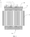
- FIG. 2 is a side view of a structure of a stator of a flat wire motor according to an embodiment of this application;
- FIG. 3 is a top view of a structure of a stator core according to an embodiment of this application;
- FIG. 4 is a schematic diagram of a structure of a hairpin coil according to an embodiment of this application;
- FIG. 5 is a top view of a structure of a flat wire conductor that is inserted in a winding slot according to an embodiment of this application;
- FIG. 6 is a distribution diagram of phase belts of a stator winding according to an embodiment of this application;
- FIG. 7 is a schematic diagram of a connection mode of a parallel branch according to an embodiment of this application;
- FIG. 8 is a schematic diagram of a circuit connection of three phase windings according to an embodiment of this application;
- FIG. 9 is a schematic diagram of a connection of a first parallel branch of a U-phase winding according to an embodiment of this application;
- FIG. 10 is a schematic diagram of a connection of a second parallel branch of a U-phase winding according to an embodiment of this application;
- FIG. 11 is a schematic diagram of a connection of a first parallel branch of a U-phase winding according to another embodiment of this application;
- FIG. 12 is a schematic diagram of a connection of a second parallel branch of a U-phase winding according to another embodiment of this application;
- FIG. 13 is a schematic diagram of a connection of a first parallel branch of a U-phase winding according to still another embodiment of this application;
- FIG. 14 is a schematic diagram of a connection of a second parallel branch of a U-phase winding according to still another embodiment of this application;
- FIG. 15 is a schematic diagram of a connection of two parallel branches of a U-phase winding according to still another embodiment of this application;
- FIG. 16 is a schematic diagram of a connection of a U-phase winding, a V-phase winding, and a W-phase winding according to still another embodiment of this application;
- FIG. 17 is a schematic diagram of a connection of a first parallel branch of a U-phase winding according to yet another embodiment of this application;
- FIG. 18 is a schematic diagram of a connection of a second parallel branch of a U-phase winding according to yet another embodiment of this application;
- FIG. 19 is a distribution diagram of phase belts of a stator winding according to another embodiment of this application;
- FIG. 20 is a schematic diagram of a connection of a first parallel branch of a U-phase winding according to another embodiment of this application; and
- FIG. 21 is a schematic diagram of a connection of a second parallel branch of a U-phase winding according to another embodiment of this application.
-
Reference numerals: 10-stator core; 10a-wire-inlet end; 10b-wire-outlet end; 11-winding slot; 20-stator winding; 20a-plug-wire end; 20b-welding end; 21-flat wire conductor; 22-hairpin coil; 221-leg; 222-connected part; and 223-bent part.
DESCRIPTION OF EMBODIMENTS
-
To make objectives, technical solutions, and advantages of this application clearer, the following further describes this application in detail with reference to the accompanying drawings.
-
Terms used in the following embodiments are merely intended to describe specific embodiments, but are not intended to limit this application. The terms "one", "a" and "this" of singular forms used in this specification and the appended claims of this application are also intended to include expressions such as "one or more", unless otherwise specified in the context clearly.
-
Reference to "an embodiment", "some embodiments", or the like described in this specification indicates that one or more embodiments of this application include a specific feature, structure, or characteristic described with reference to the embodiment. Therefore, statements such as "in an embodiment", "in some embodiments", "in some other embodiments", and "in other embodiments", that appear at different places in this specification do not necessarily mean referring to a same embodiment, instead, they mean "one or more but not all of the embodiments", unless otherwise specifically emphasized. The terms "include", "contain", "have", and their variants all mean "include but are not limited to", unless otherwise specifically emphasized.
-
At present, a driving motor of a new energy vehicle is mainly a permanent magnet synchronous motor. In the permanent magnet synchronous motor, a motor stator may use a circular wire conductor or a flat copper wire conductor based on a sectional shape of a stator winding. A motor using a flat copper wire conductor is referred to as a flat wire motor. The flat wire motor may effectively improve a wire slot fill, a power density, and a torque density. However, with an increasing quantity of flat wire conductors in a winding slot, in some designs, a quantity of parallel circuits is increased. In addition, complexity of outgoing lines of parallel circuits may be increased. In an existing stator winding, a circuit design of parallel branches of the existing stator winding makes it difficult to switch positions of wire-in ends and wire-out ends of a plurality of parallel circuits between a plug-wire end and a welding end of the stator winding as required. Therefore, the existing stator winding has an inflexible connection structure and poor adaptability. To resolve the foregoing problems, an embodiment of this application provides a stator of a flat wire motor.
-
For ease of understanding, the following first describes proper nouns used in this application.
-
A stator is a stationary part in a motor, and a function of the stator is to generate a rotating magnetic field.
-
A rotor is a rotating part in a motor, and a function of the rotor is to implement conversion between electric energy and mechanical energy.
-
A span, also referred to as a first pitch, is a distance that two edges of a same element in a motor winding span an armature surface, and is usually represented by a quantity of winding slots formed on a stator core.
-
FIG. 1 is a schematic diagram of a three-dimensional structure of a stator of a flat wire motor according to an embodiment of this application. FIG. 2 is a side view of a structure of a stator of a flat wire motor according to an embodiment of this application. As shown in FIG. 1 and FIG. 2, in an embodiment of this application, the stator includes a stator core 10 and a stator winding 20.
-
FIG. 3 is a top view of a structure of a stator core according to an embodiment of this application. As shown in FIG. 3, an inner wall of the stator core 10 is provided with a plurality of winding slots 11. A quantity of the winding slots 11 may be represented by M, where M may be a natural number that is a multiple of 3, and may specifically be 54. Refer to FIG. 1 to FIG. 3. M winding slots 11 are disposed on the inner wall of the stator core 10, and are uniformly disposed in a circumferential direction of the inner wall of the stator core 10. Any one of the winding slots 11 extends in an axial direction (a Z direction shown in FIG. 1 and FIG. 2) of the stator core 10, and passes through the inner wall of the stator core 10 in the axial direction of the stator core 10. The stator core 10 has a wire-inlet end 10a and a wire-outlet end 10b in the axial direction of the stator core 10, and any one of the winding slots 11 may extend from the wire-inlet end 10a to the wire-outlet end 10b.
-
Refer to FIG. 1 and FIG. 2, in an embodiment of this application, the stator winding 20 includes flat wire conductors 21 inserted in the winding slots 11, and cross sections of the flat wire conductors 21 may be rectangular. The flat wire conductors 21 may be formed by hairpin coils. FIG. 4 is a schematic diagram of a structure of a hairpin coil according to an embodiment of this application. As shown in FIG. 4, in this embodiment of this application, the hairpin coil 22 includes a leg 221 disposed in a winding slot 11, and a connected part 222 and a bent part 223 that are disposed outside the winding slot 11. The connected part 222 may be U-shaped or V-shaped. Refer to FIG. 1 and FIG. 4. In an embodiment of this application, after the hairpin coil 22 is inserted in the winding slot 11, the hairpin coil 22 may be bent to form the bent part 223. After insertion, the leg 221, inserted in the winding slot 11, of the hairpin coil 22 forms the flat wire conductor 21. After bending, head twisting directions of the bent part 223 of the hairpin coil 22 are consistent. After the hairpin coil 22 is inserted in the winding slot 11, the connected part 222 forms the plug-wire end 20a of the stator winding 20, and the bent part 223 forms the welding end 20b of the stator winding 20.
-
FIG. 5 is a top view of a structure of a flat wire conductor that is inserted in a winding slot according to an embodiment of this application. As shown in FIG. 5, in an embodiment of this application, N layers of flat wire conductors 21 may be disposed in any winding slot 11, where N may be 6 or 10. As shown in FIG. 5, in this embodiment of this application, N is 6. That is, six layers of flat wire conductors are disposed in each winding slot 11. It may be understood that a quantity of layers of the flat wire conductors 21 shown in FIG. 5 is only described as an example. Six or ten layers of flat wire conductors 21 may be disposed.
-
Still refer to FIG. 1 and FIG. 5. In an embodiment of this application, the flat wire conductors 21 inserted in the winding slots 11 are grouped and connected to form three phase windings. The three phase windings are a first-phase winding, a second-phase winding, and a third-phase winding, and respectively correspond to a U-phase winding, a V-phase winding, and a W-phase winding. Any one of the three phase windings may include a plurality of phase units. When the three phase windings are connected, phase units of the first-phase winding, phase units of the second-phase winding, and phase units of the third-phase winding are sequentially and periodically arranged along the inner wall of the stator core. FIG. 6 is a distribution diagram of phase belts of a stator winding according to an embodiment of this application. Refer to FIG. 5 and FIG. 6. In an embodiment of this application, three winding slots 11 that are adjacently disposed form one phase unit, and in one phase unit, all flat wire conductors 21 are in-phase. The U-phase winding, the V-phase winding, and the W-phase winding are alternately disposed based on phase units. Refer to FIG. 5 and FIG. 6. In an embodiment of this application, the flat wire conductors 21 in a same winding slot 11 are in-phase. In this case, interphase insulating paper is not needed for the flat wire conductors 21 of different layers in the same winding slots 11, so that insulation costs of a motor may be reduced.
-
FIG. 7 is a schematic diagram of a connection mode of flat wire conductors for forming a parallel branch according to an embodiment of this application. Refer to FIG. 5 and FIG. 7. In an embodiment of this application, each phase winding may include two parallel branches. Any one of the parallel branches may connect flat wire conductors 21 of M·N/3P layers, and any one of the flat wire conductors 21 in the any one of the parallel branches is connected to an in-phase flat wire conductor 21 of an adjacent layer or a same layer in a winding slot 11 at an adjacent span. FIG. 8 is a schematic diagram of a circuit connection of three phase windings according to an embodiment of this application. As shown in FIG. 8, in this embodiment of this application, the three phase windings of a stator winding each include two parallel circuits.
-
Still refer to FIG. 7. In an embodiment of this application, a span of any parallel branch in a first layer is 9, and a combination of spans in an Nth layer is 10, 10, and 7, or 8, 8, and 11. In a possible implementation of this application, a combination of spans of any one of the parallel branches in the first layer is 10, 10, and 7, or 8, 8, and 11, and a span in the Nth layer is 9. In a possible implementation of this application, a span of any parallel branch from a second layer to an (N-1)th layer is 9.
-
In a possible implementation of this application, a wire-out end of any one of the parallel branches leads out from a flat wire conductor of the first layer or a flat wire conductor of the Nth layer. In this structure, a wire-in end and a wire-out end of a parallel branch can conveniently lead out.
-
In another possible implementation of this application, each phase winding includes a first parallel branch and a second parallel branch. A wire-in end of the first parallel branch is connected to a flat wire conductor of an (n1)th layer in an (m1)th winding slot, and a wire-out end of the first parallel branch is connected to a flat wire conductor of an (n2)th layer in an (m2)th winding slot. A difference between m1 and m2 is equal to a span. An absolute value of a difference between n1 and n2 is less than or equal to 1. An wire-in end of the second parallel branch is connected to a flat wire conductor of an (n1+2)th layer in the (m1)th winding slot, and a wire-out end of the second parallel branch is connected to a flat wire conductor of an (n2+2)th layer in the (m2)th winding slot, where m1 and m2 are natural numbers from 1 to M in a same phase winding, and n1 and n2 are natural numbers from 2 to N-2 in a same parallel branch. In the structure, positions of wire-in ends and wire-out ends of different parallel branches of a same phase winding are close to each other, so that the wire-in ends and the wire-out ends may lead out from flat wire conductors of different layers in a same winding slot, to facilitate connection.
-
An embodiment of this application further provides a flat wire motor. The flat wire motor includes a rotor and the stator according to embodiments of this application. The rotor is disposed in a space enclosed by an inner wall of the stator core.
-
An embodiment of this application further provides a powertrain. The powertrain includes a reducer and the foregoing flat wire motor. The flat wire motor is in transmission connection with the reducer. Specifically, a drive shaft of the flat wire motor may be in transmission connection with an input shaft of the reducer through a transmission part, for example, a coupling, to output a driving force from the flat wire motor to the reducer.
-
An embodiment of this application provides a vehicle. The vehicle includes the foregoing powertrain. The powertrain is disposed in the vehicle and provides running power for the vehicle. Specifically, in this embodiment, the vehicle may be a new energy vehicle driven by electric energy. The new energy vehicle may be specifically a hybrid electric vehicle, a battery electric vehicle, a fuel cell electric vehicle, or the like, or may be a vehicle using an efficient accumulator, for example, a supercapacitor, a flywheel battery, or a flywheel accumulator as a source of electric energy.
-
The following describes in detail a connection mode of a specific parallel branch in embodiments of this application with reference to specific embodiments.
Embodiment 1
-
This embodiment provides a stator of a flat wire motor. The stator includes a stator core and a stator winding. The stator core has 54 winding slots, and a quantity of layers of conductors in each winding slot is 6. The stator winding includes a U-phase winding, a V-phase winding, and a W-phase winding. Each phase winding has two parallel branches. For a distribution diagram of phase belts of the stator winding in this embodiment, refer to FIG. 6. FIG. 9 is a schematic diagram of a connection of a first parallel branch of the U-phase winding in this embodiment. FIG. 10 is a schematic diagram of a connection of a second parallel branch of the U-phase winding in this embodiment. In this embodiment, wire-in ends and wire-out ends of the first parallel branch and the second parallel branch of each phase winding are connected to a flat wire conductor of a first layer.
-
As shown in FIG. 6, each winding slot has flat wire conductors of six layers. The first layer is denoted as L1, a second layer is denoted as L2, a third layer is denoted as L3, a fourth layer is denoted as L4, a fifth layer is denoted as L5, and a sixth layer is denoted as L6. The first layer is a bottom layer of the winding slot, and the sixth layer is a top layer of the winding slot. "+" represents a current flowing into a conductor and "-" represents a current flowing out of a conductor. It should be noted that distribution of the phase belts in FIG. 6 is only described as an example. Symbols "+" and "-" in FIG. 6 are exchanged, for example, replacing symbols "U+" with "U-", replacing symbols "U-" with "U+", and modifying a V phase and a W phase correspondingly are all within the protection scope of this application.
-
In FIG. 9 and FIG. 10, a solid line represents a wiring mode of a plug-wire end, and a dotted line represents a wiring mode of a welding end.
-
The following describes in detail a wiring mode of the first parallel branch of the U-phase winding in this embodiment with reference to FIG. 9. The following describes a wiring mode of the stator winding at the welding end only based on the connection mode represented by the dotted line in FIG. 9. A connecting wire at the plug-wire end of the stator winding may be directly connected through a connected part of a hairpin coil. For details, refer to the connection mode represented by the solid line in FIG. 9.
-
Refer to FIG. 9. In the first parallel branch of the U-phase winding, a first layer in a 48th slot is used as a wire-in end V1in. The first parallel branch enters from the first layer in the 48th slot and leads out from a second layer in a third slot, then enters from a first layer in a 12th slot and leads out from a second layer in a 21st slot, then enters from a third layer in a 30th slot and leads out from a fourth layer in a 39th slot, then enters from a fifth layer in the 48th slot and leads out from a sixth layer in the third slot, and then enters from a fifth layer in the 12th slot and leads out from a sixth layer in the 21st slot. In this case, after flat wire conductors are connected, the first parallel branch may traverse from a first layer to a sixth layer, and may be circumferentially disposed around the stator core for one circle. The first parallel branch performs a next traversal according to the foregoing method. Specifically, the first parallel branch enters from a sixth layer in a 28th slot and leads out from a fifth layer in a 19th slot, then enters a fourth layer in a 10th slot and leads out from a third layer in a first slot, then enters a fourth layer in a 46th slot and leads out from a third layer in a 37th slot, and then enters from a second layer in the 28th slot and leads out from a first layer in the 19th slot, and in this case, the first parallel branch completes a second traversal. Then, the first parallel branch enters from a first layer in the 10th slot and leads out from a second layer in the 19th slot, then enters from a first layer in the 28th slot and leads out from a second layer in the 37th slot, then enters from a third layer in the 46th slot and leads out from a fourth layer in the first slot, then enters from a fifth layer in the 10th slot and leads out from a sixth layer in the 19th slot, and then enters from a fifth layer in the 28th slot and leads out from a sixth layer in the 37th slot, and in this case, the first parallel branch completes a third traversal. Then, the first parallel branch enters from a sixth layer in a 47th slot and leads out from a fifth layer in a 38th slot, then enters from a fourth layer in a 29th slot and leads out from a third layer in a 20th slot, then enters from a fourth layer in an 11th slot and leads out from a third layer in a second slot, and then enters from a second layer in the 47th slot and leads out from a first layer in the 38th slot, and in this case, the first parallel branch completes a fourth traversal. Then, the first parallel branch enters from a first layer in the 29th slot and leads out from a second layer in the 38th slot, then enters from a first layer in the 47th slot and leads out from a second layer in the second slot, then enters from a third layer in the 11th slot and leads out from a fourth layer in the 20th slot, then enters from a fifth layer in the 29th slot and leads out from a sixth layer in the 38th slot, and then enters from a fifth layer in the 47th slot and leads out from a sixth layer in the second slot, and in this case, the first parallel branch completes a fifth traversal. Then, the first parallel branch enters from a sixth layer in the 12th slot and leads out from a fifth layer in the third slot, then enters from a fourth layer in the 48th slot and leads out from a third layer in the 39th slot, then enters from a fourth layer in the 30th slot and leads out from a third layer in the 21st slot, and then enters from a second layer in the 12th slot and leads out from a first layer in the third slot, and in this case, the first parallel branch leads out from the first layer in the third slot, to form a wire-out end U1out of the first parallel branch of the U-phase winding.
-
It should be noted that in the foregoing connection mode, for example, that "the first parallel branch enters from the first layer in the 48th slot and leads out from the second layer in the third slot" means that at the welding end, the flat wire conductor of the first layer in the 48th slot is connected to the flat wire conductor of the second layer in the third slot.
-
The following describes in detail a wiring mode of the second parallel branch of the U-phase winding in this embodiment with reference to FIG. 10. The following describes a wiring mode of the stator winding at the welding end only based on the connection mode represented by the dotted line in FIG. 10. A connecting wire at the plug-wire end of the stator winding may be directly connected through a connected part of a hairpin coil. For details, refer to the connection mode represented by the solid line in FIG. 10.
-
Refer to FIG. 10. In the second parallel branch of the U-phase winding, a first layer in the 30th slot is used as a wire-in end V2in. The second parallel branch enters from the first layer in the 30th slot and leads out from a second layer in the 39th slot, then enters from a third layer in the 48th slot and leads out from a fourth layer in the third slot, then enters from a third layer in the 12th slot and leads out from a fourth layer in the 21st slot, and then enters from a fifth layer in the 30th slot and leads out from a sixth layer in the 39th slot, and in this case, the second parallel branch completes a first traversal. Then, the second parallel branch enters from a sixth layer in the 29th slot and leads out from a fifth layer in the 20th slot, then enters from a sixth layer in the 11th slot and leads out from a fifth layer in the second slot, then enters from a fourth layer in the 47th slot and leads out from a third layer in the 38th slot, then enters from a second layer in the 29th slot and leads out from a first layer in the 20th slot, and then enters from a second layer in the 11th slot and leads out from a first layer in the second slot, and in this case, the second parallel branch completes a second traversal. Then, the second parallel branch enters from a first layer in the 11th slot and leads out from a second layer in the 20th slot, then enters from a third layer in the 29th slot and leads out from a fourth layer in the 38th slot, then enters from a third layer in the 47th slot and leads out from a fourth layer in the second slot, and then enters from a fifth layer in the 11th slot and leads out from a sixth layer in the 20th slot, and in this case, the second parallel branch completes a third traversal. Then, the second parallel branch enters from a sixth layer in the 10th slot and leads out from a fifth layer in the first slot, then enters from a sixth layer in the 46th slot and leads out from a fifth layer in the 37th slot, then enters from a fourth layer in the 28th slot and leads out from a third layer in the 19th slot, then enters from a second layer in the 10th slot and leads out from a first layer in the first slot, and then enters from a second layer in the 46th slot and leads out from a first layer in the 37th slot, and in this case, the second parallel branch completes a fourth traversal. Then, the second parallel branch enters from a first layer in the 46th slot and leads out from a second layer in the first slot, then enters from a third layer in the 10th slot and leads out from a fourth layer in the 19th slot, then enters from a third layer in the 28th slot and leads out from a fourth layer in the 37th slot, and then enters from a fifth layer in the 46th slot and leads out from a sixth layer in the first slot, and in this case, the second parallel branch completes a fifth traversal. Then, the second parallel branch enters from a sixth layer in the 47th slot and leads out from a fifth layer in the 39th slot, then enters from a sixth layer in the 30th slot and leads out from a fifth layer in the 21st slot, then enters from a fourth layer in the 12th slot and leads out from a third layer in the third slot, then enters from a second layer in the 48th slot and leads out from a first layer in the 39th slot, and then enters from a second layer in the 30th slot and leads out from a first layer in the 21st layer. In this case, the second parallel branch leads out from the first layer in the 21st layer, to form a wire-out end U2out in the second parallel branch of the U-phase winding.
-
In the foregoing wiring mode, for example, that "the second parallel branch enters from the first layer in the 30th slot and leads out from the second layer in the 39th slot" may be understood with reference to relevant explanations in the wiring mode in FIG. 9. Details are not described herein again.
-
As shown in FIG. 6, FIG. 9, and FIG. 10, in this embodiment, a combination of spans in the first layer in the first parallel branch is 9 and 9, a combination of spans in the sixth layer is 10, 10, and 7, and each of spans between every adjacent two layers from the second layer to the fifth layer is 9. Ulin, Ulout, U2in, and U2out each lead out from the plug-wire end of the stator winding, that is, lead out from a side of the connected part of the hairpin coil. In this case, a connected part between U1in and U1out is disconnected, and U1in and U1out separately lead out by using a conducting wire. A connected part between U2in and U2out is disconnected, and U2in and U2out separately lead out by using a conducting wire. In this structure, spans of most flat wire conductors are the same. Therefore, when the stator winding is wound, hairpin coils of a same model may be used, so that a quantity of models of hairpin coils is reduced and automatic insertion is facilitated. In addition, spans of parallel branches are the same at the welding end, to facilitate connection.
-
A wiring mode of a first parallel branch of the V-phase winding and a wiring mode of a first parallel branch of the W-phase winding may be obtained through translation on the basis of FIG. 9. A wiring mode of a second parallel branch of the V-phase winding and a wiring mode of a second parallel branch of the W-phase winding may be obtained through translation on the basis of FIG. 10.
-
In this case, a wire-in end and a wire-out end of each of a first parallel branch and a second parallel branch of each phase winding are located on a first layer. The three phase windings may directly lead out in parallel, or may be connected by using busbars to lead out. Neutral points may be welded directly or connected together by using busbars.
-
In addition, in the foregoing wiring modes, each parallel branch traverses phase belts and flat wire conductor layers that can be arranged, so that each parallel branch can maintain a potential balance, and no cross current is generated. It can be learned from FIG. 6, FIG. 9, and FIG. 10, conductors in a same slot are in-phase. In this case, insulating paper is not needed between flat wire conductors, to reduce insulation costs.
Embodiment 2
-
This embodiment provides a stator. FIG. 11 is a schematic diagram of a connection of a first parallel branch of a U-phase winding in this embodiment. FIG. 12 is a schematic diagram of a connection of a second parallel branch of a U-phase winding in this embodiment.
-
Refer to FIG. 11 and FIG. 12. In comparison with Embodiment 1, positions of wire-in ends and wire-out ends of a first parallel branch and a second parallel branch of each phase winding are different from those in Embodiment 1.
-
As shown in FIG. 11, in this embodiment, a wire-in end U1in of the first parallel branch is a first layer in a 28th slot, and a wire-out end U1out of the first parallel branch is a second layer in a 19th slot. Based on Embodiment 1, the original flat wire conductor of the first layer in the 48th slot and the original flat wire conductor of the first layer in the third slot are connected to the plug-wire end of the stator winding, a connected part between the flat wire conductor of the first layer in the 28th slot and the flat wire conductor of the second layer in the 19th slot is disconnected at the plug-wire end of the stator winding, and then, the flat wire conductor of the first layer in the 28th slot and the flat wire conductor of the second layer in the 19th slot separately lead out by using a leading wire. A wiring mode of a flat wire conductor in another position may not be changed. In this connection mode, a combination of spans in the first layer is 9, 9, and 9, and a combination of spans in the sixth layer is 10, 10, and 7.
-
As shown in FIG. 12, in this embodiment, the wire-in end U2in of the second parallel branch is a third layer in the 28th slot, and the wire-out end U2out is a fourth layer in the 19th slot. Based on Embodiment 1, the original flat wire conductor of the first layer in the 30th slot and the flat wire conductor of the first layer in the 21st slot are connected at the plug-wire end of the stator winding, the connected part between a flat wire conductor of the third layer in the 28th slot and a flat wire conductor of the fourth layer in the 19th slot is disconnected at the plug-wire end of the stator winding, and then, the flat wire conductor of the third layer in the 28th slot and the flat wire conductor of the fourth layer in the 19th slot separately lead out by using a leading wire. A wiring mode of a flat wire conductor in another position may not be changed.
-
It can be learned from a comparison between Embodiment 1 and Embodiment 2 that when a wire-in end and a wire-out end of each parallel branch are not all disposed at the first layer, wire-in ends of two in-phase parallel branches may be disposed in a same winding slot and wire-out ends of two in-phase parallel branches may be disposed in another same winding slot at an adjacent span. Therefore, a leading wire distance between parallel branches may be effectively reduced, a wire-in end and a wire-out end of each parallel branch of the three phase windings may conveniently lead out in parallel or lead out after being connected by using a busbar, and lead-out distances are short.
Embodiment 3
-
This embodiment provides a stator. FIG. 13 is a schematic diagram of a connection of a first parallel branch of a U-phase winding in this embodiment. FIG. 14 is a schematic diagram of a connection of a second parallel branch of a U-phase winding in this embodiment.
-
Refer to FIG. 13 and FIG. 14. In comparison with Embodiment 1, positions of a wire-in end and a wire-out end of each of a first parallel branch and a second parallel branch of each phase are different from those in Embodiment 1. In addition, in this embodiment, both the wire-in end and the wire-out end of each parallel branch are disposed at a welding end of a stator winding.
-
As shown in FIG. 13, in this embodiment, a wire-in end U1in of the first parallel branch is a second layer in a second slot, and a wire-out end U1out is a first layer in a 47th slot. Based on Embodiment 1 (refer to the wiring mode shown in FIG. 9), the original flat wire conductor of the first layer in the 48th slot and the original flat wire conductor of the first layer in the third slot are connected at the plug-wire end of the stator winding, the bent part between the flat wire conductor of the second layer in the second slot and the flat wire conductor of the first layer in the 47th slot is disconnected at the welding end of the stator winding, and then, the flat wire conductor of the second layer in the second slot and the flat wire conductor of the first layer in the 47th slot separately lead out by using a leading wire. A wiring mode of a flat wire conductor in another position may not be changed.
-
As shown in FIG. 14, in this embodiment, the wire-in end U2in of the second parallel branch is a fourth layer in the second slot, and the wire-out end U2out is a third layer in the 47th slot. Based on Embodiment 1 (refer to the wiring mode shown in FIG. 10), the original flat wire conductor of the first layer in the 30th slot and the flat wire conductor of the first layer in the 21st slot are connected at the plug-wire end of the stator winding, the connected part between the flat wire conductor of the fourth layer in the second slot and the flat wire conductor of the third layer in the 47th slot is disconnected at the plug-wire end of the stator winding, and then, the flat wire conductor of the fourth layer in the second slot and the flat wire conductor of the third layer in the 47th slot separately lead out by using a leading wire. A wiring mode of a flat wire conductor in another position may not be changed.
-
Compared with Embodiment 1, the wire-in end and the wire-out end of each parallel branch in Embodiment 3 are switched from the plug-wire end of the stator winding to the welding end of the stator winding. The switching form is simple and easy, and positions of the wire-in end and the wire-out end may be flexibly selected. In Embodiment 3, by using this wiring mode, wire-in ends of two parallel branches are located in a same winding slot, wire-out ends are located in a same winding slot. Therefore, a connection distance may be smaller.
-
FIG. 15 is a schematic diagram of a connection of two parallel branches of the U-phase winding in this embodiment. FIG. 16 is a schematic diagram of a connection of the U-phase winding, a V-phase winding, and a W-phase winding in this embodiment. With reference to FIG. 13 to FIG. 16, wire-in ends and wire-out ends of six parallel branches of the three phase windings are close to each other, and may directly lead out in parallel, or may lead out after being connected together by using a busbar. Therefore, lead-out distances of the wire-in ends and the wire-out ends are short, and the wire-in ends and the wire-out ends may lead out from the welding end.
Embodiment 4
-
This embodiment provides a stator. FIG. 17 is a schematic diagram of a connection of a first parallel branch of a U-phase winding in this embodiment. FIG. 18 is a schematic diagram of a connection of a second parallel branch of a U-phase winding in this embodiment.
-
Refer to FIG. 17 and FIG. 18. In comparison with Embodiment 1, positions of a wire-in end and a wire-out end of each of the first parallel branch and the second parallel branch of each phase are the same as those in Embodiment 1, and a difference lies in that a span of each parallel branch in a first layer and a sixth layer is changed. In Embodiment 1, a combination of spans in the first layer is 9 and 9, and a combination of spans in the sixth layer is 10, 10, and 7. However, in Embodiment 4, the combination of spans of the first layer is 9 and 9, and the combination of spans in the sixth layer is 8, 8, and 11.
-
FIG. 17 shows only a wiring mode of the first parallel branch at the first layer and the sixth layer. For wiring modes of the remaining intermediate layers from the second layer to the fifth layer, refer to FIG. 9 in Embodiment 1. FIG. 18 shows only a wiring mode of the second parallel branch at the first layer and the sixth layer. For wiring modes of the remaining intermediate layers from the second layer to the fifth layer, refer to FIG. 10 in Embodiment 1.
Embodiment 5
-
This embodiment provides a stator. In the stator, a stator core has 54 winding slots, and a quantity of layers of conductors in each winding slot is 10. The stator winding includes a U-phase winding, a V-phase winding, and a W-phase winding. Each phase winding has two parallel branches. FIG. 19 is a distribution diagram of phase belts of a stator winding in an embodiment. FIG. 20 is a schematic diagram of a connection of a first parallel branch of a U-phase winding in an embodiment. FIG. 21 is a schematic diagram of a connection of a second parallel branch of a U-phase winding in an embodiment.
-
As shown in FIG. 19, each winding slot has flat wire conductors of 10 layers. A first layer is denoted as L1, a second layer is denoted as L2, a third layer is denoted as L3, a fourth layer is denoted as L4, a fifth layer is denoted as L5, a sixth layer is denoted as L6, a seventh layer is denoted as L7, an eighth layer is denoted as L8, a ninth layer is denoted as L9, and a 10th layer is denoted as L10. The first layer is a bottom layer of the winding slot, and the 10th layer is a top layer of the winding slot. "+" represents a current flowing into a conductor and "-" represents a current flowing out of a conductor. It should be noted that distribution of the phase belts in FIG. 19 is only described as an example. Symbols "+" and "-" in FIG. 19 are exchanged, for example, replacing symbols "U+" with "U-", replacing symbols "U-" with "U+", and modifying a V phase and a W phase correspondingly are all within the protection scope of this application.
-
In FIG. 20 and FIG. 21, a solid line represents a wiring mode of a plug-wire end, and a dotted line represents a wiring mode of a welding end.
-
The following describes in detail a wiring mode of the first parallel branch of the U-phase winding in this embodiment with reference to FIG. 20. The following describes a wiring mode of the stator winding at the welding end only according to the connection mode represented by the dotted line in FIG. 20. A connecting wire at the plug-wire end of the stator winding may be directly connected through a connected part of a hairpin coil. For details, refer to the connection mode represented by the solid line in FIG. 20.
-
Refer to FIG. 20. In the first parallel branch of the U-phase winding, a second layer in a first slot is used as a wire-in end U1in. As the wire-in end, the second layer in the first slot is not connected, at the welding end of the stator winding, to a flat wire conductor of another layer. Then, the first parallel branch enters from a third layer in a 10th slot and leads out from a fourth layer in a 19th slot, then enters from a fifth layer in a 28th slot and leads out from a sixth layer in a 37th slot, then enters from a fifth layer in a 46th slot and leads out from a sixth layer in the first slot, then enters from a seventh layer in the 10th slot and leads out from an eighth layer in the 19th slot, and then enters from a ninth layer in the 28th slot and leads out from a 10th layer in the 37th slot. In this case, after flat wire conductors are connected, the first parallel branch traverses from a first layer to a sixth layer, and may be circumferentially disposed around the stator core for at least one circle.
-
The first parallel branch performs a next traversal according to the foregoing method. Specifically, the first parallel branch enters a 10th layer in a 47th slot and leads out from a ninth layer in a 38th slot, then enters a 10th layer in a 29th slot and leads out from an eighth layer in a 20th slot, then enters from an eighth layer in an 11th slot and leads out from a seventh layer in a second slot, then enters from an eighth layer in the 47th slot and leads out from a seventh layer in the 38th slot, then enters from a sixth layer in the 29th slot and leads out from a fifth layer in the 20th slot, then enters from a fourth layer in the 11th slot and leads out from a third layer in the second slot, then enters a fourth layer in the 47th slot and leads out from a third layer in the 38th slot, and then enters from a second layer in the 29th slot and leads out from a first layer in the 20th slot, and in this case, the first parallel branch completes a second traversal.
-
Then, the first parallel branch enters from a first layer in the 11th slot and leads out from a second layer in the 20th slot, then enters from a first layer in the 29th slot and leads out from a second layer in the 38th slot, then enters from a third layer in the 47th slot and leads out from a fourth layer in the second slot, then enters from a fifth layer in the 11th slot and leads out from a sixth layer in the 20th slot, then enters from a fifth layer in the 29th slot and leads out from a sixth layer in the 38th slot, then enters from a seventh layer in the 47th slot and leads out from an eighth layer in the second slot, and then enters from a ninth layer in the 11th slot and leads out from a 10th layer in the 20th slot, and in this case, the first parallel branch completes a third traversal.
-
Then, the first parallel branch enters from a 10th layer in a 30th slot and leads out from a ninth layer in a 21st slot, then enters from a 10th layer in a 12th slot and leads out from a ninth layer in a third slot, then enters from an eighth layer in a 48th slot and leads out from a seventh layer in a 39th slot, then enters from an eighth layer in the 30th slot and leads out from a seventh layer in the 21st slot, then enters from a sixth layer in the 12th slot and leads out from a fifth layer in the third slot, then enters from a fourth layer in the 48th slot and leads out from a third layer in the 39th slot, then enters form a fourth layer in the 30th slot and leads out from a third layer in the 21st slot, and then enters from a second layer in the 12th slot and leads out from a first layer in the third slot, and in this case, the first parallel branch completes a fourth traversal.
-
Then, the first parallel branch enters from a first layer in the 48th slot and leads out from a second layer in the third slot, then enters from a first layer in the 12th slot and leads out from a second layer in the 21st slot, then enters from a third layer in the 30th slot and leads out from a fourth layer in the 39th slot, then enters from a fifth layer in the 48th slot and leads out from a sixth layer in the third slot, then enters from a fifth layer in the 12th slot and leads out from a sixth layer in the 21st slot, then enters from a seventh layer in the 30th slot and leads out from an eighth layer in the 39th slot, and then enters from a ninth layer in the 48th slot and leads out from a 10th layer in the third slot, and in this case, the first parallel branch completes a fifth traversal.
-
Then, the first parallel branch enters from a 10th layer in the 10th slot and leads out from a ninth layer in the first slot, then enters from a 10th layer in the 46th slot and leads out from a ninth layer in the 37th slot, then enters from an eighth layer in the 28th slot and leads out from a seventh layer in the 19th slot, then enters from an eighth layer in the 10th slot and leads out from a seventh layer in the first slot, then enters from a sixth layer in the 46th slot and leads out from a fifth layer in the 37th slot, then enters from a fourth layer in the 28th slot and leads out from a third layer in the 19th slot, then enters from a fourth layer in the 10th slot and leads out from a third layer in the first slot, then enters from a second layer in the 46th slot and leads out from a first layer in the 37th slot, then enters from a first layer in the 28th slot and leads out from a second layer in the 37th slot, and then leads out from a first layer in the 46th slot, to form a wire-out end U1out of the first parallel branch of the U-phase winding.
-
The following describes in detail a wiring mode of the second parallel branch of the U-phase winding in this embodiment with reference to FIG. 21. The following describes a wiring mode of the stator winding at the welding end only based on the connection mode represented by the dotted line in FIG. 21. A connecting wire at the plug-wire end of the stator winding may be directly connected through a connected part of a hairpin coil. For details, refer to the connection mode represented by the solid line in FIG. 21.
-
Refer to FIG. 21. In the second parallel branch of the U-phase winding, a fourth layer in a first slot is used as a wire-in end U2in. As the wire-in end, the fourth layer in the first slot is not connected, at the plug-wire end of the stator winding, to a flat wire conductor of another layer. Then, the second parallel branch enters from a fifth layer in a 10th slot and leads out from a sixth layer in a 19th slot, then enters from a seventh layer in a 28th slot and leads out from an eighth layer in a 37th slot, then enters from a seventh layer in a 46th slot and leads out from an eighth layer in a first slot, then enters from a ninth layer in the 10th slot and leads out from a 10th layer in the 19th slot, and then enters from a ninth layer in the 28th slot and leads out from a 10th layer in the 37th slot, and in this case, the second parallel branch completes a first traversal.
-
Then, the second parallel branch enters from a 10th layer in a 30th slot and leads out from a ninth layer in a 21st slot, then enters from an eighth layer in a 12th slot and leads out from a seventh layer in a third slot, then enters from a sixth layer in a 48th slot and leads out from a fifth layer in a 39th slot, then enters from a sixth layer in the 30th slot and leads out from a fifth layer in the 21st slot, then enters from a fourth layer in the 12th slot and leads out from a third layer in the third slot, then enters from a second layer in the 48th slot and leads out from a first layer in the 39th slot, and then enters from a second layer in the 30th slot and leads out from a first layer in the 21st slot, and in this case, the second parallel branch completes a second traversal.
-
Then, the second parallel branch enters from a first layer in the 30th slot and leads out from a second layer in the 39th slot, then enters from a third layer in the 48th slot and leads out from a fourth layer in the third slot, then enters from a third layer in the 12th slot and leads out from a fourth layer in the 21st slot, then enters from a fifth layer in the 30th slot and leads out from a sixth layer in the 39th slot, then enters from a seventh layer in the 48th slot and leads out from an eighth layer in the third slot, then enters from a seventh layer in the 12th slot and leads out from an eighth layer in the 21st slot, then enters form a ninth layer in the 30th slot and leads out from a 10th layer in the 39th slot, and then enters from a ninth layer in the 48th slot and leads out from a 10th layer in the third slot, and in this case, the second parallel branch completes a third traversal.
-
Then, the second parallel branch enters from a 10th layer in a 47th slot and leads out from a ninth layer in a 38th slot, then enters from an eighth layer in a 29th slot and leads out from a seventh layer in a 20th slot, then enters from a sixth layer in an 11th slot and leads out from a fifth layer in a second slot, then enters from a sixth layer in the 47th slot and leads out from a fifth layer in the 38th slot, then enters from a fourth layer in the 29th slot and leads out from a third layer in the 20th slot, then enters from a second layer in the 11th slot and leads out from a first layer in the second slot, and then enters from a second layer in the 47th slot and leads out from a first layer in the 38th slot, and in this case, the second parallel branch completes a fourth traversal.
-
Then, the second parallel branch enters a first layer in the 47th slot and leads out from a second layer in a second slot, then enters a third layer in the 11th slot and leads out from a fourth layer in the 20th slot, then enters from a third layer in the 29th slot and leads out from a fourth layer in the 38th slot, then enters from a fifth layer in the 47th slot and leads out from a sixth layer in the second slot, then enters from a seventh layer in the 11th slot and leads out from an eighth layer in the 20th slot, then enters from a seventh layer in the 29th slot and leads out from an eighth layer in the 38th slot, then enters a ninth layer in the 47th slot and leads out from a 10th layer in the second slot, and then enters from a ninth layer in the 11th slot and leads out from a 10th layer in the 20th slot, and in this case, the second parallel branch completes a fifth traversal.
-
Then, the second parallel branch enters from a 10th layer in the 10th slot and leads out from a ninth layer in the first slot, then enters from an eighth layer in the 46th slot and leads out from a seventh layer in the 37th slot, then enters from a sixth layer in the 28th slot and leads out from a fifth layer in the 19th slot, then enters from a sixth layer in the 10th slot and leads out from a fifth layer in the first slot, then enters from a fourth layer in the 46th slot and leads out from a third layer in the 37th slot, then enters from a second layer in the 28th slot and leads out from a first layer in the 19th slot, then enters from a second layer in the 10th slot and leads out from a first layer in the first slot, then enters from a first layer in the 10th slot and leads out from a second layer in the 19th slot, then enters from a third layer in the 28th slot and leads out from a fourth layer in the 37th slot, and then leads out from a third layer in the 46th slot, to form a wire-out end U2out of the second parallel branch of the U-phase winding.
-
As shown in FIG. 19 to FIG. 21, in this embodiment, a combination of spans in the first layer of the first parallel branch is 9, 9, and 9, a combination of spans in the 10th layer is 10, 7, and 10, and each of spans between every adjacent two layers from the second layer to the ninth layer is 9. Ulin, Ulout, U2in, and U2out each lead out from the welding end of the stator winding, that is, lead out from a side of the bent part of the hairpin coil. U1in and U1out separately lead out by using a conducting wire, and U2in and U2out separately lead out by using a conducting wire. In this structure, spans of most flat wire conductors are the same. Therefore, when the stator winding is wound, hairpin coils of a same model may be used, so that a quantity of models of hairpin coils is reduced and automatic insertion is facilitated. In addition, spans of parallel branches are the same at the welding end, to facilitate connection.
-
A wiring mode of a first parallel branch of the V-phase winding and a wiring mode of a first parallel branch of the W-phase winding may be obtained through translation on the basis of FIG. 20. A wiring mode of a second parallel branch of the V-phase winding and a wiring mode of a second parallel branch of the W-phase winding may be obtained through translation on the basis of FIG. 21.
-
It can be understood that the foregoing specific embodiments are only described as examples. A span of the first layer and a span of the six layer can be interchanged, and same connection effects can be achieved.
-
In conclusion, the stator in embodiments of this application has the following advantages.
- (1). Because of a balanced circuit connection mode for parallel branches of each phase winding, generation of alternating current loss of the stator winding can be effectively reduced, a cross current between parallel branches is avoided, efficiency of the motor is improved, a temperature rise of the motor is reduced, and more possibilities are provided for a motor solution design. In addition, a wire-in end and a wire-out end of the stator winding can be changed as required, which is flexible and convenient.
- (2). In a motor with the winding structure in this application, few types of hairpin coils are used, hairpin coils at the welding end of the stator winding have same spans and same head twisting angles, welding points are symmetrically distributed around a circumference, wire-in ends and wire-out ends of the phase windings are regularly distributed, and difficulty of manufacturing the winding is low.
- (3). In the stator of this application, flat wire conductors in a same winding slot are in-phase, and interphase insulating paper is not needed for the flat wire conductors in the same winding slot. Therefore, insulation costs and insertion difficulty of the motor are reduced, and a copper slot fill of the motor is improved.
- (4). The stator winding of this application can implement flexible conversion between wire-in and wire-out ends at the plug-wire end and wire-in and wire-out ends at the welding end.
- (5). Incoming lines and outgoing lines of all parallel branches of the three phase windings may directly lead out in parallel, or may lead out after being connected together by using busbars. Accordingly, lead-out distances of the wire-in ends and the wire-out ends are short.
- (6). In the flat wire conductor of each layer in this application, a flat wire conductor of a first layer may be bent in a direction away from an axis of the stator core during wiring, and a flat wire conductor of a sixth layer may be bent in a direction close to the axis of the stator core during wiring. Therefore, wiring difficulty can be reduced.
-
The foregoing descriptions are merely specific implementations of this application, but are not intended to limit the protection scope of this application. Any variation or replacement readily figured out by a person skilled in the art within the technical scope disclosed in this application shall fall within the protection scope of this application. Therefore, the protection scope of this application shall be subject to the protection scope of the claims.