EP4089854B1 - Kontakteinrichtung für eine doppelstromschiene, gegenstück zu der kontakteinrichtung und kontaktsystem für zwei doppelstromschienen - Google Patents
Kontakteinrichtung für eine doppelstromschiene, gegenstück zu der kontakteinrichtung und kontaktsystem für zwei doppelstromschienen Download PDFInfo
- Publication number
- EP4089854B1 EP4089854B1 EP22172429.7A EP22172429A EP4089854B1 EP 4089854 B1 EP4089854 B1 EP 4089854B1 EP 22172429 A EP22172429 A EP 22172429A EP 4089854 B1 EP4089854 B1 EP 4089854B1
- Authority
- EP
- European Patent Office
- Prior art keywords
- contact
- busbar
- jack
- double
- socket
- Prior art date
- Legal status (The legal status is an assumption and is not a legal conclusion. Google has not performed a legal analysis and makes no representation as to the accuracy of the status listed.)
- Active
Links
Images

Classifications
-
- H—ELECTRICITY
- H01—ELECTRIC ELEMENTS
- H01R—ELECTRICALLY-CONDUCTIVE CONNECTIONS; STRUCTURAL ASSOCIATIONS OF A PLURALITY OF MUTUALLY-INSULATED ELECTRICAL CONNECTING ELEMENTS; COUPLING DEVICES; CURRENT COLLECTORS
- H01R13/00—Details of coupling devices of the kinds covered by groups H01R12/70 or H01R24/00 - H01R33/00
- H01R13/02—Contact members
- H01R13/15—Pins, blades or sockets having separate spring member for producing or increasing contact pressure
- H01R13/187—Pins, blades or sockets having separate spring member for producing or increasing contact pressure with spring member in the socket
-
- H—ELECTRICITY
- H01—ELECTRIC ELEMENTS
- H01R—ELECTRICALLY-CONDUCTIVE CONNECTIONS; STRUCTURAL ASSOCIATIONS OF A PLURALITY OF MUTUALLY-INSULATED ELECTRICAL CONNECTING ELEMENTS; COUPLING DEVICES; CURRENT COLLECTORS
- H01R11/00—Individual connecting elements providing two or more spaced connecting locations for conductive members which are, or may be, thereby interconnected, e.g. end pieces for wires or cables supported by the wire or cable and having means for facilitating electrical connection to some other wire, terminal, or conductive member, blocks of binding posts
- H01R11/11—End pieces or tapping pieces for wires, supported by the wire and for facilitating electrical connection to some other wire, terminal or conductive member
- H01R11/28—End pieces consisting of a ferrule or sleeve
-
- H—ELECTRICITY
- H01—ELECTRIC ELEMENTS
- H01R—ELECTRICALLY-CONDUCTIVE CONNECTIONS; STRUCTURAL ASSOCIATIONS OF A PLURALITY OF MUTUALLY-INSULATED ELECTRICAL CONNECTING ELEMENTS; COUPLING DEVICES; CURRENT COLLECTORS
- H01R13/00—Details of coupling devices of the kinds covered by groups H01R12/70 or H01R24/00 - H01R33/00
- H01R13/02—Contact members
- H01R13/22—Contacts for co-operating by abutting
- H01R13/24—Contacts for co-operating by abutting resilient; resiliently-mounted
- H01R13/2464—Contacts for co-operating by abutting resilient; resiliently-mounted characterized by the contact point
-
- H—ELECTRICITY
- H01—ELECTRIC ELEMENTS
- H01R—ELECTRICALLY-CONDUCTIVE CONNECTIONS; STRUCTURAL ASSOCIATIONS OF A PLURALITY OF MUTUALLY-INSULATED ELECTRICAL CONNECTING ELEMENTS; COUPLING DEVICES; CURRENT COLLECTORS
- H01R13/00—Details of coupling devices of the kinds covered by groups H01R12/70 or H01R24/00 - H01R33/00
- H01R13/648—Protective earth or shield arrangements on coupling devices, e.g. anti-static shielding
-
- H—ELECTRICITY
- H01—ELECTRIC ELEMENTS
- H01R—ELECTRICALLY-CONDUCTIVE CONNECTIONS; STRUCTURAL ASSOCIATIONS OF A PLURALITY OF MUTUALLY-INSULATED ELECTRICAL CONNECTING ELEMENTS; COUPLING DEVICES; CURRENT COLLECTORS
- H01R24/00—Two-part coupling devices, or either of their cooperating parts, characterised by their overall structure
- H01R24/38—Two-part coupling devices, or either of their cooperating parts, characterised by their overall structure having concentrically or coaxially arranged contacts
-
- H—ELECTRICITY
- H01—ELECTRIC ELEMENTS
- H01R—ELECTRICALLY-CONDUCTIVE CONNECTIONS; STRUCTURAL ASSOCIATIONS OF A PLURALITY OF MUTUALLY-INSULATED ELECTRICAL CONNECTING ELEMENTS; COUPLING DEVICES; CURRENT COLLECTORS
- H01R2103/00—Two poles
-
- H—ELECTRICITY
- H01—ELECTRIC ELEMENTS
- H01R—ELECTRICALLY-CONDUCTIVE CONNECTIONS; STRUCTURAL ASSOCIATIONS OF A PLURALITY OF MUTUALLY-INSULATED ELECTRICAL CONNECTING ELEMENTS; COUPLING DEVICES; CURRENT COLLECTORS
- H01R25/00—Coupling parts adapted for simultaneous co-operation with two or more identical counterparts, e.g. for distributing energy to two or more circuits
- H01R25/16—Rails or bus-bars provided with a plurality of discrete connecting locations for counterparts
- H01R25/161—Details
- H01R25/162—Electrical connections between or with rails or bus-bars
Definitions
- the present invention relates to a double busbar with a contact device, a second double busbar with a counterpart to the contact device and a contact system comprising two double busbars.
- the present invention is described below mainly in connection with vehicle electrical systems. However, the invention can be used in any application in which electrical loads, in particular large electrical loads with considerable power of, for example, more than 10 kW or with considerable voltages of, for example, more than 100 V, are transmitted.
- electrically conductive sheet metal from a body can be used as a ground, which means that separate return lines are no longer required. This means that approximately half of all cables in the vehicle can be dispensed with.
- automotive high voltage with, for example, more than 300V or even more than 700V can be used.
- Busbars made of solid metal material can be used for automotive high voltage. If busbars are used, separate positive and negative terminals can be used for safety reasons.
- Minus rails may be required.
- the plus and minus rails can be designed as a double rail.
- the publication US 7 568 947 B2 relates to a high-current coaxial connection, as formed by two plug elements that can be connected to one another.
- An insulating bushing is housed in a contact bushing that is overlapped by a coupling receptacle, while a mating plug comprises a central mating contact bolt that is held in an insulating bushing, which in turn is housed in a mating contact bushing with which the coupling receptacle cooperates to connect the plug to the mating plug.
- both the contact bushing and the insulating bushing are then moved relative to a contact bolt resting on the mating contact bolt to build up a restoring force and the contact bushing is moved against the mating contact bolt.
- the publication CN 211 556 357 U describes a coaxial connector connection contact piece comprising a male terminal and a female terminal mated with the male terminal, the male terminal comprising a male terminal body and a hyperbolic inner spring of the male terminal disposed in the male terminal body, and a lug disposed at the end of the male terminal body; the female terminal comprising a female terminal body, a hyperbolic inner spring of the female terminal disposed in the female terminal body.
- a terminal lug, the male terminal body and the female terminal body are inserted into each other and firmly connected, and the male terminal lug and the female terminal lug are used to connect an external power cable.
- the publication CN 203 193 080 U describes a busbar comprising a first busbar body and a second busbar body, the first busbar body being attached to conductive pins; an electrical connector is attached to the second busbar body for mating with the conductive pins on the first busbar body.
- One object of the invention is therefore to provide an improved double busbar with a contact device, an improved double busbar with a counterpart to the contact device and an improved contact system for two double busbars using the simplest possible construction means.
- An improvement can, for example, relate to an improved radiation characteristic, in particular a reduced radiation of electromagnetic fields.
- busbars With busbars, the busbar for the supply line and the busbar for the return line can also be arranged very close together by stacking the two busbars so that they are congruent.
- the stacked busbars are individually electrically insulated. This arrangement can be referred to as a double busbar.
- the approach presented here proposes a double socket with contact lamella, which enables a coaxial guidance of the current flows also at the contact point.
- a first double busbar with a contact device is proposed, wherein the first double busbar has a first busbar and a second busbar which are separated from one another by insulation and are stacked on top of one another to form a stack, wherein the contact device has an outer contact socket and an inner contact socket arranged coaxially in the outer contact socket, wherein an outer lamellar band for contacting a counter-socket of a counterpart to the contact device is arranged on an inner side of the outer contact socket and an inner lamellar band for contacting a contact pin of the counterpart is arranged on an inner side of the inner contact socket, wherein the outer contact socket is arranged on a flat side of the first busbar and is electrically conductively connected to the first busbar, wherein the inner contact socket is electrically conductively connected to the second busbar and penetrates the first busbar.
- a second double busbar with a counterpart to the contact device of the first double busbar is proposed, wherein the second double busbar has a first busbar (108) and a second busbar which are separated from one another by insulation and are stacked on top of one another to form a stack, wherein the counterpart has a counter bushing for contacting the outer lamella band of the contact device and a contact pin arranged coaxially in the counter bushing for contacting the inner lamella band of the contact device, wherein the counter bushing is arranged on a flat side of the first busbar of the second double busbar and is electrically conductively connected to the first busbar, wherein the contact pin is electrically conductively connected to the second busbar of the second double busbar and penetrates the first busbar.
- a contact system for two double busbars wherein the double busbars each have two busbars, which are each separated from one another by insulation and are stacked on top of one another to form a stack, wherein a first of the double busbars has a contact device according to the approach presented here, and a second of the double busbars has a counterpart according to the approach presented here, wherein the outer counter socket is arranged on a flat side of a first busbar of the second double busbar and is electrically connected to the first busbar, wherein the contact pin is electrically connected to a second busbar of the second double busbar and penetrates the first busbar, wherein the outer contact socket is electrically connected to the outer counter socket via the outer lamella band and the inner contact socket is electrically connected to the contact pin via the inner lamella band.
- a busbar can be understood as a solid strip of sheet metal.
- the busbar can be made of an aluminum material or a copper material, for example.
- Aluminum or aluminum alloys have good electrical conductivity with low weight and low material costs. Copper or copper alloys can have higher electrical conductivity than aluminum or aluminum alloys. In addition, copper or a copper alloy can be oxidation-resistant and have a low contact resistance.
- the busbar can have a rectangular line cross-section.
- the busbar can be elongated and have a length of, for example, more than 0.5 m, preferably more than 1 m, and a width of, for example, between 0.5 cm and 10 cm, preferably between 1 cm and 5 cm.
- the busbar can also have a thickness of, for example, between 1 mm and 10 mm.
- the busbar can have insulation on all sides, i.e. be covered by insulation.
- the insulation can be made of a plastic material, for example.
- the plastic material can be a thermoplastic.
- the busbar can be overmolded with the thermoplastic.
- the insulation can have properties that are designed for automotive high-voltage voltages of up to 1000 volts direct current. In particular, the thickness of the insulation material can ensure dielectric strength against automotive high-voltage voltages.
- a double busbar can consist of two busbars with the same dimensions.
- the two busbars can be stacked on top of each other on their flat sides.
- the busbars can also be a short distance apart.
- the busbars can be arranged so that they are congruent.
- the double busbar can be covered with a plastic material.
- the double busbar can be covered with a fabric material.
- the fabric material can be wrapped around the double busbar as a fabric tape, for example.
- the double busbar can also be additionally shielded against the radiation of electromagnetic fields by an electrically conductive sheath.
- One busbar of the double busbar can be connected to a positive potential of the vehicle high-voltage voltage when installed.
- the other busbar of the double busbar can be connected to a negative potential of the vehicle high-voltage voltage.
- Current flows through the two busbars thus flow in opposite directions and are of equal magnitude. Due to the spatial proximity of the busbars in the With a double current rail, the resulting electromagnetic fields essentially cancel each other out completely.
- a contact socket can be made of a copper material.
- the contact socket can be rotationally symmetrical.
- the contact socket can be essentially hollow-cylindrical.
- the contact socket can have a connection geometry for electrically conductive connection to the respective busbar.
- the contact sockets can be connected to the busbars by friction welding.
- a lamella band can run in a ring shape along an inner diameter of the outer or inner contact socket.
- the lamella band can be electrically conductive and be electrically connected to the inside of the respective contact socket.
- the lamella band can have resilient lamellae.
- the lamella band can have a smaller inner diameter than the respective contact socket.
- the lamellae can be aligned essentially axially to the respective contact socket. When contact is made by the counterpart, the lamellae can be elastically deformed and press against the counterpart with a resulting restoring force. The elasticity of the lamellae can compensate for an axial offset and/or an angular offset between the contact device and the counterpart.
- a counter bushing can essentially correspond to a contact bushing.
- An outer diameter of the counter bushing can be smaller than the inner diameter of the outer contact bushing in the area of the outer lamella band.
- the outer diameter of the counter bushing can be larger than the inner diameter of the outer lamella band.
- the counter bushing can be designed without a lamella band.
- a contact pin can be a solid electrical conductor.
- the contact pin can be made of a copper material.
- the contact pin can be rotationally symmetrical.
- An outer diameter of the contact pin can be smaller than the inner diameter of the inner contact socket in the area of the inner lamella band.
- the outer diameter of the contact pin can be larger than the inner diameter of the inner lamella band.
- the contact pin can have a connection geometry for electrically conductive connection to the second busbar.
- the contact pin can be connected to the busbar by friction welding.
- the contact sockets are electrically insulated from one another.
- An insulating bushing can be arranged between the inner contact socket and the outer contact socket.
- the mating bushing and the contact pin are also electrically insulated from one another.
- An insulating bushing can also be arranged between the mating bushing and the contact pin.
- the insulating bushing can be rotationally symmetrical.
- the insulating bushing can be essentially hollow-cylindrical.
- the outer contact socket can have a circumferential groove on the inside, i.e. an annular groove, for the outer lamella band.
- the inner contact socket can have a circumferential groove on the inside for the inner lamella band. At least partial areas or the entirety of the lamella band assigned to the respective contact socket can be accommodated in such grooves.
- the lamella band can be fixed axially in the respective contact socket by a groove.
- the lamellae of the lamella band can protrude from the groove into an interior of the respective contact socket.
- the lamella band can be inserted into the groove as a round, bent strip with a length corresponding to the circumference of the groove.
- the lamella band can be pressed against a base of the groove by a restoring force.
- an annular gap for the counter bushing can be arranged between the outer contact bushing and the inner contact bushing.
- the gap can be wider than the counter bushing. On its inside, the gap can be limited by the insulation.
- the gap can be formed by a shoulder of the outer and/or inner contact bushing.
- the counter bushing can be inserted through the gap between the outer contact bushing and the inner contact bushing.
- the contact system can therefore have a low overall height.
- the insulator arranged between the outer contact socket and the inner contact socket can cover an end face of the inner contact socket.
- the insulator can have a hole for the contact pin.
- the contact pin can center itself on the hole.
- Lamellas of the outer lamellar band and/or the inner lamellar band can be elongated, extend substantially parallel to an axial direction of the outer and inner contact socket and protrude radially inward over an inner surface of the associated contact socket at least in regions.
- Lamellas of the outer lamellar band and/or the inner lamellar band can project elastically and radially inward over an inner surface of the associated contact socket.
- the lamella belts can each have an upper belt, a lower belt and a number of lamellas arranged transversely between the upper belt and the lower belt.
- the lamella belts can be stamped and bent parts.
- the lamella belts can have slots between the lamellas.
- the lamella belts can be easily bent through the slots.
- the belts can connect the individual lamellas to one another at both ends in a ladder-like manner.
- the lamellas can be pre-bent in an arc shape.
- the counter bushing and the contact pin can be centered in the contact device via the preferably curved and radially inward-projecting lamellae.
- the lamellae can be bent back elastically against the pre-bend and thus build up the restoring force as a contact force.
- Fig. 1 shows a sectional view of a contact system 100 according to an embodiment.
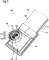
- Fig. 2 shows a perspective view of a double busbar 102 with a contact device 104.
- the contact system 100 here electrically connects two double busbars 102.
- the contact system can also connect a double busbar 102 to another electrical component.
- the contact system 100 consists of a contact device 104 and a counterpart 106 to the contact device 104.
- the double busbars 102 each consist of two parallel busbars 108, 110.
- the busbars 108, 110 each have an electrical insulation 112.
- the contact device 104 and the counterpart 106 are arranged at end regions of the double busbars 102.
- the contact device 104 and the counterpart 106 are aligned transversely to a main extension direction of the double busbars 102 and are each arranged on a flat side of the respective double busbar 102.
- the contact device 104 has two coaxially arranged contact sockets 114, 116.
- the contact sockets 114, 116 are essentially hollow cylindrical.
- An outer contact socket 114 encloses an inner contact socket 116.
- An insulation 112 is also arranged between the contact sockets 114, 116.
- the outer contact socket 114 is electrically conductively connected to the first busbar 108 of the first double busbar 102.
- the inner contact socket 116 is electrically conductively connected to the second busbar 110 of the first double busbar 102.
- the inner contact socket 116 runs electrically insulated through the first busbar 108 in order to reach the second busbar 110 arranged behind it.
- the counterpart 106 has a counter socket 118 and a contact pin 120.
- the counter socket 118 is essentially hollow-cylindrical.
- the counter socket 118 encloses the contact pin 120.
- An insulation 112 is arranged between the counter socket 118 and the contact pin 120.
- the counter socket 118 is electrically connected to the first busbar 108 of the second double busbar 102.
- the contact pin 120 is electrically connected to the second busbar 110 of the second double busbar 102.
- the contact pin 120 runs electrically insulated through the first busbar 108 in order to reach the second busbar 110 arranged behind it.
- the contact pin 120 leads the mating socket 118.
- the contact pin 120 thus contacts the inner contact socket 116 before the mating socket 18 contacts the outer contact socket.
- the contact pin 120 can have an insertion bevel at its end.
- the contact device 104 and the counterpart 106 can be aligned with one another and axially plugged together via the insertion bevel.
- the counter socket 118 is arranged in the outer contact socket 114.
- An outer lamellar strip 122 of the contact device 104 is arranged between the outer contact socket 114 and the counter socket 118.
- the outer lamellar strip 122 is clamped into the outer contact socket 114 when the counter socket 118 is inserted and connects the outer contact socket 114 and the counter socket 118 in an electrically conductive manner.
- the contact pin 120 is arranged within the inner contact socket 116.
- An inner lamellar band 124 of the contact device 104 is arranged between the inner contact socket 116 and the contact pin 120. The inner lamellar band 124 is clamped when the contact pin 120 is inserted into the inner contact socket 116 and connects the inner contact socket 116 and the contact pin 120 in an electrically conductive manner.
- the lamella strips 122, 124 each consist of a ladder-shaped strip of sheet metal. Due to a large number of parallel slots cut or punched into the strips, the lamella strips 122, 124 have an upper belt 126, a lower belt 128 and the lamellae 130 formed between the slots. The lamellae 130 are bent in an arc shape around a longitudinal axis of the strip. To insert into the contact sockets 114, 116, the strips are cut to length and wound spirally. Inside the contact sockets 114, 116, the winding is released and the strips are placed in a ring shape on the inside of the contact sockets 114, 116 due to a restoring force of the upper and lower belts 126, 128.
- the busbars 108, 110 are made of an aluminum material, while the contact sockets 114, 116, the counter socket 118 and the contact pin 120 are made of a copper material.
- the contact sockets 114, 116, the Counter socket 118 and the contact pin 120 are connected to the busbars 108, 110 by friction welding in order to obtain a secure electrically conductive connection.
- the lamella bands 122, 124 are arranged in a ring shape on the inside of grooves 132 that run around the contact sockets 114, 116.
- the grooves 132 fix the lamella bands 122, 124 axially and they cannot be axially displaced when the counter socket 118 is inserted into the outer contact socket 114 or when the contact pin 120 is inserted into the inner contact socket 116.
- the counter bushing 118 is arranged in an annular gap 134 between the outer contact bushing 114 and the insulation 112.
- the inner contact bushing 116 has a circumferential recess by a material thickness of the counter bushing 118 in order to provide space for the gap 134.
- the gap 134 nests the contact device 104 and the counterpart 106 and has a reduced overall height.
- the insulator 112 covers a front side of the inner contact socket 116. In this way, electrical contact between the mating socket 118 and the inner contact socket 116 can be safely avoided.
- the contact device 104 and the counterpart 106 each have an electrically insulating housing 136.
- the housing 136 also encloses the end regions of the double busbars 102.
- the two housings 136 are sealed against each other by a seal enclosing the outer contact socket 114.
- a double socket with contact lamella is presented as a contact system for a double rail energy transmission system.
- double rail systems can also be used to transmit electrical energy in the field of e-mobility, as they have the advantage of reducing electromagnetic field radiation due to field cancellation.
- the field cancellation results from a geometric arrangement of congruent rectangular rails lying one above the other at the smallest possible distance from each other.
- Components such as charging sockets, switch boxes or batteries require interfaces with a contacting system.
- the present approach presents a contact system that consists geometrically of two concentrically nested, but electrically isolated socket contacts.
- the lamella strips that serve as contact surfaces on the inner surfaces of the sockets are characteristic. These can be pre-punched as an endless strip, cut to length and inserted into an annular groove provided for this purpose in the socket. The necessary contact force is applied via the external screw connection of the housing.
- the contact system retains a degree of freedom in the plug-in direction, whereby further pre-tensioning of the inner socket elements using, for example, a wave spring to compensate for tolerances between the contact pairs on the plus and minus sides of the contact is not necessary.
- the contact system can be screwed or locked on the housing side. Possible areas of application include the interface to the charging socket, the interface to the switch box or battery, and use as a floating separation point of a segmented double rail in difficult installation spaces in which its entire length does not seem manageable.
- High-voltage (HV) double rail systems can transport high amounts of energy while simultaneously emitting low levels of electromagnetic field radiation.
- the rail system requires suitable interfaces suitable for outdoor use.
- the contact system presented here enables the double rail to be used in the installation space as an interface to the switch box or battery.
- the contact system can also be used as an interface to the charging socket, as an interface to the switch box or battery, and as a floating separation point of a segmented double rail in difficult installation spaces in which its entire length does not seem manageable.
- the contact is not made via the front surfaces of the socket geometries, but via a recessed contact lamella on the inside of the sockets.
- the contact system retains a degree of freedom in the plugging direction, and pre-tensioning one of the contact socket pairs via a spring element is not necessary.
- the illustration shows a cross-section of the double socket contact system with flanged-on busbars.
- the housing illustration is purely conceptual. In the finished construction, the header and plug housings are screwed or locked together.
- the inner contact pin which makes contact with the contact blade of the inner socket, is clearly visible in the cross-section.
- the outer contact system is represented by a socket mounted in the header (around the pin), which makes contact with the contact blade of the upper outer contact socket.
- the contact system can be used as a floating separation point on the header side if the double rail system cannot be installed in one piece (e.g. for assembly reasons).
- the contact system can also be used as an interface to the charging socket; here it is possible to screw it directly into one of the DC pins or to connect it to contacts (screwed, plugged) on the charging socket via rail pieces.
- the two sockets are covered by plastic geometries that are pushed back during the plugging process.
Landscapes
- Connector Housings Or Holding Contact Members (AREA)
Description
- Die vorliegende Erfindung betrifft eine Doppelstromschiene mit einer Kontakteinrichtung, eine zweite Doppelstromschiene mit einem Gegenstück zu der Kontakteinrichtung und ein Kontaktsystem umfassend zwei Doppelstromschienen.
- Die vorliegende Erfindung wird im Folgenden hauptsächlich in Verbindung mit Fahrzeugbordnetzen beschrieben. Die Erfindung kann aber in jeder Anwendung genutzt werden, in welcher elektrische Lasten, insbesondere große elektrische Lasten mit erheblichen Leistungen von beispielsweise mehr als 1 0kW bzw. mit erheblichen Spannungen von beispielsweise mehr als 100V, übertragen werden.
- In einem Niedervolt-Bordnetz eines Fahrzeugs kann elektrisch leitendes Blech einer Karosserie als Masse verwendet werden, wodurch auf separate Rückleitungen verzichtet werden kann. So kann näherungsweise auf die Hälfte aller Kabel im Fahrzeug verzichtet werden.
- Zum Übertragen großer elektrischer Lasten kann KFZ-Hochvoltspannung mit beispielsweise mehr als 300V oder sogar mehr als 700V verwendet werden. Für die KFZ-Hochvoltspannung können Stromschienen aus massivem Metallmaterial verwendet werden. Wenn Stromschienen verwendet werden, können aus Sicherheitsgründen separate Plus- und Minus-Schienen erforderlich sein. Die Plus- und Minus-Schienen können als Doppelschiene ausgebildet sein.
- Die Druckschrift
US 7 568 947 B2 betrifft eine Hochstrom-Koaxialverbindung, wie sie durch zwei miteinander verbindbare Steckerelemente gebildet ist. Eine Isolierbuchse ist in einer Kontaktbuchse untergebracht, die von einer Kupplungsaufnahme übergriffen wird, während ein Gegenstecker einen zentralen Gegenkontaktbolzen umfasst, der in einer Isolierbuchse gehalten ist, die wiederum in einer Gegenkontaktbuchse untergebracht ist, mit der die Kupplungsaufnahme zur Verbindung des Steckers mit dem Gegenstecker zusammenwirkt. Beim Verbinden des Steckers mit dem Gegenstecker wird dann sowohl die Kontaktbuchse als auch die Isolierbuchse relativ zu einem an dem Gegenkontaktbolzen anliegenden Kontaktbolzen zum Aufbau einer Rückstellkraft bewegt und die Kontaktbuchse gegen den Gegenkontaktbolzen bewegt. - Die Druckschrift
CN 211 556 357 U beschreibt ein Koaxialanschluss-Verbindungskontaktstück, umfassend einen männlichen Anschluss und einen weiblichen Anschluss, der mit dem männlichen Anschluss gepaart ist, wobei der männliche Anschluss einen männlichen Anschlusskörper und eine hyperbolische innere Feder des männlichen Anschlusses umfasst, die in dem männlichen Anschlusskörper angeordnet ist, und einen am Ende des männlichen Anschlusskörpers angeordneten Kabelschuh; der Buchsenanschluss umfasst einen Buchsenanschlusskörper, eine hyperbolische Innenfeder des Buchsenanschlusses, die in dem Buchsenanschlusskörper angeordnet ist. Eine Anschlussfahne, der Steckeranschlusskörper und der Buchsenanschlusskörper sind ineinander gesteckt und fest verbunden, und die männliche Anschlussfahne und die weibliche Anschlussfahne werden verwendet, um ein externes Stromkabel anzuschließen. - Die Druckschrift
CN 203 193 080 U beschreibt eine Stromschiene, die einen ersten Stromschienenkörper und einen zweiten Stromschienenkörper umfasst, wobei der erste Stromschienenkörper mit leitenden Stiften befestigt ist; am zweiten Stromschienenkörper ist ein elektrischer Steckverbinder zum Stecken mit den leitenden Stiften am ersten Stromschienenkörper befestigt. - Eine Aufgabe der Erfindung ist es daher, unter Einsatz konstruktiv möglichst einfacher Mittel eine verbesserte Doppelstromschiene mit einer Kontakteinrichtung, eine verbesserte Doppelstromschiene mit einem Gegenstück zu der Kontakteinrichtung und ein verbessertes Kontaktsystem für zwei Doppelstromschienen bereitzustellen. Eine Verbesserung kann hierbei beispielsweise eine verbesserte Abstrahlcharakteristik, insbesondere eine reduzierte Abstrahlung elektromagnetischer Felder betreffen.
- Die Aufgabe wird durch die Gegenstände der unabhängigen Ansprüche gelöst. Vorteilhafte Weiterbildungen der Erfindung sind in den abhängigen Ansprüchen, der Beschreibung und den begleitenden Figuren angegeben.
- In einem elektrisch angetriebenen Fahrzeug sind auch bei KFZ-Hochvoltspannung große elektrische Stromflüsse erforderlich, um eine Antriebsleistung beziehungsweise Brems- oder Rekuperationsleistung zu übertragen. Rund um stromdurchflossene Leiter des Fahrzeugs werden durch die Stromflüsse elektromagnetische Felder erzeugt. Um eine Abstrahlung der Felder zu verringern oder auch zu verhindern, können die Leiter geschirmt werden. Alternativ oder ergänzend können die Leiter für die Hinleitung und die Rückleitung möglichst parallel und nah zusammen angeordnet werden, da sich die durch die entgegengesetzten Stromflüsse verursachten elektromagnetischen Felder gegenseitig auslöschen.
- Auch bei Stromschienen können die Stromschiene für die Hinleitung und die Stromschiene für die Rückleitung sehr nahe zusammen angeordnet werden, indem die beiden Stromschienen deckungsgleich aufeinandergestapelt werden. Die gestapelten Stromschienen sind dabei einzeln elektrisch isoliert. Diese Anordnung kann als Doppelstromschiene bezeichnet werden.
- Um den Effekt der Auslöschung auch an Kontaktstellen aufrecht zu erhalten, wird bei dem hier vorgestellten Ansatz eine Doppelbuchse mit Kontaktlamelle vorgeschlagen, der eine koaxiale Führung der Stromflüsse auch an der Kontaktstelle ermöglicht.
- Es wird erste Doppelstromschiene mit einer Kontakteinrichtung vorgeschlagen, wobei die erste Doppelstromschiene eine erste Stromschiene und eine zweite Stromschiene aufweist, die durch eine Isolierung voneinander separiert sind und zu einem Stapel übereinandergestapelt sind, wobei die Kontakteinrichtung eine äußere Kontaktbuchse und eine koaxial in der äußeren Kontaktbuchse angeordnete innere Kontaktbuchse aufweist, wobei auf einer Innenseite der äußeren Kontaktbuchse ein äußeres Lamellenband zum Kontaktieren einer Gegenbuchse eines Gegenstücks zu der Kontakteinrichtung angeordnet ist und auf einer Innenseite der inneren Kontaktbuchse ein inneres Lamellenband zum Kontaktieren eines Kontaktstifts des Gegenstücks angeordnet ist, wobei die äußere Kontaktbuchse auf einer Flachseite der ersten Stromschiene angeordnet ist und mit der ersten Stromschiene elektrisch leitend verbunden ist, wobei die innere Kontaktbuchse mit der zweiten Stromschiene elektrisch leitend verbunden ist und die erste Stromschiene durchdringt.
- Weiterhin wird eine zweite Doppelstromschiene mit einem Gegenstück zu der Kontakteinrichtung der ersten Doppelstromschiene vorgeschlagen, wobei die zweite Doppelstromschiene eine erste Stromschiene (108) und eine zweite Stromschiene aufweist, die durch eine Isolierung voneinander separiert sind und zu einem Stapel übereinandergestapelt sind, wobei das Gegenstück eine Gegenbuchse zum Kontaktieren des äußeren Lamellenbands der Kontakteinrichtung und einen koaxial in der Gegenbuchse angeordneten Kontaktstift zum Kontaktieren des inneren Lamellenbands der Kontakteinrichtung aufweist, wobei die Gegenbuchse auf einer Flachseite der ersten Stromschiene der zweiten Doppelstromschiene angeordnet ist und mit der ersten Stromschiene elektrisch leitend verbunden ist, wobei der Kontaktstift mit der zweiten Stromschiene der zweiten Doppelstromschiene elektrisch leitend verbunden ist und die erste Stromschiene durchdringt.
- Ferner wird ein Kontaktsystem für zwei Doppelstromschienen vorgeschlagen, wobei die Doppelstromschienen je zwei Stromschienen aufweisen, die jeweils durch eine Isolierung voneinander separiert sind und zu einem Stapel übereinandergestapelt sind, wobei eine erste der Doppelstromschienen eine Kontakteinrichtung gemäß dem hier vorgestellten Ansatz aufweist, und eine zweite der Doppelstromschienen ein Gegenstück gemäß dem hier vorgestellten Ansatz aufweist, wobei die äußere Gegenbuchse auf einer Flachseite einer ersten Stromschiene der zweiten Doppelstromschiene angeordnet ist und mit der ersten Stromschiene elektrisch leitend verbunden ist, wobei der Kontaktstift mit einer zweiten Stromschiene der zweiten Doppelstromschiene elektrisch leitend verbunden ist und die erste Stromschiene durchdringt, wobei die äußere Kontaktbuchse über das äußere Lamellenband elektrisch leitend mit der äußeren Gegenbuchse verbunden ist und die innere Kontaktbuchse über das innere Lamellenband elektrisch leitend mit dem Kontaktstift verbunden ist.
- Unter einer Stromschiene kann ein massiver Streifen Metallblech verstanden werden. Die Stromschiene kann beispielsweise aus einem Aluminiummaterial oder einem Kupfermaterial sein. Aluminium beziehungsweise Aluminiumlegierungen weisen eine gute elektrische Leitfähigkeit bei geringem Gewicht und geringen Materialkosten auf. Kupfer beziehungsweise Kupferlegierungen können eine höhere elektrische Leitfähigkeit als Aluminium beziehungsweise Aluminiumlegierungen aufweisen. Zusätzlich kann Kupfer beziehungsweise eine Kupferlegierung oxidationsbeständig sein und einen geringen Übergangswiderstand aufweisen. Die Stromschiene kann einen rechteckigen Leitungsquerschnitt aufweisen. Dabei kann die Stromschiene länglich sein und eine Länge von beispielsweise mehr als 0,5 m, vorzugsweise mehr als 1 m, und eine Breite von beispielsweise zwischen 0,5 cm und 10 cm, vorzugsweise zwischen 1 cm und 5 cm, aufweisen. Die Stromschiene kann ferner eine Dicke von beispielsweise zwischen 1 mm und 10 mm aufweisen. Die Stromschiene kann auf allen Seiten eine Isolierung aufweisen, d.h. von einer Isolierung umhüllt sein. Die Isolierung kann beispielsweise aus einem Kunststoffmaterial sein. Das Kunststoffmaterial kann ein Thermoplast sein. Die Stromschiene kann mit dem Thermoplast umspritzt sein. Die Isolierung kann Eigenschaften aufweisen, die für KFZ-Hochvoltspannung von bis zu 1000 Volt Gleichstrom ausgelegt sind. Insbesondere kann eine Materialstärke der Isolierung eine Durchschlagfestigkeit gegen die KFZ-Hochvoltspannung sicherstellen.
- Eine Doppelstromschiene kann aus zwei Stromschienen mit gleichen Abmessungen bestehen. Die beiden Stromschienen können an Flachseiten aufeinandergestapelt sein. Die Stromschienen können auch einen geringen Abstand zueinander aufweisen. Die Stromschienen können deckungsgleich angeordnet sein. Die Doppelstromschiene kann mit einem Kunststoffmaterial ummantelt sein. Alternativ oder ergänzend kann die Doppelstromschiene mit einem Gewebematerial ummantelt sein. Das Gewebematerial kann beispielsweise als Gewebeband um die Doppelstromschiene gewickelt sein. Die Doppelstromschiene kann auch zusätzlich durch einen elektrisch leitenden Mantel gegen die Abstrahlung von elektromagnetischen Feldern geschirmt sein.
- Die eine Stromschiene der Doppelstromschiene kann in verbautem Zustand mit einem Pluspotenzial der KFZ-Hochvoltspannung verbunden sein. Die andere Stromschiene der Doppelstromschiene kann mit einem Minuspotenzial der KFZ-Hochvoltspannung verbunden sein. Stromflüsse durch die beiden Stromschienen fließen so in entgegengesetzte Richtungen und sind gleich groß. Durch die räumliche Nähe der Stromschienen in der Doppelstromschiene kompensieren sich die resultierenden elektromagnetischen Felder im Wesentlichen vollständig.
- Eine Kontaktbuchse kann aus einem Kupfermaterial bestehen. Die Kontaktbuchse kann rotationssymmetrisch sein. Die Kontaktbuchse kann im Wesentlichen hohlzylindrisch sein. Die Kontaktbuchse kann eine Verbindungsgeometrie zum elektrisch leitenden Verbinden mit der jeweiligen Stromschiene aufweisen. Die Kontaktbuchsen können durch Reibschweißen mit den Stromschienen verbunden werden.
- Ein Lamellenband kann ringförmig entlang eines Innendurchmessers der äußeren beziehungsweise inneren Kontaktbuchse umlaufen. Das Lamellenband kann elektrisch leitend sein und elektrisch leitend mit der Innenseite der jeweiligen Kontaktbuchse verbunden sein. Das Lamellenband kann federnde Lamellen aufweisen. Das Lamellenband kann einen kleineren Innendurchmesser als die jeweilige Kontaktbuchse aufweisen. Die Lamellen können im Wesentlichen axial zu der jeweiligen Kontaktbuchse ausgerichtet sein. Die Lamellen können beim Kontaktieren durch das Gegenstück elastisch verformt werden und mit einer resultierenden Rückstellkraft gegen das Gegenstück drücken. Durch die Elastizität der Lamellen kann ein axialer Versatz und/oder ein Winkelversatz zwischen der Kontakteinrichtung und dem Gegenstück ausgeglichen werden.
- Eine Gegenbuchse kann im Wesentlichen einer Kontaktbuchse entsprechen. Ein Außendurchmesser der Gegenbuchse kann kleiner als der Innendurchmesser der äußeren Kontaktbuchse im Bereich des äußeren Lamellenbands sein. Der Außendurchmesser der Gegenbuchse kann größer als der Innendurchmesser des äußeren Lamellenbands sein. Die Gegenbuchse kann ohne Lamellenband ausgeführt sein.
- Ein Kontaktstift kann ein massiver elektrischer Leiter sein. Der Kontaktstift kann aus einem Kupfermaterial bestehen. Der Kontaktstift kann rotationssymmetrisch sein. Ein Außendurchmesser des Kontaktstifts kann kleiner als der Innendurchmesser der inneren Kontaktbuchse im Bereich des inneren Lamellenbands sein. Der Außendurchmesser des Kontaktstifts kann größer als der Innendurchmesser des inneren Lamellenbands sein. Der Kontaktstift kann eine Verbindungsgeometrie zum elektrisch leitenden Verbinden mit der zweiten Stromschiene aufweisen. Der Kontaktstift kann durch Reibschweißen mit der Stromschiene verbunden werden.
- Die Kontaktbuchsen sind elektrisch voneinander isoliert. Zwischen der inneren Kontaktbuchse und der äußeren Kontaktbuchse kann eine Isolierbuchse angeordnet sein. Ebenso sind die Gegenbuchse und der Kontaktstift elektrisch voneinander isoliert. Zwischen der Gegenbuchse und dem Kontaktstift kann ebenso eine Isolierbuchse angeordnet sein. Die Isolierbuchse kann rotationssymmetrisch sein. Die Isolierbuchse kann im Wesentlichen hohlzylindrisch sein.
- Die äußere Kontaktbuchse kann auf der Innenseite eine umlaufende Nut, d.h. eine Ringnut, für das äußere Lamellenband aufweisen. Alternativ oder ergänzend kann die innere Kontaktbuchse auf der Innenseite eine umlaufende Nut für das innere Lamellenband aufweisen. In solchen Nuten können zumindest Teilbereiche oder eine Gesamtheit des der jeweiligen Kontaktbuchse zugeordneten Lamellenbandes aufgenommen sein. Durch eine Nut kann das Lamellenband axial in der jeweiligen Kontaktbuchse fixiert sein. Die Lamellen des Lammellenbands können aus der Nut in einen Innenraum der jeweiligen Kontaktbuchse ragen. Das Lamellenband kann als rund gebogener Streifen mit einer einem Umfang der Nut entsprechenden Länge in die Nut eingelegt werden. Das Lamellenband kann durch eine Rückstellkraft gegen einen Grund der Nut gedrückt werden.
- Im Bereich des äußeren Lamellenbands kann ein ringförmiger Spalt für die Gegenbuchse zwischen der äußeren Kontaktbuchse und der inneren Kontaktbuchse angeordnet sein. Der Spalt kann breiter als die Gegenbuchse sein. Auf seiner Innenseite kann der Spalt durch die Isolierung begrenzt sein. Der Spalt kann durch einen Absatz der äußeren und/oder inneren Kontaktbuchse ausgebildet sein. Durch den Spalt kann die Gegenbuchse zwischen die äußere Kontaktbuchse und die Innere Kontaktbuchse eingeführt werden. So kann das Kontaktsystem eine geringe Bauhöhe aufweisen.
- Der zwischen der äußeren Kontaktbuchse und der inneren Kontaktbuchse angeordnete Isolator kann eine Stirnfläche der inneren Kontaktbuchse verdecken. Der Isolator kann ein Loch für den Kontaktstift aufweisen. Der Kontaktstift kann sich an dem Loch zentrieren.
- Lamellen des äußeren Lamellenbandes und/oder des inneren Lamellenbandes können länglich ausgebildet sein, sich im Wesentlichen parallel zu einer Axialrichtung der äußeren und inneren Kontaktbuchse erstrecken und zumindest bereichsweise über eine Innenoberfläche der zugehörigen Kontaktbuchse nach radial innen überstehen.
- Lamellen des äußeren Lamellenbandes und/oder des inneren Lamellenbandes können elastisch federnd über eine Innenoberfläche der zugehörigen Kontaktbuchse nach radial innen überstehen.
- Die Lamellenbänder können je einen oberen Gürtel, einen unteren Gürtel und eine Vielzahl von quer zwischen dem oberen Gürtel und dem unteren Gürtel angeordneten Lamellen aufweisen. Die Lamellenbänder können Stanzbiegeteile sein. Zwischen den Lamellen können die Lamellenbänder Schlitze aufweisen. Durch die Schlitze können die Lamellenbänder einfach gebogen werden. Die Gürtel können die einzelnen Lamellen an beiden Enden leiterartig miteinander verbinden. Die Lamellen können bogenförmig vorgebogen sein.
- Über die vorzugsweise bogenförmigen und nach radial innen ragenden Lamellen können die Gegenbuchse und der Kontaktstift in der Kontakteinrichtung zentriert werden. Beim Einführen der Gegenbuchse und des Kontaktstifts in die Kontaktbuchsen können die Lamellen gegen die Vorbiegung elastisch federnd zurückgebogen werden und so die Rückstellkraft als Kontaktkraft aufbauen.
- Nachfolgend wird ein vorteilhaftes Ausführungsbeispiel der Erfindung unter Bezugnahme auf die begleitenden Figuren erläutert. Es zeigen:
-
Fig. 1 eine Schnittdarstellung eines Kontaktsystems gemäß einem Ausführungsbeispiel. -
Fig. 2 eine perspektivische Darstellung auf eine Doppelstromschiene mit einer Kontakteinrichtung gemäß einem Ausführungsbeispiel. - Die Figuren sind lediglich schematische Darstellungen und dienen nur der Erläuterung der Erfindung. Gleiche oder gleichwirkende Elemente sind durchgängig mit den gleichen Bezugszeichen versehen.
-
Fig. 1 zeigt eine Schnittdarstellung eines Kontaktsystems 100 gemäß einem Ausführungsbeispiel.Fig. 2 zeigt eine perspektivische Darstellung auf eine Doppelstromschiene 102 mit einer Kontakteinrichtung 104. - Das Kontaktsystem 100 verbindet hier zwei Doppelstromschienen 102 elektrisch. Das Kontaktsystem kann auch eine Doppelstromschiene 102 mit einer anderen elektrischen Komponente verbinden. Das Kontaktsystem 100 besteht aus einer Kontakteinrichtung 104 und einem Gegenstück 106 zur Kontakteinrichtung 104.
- Die Doppelstromschienen 102 bestehen aus je zwei parallel verlaufenden Stromschienen 108, 110. Die Stromschienen 108, 110 weisen jeweils eine elektrische Isolierung 112 auf. Die Kontakteinrichtung 104 und das Gegenstück 106 sind an Endbereichen der Doppelstromscheinen 102 angeordnet. Dabei sind die Kontakteinrichtung 104 und das Gegenstück 106 quer zu einer Haupterstreckungsrichtung der Doppelstromschienen 102 ausgerichtet und jeweils an einer Flachseite der jeweiligen Doppelstromschiene 102 angeordnet.
- Die Kontakteinrichtung 104 weist zwei koaxial angeordnete Kontaktbuchsen 114, 116 auf. Die Kontaktbuchsen 114, 116 sind im Wesentlichen hohlzylindrisch. Eine äußere Kontaktbuchse 114 umschließt eine innere Kontaktbuchse 116. Zwischen den Kontaktbuchsen 114, 116 ist ebenfalls eine Isolierung 112 angeordnet. Die äußere Kontaktbuchse 114 ist elektrisch leitend mit der ersten Stromschiene 108 der ersten Doppelstromschiene 102 verbunden. Die innere Kontaktbuchse 116 ist elektrisch leitend mit der zweiten Stromschiene 110 der ersten Doppelstromschiene 102 verbunden. Die Innere Kontaktbuchse 116 verläuft elektrisch isoliert durch die erste Stromschiene 108, um die dahinter angeordnete zweite Stromschiene 110 zu erreichen.
- Das Gegenstück 106 weist eine Gegenbuchse 118 und einen Kontaktstift 120 auf. Die Gegenbuchse 118 ist im Wesentlichen hohlzylindrisch. Die Gegenbuchse 118 umschließt den Kontaktstift 120. Zwischen der Gegenbuchse 118 und dem Kontaktstift 120 ist eine Isolierung 112 angeordnet. Die Gegenbuchse 118 ist elektrisch leitend mit der ersten Stromschiene 108 der zweiten Doppelstromschiene 102 verbunden. Der Kontaktstift 120 ist elektrisch leitend mit der zweiten Stromschiene 110 der zweiten Doppelstromschiene 102 verbunden. Der Kontaktstift 120 verläuft elektrisch isoliert durch die erste Stromschiene 108, um die dahinter angeordnete zweite Stromschiene 110 zu erreichen.
- In einem Ausführungsbeispiel eilt der Kontaktstift 120 der Gegenbuchse 118 voraus. Damit kontaktiert der Kontaktstift 120 die innere Kontaktbuchse 116 bevor die Gegenbuchse 18 die äußere Kontaktbuchse kontaktiert. Der Kontaktstift 120 kann an seinem Ende eine Einführschräge aufweisen. Über die Einführschräge können die Kontakteinrichtung 104 und das Gegenstück 106 aneinander ausgerichtet und axial zusammengesteckt werden.
- Im kontaktierten Zustand des Kontaktsystems 100 ist die Gegenbuchse 118 in der äußeren Kontaktbuchse 114 angeordnet. Zwischen der äußeren Kontaktbuchse 114 und der Gegenbuchse 118 ist ein äußeres Lamellenband 122 der Kontakteinrichtung 104 angeordnet. Das äußere Lamellenband 122 wird beim Einstecken der Gegenbuchse 118 in die äußere Kontaktbuchse 114 eingeklemmt und verbindet die äußere Kontaktbuchse 114 und die Gegenbuchse 118 elektrisch leitend.
- Im kontaktierten Zustand des Kontaktsystems 100 ist der Kontaktstift 120 innerhalb der inneren Kontaktbuchse 116 angeordnet. Zwischen der inneren Kontaktbuchse 116 und dem Kontaktstift 120 ist ein inneres Lamellenband 124 der Kontakteinrichtung 104 angeordnet. Das innere Lamellenband 124 wird beim Einführen des Kontaktstifts 120 in die innere Kontaktbuchse 116 eingeklemmt und verbindet die innere Kontaktbuchse 116 und den Kontaktstift 120 elektrisch leitend.
- In einem Ausführungsbeispiel bestehen die Lamellenbänder 122, 124 jeweils aus einem leiterförmigen Streifen Metallblech. Durch eine Vielzahl von in den Streifen geschnittenen beziehungsweise gestanzten parallelen Schlitzen weisen die Lamellenbänder 122, 124 einen oberen Gurt 126, einen unteren Gurt 128 und die zwischen den Schlitzen ausgebildeten Lamellen 130 auf. Die Lamellen 130 sind um eine Längsachse des Streifens bogenförmig gebogen. Zum Einfügen in die Kontaktbuchsen 114, 116 werden die Streifen auf Länge geschnitten und spiralförmig gewickelt. Innerhalb der Kontaktbuchsen 114, 116 wird die Wicklung gelöst und die Streifen legen sich durch eine Rückstellkraft der oberen und unteren Gurte 126, 128 ringförmig an die Innenseiten der Kontaktbuchsen 114, 116 an.
- In einem Ausführungsbeispiel sind die Stromschienen 108, 110 aus einem Aluminiummaterial, während die Kontaktbuchsen 114, 116, die Gegenbuchse 118 und der Kontaktstift 120 aus einem Kupfermaterial sind. Die Kontaktbuchsen 114, 116, die Gegenbuchse 118 und der Kontaktstift 120 sind mit den Stromschienen 108, 110 durch Reibschweißen verbunden, um eine sichere elektrisch leitende Verbindung zu erhalten.
- In einem Ausführungsbeispiel sind die Lamellenbänder 122, 124 ringförmig auf Innenseiten um die Kontaktbuchsen 114, 116 umlaufenden Nuten 132 angeordnet. Durch die Nuten 132 sind die Lamellenbänder 122, 124 axial fixiert und können beim Einschieben der Gegenbuchse 118 in die äußere Kontaktbuchse 114 beziehungsweise beim Einschieben des Kontaktstifts 120 in die innere Kontaktbuchse 116 nicht axial verschoben werden.
- In einem Ausführungsbeispiel ist die Gegenbuchse 118 in einem ringförmigen Spalt 134 zwischen der äußeren Kontaktbuchse 114 und der Isolierung 112 angeordnet. Die innere Kontaktbuchse 116 weist einen umlaufenden Rücksprung um eine Materialstärke der Gegenbuchse 118 auf, um Raum für den Spalt 134 bereitzustellen. Durch den Spalt 134 sind die Kontakteinrichtung 104 und das Gegenstück 106 verschachtelt und weisen eine reduzierte Bauhöhe auf.
- In einem Ausführungsbeispiel verdeckt der Isolator 112 eine Stirnseite der inneren Kontaktbuchse 116. So kann ein elektrischer Kontakt zwischen der Gegenbuchse 118 und der inneren Kontaktbuchse 116 sicher vermieden werden.
- In einem Ausführungsbeispiel weisen die Kontakteinrichtung 104 und das Gegenstück 106 je ein elektrisch isolierendes Gehäuse 136 auf. Das Gehäuse 136 umschließt auch die Endbereiche der Doppelstromschienen 102. Die beiden Gehäuse 136 sind über eine die äußere Kontaktbuchse 114 umschließende Dichtung gegeneinander abgedichtet.
- Mit anderen Worten wird eine Doppelbuchse mit Kontaktlamelle als Kontaktsystem für ein Doppelschienen-Energieübertragungssystem vorgestellt.
- Zur Übertragung elektrischer Energie können neben klassischen Rundleiter- und Einzelschienensystemen im Bereich der E-Mobilität auch Doppelschienensysteme eingesetzt werden, da sie durch Feldauslöschung Vorteile bezüglich geringerer elektromagnetischer Feldabstrahlung aufweisen. Die Feldauslöschung resultiert aus einer geometrischen Anordnung von deckungsgleich übereinanderliegenden Reckteckschienen in möglichst geringem Abstand zueinander. Für die Anbindung dieser Doppelschienensysteme an Komponenten wie Ladedosen, Schaltboxen oder Batterien sind Schnittstellen mit einem Kontaktierungssystem erforderlich.
- Der vorliegende Ansatz stellt ein Kontaktierungssystem vor, das geometrisch aus zwei konzentrisch ineinander liegenden, elektrisch aber voneinander isolierten Buchsenkontakten besteht. Kennzeichnend sind die als Kontaktflächen an den Innenflächen der Buchsen eingebrachten Lamellenbänder. Diese können als Endlosband vorstanzt, abgelängt und in eine dafür in der Buchse vorgesehene Ringnut eingelegt werden. Die notwendige Kontaktkraft wird über die äußere Verschraubung des Gehäuses aufgebracht. Das Kontaktsystem behält einen Freiheitsgrad in Steckrichtung, wobei eine weitere Vorspannung der inneren Buchsenelemente mittels z. B. einer Wellenfeder zum Toleranzausgleich zwischen den Kontaktpaaren der Plus- und der Minusseite des Kontakts nicht erforderlich ist. Das Kontaktsystem kann gehäuseseitig verschraubt oder auch verriegelt werden. Als Einsatzgebiet kommen die Schnittstelle zur Ladedose, die Schnittstelle zur Schaltbox oder Batterie sowie die Verwendung als fliegende Trennstelle einer segmentierten Doppelschiene in schwierigen Bauräumen, in denen deren gesamte Länge nicht handhabbar erscheint, in Betracht.
- Im Rahmen der steigenden elektrischen Leistungsanforderungen im Rahmen der E-Mobilität rückt der Aspekt des Insassenschutzes vor elektromagnetischen Belastungen (ICNIRP) immer stärker in den Fokus. Hochvolt (HV)-Doppelschienensysteme können hohe Energiemengen bei gleichzeitig geringer elektromagnetischer Feldabstrahlung transportieren. Das Schienensystem benötigt geeignete außenraumtaugliche Schnittstellen. Durch das vorgestellte Kontaktsystem ist die Doppelschiene im Bauraum als Schnittstelle zur Schaltbox oder Batterie einsetzbar. Das Kontaktsystem kann auch als Schnittstelle zur Ladedose, als Schnittstelle zur Schaltbox oder Batterie, sowie als fliegende Trennstelle einer segmentierten Doppelschiene in schwierigen Bauräumen eingesetzt werden, in denen deren gesamte Länge nicht handhabbar erscheint.
- Die Herstellung des Kontakts erfolgt nicht über die Stirnflächen der Buchsengeometrien, sondern über eine eingelassene Kontaktlamelle auf den Innenseiten der Buchsen. Das Kontaktsystem behält einen Freiheitsgrad in Steckrichtung, die Vorspannung eines der Kontaktbuchsenpaare über ein Federelement ist nicht notwendig.
- Die Abbildung zeigt die Schnittdarstellung durch das Doppelbuchsenkontaktsystem mit angeflanschten Stromschienen. Die Gehäusedarstellung ist lediglich konzeptionell. In der fertigen Konstruktion werden Header- und Steckergehäuse miteinander verschraubt, bzw. verriegelt. Im Schnitt gut zu sehen ist der innere Kontaktstift, der in die Kontaktlamelle der inneren Buchse kontaktiert. Das äußere Kontaktsystem wird durch eine im Header angebrachte Buchse (um den Pin herum) dargestellt, die in die Kontaktlamelle der oberen äußeren Kontaktbuchse kontaktiert. Das Kontaktsystem kann auf Seiten des Headers als fliegende Trennstelle eingesetzt werden, falls das Doppelschienensystem (z. B. aus Montagegründen) nicht in einem Stück montiert werden kann. Ebenfalls kann das Kontaktsystem als Schnittstelle zur Ladedose eingesetzt werden, hier sind die Möglichkeiten gegeben, direkt in einen der DC-Pins zu verschrauben oder aber über Schienenstücke an Kontakte (geschraubt, gesteckt) der Ladedose anzubinden.
- Zur Sicherstellung des Berührschutzes und der Isolation der Potentiale werden die beiden Buchsen von Kunststoffgeometrien abgedeckt, die im Steckvorgang zurückgeschoben werden.
- Da es sich bei der vorhergehend detailliert beschriebenen Vorrichtungen um Ausführungsbeispiele handelt, können sie in üblicher Weise vom Fachmann in einem weiten Umfang modifiziert werden, ohne den Bereich der Erfindung, der durch die Ansprüche definiert ist, zu verlassen. Insbesondere sind die mechanischen Anordnungen und die Größenverhältnisse der einzelnen Elemente zueinander lediglich beispielhaft.
-
- 100
- Kontaktsystem
- 102
- Doppelstromschiene
- 104
- Kontakteinrichtung
- 106
- Gegenstück
- 108
- erste Stromschiene
- 110
- zweite Stromschiene
- 112
- Isolierung
- 114
- äußere Kontaktbuchse
- 116
- innere Kontaktbuchse
- 118
- Gegenbuchse
- 120
- Kontaktstift
- 122
- äußeres Lamellenband
- 124
- inneres Lamellenband
- 126
- oberer Gurt
- 128
- unterer Gurt
- 130
- Lamelle
- 132
- Nut
- 134
- Spalt
- 136
- Gehäuse
Claims (9)
- Erste Doppelstromschiene (102) mit einer Kontakteinrichtung (104), wobei die erste Doppelstromschiene (102) eine erste Stromschiene (108) und eine zweite Stromschiene (110) aufweist, die durch eine Isolierung (112) voneinander separiert sind und zu einem Stapel übereinandergestapelt sind, wobei die Kontakteinrichtung (104) eine äußere Kontaktbuchse (114) und eine koaxial in der äußeren Kontaktbuchse (114) angeordnete innere Kontaktbuchse (116) aufweist, wobei auf einer Innenseite der äußeren Kontaktbuchse (114) ein äußeres Lamellenband (122) zum Kontaktieren einer Gegenbuchse (120) eines Gegenstücks (106) zu der Kontakteinrichtung (104) angeordnet ist und auf einer Innenseite der inneren Kontaktbuchse (116) ein inneres Lamellenband (124) zum Kontaktieren eines Kontaktstifts (120) des Gegenstücks (106) angeordnet ist, wobei die äußere Kontaktbuchse (114) auf einer Flachseite der ersten Stromschiene (108) angeordnet ist und mit der ersten Stromschiene (108) elektrisch leitend verbunden ist, wobei die innere Kontaktbuchse (116) mit der zweiten Stromschiene (110) elektrisch leitend verbunden ist und die erste Stromschiene (108) durchdringt.
- Erste Doppelstromschiene (102) gemäß Anspruch 1, bei der die äußere Kontaktbuchse (114) auf der Innenseite eine umlaufende Nut (132) aufweist und das äußere Lamellenband (122) zumindest bereichsweise in der Nut (132) aufgenommen ist, und/oder
bei der die innere Kontaktbuchse (116) auf der Innenseite eine umlaufende Nut (132) aufweist, und das innere Lamellenband (122) zumindest bereichsweise in der Nut (132) aufgenommen ist. - Erste Doppelstromschiene (102) gemäß einem der vorhergehenden Ansprüche, bei der im Bereich des äußeren Lamellenbands (122) ein ringförmiger Spalt (134) zum Aufnehmen der Gegenbuchse (118) zwischen der äußeren Kontaktbuchse (114) und der inneren Kontaktbuchse (116) angeordnet ist.
- Erste Doppelstromschiene (102) gemäß einem der vorhergehenden Ansprüche, bei der eine zwischen der äußeren Kontaktbuchse (114) und der inneren Kontaktbuchse (116) angeordnete Isolierung (112) eine Stirnfläche der inneren Kontaktbuchse (116) verdeckt.
- Erste Doppelstromschiene (102) gemäß einem der vorhergehenden Ansprüche, bei der das äußere Lamellenband (122) einen oberen Gurt (126), einen unteren Gurt (128) und eine Vielzahl von quer zwischen dem oberen Gurt (126) und dem unteren Gurt (128) angeordneten Lamellen (130) aufweist und/oder das innere Lamellenband (124) einen oberen Gurt (126), einen unteren Gurt (128) und eine Vielzahl von quer zwischen dem oberen Gurt (126) und dem unteren Gurt (128) angeordneten Lamellen (130) aufweist.
- Erste Doppelstromschiene (102) gemäß einem der vorhergehenden Ansprüche, bei der Lamellen (130) des äußeren Lamellenbandes (122) und/oder des inneren Lamellenbandes (124) länglich ausgebildet sind, sich im Wesentlichen parallel zu einer Axialrichtung der äußeren und inneren Kontaktbuchse (114, 116) erstrecken und zumindest bereichsweise über eine Innenoberfläche der zugehörigen Kontaktbuchse (114, 116) nach radial innen überstehen.
- Erste Doppelstromschiene (102) gemäß einem der vorhergehenden Ansprüche, bei der Lamellen (130) des äußeren Lamellenbandes (122) und/oder des inneren Lamellenbandes (124) elastisch federnd über eine Innenoberfläche der zugehörigen Kontaktbuchse (114, 116) nach radial innen überstehen.
- Zweite Doppelstromschiene (102) mit einem Gegenstück (106) zu der Kontakteinrichtung (104) der ersten Doppelstromschiene (102) gemäß einem der Ansprüche 1 bis 7, wobei die zweite Doppelstromschiene (102) eine erste Stromschiene (108) und eine zweite Stromschiene (110) aufweist, die durch eine Isolierung (112) voneinander separiert sind und zu einem Stapel übereinandergestapelt sind, wobei das Gegenstück (106) eine Gegenbuchse (118) zum Kontaktieren des äußeren Lamellenbands (122) der Kontakteinrichtung (104) und einen koaxial in der Gegenbuchse (118) angeordneten Kontaktstift (120) zum Kontaktieren des inneren Lamellenbands (124) der Kontakteinrichtung (104) aufweist, wobei die Gegenbuchse (118) auf einer Flachseite der ersten Stromschiene (108) der zweiten Doppelstromschiene (102) angeordnet ist und mit der ersten Stromschiene (108) elektrisch leitend verbunden ist, wobei der Kontaktstift (120) mit der zweiten Stromschiene (110) der zweiten Doppelstromschiene (102) elektrisch leitend verbunden ist und die erste Stromschiene (108) durchdringt.
- Kontaktsystem (100), umfassend eine erste Doppelstromschiene (102) gemäß einem der Ansprüche 1 bis 7 und eine zweite Doppelstromschiene (102) gemäß Anspruch 8, wobei die äußere Kontaktbuchse (114) über das äußere Lamellenband (122) elektrisch leitend mit der äußeren Gegenbuchse (118) verbunden ist und die innere Kontaktbuchse (116) über das innere Lamellenband (124) elektrisch leitend mit dem Kontaktstift (120) verbunden ist.
Applications Claiming Priority (1)
| Application Number | Priority Date | Filing Date | Title |
|---|---|---|---|
| DE102021112300.3A DE102021112300B4 (de) | 2021-05-11 | 2021-05-11 | Kontakteinrichtung für eine doppelstromschiene, gegenstück zu der kontakteinrichtung und kontaktsystem für zwei doppelstromschienen |
Publications (2)
| Publication Number | Publication Date |
|---|---|
| EP4089854A1 EP4089854A1 (de) | 2022-11-16 |
| EP4089854B1 true EP4089854B1 (de) | 2024-10-30 |
Family
ID=81597853
Family Applications (1)
| Application Number | Title | Priority Date | Filing Date |
|---|---|---|---|
| EP22172429.7A Active EP4089854B1 (de) | 2021-05-11 | 2022-05-10 | Kontakteinrichtung für eine doppelstromschiene, gegenstück zu der kontakteinrichtung und kontaktsystem für zwei doppelstromschienen |
Country Status (3)
| Country | Link |
|---|---|
| EP (1) | EP4089854B1 (de) |
| CN (1) | CN115332849A (de) |
| DE (1) | DE102021112300B4 (de) |
Families Citing this family (2)
| Publication number | Priority date | Publication date | Assignee | Title |
|---|---|---|---|---|
| DE102024104774B4 (de) * | 2024-02-21 | 2026-05-07 | Schaeffler Technologies AG & Co. KG | Elektrische Bestromungseinrichtung für eine elektrische Maschine eines elektrisch betreibbaren Antriebsstrangs eines Kraftfahrzeugs |
| DE102024119320A1 (de) * | 2024-07-08 | 2026-01-08 | Karl Leibinger Asset Management Gmbh & Co. Kg | Steckbuchse zur Übertragung von hochfrequentem Strom, Stecksystem sowie elektrochirurgisches Gerät |
Family Cites Families (9)
| Publication number | Priority date | Publication date | Assignee | Title |
|---|---|---|---|---|
| US6746279B1 (en) * | 2000-11-07 | 2004-06-08 | Ixos Limited | Power distribution system |
| DE102007007541A1 (de) | 2007-02-15 | 2008-08-21 | Siemens Ag | Hochstrom-Koaxialverbindung mit zwei miteinander verbindbaren Steckelementen sowie Gradientenspule mit angeschlossener Hochstrom-Koaxialleitung |
| DE102007059521B4 (de) | 2007-12-11 | 2016-11-17 | Siemens Healthcare Gmbh | Hochstrom-Koaxialverbindung mit zwei miteinander verbindbaren Steckelementen sowie Gradientenspule mit angeschlossener Hochstrom-Koaxialleitung |
| DE202010008933U1 (de) * | 2010-11-02 | 2010-12-23 | Sma Solar Technology Ag | Elektrische Verbindung zwischen zwei Busbars aus ebenen Leitern und einer zwischen den Leitern angeordneten Isolationsschicht |
| US10128720B2 (en) * | 2012-12-28 | 2018-11-13 | Mitsuba Corporation | Electric motor and electric pump |
| DE102013201125B4 (de) | 2013-01-24 | 2014-09-04 | Lisa Dräxlmaier GmbH | Steckverbinder, Verwendung eines solchen Steckverbinders sowie Verfahren zur Herstellung einer elektrischen Verbindung in einem solchen Steckverbinder |
| CN203193080U (zh) * | 2013-05-08 | 2013-09-11 | 宁波乐士电子有限公司 | 母排 |
| CN207149756U (zh) | 2017-08-22 | 2018-03-27 | 深圳易马达科技有限公司 | 连接器 |
| CN211556357U (zh) | 2019-12-06 | 2020-09-22 | 郑华清 | 新型同轴端子连接接触件 |
-
2021
- 2021-05-11 DE DE102021112300.3A patent/DE102021112300B4/de active Active
-
2022
- 2022-05-10 CN CN202210504522.XA patent/CN115332849A/zh active Pending
- 2022-05-10 EP EP22172429.7A patent/EP4089854B1/de active Active
Also Published As
| Publication number | Publication date |
|---|---|
| EP4089854A1 (de) | 2022-11-16 |
| DE102021112300B4 (de) | 2023-09-21 |
| DE102021112300A1 (de) | 2022-11-17 |
| CN115332849A (zh) | 2022-11-11 |
Similar Documents
| Publication | Publication Date | Title |
|---|---|---|
| DE69704866T2 (de) | Elektrischer verbinder | |
| EP4089855B1 (de) | Doppelstromschiene mit einer kontakteinrichtung und kontaktsystem für zwei doppelstromschienen | |
| EP2929598B1 (de) | Verbindungsvorrichtung | |
| EP4005033B1 (de) | Steckverbinder mit isolationsüberwachung | |
| DE202017101060U1 (de) | Steckverbinder, insbesondere für eine Hochstromanwendung | |
| DE102016213952A1 (de) | Steckverbindungsteil, geschirmte Steckverbindungseinheit und Verriegelungshülse hierfür | |
| WO2017076535A1 (de) | Mehrspannungsbordnetzsystem sowie spannungsebenen - übergreifendes multilayerkabel | |
| EP3427343B1 (de) | Hochvoltverbinder | |
| EP0754357A1 (de) | Verbindungssystem für elektrische leiter | |
| EP4503344B1 (de) | Konfektioniertes elektrisches kabel und steckverbinderanordnung | |
| EP4089863A1 (de) | Doppelstromschiene mit einem isolator | |
| DE102021112300B4 (de) | Kontakteinrichtung für eine doppelstromschiene, gegenstück zu der kontakteinrichtung und kontaktsystem für zwei doppelstromschienen | |
| EP4089856B1 (de) | Kontaktsystem zum elektrischen kontaktieren einer doppelstromschiene | |
| DE102021112304B4 (de) | Kontakteinrichtung und kontaktsystem für eine doppelstromschiene | |
| DE102023110642A1 (de) | Steckverbindungssystem und elektrifiziertes kraftfahrzeug mit einem solchen steckverbindungssystem | |
| EP4049344A1 (de) | Gehäuse, insbesondere leitungsgehäuse, system sowie verfahren zur herstellung eines solchen systems | |
| DE102013016099A1 (de) | Mehrfachanschlusskabel zur Verbindung von Hochspannungsvorrichtungen eines Kraftfahrzeugs und Kraftfahrzeug | |
| EP4089853B1 (de) | Stromschienenverbindung von zwei doppelstromschienen | |
| DE102008054585B4 (de) | Winkelsteckverbindung für geschirmte Kabel | |
| EP0367903A2 (de) | Muttersteckerteil zur gleichzeitigen Herstellung von Stark- und Schwachstrom-Steckverbindungen | |
| DE102023133830A1 (de) | Kontaktstecker, DC Kontakthalter und DC Trennstelle eines DC Steckers eines Ladekabels | |
| DE102023100130B4 (de) | 1 - 11ladedose für ein fahrzeug | |
| DE102022202695B3 (de) | Rundsteckverbinder, Verwendung eines Rundsteckverbinders sowie Verfahren zur Herstellung eines Rundsteckverbinders | |
| DE102024114406B4 (de) | Verbindungsanordnung mit Schirmrohr | |
| EP2759024A1 (de) | Steckelement |
Legal Events
| Date | Code | Title | Description |
|---|---|---|---|
| PUAI | Public reference made under article 153(3) epc to a published international application that has entered the european phase |
Free format text: ORIGINAL CODE: 0009012 |
|
| STAA | Information on the status of an ep patent application or granted ep patent |
Free format text: STATUS: THE APPLICATION HAS BEEN PUBLISHED |
|
| AK | Designated contracting states |
Kind code of ref document: A1 Designated state(s): AL AT BE BG CH CY CZ DE DK EE ES FI FR GB GR HR HU IE IS IT LI LT LU LV MC MK MT NL NO PL PT RO RS SE SI SK SM TR |
|
| STAA | Information on the status of an ep patent application or granted ep patent |
Free format text: STATUS: REQUEST FOR EXAMINATION WAS MADE |
|
| 17P | Request for examination filed |
Effective date: 20230421 |
|
| RBV | Designated contracting states (corrected) |
Designated state(s): AL AT BE BG CH CY CZ DE DK EE ES FI FR GB GR HR HU IE IS IT LI LT LU LV MC MK MT NL NO PL PT RO RS SE SI SK SM TR |
|
| GRAP | Despatch of communication of intention to grant a patent |
Free format text: ORIGINAL CODE: EPIDOSNIGR1 |
|
| STAA | Information on the status of an ep patent application or granted ep patent |
Free format text: STATUS: GRANT OF PATENT IS INTENDED |
|
| RIC1 | Information provided on ipc code assigned before grant |
Ipc: H01R 13/187 20060101ALN20240725BHEP Ipc: H01R 11/28 20060101ALI20240725BHEP Ipc: H01R 24/38 20110101AFI20240725BHEP |
|
| RIC1 | Information provided on ipc code assigned before grant |
Ipc: H01R 13/187 20060101ALN20240726BHEP Ipc: H01R 11/28 20060101ALI20240726BHEP Ipc: H01R 24/38 20110101AFI20240726BHEP |
|
| INTG | Intention to grant announced |
Effective date: 20240807 |
|
| GRAS | Grant fee paid |
Free format text: ORIGINAL CODE: EPIDOSNIGR3 |
|
| GRAA | (expected) grant |
Free format text: ORIGINAL CODE: 0009210 |
|
| STAA | Information on the status of an ep patent application or granted ep patent |
Free format text: STATUS: THE PATENT HAS BEEN GRANTED |
|
| RBV | Designated contracting states (corrected) |
Designated state(s): AL AT BE BG CH CY CZ DK EE ES FI FR GB GR HR HU IE IS IT LI LT LU LV MC MK MT NL NO PL PT RO RS SE SI SK SM TR |
|
| AK | Designated contracting states |
Kind code of ref document: B1 Designated state(s): AL AT BE BG CH CY CZ DE DK EE ES FI FR GB GR HR HU IE IS IT LI LT LU LV MC MK MT NL NO PL PT RO RS SE SI SK SM TR |
|
| RBV | Designated contracting states (corrected) |
Designated state(s): AL AT BE BG CH CY CZ DE DK EE ES FI FR GB GR HR HU IE IS IT LI LT LU LV MC MK MT NL NO PL PT RO RS SE SI SK SM TR |
|
| REG | Reference to a national code |
Ref country code: GB Ref legal event code: FG4D Free format text: NOT ENGLISH |
|
| REG | Reference to a national code |
Ref country code: CH Ref legal event code: EP |
|
| REG | Reference to a national code |
Ref country code: IE Ref legal event code: FG4D Free format text: LANGUAGE OF EP DOCUMENT: GERMAN |
|
| REG | Reference to a national code |
Ref country code: DE Ref legal event code: R096 Ref document number: 502022002000 Country of ref document: DE |
|
| REG | Reference to a national code |
Ref country code: LT Ref legal event code: MG9D |
|
| REG | Reference to a national code |
Ref country code: NL Ref legal event code: MP Effective date: 20241030 |
|
| PG25 | Lapsed in a contracting state [announced via postgrant information from national office to epo] |
Ref country code: HR Free format text: LAPSE BECAUSE OF FAILURE TO SUBMIT A TRANSLATION OF THE DESCRIPTION OR TO PAY THE FEE WITHIN THE PRESCRIBED TIME-LIMIT Effective date: 20241030 Ref country code: PT Free format text: LAPSE BECAUSE OF FAILURE TO SUBMIT A TRANSLATION OF THE DESCRIPTION OR TO PAY THE FEE WITHIN THE PRESCRIBED TIME-LIMIT Effective date: 20250228 Ref country code: IS Free format text: LAPSE BECAUSE OF FAILURE TO SUBMIT A TRANSLATION OF THE DESCRIPTION OR TO PAY THE FEE WITHIN THE PRESCRIBED TIME-LIMIT Effective date: 20250228 |
|
| PG25 | Lapsed in a contracting state [announced via postgrant information from national office to epo] |
Ref country code: NL Free format text: LAPSE BECAUSE OF FAILURE TO SUBMIT A TRANSLATION OF THE DESCRIPTION OR TO PAY THE FEE WITHIN THE PRESCRIBED TIME-LIMIT Effective date: 20241030 Ref country code: FI Free format text: LAPSE BECAUSE OF FAILURE TO SUBMIT A TRANSLATION OF THE DESCRIPTION OR TO PAY THE FEE WITHIN THE PRESCRIBED TIME-LIMIT Effective date: 20241030 |
|
| PG25 | Lapsed in a contracting state [announced via postgrant information from national office to epo] |
Ref country code: BG Free format text: LAPSE BECAUSE OF FAILURE TO SUBMIT A TRANSLATION OF THE DESCRIPTION OR TO PAY THE FEE WITHIN THE PRESCRIBED TIME-LIMIT Effective date: 20241030 |
|
| PG25 | Lapsed in a contracting state [announced via postgrant information from national office to epo] |
Ref country code: ES Free format text: LAPSE BECAUSE OF FAILURE TO SUBMIT A TRANSLATION OF THE DESCRIPTION OR TO PAY THE FEE WITHIN THE PRESCRIBED TIME-LIMIT Effective date: 20241030 |
|
| PG25 | Lapsed in a contracting state [announced via postgrant information from national office to epo] |
Ref country code: NO Free format text: LAPSE BECAUSE OF FAILURE TO SUBMIT A TRANSLATION OF THE DESCRIPTION OR TO PAY THE FEE WITHIN THE PRESCRIBED TIME-LIMIT Effective date: 20250130 |
|
| PG25 | Lapsed in a contracting state [announced via postgrant information from national office to epo] |
Ref country code: LV Free format text: LAPSE BECAUSE OF FAILURE TO SUBMIT A TRANSLATION OF THE DESCRIPTION OR TO PAY THE FEE WITHIN THE PRESCRIBED TIME-LIMIT Effective date: 20241030 Ref country code: GR Free format text: LAPSE BECAUSE OF FAILURE TO SUBMIT A TRANSLATION OF THE DESCRIPTION OR TO PAY THE FEE WITHIN THE PRESCRIBED TIME-LIMIT Effective date: 20250131 |
|
| PG25 | Lapsed in a contracting state [announced via postgrant information from national office to epo] |
Ref country code: PL Free format text: LAPSE BECAUSE OF FAILURE TO SUBMIT A TRANSLATION OF THE DESCRIPTION OR TO PAY THE FEE WITHIN THE PRESCRIBED TIME-LIMIT Effective date: 20241030 |
|
| PGFP | Annual fee paid to national office [announced via postgrant information from national office to epo] |
Ref country code: FR Payment date: 20250310 Year of fee payment: 4 |
|
| PG25 | Lapsed in a contracting state [announced via postgrant information from national office to epo] |
Ref country code: RS Free format text: LAPSE BECAUSE OF FAILURE TO SUBMIT A TRANSLATION OF THE DESCRIPTION OR TO PAY THE FEE WITHIN THE PRESCRIBED TIME-LIMIT Effective date: 20250130 |
|
| PG25 | Lapsed in a contracting state [announced via postgrant information from national office to epo] |
Ref country code: SM Free format text: LAPSE BECAUSE OF FAILURE TO SUBMIT A TRANSLATION OF THE DESCRIPTION OR TO PAY THE FEE WITHIN THE PRESCRIBED TIME-LIMIT Effective date: 20241030 |
|
| PGFP | Annual fee paid to national office [announced via postgrant information from national office to epo] |
Ref country code: DE Payment date: 20250530 Year of fee payment: 4 |
|
| PG25 | Lapsed in a contracting state [announced via postgrant information from national office to epo] |
Ref country code: DK Free format text: LAPSE BECAUSE OF FAILURE TO SUBMIT A TRANSLATION OF THE DESCRIPTION OR TO PAY THE FEE WITHIN THE PRESCRIBED TIME-LIMIT Effective date: 20241030 |
|
| PG25 | Lapsed in a contracting state [announced via postgrant information from national office to epo] |
Ref country code: EE Free format text: LAPSE BECAUSE OF FAILURE TO SUBMIT A TRANSLATION OF THE DESCRIPTION OR TO PAY THE FEE WITHIN THE PRESCRIBED TIME-LIMIT Effective date: 20241030 |
|
| PG25 | Lapsed in a contracting state [announced via postgrant information from national office to epo] |
Ref country code: RO Free format text: LAPSE BECAUSE OF FAILURE TO SUBMIT A TRANSLATION OF THE DESCRIPTION OR TO PAY THE FEE WITHIN THE PRESCRIBED TIME-LIMIT Effective date: 20241030 |
|
| PGFP | Annual fee paid to national office [announced via postgrant information from national office to epo] |
Ref country code: AT Payment date: 20250721 Year of fee payment: 4 |
|
| PG25 | Lapsed in a contracting state [announced via postgrant information from national office to epo] |
Ref country code: SK Free format text: LAPSE BECAUSE OF FAILURE TO SUBMIT A TRANSLATION OF THE DESCRIPTION OR TO PAY THE FEE WITHIN THE PRESCRIBED TIME-LIMIT Effective date: 20241030 |
|
| PG25 | Lapsed in a contracting state [announced via postgrant information from national office to epo] |
Ref country code: CZ Free format text: LAPSE BECAUSE OF FAILURE TO SUBMIT A TRANSLATION OF THE DESCRIPTION OR TO PAY THE FEE WITHIN THE PRESCRIBED TIME-LIMIT Effective date: 20241030 |
|
| PG25 | Lapsed in a contracting state [announced via postgrant information from national office to epo] |
Ref country code: IT Free format text: LAPSE BECAUSE OF FAILURE TO SUBMIT A TRANSLATION OF THE DESCRIPTION OR TO PAY THE FEE WITHIN THE PRESCRIBED TIME-LIMIT Effective date: 20241030 |
|
| REG | Reference to a national code |
Ref country code: DE Ref legal event code: R097 Ref document number: 502022002000 Country of ref document: DE |
|
| PLBE | No opposition filed within time limit |
Free format text: ORIGINAL CODE: 0009261 |
|
| STAA | Information on the status of an ep patent application or granted ep patent |
Free format text: STATUS: NO OPPOSITION FILED WITHIN TIME LIMIT |
|
| PG25 | Lapsed in a contracting state [announced via postgrant information from national office to epo] |
Ref country code: SE Free format text: LAPSE BECAUSE OF FAILURE TO SUBMIT A TRANSLATION OF THE DESCRIPTION OR TO PAY THE FEE WITHIN THE PRESCRIBED TIME-LIMIT Effective date: 20241030 |
|
| 26N | No opposition filed |
Effective date: 20250731 |
|
| REG | Reference to a national code |
Ref country code: CH Ref legal event code: H13 Free format text: ST27 STATUS EVENT CODE: U-0-0-H10-H13 (AS PROVIDED BY THE NATIONAL OFFICE) Effective date: 20251223 |
|
| PG25 | Lapsed in a contracting state [announced via postgrant information from national office to epo] |
Ref country code: LU Free format text: LAPSE BECAUSE OF NON-PAYMENT OF DUE FEES Effective date: 20250510 |
|
| PG25 | Lapsed in a contracting state [announced via postgrant information from national office to epo] |
Ref country code: CH Free format text: LAPSE BECAUSE OF NON-PAYMENT OF DUE FEES Effective date: 20250531 |
|
| REG | Reference to a national code |
Ref country code: BE Ref legal event code: MM Effective date: 20250531 |
|
| PG25 | Lapsed in a contracting state [announced via postgrant information from national office to epo] |
Ref country code: MC Free format text: LAPSE BECAUSE OF FAILURE TO SUBMIT A TRANSLATION OF THE DESCRIPTION OR TO PAY THE FEE WITHIN THE PRESCRIBED TIME-LIMIT Effective date: 20241030 |
|
| PG25 | Lapsed in a contracting state [announced via postgrant information from national office to epo] |
Ref country code: IE Free format text: LAPSE BECAUSE OF NON-PAYMENT OF DUE FEES Effective date: 20250510 |
|
| PG25 | Lapsed in a contracting state [announced via postgrant information from national office to epo] |
Ref country code: BE Free format text: LAPSE BECAUSE OF NON-PAYMENT OF DUE FEES Effective date: 20250531 |