EP4089798A1 - Can for secondary battery, and secondary battery - Google Patents
Can for secondary battery, and secondary battery Download PDFInfo
- Publication number
- EP4089798A1 EP4089798A1 EP21767252.6A EP21767252A EP4089798A1 EP 4089798 A1 EP4089798 A1 EP 4089798A1 EP 21767252 A EP21767252 A EP 21767252A EP 4089798 A1 EP4089798 A1 EP 4089798A1
- Authority
- EP
- European Patent Office
- Prior art keywords
- heat
- cover
- secondary battery
- electrode assembly
- partition
- Prior art date
- Legal status (The legal status is an assumption and is not a legal conclusion. Google has not performed a legal analysis and makes no representation as to the accuracy of the status listed.)
- Granted
Links
Images


Classifications
-
- H—ELECTRICITY
- H01—ELECTRIC ELEMENTS
- H01M—PROCESSES OR MEANS, e.g. BATTERIES, FOR THE DIRECT CONVERSION OF CHEMICAL ENERGY INTO ELECTRICAL ENERGY
- H01M10/00—Secondary cells; Manufacture thereof
- H01M10/60—Heating or cooling; Temperature control
- H01M10/64—Heating or cooling; Temperature control characterised by the shape of the cells
- H01M10/647—Prismatic or flat cells, e.g. pouch cells
-
- H—ELECTRICITY
- H01—ELECTRIC ELEMENTS
- H01M—PROCESSES OR MEANS, e.g. BATTERIES, FOR THE DIRECT CONVERSION OF CHEMICAL ENERGY INTO ELECTRICAL ENERGY
- H01M10/00—Secondary cells; Manufacture thereof
- H01M10/60—Heating or cooling; Temperature control
- H01M10/65—Means for temperature control structurally associated with the cells
- H01M10/655—Solid structures for heat exchange or heat conduction
- H01M10/6552—Closed pipes transferring heat by thermal conductivity or phase transition, e.g. heat pipes
-
- H—ELECTRICITY
- H01—ELECTRIC ELEMENTS
- H01M—PROCESSES OR MEANS, e.g. BATTERIES, FOR THE DIRECT CONVERSION OF CHEMICAL ENERGY INTO ELECTRICAL ENERGY
- H01M10/00—Secondary cells; Manufacture thereof
- H01M10/60—Heating or cooling; Temperature control
- H01M10/61—Types of temperature control
- H01M10/613—Cooling or keeping cold
-
- H—ELECTRICITY
- H01—ELECTRIC ELEMENTS
- H01M—PROCESSES OR MEANS, e.g. BATTERIES, FOR THE DIRECT CONVERSION OF CHEMICAL ENERGY INTO ELECTRICAL ENERGY
- H01M10/00—Secondary cells; Manufacture thereof
- H01M10/60—Heating or cooling; Temperature control
- H01M10/64—Heating or cooling; Temperature control characterised by the shape of the cells
-
- H—ELECTRICITY
- H01—ELECTRIC ELEMENTS
- H01M—PROCESSES OR MEANS, e.g. BATTERIES, FOR THE DIRECT CONVERSION OF CHEMICAL ENERGY INTO ELECTRICAL ENERGY
- H01M10/00—Secondary cells; Manufacture thereof
- H01M10/60—Heating or cooling; Temperature control
- H01M10/65—Means for temperature control structurally associated with the cells
- H01M10/655—Solid structures for heat exchange or heat conduction
- H01M10/6553—Terminals or leads
-
- H—ELECTRICITY
- H01—ELECTRIC ELEMENTS
- H01M—PROCESSES OR MEANS, e.g. BATTERIES, FOR THE DIRECT CONVERSION OF CHEMICAL ENERGY INTO ELECTRICAL ENERGY
- H01M50/00—Constructional details or processes of manufacture of the non-active parts of electrochemical cells other than fuel cells, e.g. hybrid cells
- H01M50/10—Primary casings; Jackets or wrappings
- H01M50/116—Primary casings; Jackets or wrappings characterised by the material
- H01M50/117—Inorganic material
- H01M50/119—Metals
-
- H—ELECTRICITY
- H01—ELECTRIC ELEMENTS
- H01M—PROCESSES OR MEANS, e.g. BATTERIES, FOR THE DIRECT CONVERSION OF CHEMICAL ENERGY INTO ELECTRICAL ENERGY
- H01M50/00—Constructional details or processes of manufacture of the non-active parts of electrochemical cells other than fuel cells, e.g. hybrid cells
- H01M50/10—Primary casings; Jackets or wrappings
- H01M50/147—Lids or covers
- H01M50/148—Lids or covers characterised by their shape
-
- H—ELECTRICITY
- H01—ELECTRIC ELEMENTS
- H01M—PROCESSES OR MEANS, e.g. BATTERIES, FOR THE DIRECT CONVERSION OF CHEMICAL ENERGY INTO ELECTRICAL ENERGY
- H01M50/00—Constructional details or processes of manufacture of the non-active parts of electrochemical cells other than fuel cells, e.g. hybrid cells
- H01M50/10—Primary casings; Jackets or wrappings
- H01M50/147—Lids or covers
- H01M50/155—Lids or covers characterised by the material
-
- H—ELECTRICITY
- H01—ELECTRIC ELEMENTS
- H01M—PROCESSES OR MEANS, e.g. BATTERIES, FOR THE DIRECT CONVERSION OF CHEMICAL ENERGY INTO ELECTRICAL ENERGY
- H01M50/00—Constructional details or processes of manufacture of the non-active parts of electrochemical cells other than fuel cells, e.g. hybrid cells
- H01M50/50—Current conducting connections for cells or batteries
- H01M50/531—Electrode connections inside a battery casing
-
- H—ELECTRICITY
- H01—ELECTRIC ELEMENTS
- H01M—PROCESSES OR MEANS, e.g. BATTERIES, FOR THE DIRECT CONVERSION OF CHEMICAL ENERGY INTO ELECTRICAL ENERGY
- H01M50/00—Constructional details or processes of manufacture of the non-active parts of electrochemical cells other than fuel cells, e.g. hybrid cells
- H01M50/10—Primary casings; Jackets or wrappings
- H01M50/102—Primary casings; Jackets or wrappings characterised by their shape or physical structure
- H01M50/103—Primary casings; Jackets or wrappings characterised by their shape or physical structure prismatic or rectangular
-
- H—ELECTRICITY
- H01—ELECTRIC ELEMENTS
- H01M—PROCESSES OR MEANS, e.g. BATTERIES, FOR THE DIRECT CONVERSION OF CHEMICAL ENERGY INTO ELECTRICAL ENERGY
- H01M50/00—Constructional details or processes of manufacture of the non-active parts of electrochemical cells other than fuel cells, e.g. hybrid cells
- H01M50/10—Primary casings; Jackets or wrappings
- H01M50/147—Lids or covers
- H01M50/155—Lids or covers characterised by the material
- H01M50/157—Inorganic material
- H01M50/159—Metals
-
- Y—GENERAL TAGGING OF NEW TECHNOLOGICAL DEVELOPMENTS; GENERAL TAGGING OF CROSS-SECTIONAL TECHNOLOGIES SPANNING OVER SEVERAL SECTIONS OF THE IPC; TECHNICAL SUBJECTS COVERED BY FORMER USPC CROSS-REFERENCE ART COLLECTIONS [XRACs] AND DIGESTS
- Y02—TECHNOLOGIES OR APPLICATIONS FOR MITIGATION OR ADAPTATION AGAINST CLIMATE CHANGE
- Y02E—REDUCTION OF GREENHOUSE GAS [GHG] EMISSIONS, RELATED TO ENERGY GENERATION, TRANSMISSION OR DISTRIBUTION
- Y02E60/00—Enabling technologies; Technologies with a potential or indirect contribution to GHG emissions mitigation
- Y02E60/10—Energy storage using batteries
-
- Y—GENERAL TAGGING OF NEW TECHNOLOGICAL DEVELOPMENTS; GENERAL TAGGING OF CROSS-SECTIONAL TECHNOLOGIES SPANNING OVER SEVERAL SECTIONS OF THE IPC; TECHNICAL SUBJECTS COVERED BY FORMER USPC CROSS-REFERENCE ART COLLECTIONS [XRACs] AND DIGESTS
- Y02—TECHNOLOGIES OR APPLICATIONS FOR MITIGATION OR ADAPTATION AGAINST CLIMATE CHANGE
- Y02P—CLIMATE CHANGE MITIGATION TECHNOLOGIES IN THE PRODUCTION OR PROCESSING OF GOODS
- Y02P70/00—Climate change mitigation technologies in the production process for final industrial or consumer products
- Y02P70/50—Manufacturing or production processes characterised by the final manufactured product
Definitions
- the present invention relates to a can for a secondary battery and a secondary battery.
- Secondary batteries are rechargeable unlike primarily batteries, and also, the possibility of compact size and high capacity is high. Thus, recently, many studies on secondary batteries are being carried out. As technology development and demands for mobile devices increase, the demands for secondary batteries as energy sources are rapidly increasing.
- Rechargeable batteries are classified into coin type batteries, cylindrical type batteries, prismatic type batteries, and pouch type batteries according to a shape of a battery case.
- the secondary battery accommodates an electrode assembly and an electrolyte.
- an electrode assembly mounted in a battery case is a chargeable and dischargeable power generating device having a structure in which an electrode and a separator are stacked.
- the electrode assembly may be approximately classified into a jelly-roll type electrode assembly in which a separator is interposed between a positive electrode and a negative electrode, each of which is provided as the form of a sheet coated with an active material, and then, the positive electrode, the separator, and the negative electrode are wound, a stacked type electrode assembly in which a plurality of positive and negative electrodes with a separator therebetween are sequentially stacked, and a stack/folding type electrode assembly in which stacked type unit cells are wound together with a separation film having a long length.
- a cylindrical or prismatic battery according to the related art is constituted by an electrode assembly and a can accommodating the electrode assembly, and the can is constituted by a can body, in which an accommodation part is formed, and a cover covering the accommodation part.
- the cover through which an electrode lead of the electrode assembly passes is heated by heat generated in the electrode lead, and thus, only an end of the can body, which is adjacent to the cover, may be locally heated.
- Patent Document 1 Korean Patent Publication No. 10-2014-0015647
- One aspect of the present invention is to provide a can for a secondary battery, which is capable of uniformly distributing heat generated in a local region of a can to the can to dissipate the heat, and a secondary battery.
- a can for a secondary battery comprises: a can for a secondary battery and a secondary battery.
- the can for the secondary battery comprises a can body, in which an electrode assembly accommodation part accommodating an electrode assembly is formed, and which is opened to one side, and a cover which covers one end of the can body to seal an opening and in which a through-hole, through which an electrode lead of the electrode assembly passes, is formed, wherein the can body comprises a body heat pipe that transfers heat so that the heat is dissipated through the can body when the heat generated in the electrode lead is transferred from the cover to the can body.
- a secondary battery comprises: an electrode assembly; and a can, wherein the can comprises: a can body, in which an electrode assembly accommodation part is formed, and which is opened to one side; and a cover which covers one end of the can body to seal an opening and in which a through-hole, through which an electrode lead of the electrode assembly passes, is formed, wherein the can body comprises a body heat pipe that transfers heat so that the heat is dissipated through the can body when the heat generated in the electrode lead is transferred from the cover to the one end of the can body.
- the heat may be uniformly distributed to the can body through a heat pipe, through which the heat is effectively transferred to the can body, to effectively dissipate the heat. Therefore, the heat dissipation efficiency may be improved to increase in battery lifespan and improve battery performance.
- FIG. 1 is a perspective view illustrating a can for a secondary battery and a secondary battery comprising the can according to a first embodiment of the present invention
- FIG. 2 is an exploded perspective view illustrating the can for the secondary battery and the secondary battery comprising the can according to the first embodiment of the present invention
- FIG. 3 is a perspective view taken along line A-A' of FIG. 2 .
- a can 130 for a secondary battery comprises a can body 110 that is opened to accommodate an electrode assembly 140 and a cover 120 which seals the opening of the can body 110 and through which an electrode lead passes, and the can body 110 comprises a body heat pipe P1 that transfers heat generated in the electrode lead 147 to dissipate the heat through the can body 110 when the heat is transferred from the cover 120 to the can body 110.
- the can body 110 may form an electrode assembly accommodation part 111, in which the electrode assembly 140 is accommodated, and may be opened to one side.
- the can body 110 may comprise an aluminum or copper material.
- the can body 110 may comprise the body heat pipe P1 that transfers heat so that the heat is dissipated through the can body 110 when the heat generated in the electrode lead 147 is transferred from the cover 120 to an end of one end of the can body 110.
- the body heat pipe P1 comprises an inner wall 113 disposed at a side of the electrode assembly accommodation part 111, an outer wall 112 spaced a predetermined distance from the inner wall 113, a partition block 114, which partitions a space between the inner wall 113 and the outer wall 112 to form a plurality of body partition spaces 115, and a volatile heat medium that is accommodated in the body partition space 115.
- the body heat pipe P1 may be formed in any one or more of a plurality of columns or rows along a longitudinal direction of the can body 110.
- the body heat pipe P may be formed in a plurality of rows along the longitudinal direction of the can body 110.
- the partition block 114 may have one side provided on the inner wall 113 and the other side provided on the outer wall 112 in a width direction.
- the volatile heat medium may be vaporized to effectively transfer heat when the volatile heat medium is heated.
- the volatile heat medium may be made of at least one or more of acetone, water, freon, or ammonia.
- the body partition space 115 in which the volatile heat medium is accommodated may be provided as a sealed vacuum space. Also, the body partition space may be formed along the longitudinal direction of the can body 110 so that the volatile heat medium accommodated in the body partition space 115 easily transfers the heat along the longitudinal direction of the can body 110.
- the heat may be effectively transferred up to a lower portion of the can body 110 to easily dissipate the heat through the can body 110.
- the cover 120 may cover the end of the onside of the can body 110 to seal the opening, and through-holes 121 and 122, through which the electrode lead 147 of the electrode assembly 140 passes, may be formed in the cover 120.
- a lower edge of the cover 120 may be coupled or fixed to an upper end of the can body 110.
- the cover 120 may be formed in a rectangular or circular plate shape.
- the cover 120 may comprise an aluminum or copper material.
- the volatile heat medium may be acetone.
- an insulator may be disposed between the electrode lead 147 and each of the through-holes 121 and 122 to insulate the electrode lead 147 and the cover 120 from each other.
- each of the can body 110 and the cover 120 may be wrapped with the insulator to insulate the can 130 from the outside.
- the can 100 for the secondary battery according to the first embodiment may further comprise thermal grease applied to the outer surface of the can body 110.
- the can body 110 may increase in thermal conductivity to improve a heat dissipation effect.
- the heat generated at a side of the cover provided with the electrode lead 147 may be effectively dissipated through the can body 110 provided with the body heat pipe P1. That is, when the cover 120 and the upper end of the can body 110, which is adjacent to the cover 120, are heated, the heat may be uniformly transferred to the entire can body 110 through the body heat pipe P1 provided on the can body 110 to realize the effective heat dissipation. Furthermore, even if heat is generated not only at the upper end of the can body 110 but also at other local portions of the can body 110, the heat may be uniformly effectively distributed to the entire can body 110 through the body heat pipe P and thus be effectively dissipated. Therefore, the heat dissipation efficiency may be improved to increase in battery lifespan and improve battery performance.
- the can body 110 is provided in a heat dissipation structure comprising the body heat pipe PI, it is not necessary to install a separate heat dissipation device, thereby securing flexibility in space utilization. Thus, when compared to a secondary battery or battery pack having the same size, it may have a remarkably high energy density.
- the number of components for the heat dissipation decreases, the number of assembly processes may decrease to improve productivity.
- heat dissipation is realized only when a heat transfer process is performed through a structure constituted by a cell, a cartridge, and a heat dissipation plate.
- the structure for dissipating heat through the heat transfer process using the electrode assembly 140 and the can 130 comprising the body heat pipe P1 may be provided to reduce the number of component for the heat dissipation.
- the heat pipe manner in which the inner and outer surfaces of the can 130 are formed, and the partition space is formed therein, and then, the volatile liquid is put to make a vacuum state, thereby quickly transferring heat
- the heat pipe manner in which the inner and outer surfaces of the can 130 are formed, and the partition space is formed therein, and then, the volatile liquid is put to make a vacuum state, thereby quickly transferring heat
- the can 130 may be applied to the can 130 having a thin thickness to increase in space that is occupied by the electrode assembly 140, thereby improving the energy density.
- the can 130 may increase in thickness.
- the space that is occupied by the electrode assembly may be reduced to deteriorate the energy efficiency.
- the can 130 since the can 130 is designed to have the thin thickness, it may be difficult to apply the technology of putting the heat dissipation grease or heat dissipation pad in the partition space.
- FIG. 4 is a perspective view illustrating a can for a secondary battery and a secondary battery comprising the can according to a second embodiment of the present invention
- FIG. 5 is an exploded perspective view illustrating the can for the secondary battery and the secondary battery comprising the can according to the first embodiment of the present invention
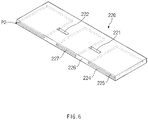
- FIG. 6 is a cross-sectional view taken along line B-B' of FIG. 5 .
- a can 130 for a secondary battery comprises a can body 110 that is opened to accommodate an electrode assembly 140 and a cover 220 which seals the opening of the can body 110 and through which an electrode lead passes, and the can body 110 comprises a body heat pipe that transfers heat generated in the electrode lead 147 to dissipate the heat through the can body 110 when the heat is transferred from the cover 220 to the can body 110.
- the can 230 for the secondary battery according to the second embodiment of the present invention is different from the can for the secondary battery according to the foregoing first embodiment of the prevent invention in that the can 230 further comprises a cover heat pipe P2 on the cover 220.
- contents duplicated with the can for the secondary battery according to the forgoing first embodiment of the present invention will be omitted or briefly described, and also, differences therebetween will be mainly described.
- the can body 110 may form an electrode assembly accommodation part 111, in which the electrode assembly 140 is accommodated, and may be opened to one side.
- the can body 110 may comprise the body heat pipe that transfers heat so that the heat is dissipated through the can body 110 when the heat generated in the electrode lead 147 is transferred from the cover 220 to an end of one end of the can body 110.
- the can body 110 may comprise an aluminum or copper material.
- the cover 220 may cover the end of the onside of the can body 110 to seal the opening, and through-holes 221 and 222, through which the electrode lead 147 of the electrode assembly 140 passes, may be formed in the cover 120.
- the cover 120 may comprise an aluminum or copper material.
- the cover 220 may comprise a cover heat pipe P2 that transfers heat so that the heat generated in the electrode lead 147 is dissipated through the cover 220.
- the cover heat pipe P2 may comprise an inner plate 224 disposed at a side of an electrode assembly accommodation part 111, an outer plate 225 spaced a predetermined distance from the inner plate 224, a partition part 226 disposed between the inner plate 224 and the outer plate 225 to partition a space between the inner plate 224 and the outer plate 225 so as to form a plurality of cover partition spaces 227, and a volatile heat medium that is accommodated in a cover partition space 227.
- the volatile heat medium accommodated in the cover partition space 227 may be made of at least one or more of acetone, water, freon, or ammonia.
- the cover partition space 227 in which the volatile heat medium is accommodated may be provided as a sealed vacuum space.
- the volatile heat medium may be acetone.
- the can 200 for the secondary battery according to the second embodiment of the present invention which is configured as described above, may be provided with the cover heat pipe P2 on the side of the cover 220 provided with the electrode lead 147, and thus, when peripheral portions of the through-holes 221 and 222 passing through the electrode lead 147 are heated by the electrode lead 147, heat may be easily transferred to the entire cover 220 and an upper end of the can body 110.
- the heat generated in the electrode lead 147 may be transferred to the cover 220 and the upper end of the can body 110, which is adjacent to the cover 220, and thus be quickly uniformly transferred to the entire can body 110 provided with the body heat pipe so as to be more effectively dissipated.
- a secondary battery 100 according to the first embodiment of the present invention comprises an electrode assembly 140 and a can 130 accommodating the electrode assembly 140.
- the can 130 comprises a can body 110 that is opened to accommodate an electrode assembly 140 and a cover 120 which seals the opening of the can body 110 and through which an electrode lead passes, and the can body 110 comprises a body heat pipe P1 that transfers heat generated in the electrode lead 147 to dissipate the heat through the can body 110 when the heat is transferred from the cover 120 to the can body 110.
- the secondary battery 100 according to the first embodiment of the present invention relates to a secondary battery 100 comprising the can 130 for the secondary battery according to the first embodiment of the present invention.
- contents duplicated with the can 130 for the secondary battery according to the first embodiment described above will be omitted or briefly described, and differences therebetween will be mainly described.
- the secondary battery 100 comprises the electrode assembly 140 and the can 130 accommodating the electrode assembly 140.
- the electrode assembly 140 may be a chargeable and dischargeable power generation element and may comprise electrodes 142 and separators 144, which are alternately stacked.
- the electrode assembly 140 may be provided in a wound form.
- the electrodes 142 may comprise a positive electrode 141 and a negative electrode 142.
- the electrode assembly 140 may have a structure in which the positive electrode 141/the separator 144/the negative electrode 142 are alternately laminated.
- the electrode lead 147 may comprise a positive electrode lead 145 connected to the positive electrode 141 and a negative electrode lead 146 connected to the negative electrode 142.
- the positive electrode 141 may comprise a positive electrode collector and a positive electrode active material stacked on the positive electrode collector.
- the positive electrode collector may be made of an aluminum foil.
- the positive electrode active material may comprise lithium manganese oxide, lithium cobalt oxide, lithium nickel oxide, lithium iron phosphate, or a compound or mixture containing at least one of the above-described materials.
- the negative electrode 142 may comprise a negative electrode collector and a negative electrode active material stacked on the negative electrode collector.
- the negative electrode collector may be made of, for example, a foil made of a copper (Cu) material.
- the negative active material may be a compound or a mixture containing a graphite-based material.
- the separator 144 is made of an insulation material to electrically insulate the positive electrode 141 from the negative electrode 142.
- the separator 144 may be made of a polyolefin-based resin film such as polyethylene or polypropylene having micropores.
- the can body 110 may form an electrode assembly accommodation part 111, in which the electrode assembly 140 is accommodated, and may be opened to one side.
- the can body 110 may comprise the body heat pipe P1 that transfers heat so that the heat is dissipated through the can body 110 when the heat generated in the electrode lead 147 is transferred from the cover 120 to an end of one end of the can body 110.
- the body heat pipe P1 comprises an inner wall 113 disposed at a side of the electrode assembly accommodation part 111, an outer wall 112 spaced a predetermined distance from the inner wall 113, a partition block 114 disposed between the inner wall 113 and the outer wall 112 to partition a space between the inner wall 113 and the outer wall 112 so as to form a plurality of body partition spaces 115, and a volatile heat medium that is accommodated in the body partition space 115.
- the body heat pipe P1 may be formed in any one or more of a plurality of columns or rows along a longitudinal direction of the can body 110.
- the body heat pipe P may be formed in a plurality of rows along the longitudinal direction of the can body 110.
- the partition block 114 may have one side provided on the inner wall 113 and the other side provided on the outer wall 112 in a width direction.
- the volatile heat medium may be made of at least one or more of acetone, water, freon, or ammonia.
- the body partition space 115 in which the volatile heat medium is accommodated may be provided as a sealed vacuum space.
- the cover 120 may cover the end of the onside of the can body 110 to seal the opening, and through-holes 121 and 122, through which the electrode lead 147 of the electrode assembly 140 passes, may be formed in the cover 120.
- a secondary battery 200 according to the second embodiment of the present invention comprises an electrode assembly 140 and a can 230 accommodating the electrode assembly 140.
- the can 230 comprises a can body 110 that is opened to accommodate an electrode assembly 140 and a cover 220 which seals the opening of the can body 110 and through which an electrode lead passes, and the can body 110 comprises a body heat pipe that transfers heat generated in the electrode lead 147 to dissipate the heat through the can body 110 when the heat is transferred from the cover 220 to the can body 110.
- the secondary battery 200 according to the second embodiment of the present invention relates to a secondary battery 200 comprising the can 230 for the secondary battery according to the forgoing second embodiment of the present invention.
- contents duplicated with the can 230 for the secondary battery according to the forgoing second embodiment of the present invention will be omitted or briefly described, and also, differences therebetween will be mainly described.
- the secondary battery 200 comprises the electrode assembly 140 and the can 230 accommodating the electrode assembly 140.
- the can body 110 may form an electrode assembly accommodation part 111, in which the electrode assembly 140 is accommodated, and may be opened to one side.
- the can body 110 may comprise the body heat pipe that transfers heat so that the heat is dissipated through the can body 110 when the heat generated in the electrode lead 147 is transferred from the cover 220 to an end of one end of the can body 110.
- the cover 220 may cover the end of the onside of the can body 110 to seal the opening, and through-holes 221 and 222, through which the electrode lead 147 of the electrode assembly 140 passes, may be formed in the cover 120.
- the cover 220 may comprise a cover heat pipe P2 that transfers heat so that the heat generated in the electrode lead 147 is dissipated through the cover 220.
- the cover heat pipe P2 may comprise an inner plate 224 disposed at a side of an electrode assembly accommodation part 111, an outer plate 225 spaced a predetermined distance from the inner plate 224, a partition part 226 disposed between the inner plate 224 and the outer plate 225 to partition a space between the inner plate 224 and the outer plate 225 so as to form a plurality of cover partition spaces 227, and a volatile heat medium that is accommodated in a cover partition space 227.
- the cover partition space 227 in which the volatile heat medium is accommodated may be provided as a sealed vacuum space.
Landscapes
- Chemical & Material Sciences (AREA)
- Chemical Kinetics & Catalysis (AREA)
- Electrochemistry (AREA)
- General Chemical & Material Sciences (AREA)
- Engineering & Computer Science (AREA)
- Manufacturing & Machinery (AREA)
- Inorganic Chemistry (AREA)
- Secondary Cells (AREA)
- Battery Mounting, Suspending (AREA)
- Sealing Battery Cases Or Jackets (AREA)
- Connection Of Batteries Or Terminals (AREA)
Abstract
Description
- The present application claims the benefit of the priority of
Korean Patent Application No. 10-2020-0030912, filed on March 12, 2020 - The present invention relates to a can for a secondary battery and a secondary battery.
- Secondary batteries are rechargeable unlike primarily batteries, and also, the possibility of compact size and high capacity is high. Thus, recently, many studies on secondary batteries are being carried out. As technology development and demands for mobile devices increase, the demands for secondary batteries as energy sources are rapidly increasing.
- Rechargeable batteries are classified into coin type batteries, cylindrical type batteries, prismatic type batteries, and pouch type batteries according to a shape of a battery case. The secondary battery accommodates an electrode assembly and an electrolyte. In such a secondary battery, an electrode assembly mounted in a battery case is a chargeable and dischargeable power generating device having a structure in which an electrode and a separator are stacked.
- The electrode assembly may be approximately classified into a jelly-roll type electrode assembly in which a separator is interposed between a positive electrode and a negative electrode, each of which is provided as the form of a sheet coated with an active material, and then, the positive electrode, the separator, and the negative electrode are wound, a stacked type electrode assembly in which a plurality of positive and negative electrodes with a separator therebetween are sequentially stacked, and a stack/folding type electrode assembly in which stacked type unit cells are wound together with a separation film having a long length.
- A cylindrical or prismatic battery according to the related art is constituted by an electrode assembly and a can accommodating the electrode assembly, and the can is constituted by a can body, in which an accommodation part is formed, and a cover covering the accommodation part.
- Here, the cover through which an electrode lead of the electrode assembly passes is heated by heat generated in the electrode lead, and thus, only an end of the can body, which is adjacent to the cover, may be locally heated.
- Thus, it has been difficult to dissipate the heat generated in the electrode lead.
- [Prior Art Document] (Patent Document 1)
Korean Patent Publication No. 10-2014-0015647 - One aspect of the present invention is to provide a can for a secondary battery, which is capable of uniformly distributing heat generated in a local region of a can to the can to dissipate the heat, and a secondary battery.
- A can for a secondary battery according to an embodiment of the present invention comprises: a can for a secondary battery and a secondary battery. The can for the secondary battery comprises a can body, in which an electrode assembly accommodation part accommodating an electrode assembly is formed, and which is opened to one side, and a cover which covers one end of the can body to seal an opening and in which a through-hole, through which an electrode lead of the electrode assembly passes, is formed, wherein the can body comprises a body heat pipe that transfers heat so that the heat is dissipated through the can body when the heat generated in the electrode lead is transferred from the cover to the can body.
- A secondary battery according to an embodiment of the present invention comprises: an electrode assembly; and a can, wherein the can comprises: a can body, in which an electrode assembly accommodation part is formed, and which is opened to one side; and a cover which covers one end of the can body to seal an opening and in which a through-hole, through which an electrode lead of the electrode assembly passes, is formed, wherein the can body comprises a body heat pipe that transfers heat so that the heat is dissipated through the can body when the heat generated in the electrode lead is transferred from the cover to the one end of the can body.
- According to the present invention, the heat may be uniformly distributed to the can body through a heat pipe, through which the heat is effectively transferred to the can body, to effectively dissipate the heat. Therefore, the heat dissipation efficiency may be improved to increase in battery lifespan and improve battery performance.
-
-
FIG. 1 is a perspective view illustrating a can for a secondary battery and a secondary battery comprising the can according to a first embodiment of the present invention. -
FIG. 2 is an exploded perspective view illustrating the can for the secondary battery and the secondary battery comprising the can according to the first embodiment of the present invention. -
FIG. 3 is a perspective view taken along line A-A' ofFIG. 2 . -
FIG. 4 is a perspective view illustrating a can for a secondary battery and a secondary battery comprising the can according to a second embodiment of the present invention. -
FIG. 5 is an exploded perspective view illustrating the can for the secondary battery and the secondary battery comprising the can according to the second embodiment of the present invention. -
FIG. 6 is a cross-sectional view taken along line B-B' ofFIG. 5 . - The objectives, specific advantages, and novel features of the present invention will become more apparent from the following detailed description taken in conjunction with the accompanying drawings. It should be noted that the reference numerals are added to the components of the drawings in the present specification with the same numerals as possible, even if they are illustrated in other drawings. Also, the present invention may be embodied in different forms and should not be construed as limited to the embodiments set forth herein. In the following description of the present invention, the detailed descriptions of related arts which may unnecessarily obscure the gist of the present invention will be omitted.
-
FIG. 1 is a perspective view illustrating a can for a secondary battery and a secondary battery comprising the can according to a first embodiment of the present invention,FIG. 2 is an exploded perspective view illustrating the can for the secondary battery and the secondary battery comprising the can according to the first embodiment of the present invention, andFIG. 3 is a perspective view taken along line A-A' ofFIG. 2 . - Referring to
FIGS. 1 to 3 , acan 130 for a secondary battery according to a first embodiment of the present invention comprises acan body 110 that is opened to accommodate anelectrode assembly 140 and acover 120 which seals the opening of thecan body 110 and through which an electrode lead passes, and thecan body 110 comprises a body heat pipe P1 that transfers heat generated in theelectrode lead 147 to dissipate the heat through thecan body 110 when the heat is transferred from thecover 120 to thecan body 110. - In more detail, the
can body 110 may form an electrodeassembly accommodation part 111, in which theelectrode assembly 140 is accommodated, and may be opened to one side. - Furthermore, the
can body 110 may comprise an aluminum or copper material. - Also, the
can body 110 may comprise the body heat pipe P1 that transfers heat so that the heat is dissipated through thecan body 110 when the heat generated in theelectrode lead 147 is transferred from thecover 120 to an end of one end of thecan body 110. - The body heat pipe P1 comprises an
inner wall 113 disposed at a side of the electrodeassembly accommodation part 111, anouter wall 112 spaced a predetermined distance from theinner wall 113, apartition block 114, which partitions a space between theinner wall 113 and theouter wall 112 to form a plurality ofbody partition spaces 115, and a volatile heat medium that is accommodated in thebody partition space 115. - The body heat pipe P1 may be formed in any one or more of a plurality of columns or rows along a longitudinal direction of the
can body 110. - Here, for example, the body heat pipe P may be formed in a plurality of rows along the longitudinal direction of the
can body 110. - The
partition block 114 may have one side provided on theinner wall 113 and the other side provided on theouter wall 112 in a width direction. - The volatile heat medium may be vaporized to effectively transfer heat when the volatile heat medium is heated.
- Here, the volatile heat medium may be made of at least one or more of acetone, water, freon, or ammonia.
- The
body partition space 115 in which the volatile heat medium is accommodated may be provided as a sealed vacuum space. Also, the body partition space may be formed along the longitudinal direction of thecan body 110 so that the volatile heat medium accommodated in thebody partition space 115 easily transfers the heat along the longitudinal direction of thecan body 110. Here, when an upper end of thecan body 110, which is in contact with thecover 120, is heated through thecover 120 due to the generation of heat in theelectrode lead 147, the heat may be effectively transferred up to a lower portion of thecan body 110 to easily dissipate the heat through thecan body 110. - The
cover 120 may cover the end of the onside of thecan body 110 to seal the opening, and through-holes electrode assembly 140 passes, may be formed in thecover 120. Here, a lower edge of thecover 120 may be coupled or fixed to an upper end of thecan body 110. - Also, the
cover 120 may be formed in a rectangular or circular plate shape. - Also, the
cover 120 may comprise an aluminum or copper material. - Here, when each of the
can body 110 and thecover 120 comprises the aluminum material, the volatile heat medium may be acetone. - In the
cover 120, an insulator may be disposed between theelectrode lead 147 and each of the through-holes electrode lead 147 and thecover 120 from each other. - Also, an outer surface of each of the
can body 110 and thecover 120 may be wrapped with the insulator to insulate thecan 130 from the outside. - The
can 100 for the secondary battery according to the first embodiment may further comprise thermal grease applied to the outer surface of thecan body 110. Thus, thecan body 110 may increase in thermal conductivity to improve a heat dissipation effect. - In the
can 100 for the secondary battery according to the first embodiment of the present invention, which is configured as described above, the heat generated at a side of the cover provided with theelectrode lead 147 may be effectively dissipated through thecan body 110 provided with the body heat pipe P1. That is, when thecover 120 and the upper end of thecan body 110, which is adjacent to thecover 120, are heated, the heat may be uniformly transferred to theentire can body 110 through the body heat pipe P1 provided on thecan body 110 to realize the effective heat dissipation. Furthermore, even if heat is generated not only at the upper end of thecan body 110 but also at other local portions of thecan body 110, the heat may be uniformly effectively distributed to theentire can body 110 through the body heat pipe P and thus be effectively dissipated. Therefore, the heat dissipation efficiency may be improved to increase in battery lifespan and improve battery performance. - In addition, since the
can body 110 is provided in a heat dissipation structure comprising the body heat pipe PI, it is not necessary to install a separate heat dissipation device, thereby securing flexibility in space utilization. Thus, when compared to a secondary battery or battery pack having the same size, it may have a remarkably high energy density. In addition, since the number of components for the heat dissipation decreases, the number of assembly processes may decrease to improve productivity. Here, according to the related art, heat dissipation is realized only when a heat transfer process is performed through a structure constituted by a cell, a cartridge, and a heat dissipation plate. On the other hand, according to the present invention, the structure for dissipating heat through the heat transfer process using theelectrode assembly 140 and thecan 130 comprising the body heat pipe P1 may be provided to reduce the number of component for the heat dissipation. - Furthermore, the heat pipe manner, in which the inner and outer surfaces of the
can 130 are formed, and the partition space is formed therein, and then, the volatile liquid is put to make a vacuum state, thereby quickly transferring heat, according to the present invention may be applied to thecan 130 having a thin thickness to increase in space that is occupied by theelectrode assembly 140, thereby improving the energy density. However, for example, when the heat radiation grease or heat radiation pad is put in the partition space, thecan 130 may increase in thickness. As a result, the space that is occupied by the electrode assembly may be reduced to deteriorate the energy efficiency. In addition, since thecan 130 is designed to have the thin thickness, it may be difficult to apply the technology of putting the heat dissipation grease or heat dissipation pad in the partition space. - Hereinafter, a can for a secondary battery according to a second embodiment of the present invention will be described.
-
FIG. 4 is a perspective view illustrating a can for a secondary battery and a secondary battery comprising the can according to a second embodiment of the present invention,FIG. 5 is an exploded perspective view illustrating the can for the secondary battery and the secondary battery comprising the can according to the first embodiment of the present invention, andFIG. 6 is a cross-sectional view taken along line B-B' ofFIG. 5 . - Referring to
FIGS. 4 to 6 , a can 130 for a secondary battery according to a second embodiment of the present invention comprises acan body 110 that is opened to accommodate anelectrode assembly 140 and acover 220 which seals the opening of thecan body 110 and through which an electrode lead passes, and thecan body 110 comprises a body heat pipe that transfers heat generated in theelectrode lead 147 to dissipate the heat through thecan body 110 when the heat is transferred from thecover 220 to thecan body 110. - The can 230 for the secondary battery according to the second embodiment of the present invention is different from the can for the secondary battery according to the foregoing first embodiment of the prevent invention in that the
can 230 further comprises a cover heat pipe P2 on thecover 220. Thus, in description of thecan 230 for the secondary battery according to this embodiment, contents duplicated with the can for the secondary battery according to the forgoing first embodiment of the present invention will be omitted or briefly described, and also, differences therebetween will be mainly described. - In more detail, the
can body 110 may form an electrodeassembly accommodation part 111, in which theelectrode assembly 140 is accommodated, and may be opened to one side. - Also, the
can body 110 may comprise the body heat pipe that transfers heat so that the heat is dissipated through thecan body 110 when the heat generated in theelectrode lead 147 is transferred from thecover 220 to an end of one end of thecan body 110. - Furthermore, the
can body 110 may comprise an aluminum or copper material. - The
cover 220 may cover the end of the onside of thecan body 110 to seal the opening, and through-holes electrode lead 147 of theelectrode assembly 140 passes, may be formed in thecover 120. - Also, the
cover 120 may comprise an aluminum or copper material. - Furthermore, the
cover 220 may comprise a cover heat pipe P2 that transfers heat so that the heat generated in theelectrode lead 147 is dissipated through thecover 220. - The cover heat pipe P2 may comprise an inner plate 224 disposed at a side of an electrode
assembly accommodation part 111, anouter plate 225 spaced a predetermined distance from the inner plate 224, apartition part 226 disposed between the inner plate 224 and theouter plate 225 to partition a space between the inner plate 224 and theouter plate 225 so as to form a plurality ofcover partition spaces 227, and a volatile heat medium that is accommodated in acover partition space 227. - Here, the volatile heat medium accommodated in the
cover partition space 227 may be made of at least one or more of acetone, water, freon, or ammonia. - The
cover partition space 227 in which the volatile heat medium is accommodated may be provided as a sealed vacuum space. - Here, when each of the
can body 110 and thecover 220 comprises the aluminum material, the volatile heat medium may be acetone. - The can 200 for the secondary battery according to the second embodiment of the present invention, which is configured as described above, may be provided with the cover heat pipe P2 on the side of the
cover 220 provided with theelectrode lead 147, and thus, when peripheral portions of the through-holes electrode lead 147 are heated by theelectrode lead 147, heat may be easily transferred to theentire cover 220 and an upper end of thecan body 110. - Thus, the heat generated in the
electrode lead 147 may be transferred to thecover 220 and the upper end of thecan body 110, which is adjacent to thecover 220, and thus be quickly uniformly transferred to theentire can body 110 provided with the body heat pipe so as to be more effectively dissipated. - Hereinafter, the secondary battery according to the first embodiment of the present invention will be described.
- Referring to
FIGS. 1 to 3 , asecondary battery 100 according to the first embodiment of the present invention comprises anelectrode assembly 140 and a can 130 accommodating theelectrode assembly 140. The can 130 comprises acan body 110 that is opened to accommodate anelectrode assembly 140 and acover 120 which seals the opening of thecan body 110 and through which an electrode lead passes, and thecan body 110 comprises a body heat pipe P1 that transfers heat generated in theelectrode lead 147 to dissipate the heat through thecan body 110 when the heat is transferred from thecover 120 to thecan body 110. - The
secondary battery 100 according to the first embodiment of the present invention relates to asecondary battery 100 comprising thecan 130 for the secondary battery according to the first embodiment of the present invention. Thus, in description of thesecondary battery 100 according to the first embodiment, contents duplicated with thecan 130 for the secondary battery according to the first embodiment described above will be omitted or briefly described, and differences therebetween will be mainly described. - In more detail, the
secondary battery 100 comprises theelectrode assembly 140 and thecan 130 accommodating theelectrode assembly 140. - The
electrode assembly 140 may be a chargeable and dischargeable power generation element and may compriseelectrodes 142 andseparators 144, which are alternately stacked. Here, theelectrode assembly 140 may be provided in a wound form. - The
electrodes 142 may comprise apositive electrode 141 and anegative electrode 142. Here, theelectrode assembly 140 may have a structure in which thepositive electrode 141/theseparator 144/thenegative electrode 142 are alternately laminated. Also, theelectrode lead 147 may comprise apositive electrode lead 145 connected to thepositive electrode 141 and anegative electrode lead 146 connected to thenegative electrode 142. - The
positive electrode 141 may comprise a positive electrode collector and a positive electrode active material stacked on the positive electrode collector. - The positive electrode collector may be made of an aluminum foil.
- The positive electrode active material may comprise lithium manganese oxide, lithium cobalt oxide, lithium nickel oxide, lithium iron phosphate, or a compound or mixture containing at least one of the above-described materials.
- The
negative electrode 142 may comprise a negative electrode collector and a negative electrode active material stacked on the negative electrode collector. - The negative electrode collector may be made of, for example, a foil made of a copper (Cu) material.
- The negative active material may be a compound or a mixture containing a graphite-based material.
- The
separator 144 is made of an insulation material to electrically insulate thepositive electrode 141 from thenegative electrode 142. Here, theseparator 144 may be made of a polyolefin-based resin film such as polyethylene or polypropylene having micropores. - The
can body 110 may form an electrodeassembly accommodation part 111, in which theelectrode assembly 140 is accommodated, and may be opened to one side. - Also, the
can body 110 may comprise the body heat pipe P1 that transfers heat so that the heat is dissipated through thecan body 110 when the heat generated in theelectrode lead 147 is transferred from thecover 120 to an end of one end of thecan body 110. - The body heat pipe P1 comprises an
inner wall 113 disposed at a side of the electrodeassembly accommodation part 111, anouter wall 112 spaced a predetermined distance from theinner wall 113, apartition block 114 disposed between theinner wall 113 and theouter wall 112 to partition a space between theinner wall 113 and theouter wall 112 so as to form a plurality ofbody partition spaces 115, and a volatile heat medium that is accommodated in thebody partition space 115. - The body heat pipe P1 may be formed in any one or more of a plurality of columns or rows along a longitudinal direction of the
can body 110. Here, for example, the body heat pipe P may be formed in a plurality of rows along the longitudinal direction of thecan body 110. - The
partition block 114 may have one side provided on theinner wall 113 and the other side provided on theouter wall 112 in a width direction. - The volatile heat medium may be made of at least one or more of acetone, water, freon, or ammonia.
- The
body partition space 115 in which the volatile heat medium is accommodated may be provided as a sealed vacuum space. - The
cover 120 may cover the end of the onside of thecan body 110 to seal the opening, and through-holes electrode lead 147 of theelectrode assembly 140 passes, may be formed in thecover 120. - Hereinafter, a secondary battery according to a second embodiment of the present invention will be described.
- Referring to
FIGS. 4 to 6 , asecondary battery 200 according to the second embodiment of the present invention comprises anelectrode assembly 140 and a can 230 accommodating theelectrode assembly 140. The can 230 comprises acan body 110 that is opened to accommodate anelectrode assembly 140 and acover 220 which seals the opening of thecan body 110 and through which an electrode lead passes, and thecan body 110 comprises a body heat pipe that transfers heat generated in theelectrode lead 147 to dissipate the heat through thecan body 110 when the heat is transferred from thecover 220 to thecan body 110. - The
secondary battery 200 according to the second embodiment of the present invention relates to asecondary battery 200 comprising thecan 230 for the secondary battery according to the forgoing second embodiment of the present invention. Thus, in description of thesecondary battery 200 according to this embodiment, contents duplicated with thecan 230 for the secondary battery according to the forgoing second embodiment of the present invention will be omitted or briefly described, and also, differences therebetween will be mainly described. - In more detail, the
secondary battery 200 comprises theelectrode assembly 140 and thecan 230 accommodating theelectrode assembly 140. - The
can body 110 may form an electrodeassembly accommodation part 111, in which theelectrode assembly 140 is accommodated, and may be opened to one side. - Also, the
can body 110 may comprise the body heat pipe that transfers heat so that the heat is dissipated through thecan body 110 when the heat generated in theelectrode lead 147 is transferred from thecover 220 to an end of one end of thecan body 110. - The
cover 220 may cover the end of the onside of thecan body 110 to seal the opening, and through-holes electrode lead 147 of theelectrode assembly 140 passes, may be formed in thecover 120. - In addition, the
cover 220 may comprise a cover heat pipe P2 that transfers heat so that the heat generated in theelectrode lead 147 is dissipated through thecover 220. - The cover heat pipe P2 may comprise an inner plate 224 disposed at a side of an electrode
assembly accommodation part 111, anouter plate 225 spaced a predetermined distance from the inner plate 224, apartition part 226 disposed between the inner plate 224 and theouter plate 225 to partition a space between the inner plate 224 and theouter plate 225 so as to form a plurality ofcover partition spaces 227, and a volatile heat medium that is accommodated in acover partition space 227. - The
cover partition space 227 in which the volatile heat medium is accommodated may be provided as a sealed vacuum space. - While the present invention has been particularly shown and described with reference to the specific embodiments thereof, the can for the secondary battery and the secondary battery according to the present invention are not limited thereto. It will be understood by those of ordinary skill in the art that various changes in form and details may be made therein without departing from the spirit and scope of the present invention.
- Furthermore, the scope of protection of the present invention will be clarified by the appended claims.
-
- 100, 200: Secondary battery
- 110: Can body
- 111: Electrode assembly accommodation part
- 112: Outer wall
- 113: Inner wall
- 114: Partition block
- 115: Body partition space
- 120, 220: Cover
- 121, 122, 221, 222: Through-hole
- 130, 230: Can
- 140: Electrode assembly
- 141: Positive electrode
- 142: Negative electrode
- 143: Electrode
- 144: Separator
- 145: Positive electrode lead
- 146: Negative electrode lead
- 147: Electrode lead
- 224: Inner plate
- 225: Outer plate
- 226: Partition part
- 227: Cover partition space
- PI: Body heat pipe
- P2: Cover heat pipe
Claims (12)
- A can for a secondary battery, comprising:a can body, in which an electrode assembly accommodation part accommodating an electrode assembly is formed, and which is opened to one side; anda cover which covers one end of the can body to seal an opening and in which a through-hole, through which an electrode lead of the electrode assembly passes, is formed,wherein the can body comprises a body heat pipe that transfers heat.
- The can for the secondary battery of claim 1, wherein, when heat generated in the electrode lead is transferred from the cover to the can body, the body heat pipe transfers the heat to dissipate the heat through the can body.
- The can for the secondary battery of claim 1, wherein the can body receives the heat generated in the electrode lead from the cover to dissipate the heat.
- The can for the secondary battery of claim 1, wherein the body heat pipe comprises:an inner wall disposed at a side of the electrode assembly accommodation part;an outer wall spaced a predetermined distance from the inner wall;a partition block disposed between the inner wall and the outer wall to partition a space between the inner wall and the outer wall so as to form a plurality of body partition spaces; anda volatile heat medium accommodated in the body partition space.
- The can for the secondary battery of claim 4, wherein the body heat pipe is formed in any one or more of a plurality of columns or rows along a longitudinal direction of the can body.
- The can for the secondary battery of claim 4, wherein the partition block has one side provided at the inner wall and the other side provided at the outer wall in a width direction thereof.
- The can for the secondary battery of claim 4, wherein the cover comprises a cover heat pipe that transfers heat so that the heat generated in the electrode lead is dissipated through the cover.
- The can for the secondary battery of claim 7, wherein the cover heat pipe comprises:an inner plate disposed at a side of the electrode assembly accommodation part;an outer plate spaced a predetermined distance from the inner plate;a partition part disposed between the inner plate and the outer plate to partition a space between the inner plate and the outer plate so as to form a plurality of cover partition spaces; anda volatile heat medium that is accommodated in a cover partition space.
- The can for the secondary battery of claim 8, wherein the volatile heat medium is made of at least one or more of acetone, water, freon, or ammonia.
- The can for the secondary battery of claim 9, wherein each of the body and cover partition spaces, in which the volatile heat medium is accommodated, is a vacuum space that is sealed.
- The can for the secondary battery of claim 8, wherein each of the can body and the cover comprises an aluminum or copper material.
- A secondary battery comprising:an electrode assembly; anda can,wherein the can comprises:a can body, in which an electrode assembly accommodation part is formed, and which is opened to one side; anda cover which covers one end of the can body to seal an opening and in which a through-hole, through which an electrode lead of the electrode assembly passes, is formed,wherein the can body comprises a body heat pipe that transfers heat so that the heat is dissipated through the can body when the heat generated in the electrode lead is transferred from the cover to the one end of the can body.
Applications Claiming Priority (2)
| Application Number | Priority Date | Filing Date | Title |
|---|---|---|---|
| KR1020200030912A KR102868802B1 (en) | 2020-03-12 | 2020-03-12 | Can for rechargeable battery and rechargeable battery |
| PCT/KR2021/002846 WO2021182823A1 (en) | 2020-03-12 | 2021-03-08 | Can for secondary battery, and secondary battery |
Publications (3)
| Publication Number | Publication Date |
|---|---|
| EP4089798A1 true EP4089798A1 (en) | 2022-11-16 |
| EP4089798A4 EP4089798A4 (en) | 2024-05-22 |
| EP4089798B1 EP4089798B1 (en) | 2025-05-21 |
Family
ID=77670854
Family Applications (1)
| Application Number | Title | Priority Date | Filing Date |
|---|---|---|---|
| EP21767252.6A Active EP4089798B1 (en) | 2020-03-12 | 2021-03-08 | Can for secondary battery, and secondary battery |
Country Status (8)
| Country | Link |
|---|---|
| US (1) | US12451535B2 (en) |
| EP (1) | EP4089798B1 (en) |
| JP (1) | JP7540842B2 (en) |
| KR (1) | KR102868802B1 (en) |
| CN (1) | CN115066787A (en) |
| ES (1) | ES3034282T3 (en) |
| HU (1) | HUE072387T2 (en) |
| WO (1) | WO2021182823A1 (en) |
Family Cites Families (34)
| Publication number | Priority date | Publication date | Assignee | Title |
|---|---|---|---|---|
| JP2000173664A (en) | 1998-12-10 | 2000-06-23 | Asahi Chem Ind Co Ltd | Power source device |
| KR100300428B1 (en) | 1999-05-06 | 2001-09-26 | 김순택 | Secondary battery |
| JP2001196103A (en) * | 2000-01-12 | 2001-07-19 | Matsushita Electric Ind Co Ltd | Battery cooling structure |
| KR100635775B1 (en) | 2004-10-28 | 2006-10-17 | 삼성에스디아이 주식회사 | Secondary battery |
| KR100648698B1 (en) | 2005-03-25 | 2006-11-23 | 삼성에스디아이 주식회사 | Secondary battery module |
| KR100728126B1 (en) | 2005-11-15 | 2007-06-13 | 삼성에스디아이 주식회사 | Secondary battery |
| KR100717801B1 (en) | 2005-12-19 | 2007-05-11 | 삼성에스디아이 주식회사 | Secondary battery |
| JP4839955B2 (en) * | 2006-05-11 | 2011-12-21 | トヨタ自動車株式会社 | Battery pack and vehicle |
| JP5173346B2 (en) | 2007-10-15 | 2013-04-03 | 三洋電機株式会社 | Power supply |
| US8216713B2 (en) | 2009-02-25 | 2012-07-10 | Sb Limotive Co., Ltd. | Battery housing formed with cooling passages and battery pack having the same |
| DE102009016867A1 (en) | 2009-04-08 | 2010-10-14 | Li-Tec Battery Gmbh | Accumulator with extended life |
| KR101057558B1 (en) | 2010-01-27 | 2011-08-17 | 에스비리모티브 주식회사 | Battery pack |
| KR20110118807A (en) | 2010-01-29 | 2011-11-01 | 파나소닉 주식회사 | Battery module |
| US8435668B2 (en) | 2010-07-23 | 2013-05-07 | GM Global Technology Operations LLC | Prismatic battery cell with integrated cooling passages and assembly frame |
| US20130149586A1 (en) | 2011-12-09 | 2013-06-13 | Samsung Sdi Co., Ltd. | Battery cell |
| KR101370144B1 (en) | 2012-01-25 | 2014-03-28 | (주)벡셀 | Square lithium type cell |
| KR101528001B1 (en) | 2012-06-22 | 2015-06-10 | 주식회사 엘지화학 | Electrode assembly, manufacture thereof, and secondary batteries including same |
| DE102012212451A1 (en) | 2012-07-17 | 2014-02-06 | Robert Bosch Gmbh | Cell for battery e.g. lithium ion battery utilized as energy storage for supplying power for headlight of electrical vehicle, has heat conducting element arranged in interior region and integrated into sleeve to accept heat distribution |
| CN203056025U (en) | 2012-07-21 | 2013-07-10 | 浙江南博电源科技有限公司 | High-capacity square lithium ion battery |
| KR101658961B1 (en) | 2013-09-23 | 2016-09-22 | 주식회사 엘지화학 | Pouch type secondary battery |
| KR101767633B1 (en) | 2014-10-07 | 2017-08-11 | 주식회사 엘지화학 | Battery Module |
| KR101766687B1 (en) | 2015-10-19 | 2017-08-09 | 주식회사 엘지엠 | Battery case system having good heating and cooling |
| DE102016200088A1 (en) * | 2016-01-07 | 2017-07-13 | Robert Bosch Gmbh | Battery module housing, battery module, and method of making a battery module housing |
| KR102188726B1 (en) * | 2016-09-02 | 2020-12-08 | 주식회사 엘지화학 | Electrode assembly |
| KR102053842B1 (en) * | 2016-10-14 | 2019-12-09 | 주식회사 엘지화학 | Secondary battery including electrode lead |
| KR102133554B1 (en) | 2016-10-21 | 2020-07-13 | 주식회사 엘지화학 | Battery pack |
| KR102242246B1 (en) * | 2016-12-21 | 2021-04-20 | 주식회사 엘지화학 | Secondary battery and method of manufacturing the same |
| CN108987844B (en) * | 2017-05-31 | 2021-06-18 | 比亚迪股份有限公司 | A battery and battery module |
| CN107634161A (en) | 2017-09-07 | 2018-01-26 | 河南新太行电源股份有限公司 | Battery case and battery with radiating tube |
| CN207217601U (en) | 2017-09-15 | 2018-04-10 | 河南新太行电源股份有限公司 | A kind of battery case and battery with heat radiation sandwich layer |
| KR20190107478A (en) | 2018-03-12 | 2019-09-20 | 현대모비스 주식회사 | Water cooling battery module |
| JP7004168B2 (en) | 2018-04-20 | 2022-01-21 | マツダ株式会社 | Vehicle power storage device |
| CN208723021U (en) | 2018-06-28 | 2019-04-09 | 华南理工大学 | It is a kind of can be from the internal thermally conductive lithium ion battery to radiate |
| JP7546608B2 (en) | 2019-06-13 | 2024-09-06 | 耀華 趙 | Thermal management system and method for lithium battery pack |
-
2020
- 2020-03-12 KR KR1020200030912A patent/KR102868802B1/en active Active
-
2021
- 2021-03-08 US US17/798,445 patent/US12451535B2/en active Active
- 2021-03-08 JP JP2022552471A patent/JP7540842B2/en active Active
- 2021-03-08 HU HUE21767252A patent/HUE072387T2/en unknown
- 2021-03-08 CN CN202180012919.0A patent/CN115066787A/en active Pending
- 2021-03-08 ES ES21767252T patent/ES3034282T3/en active Active
- 2021-03-08 EP EP21767252.6A patent/EP4089798B1/en active Active
- 2021-03-08 WO PCT/KR2021/002846 patent/WO2021182823A1/en not_active Ceased
Also Published As
| Publication number | Publication date |
|---|---|
| EP4089798B1 (en) | 2025-05-21 |
| ES3034282T3 (en) | 2025-08-14 |
| JP2023515656A (en) | 2023-04-13 |
| WO2021182823A1 (en) | 2021-09-16 |
| KR102868802B1 (en) | 2025-10-10 |
| HUE072387T2 (en) | 2025-11-28 |
| CN115066787A (en) | 2022-09-16 |
| EP4089798A4 (en) | 2024-05-22 |
| JP7540842B2 (en) | 2024-08-27 |
| KR20210115324A (en) | 2021-09-27 |
| US12451535B2 (en) | 2025-10-21 |
| US20230066959A1 (en) | 2023-03-02 |
Similar Documents
| Publication | Publication Date | Title |
|---|---|---|
| US10804578B2 (en) | Battery module, battery pack and vehicle having same | |
| US8551631B2 (en) | Assembled battery, and vehicle equipped with the assembled battery | |
| JP7566281B2 (en) | Battery module and battery pack including same | |
| KR102058194B1 (en) | battery module | |
| KR102051109B1 (en) | Battery Module | |
| JP2011503793A (en) | Battery cell with improved thermal stability and medium- or large-sized battery module using the same | |
| JP2008282648A (en) | Assembled battery | |
| EP4037068A1 (en) | Electrode assembly and secondary battery comprising same | |
| EP4181275B1 (en) | Battery module and battery pack including same | |
| US9502733B2 (en) | Electrode assembly and secondary battery having the same | |
| EP4089798B1 (en) | Can for secondary battery, and secondary battery | |
| EP3355380A1 (en) | Battery housing with absorbent and insulator | |
| JP2023510897A (en) | Battery modules and battery packs containing the same | |
| US20250140975A1 (en) | Battery Module and Battery Pack Including the Same | |
| KR20240166667A (en) | Battery Pack | |
| KR102751361B1 (en) | Secondary battery and a secondary battery module including the same | |
| EP4528913A1 (en) | Secondary battery | |
| KR102922216B1 (en) | Rechargeable battery | |
| KR102260389B1 (en) | Secondary Battery Cell having Improved Cooling Performance and Secondary Battery module having plurality of the Secondary Battery Cells | |
| EP4376141A1 (en) | Battery module and battery pack including same | |
| EP4175020A1 (en) | Battery module and battery pack including same | |
| KR20250122181A (en) | Battery cell and battery module including the same | |
| EP3333940B1 (en) | Secondary battery | |
| JP2026001254A (en) | Energy storage module | |
| KR20240127159A (en) | Battery device comprising heat sink |
Legal Events
| Date | Code | Title | Description |
|---|---|---|---|
| STAA | Information on the status of an ep patent application or granted ep patent |
Free format text: STATUS: THE INTERNATIONAL PUBLICATION HAS BEEN MADE |
|
| PUAI | Public reference made under article 153(3) epc to a published international application that has entered the european phase |
Free format text: ORIGINAL CODE: 0009012 |
|
| STAA | Information on the status of an ep patent application or granted ep patent |
Free format text: STATUS: REQUEST FOR EXAMINATION WAS MADE |
|
| 17P | Request for examination filed |
Effective date: 20220811 |
|
| AK | Designated contracting states |
Kind code of ref document: A1 Designated state(s): AL AT BE BG CH CY CZ DE DK EE ES FI FR GB GR HR HU IE IS IT LI LT LU LV MC MK MT NL NO PL PT RO RS SE SI SK SM TR |
|
| DAV | Request for validation of the european patent (deleted) | ||
| DAX | Request for extension of the european patent (deleted) | ||
| A4 | Supplementary search report drawn up and despatched |
Effective date: 20240422 |
|
| RIC1 | Information provided on ipc code assigned before grant |
Ipc: H01M 50/103 20210101ALI20240416BHEP Ipc: H01M 10/647 20140101ALI20240416BHEP Ipc: H01M 10/6552 20140101AFI20240416BHEP |
|
| GRAP | Despatch of communication of intention to grant a patent |
Free format text: ORIGINAL CODE: EPIDOSNIGR1 |
|
| STAA | Information on the status of an ep patent application or granted ep patent |
Free format text: STATUS: GRANT OF PATENT IS INTENDED |
|
| GRAJ | Information related to disapproval of communication of intention to grant by the applicant or resumption of examination proceedings by the epo deleted |
Free format text: ORIGINAL CODE: EPIDOSDIGR1 |
|
| STAA | Information on the status of an ep patent application or granted ep patent |
Free format text: STATUS: REQUEST FOR EXAMINATION WAS MADE |
|
| GRAP | Despatch of communication of intention to grant a patent |
Free format text: ORIGINAL CODE: EPIDOSNIGR1 |
|
| STAA | Information on the status of an ep patent application or granted ep patent |
Free format text: STATUS: GRANT OF PATENT IS INTENDED |
|
| INTG | Intention to grant announced |
Effective date: 20250113 |
|
| INTG | Intention to grant announced |
Effective date: 20250120 |
|
| P01 | Opt-out of the competence of the unified patent court (upc) registered |
Free format text: CASE NUMBER: APP_6059/2025 Effective date: 20250205 |
|
| GRAS | Grant fee paid |
Free format text: ORIGINAL CODE: EPIDOSNIGR3 |
|
| GRAA | (expected) grant |
Free format text: ORIGINAL CODE: 0009210 |
|
| STAA | Information on the status of an ep patent application or granted ep patent |
Free format text: STATUS: THE PATENT HAS BEEN GRANTED |
|
| AK | Designated contracting states |
Kind code of ref document: B1 Designated state(s): AL AT BE BG CH CY CZ DE DK EE ES FI FR GB GR HR HU IE IS IT LI LT LU LV MC MK MT NL NO PL PT RO RS SE SI SK SM TR |
|
| REG | Reference to a national code |
Ref country code: GB Ref legal event code: FG4D |
|
| REG | Reference to a national code |
Ref country code: CH Ref legal event code: EP |
|
| REG | Reference to a national code |
Ref country code: DE Ref legal event code: R096 Ref document number: 602021031175 Country of ref document: DE |
|
| REG | Reference to a national code |
Ref country code: IE Ref legal event code: FG4D |
|
| REG | Reference to a national code |
Ref country code: ES Ref legal event code: FG2A Ref document number: 3034282 Country of ref document: ES Kind code of ref document: T3 Effective date: 20250814 |
|
| REG | Reference to a national code |
Ref country code: NL Ref legal event code: MP Effective date: 20250521 |
|
| PG25 | Lapsed in a contracting state [announced via postgrant information from national office to epo] |
Ref country code: PT Free format text: LAPSE BECAUSE OF FAILURE TO SUBMIT A TRANSLATION OF THE DESCRIPTION OR TO PAY THE FEE WITHIN THE PRESCRIBED TIME-LIMIT Effective date: 20250922 Ref country code: FI Free format text: LAPSE BECAUSE OF FAILURE TO SUBMIT A TRANSLATION OF THE DESCRIPTION OR TO PAY THE FEE WITHIN THE PRESCRIBED TIME-LIMIT Effective date: 20250521 |
|
| REG | Reference to a national code |
Ref country code: LT Ref legal event code: MG9D |
|
| PG25 | Lapsed in a contracting state [announced via postgrant information from national office to epo] |
Ref country code: GR Free format text: LAPSE BECAUSE OF FAILURE TO SUBMIT A TRANSLATION OF THE DESCRIPTION OR TO PAY THE FEE WITHIN THE PRESCRIBED TIME-LIMIT Effective date: 20250822 Ref country code: NO Free format text: LAPSE BECAUSE OF FAILURE TO SUBMIT A TRANSLATION OF THE DESCRIPTION OR TO PAY THE FEE WITHIN THE PRESCRIBED TIME-LIMIT Effective date: 20250821 |
|
| PG25 | Lapsed in a contracting state [announced via postgrant information from national office to epo] |
Ref country code: PL Free format text: LAPSE BECAUSE OF FAILURE TO SUBMIT A TRANSLATION OF THE DESCRIPTION OR TO PAY THE FEE WITHIN THE PRESCRIBED TIME-LIMIT Effective date: 20250521 Ref country code: NL Free format text: LAPSE BECAUSE OF FAILURE TO SUBMIT A TRANSLATION OF THE DESCRIPTION OR TO PAY THE FEE WITHIN THE PRESCRIBED TIME-LIMIT Effective date: 20250521 |
|
| PG25 | Lapsed in a contracting state [announced via postgrant information from national office to epo] |
Ref country code: BG Free format text: LAPSE BECAUSE OF FAILURE TO SUBMIT A TRANSLATION OF THE DESCRIPTION OR TO PAY THE FEE WITHIN THE PRESCRIBED TIME-LIMIT Effective date: 20250521 |
|
| PG25 | Lapsed in a contracting state [announced via postgrant information from national office to epo] |
Ref country code: HR Free format text: LAPSE BECAUSE OF FAILURE TO SUBMIT A TRANSLATION OF THE DESCRIPTION OR TO PAY THE FEE WITHIN THE PRESCRIBED TIME-LIMIT Effective date: 20250521 |
|
| PG25 | Lapsed in a contracting state [announced via postgrant information from national office to epo] |
Ref country code: RS Free format text: LAPSE BECAUSE OF FAILURE TO SUBMIT A TRANSLATION OF THE DESCRIPTION OR TO PAY THE FEE WITHIN THE PRESCRIBED TIME-LIMIT Effective date: 20250821 |
|
| PG25 | Lapsed in a contracting state [announced via postgrant information from national office to epo] |
Ref country code: IS Free format text: LAPSE BECAUSE OF FAILURE TO SUBMIT A TRANSLATION OF THE DESCRIPTION OR TO PAY THE FEE WITHIN THE PRESCRIBED TIME-LIMIT Effective date: 20250921 |
|
| PG25 | Lapsed in a contracting state [announced via postgrant information from national office to epo] |
Ref country code: LV Free format text: LAPSE BECAUSE OF FAILURE TO SUBMIT A TRANSLATION OF THE DESCRIPTION OR TO PAY THE FEE WITHIN THE PRESCRIBED TIME-LIMIT Effective date: 20250521 |
|
| REG | Reference to a national code |
Ref country code: HU Ref legal event code: AG4A Ref document number: E072387 Country of ref document: HU |
|
| REG | Reference to a national code |
Ref country code: AT Ref legal event code: MK05 Ref document number: 1797595 Country of ref document: AT Kind code of ref document: T Effective date: 20250521 |
|
| PG25 | Lapsed in a contracting state [announced via postgrant information from national office to epo] |
Ref country code: DK Free format text: LAPSE BECAUSE OF FAILURE TO SUBMIT A TRANSLATION OF THE DESCRIPTION OR TO PAY THE FEE WITHIN THE PRESCRIBED TIME-LIMIT Effective date: 20250521 Ref country code: AT Free format text: LAPSE BECAUSE OF FAILURE TO SUBMIT A TRANSLATION OF THE DESCRIPTION OR TO PAY THE FEE WITHIN THE PRESCRIBED TIME-LIMIT Effective date: 20250521 Ref country code: SM Free format text: LAPSE BECAUSE OF FAILURE TO SUBMIT A TRANSLATION OF THE DESCRIPTION OR TO PAY THE FEE WITHIN THE PRESCRIBED TIME-LIMIT Effective date: 20250521 |
|
| PG25 | Lapsed in a contracting state [announced via postgrant information from national office to epo] |
Ref country code: CZ Free format text: LAPSE BECAUSE OF FAILURE TO SUBMIT A TRANSLATION OF THE DESCRIPTION OR TO PAY THE FEE WITHIN THE PRESCRIBED TIME-LIMIT Effective date: 20250521 |
|
| PG25 | Lapsed in a contracting state [announced via postgrant information from national office to epo] |
Ref country code: EE Free format text: LAPSE BECAUSE OF FAILURE TO SUBMIT A TRANSLATION OF THE DESCRIPTION OR TO PAY THE FEE WITHIN THE PRESCRIBED TIME-LIMIT Effective date: 20250521 |
|
| PG25 | Lapsed in a contracting state [announced via postgrant information from national office to epo] |
Ref country code: SK Free format text: LAPSE BECAUSE OF FAILURE TO SUBMIT A TRANSLATION OF THE DESCRIPTION OR TO PAY THE FEE WITHIN THE PRESCRIBED TIME-LIMIT Effective date: 20250521 |
|
| PG25 | Lapsed in a contracting state [announced via postgrant information from national office to epo] |
Ref country code: IT Free format text: LAPSE BECAUSE OF FAILURE TO SUBMIT A TRANSLATION OF THE DESCRIPTION OR TO PAY THE FEE WITHIN THE PRESCRIBED TIME-LIMIT Effective date: 20250521 |
|
| REG | Reference to a national code |
Ref country code: DE Ref legal event code: R097 Ref document number: 602021031175 Country of ref document: DE |
|
| PLBE | No opposition filed within time limit |
Free format text: ORIGINAL CODE: 0009261 |
|
| STAA | Information on the status of an ep patent application or granted ep patent |
Free format text: STATUS: NO OPPOSITION FILED WITHIN TIME LIMIT |
|
| REG | Reference to a national code |
Ref country code: CH Ref legal event code: L10 Free format text: ST27 STATUS EVENT CODE: U-0-0-L10-L00 (AS PROVIDED BY THE NATIONAL OFFICE) Effective date: 20260402 |
|
| PGFP | Annual fee paid to national office [announced via postgrant information from national office to epo] |
Ref country code: GB Payment date: 20260224 Year of fee payment: 6 |
|
| PGFP | Annual fee paid to national office [announced via postgrant information from national office to epo] |
Ref country code: DE Payment date: 20260220 Year of fee payment: 6 |
|
| PGFP | Annual fee paid to national office [announced via postgrant information from national office to epo] |
Ref country code: BE Payment date: 20260220 Year of fee payment: 6 |
|
| PGFP | Annual fee paid to national office [announced via postgrant information from national office to epo] |
Ref country code: HU Payment date: 20260310 Year of fee payment: 6 |
|
| PGFP | Annual fee paid to national office [announced via postgrant information from national office to epo] |
Ref country code: FR Payment date: 20260224 Year of fee payment: 6 |
|
| 26N | No opposition filed |
Effective date: 20260224 |