EP4089751A1 - Mikrowellen-photonen-steuervorrichtung, mikrowellen-photonensender, mikrowellen-photonen-empfänger, mikrowellen-photonen-repeater und quantenrechner - Google Patents
Mikrowellen-photonen-steuervorrichtung, mikrowellen-photonensender, mikrowellen-photonen-empfänger, mikrowellen-photonen-repeater und quantenrechner Download PDFInfo
- Publication number
- EP4089751A1 EP4089751A1 EP20912052.6A EP20912052A EP4089751A1 EP 4089751 A1 EP4089751 A1 EP 4089751A1 EP 20912052 A EP20912052 A EP 20912052A EP 4089751 A1 EP4089751 A1 EP 4089751A1
- Authority
- EP
- European Patent Office
- Prior art keywords
- qubit
- waveguide
- resonator
- microwave
- microwave photon
- Prior art date
- Legal status (The legal status is an assumption and is not a legal conclusion. Google has not performed a legal analysis and makes no representation as to the accuracy of the status listed.)
- Pending
Links
Images





Classifications
-
- H—ELECTRICITY
- H04—ELECTRIC COMMUNICATION TECHNIQUE
- H04B—TRANSMISSION
- H04B10/00—Transmission systems employing electromagnetic waves other than radio-waves, e.g. infrared, visible or ultraviolet light, or employing corpuscular radiation, e.g. quantum communication
- H04B10/70—Photonic quantum communication
-
- G—PHYSICS
- G06—COMPUTING OR CALCULATING; COUNTING
- G06N—COMPUTING ARRANGEMENTS BASED ON SPECIFIC COMPUTATIONAL MODELS
- G06N10/00—Quantum computing, i.e. information processing based on quantum-mechanical phenomena
- G06N10/40—Physical realisations or architectures of quantum processors or components for manipulating qubits, e.g. qubit coupling or qubit control
-
- G—PHYSICS
- G21—NUCLEAR PHYSICS; NUCLEAR ENGINEERING
- G21K—HANDLING OF PARTICLES OR IONISING RADIATION NOT OTHERWISE PROVIDED FOR; IRRADIATION DEVICES; GAMMA RAY OR X-RAY MICROSCOPES
- G21K1/00—Arrangements for handling particles or ionising radiation, e.g. focusing or moderating
- G21K1/20—Arrangements for handling particles or ionising radiation, e.g. focusing or moderating for confining charged particles or handling confined charged particles, e.g. ion traps
Definitions
- the present invention relates to a microwave photon control device, a microwave photon transmitter, a microwave photon receiver, a microwave photon repeater, and a quantum computer.
- Circulators have been known as an example of a device for implementing such direction control.
- circulators applicable to quantum networks include a ferrite circulator and a superconducting circulator. Nevertheless, such circulators have the following problems.
- a ferrite circulator uses a magnetic field, it is difficult to install the ferrite circulator in proximity to a superconducting circuit used for superconducting qubits.
- the ferrite circulator has large propagation loss and low performance.
- the ferrite circulator is large in physical size, the ferrite circulator has low extensibility.
- the ferrite circulators have a fixed propagation direction and cannot be controlled to change it temporally. The ferrite circulator therefore has a disadvantage of being hard to be used as a router.
- a superconducting circulator uses a superconducting circuit
- the superconducting circulator is highly compatible with superconducting qubits.
- the superconducting circulator requires many microwave sources and microwave cables, the superconducting circulator has such a problem that adjustment is difficult and extensibility is low.
- the superconducting circulator can execute a circulating operation only within a line width of a resonator to be used, a frequency band is narrow.
- the present invention has been devised in view of such problems, and the object of the present invention is to provide a technology of controlling the propagation direction of propagation microwave photons in a quantum network without requiring a circulator.
- a microwave photon control device includes a first qubit and a second qubit that are connected in parallel to a waveguide through which microwave photons propagate, and a direct coupling between the first qubit and the second qubit.
- An interval between the first qubit and the second qubit is (1/4 + n/2) times as long as a wavelength of microwave photons (where n is an integer equal to or larger than 0).
- a quantum entangled state is formed between the first qubit and the second qubit. The direct coupling cancels out a coupling via the waveguide between the first qubit and the second qubit.
- the microwave photon control device operates while switching between a first operation mode for emitting microwave photons in one direction of the waveguide, a second operation mode for absorbing microwave photons that have propagated from one direction of the waveguide, and a third operation mode for letting through microwave photons that have propagated from one direction of the waveguide, to propagate.
- the microwave photon transmitter includes a first qubit and a second qubit that are connected in parallel to a waveguide through which microwave photons propagate, and a direct coupling between the first qubit and the second qubit.
- An interval between the first qubit and the second qubit is (1/4 + n/2) times as long as a wavelength of microwave photons (where n is an integer equal to or larger than 0).
- a quantum entangled state is formed between the first qubit and the second qubit. The direct coupling cancels out a coupling via the waveguide between the first qubit and the second qubit.
- the microwave photon transmitter emits microwave photons in one direction of the waveguide.
- the microwave photon receiver includes a first qubit and a second qubit that are connected in parallel to a waveguide through which microwave photons propagate, and a direct coupling between the first qubit and the second qubit.
- An interval between the first qubit and the second qubit is (1/4 + n/2) times as long as a wavelength of microwave photons (where n is an integer equal to or larger than 0).
- the direct coupling cancels out a coupling via the waveguide between the first qubit and the second qubit.
- the microwave photon receiver absorbs microwave photons that have propagated from one direction of the waveguide.
- the microwave photon repeater includes a first qubit and a second qubit that are connected in parallel to a waveguide through which microwave photons propagate, and a direct coupling between the first qubit and the second qubit.
- An interval between the first qubit and the second qubit is (1/4 + n/2) times as long as a wavelength of microwave photons (where n is an integer equal to or larger than 0).
- the direct coupling cancels out a coupling via the waveguide between the first qubit and the second qubit.
- the quantum computer includes a plurality of the above-described microwave photon control devices that are arranged at ends of a quantum circuit module on which a plurality of superconducting qubits are implemented, and transmit and receive quantum states between the quantum circuit modules.
- any combination of the above-described constituent elements, and an aspect obtained by converting a wording in the present invention between an apparatus, a method, a system, a recording medium, a computer program, and the like are also effective as an aspect of the present invention.
- the propagation direction of propagation microwave photons in a quantum network can be controlled without using a circulator.
- FIG. 1 schematically illustrates an operation of a circulator according to a comparative example.
- four chips C1, C2, C3, and C4 on which qubits are implemented are connected using circulators via waveguides G1, G2, G3, and G4, respectively, and a quantum network is formed as a whole.
- Fig. 1 illustrates a circulator 10 as one representative circulator of a plurality of circulators.
- the circulator 10 includes three ports PI, P2, and P3. Qubits implemented on chips existing in remote areas are connected to the ports P1 and P3.
- a qubit 13 implemented on a chip existing in a local area is connected to the port P2.
- the qubit 13 is confined by a resonator 12.
- the propagation microwave photon M1 changes the direction to a counterclockwise direction. After that, the propagation microwave photon exits from the port P2 of the circulator 10 as a propagation microwave photon M2, and enters the qubit 13. At this time, the propagation microwave photon M1 neither exists from the port P3 of the circulator 10 rightward through the waveguide, nor exists from the port P1 of the circulator 10 leftward through the waveguide. In other words, in this case, all the propagation microwave photons M1 that have propagated rightward and entered the circulator 10 are absorbed by the qubit 13.
- the propagation microwave photon M3 changes the direction to a counterclockwise direction. After that, the propagation microwave photon exits rightward through the waveguide from the port P3 of the circulator 10 as a propagation microwave photon M4. At this time, the propagation microwave photon M3 neither exits leftward from the port P1 of the circulator 10, nor be reabsorbed by the qubit 13. In other words, in this case, all the propagation microwave photons M3 emitted from the qubit 13 exit rightward from the port P3 of the circulator 10.
- the propagation microwave photon continues to proceed leftward within the circulator 10 (which is not illustrated for preventing the drawing from becoming complicated). After that, the propagation microwave photon exits leftward through the waveguide from the port P1 of the circulator 10. At this time, the propagation microwave photon neither be absorbed by the qubit 13, nor exit rightward from the port P3 of the circulator 10. In other words, in this case, all propagation microwave photons that have propagated leftward and entered the circulator 10 pass through the circulator 10.
- the circulator 10 controls the propagation direction of propagation microwave photons to circulate counterclockwise.
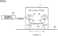
- Fig. 2 schematically illustrates a microwave photon control device 1 according to the first embodiment.
- the microwave photon control device 1 includes a first qubit 20, a second qubit 22, a first resonator 30, a second resonator 32, and a direct coupling 40 between the first resonator 30 and the second resonator 32.
- the first qubit 20 is connected to a waveguide 90 via the first resonator 30.
- the second qubit 22 is connected to the waveguide 90 via the second resonator 32.
- the first qubit 20 and the second qubit 22 are connected in parallel to the waveguide 90 via the first resonator 30 and the second resonator 32, respectively.
- a coupling between the first qubit 20 and the first resonator 30 is variable.
- a coupling between the second qubit 22 and the second resonator 32 is variable.
- a coupling between each qubit and a resonator variable by making a coupling between each qubit and a resonator variable, a relaxation rate of each qubit with respect to the waveguide 90 can be controlled.
- An interval D between the first resonator 30 and the second resonator 32 is (1/4 + n/2) times as long as a wavelength ⁇ of microwave photons.
- a specific upper limit is not provided on the value of n. Nevertheless, the value of n is preferably as small as possible because the influence of delay is exerted if the value of n becomes too large.
- the direct coupling 40 is formed between the first resonator 30 and the second resonator 32.
- the first qubit 20 and the second qubit 22 are superconducting qubits formed by superposition of a two-level system of a ground state
- a state caused when the first qubit is in the excited state and the second qubit is in the ground state is denoted by
- a state caused when the first qubit is in the ground state and the second qubit is in the excited state is denoted by
- a state caused when both the first qubit and the second qubit are in the ground state is denoted by
- a state caused when both the first qubit and the second qubit are in the excited state is denoted by
- a quantum entangled state is formed between the first qubit 20 and the second qubit 22.
- ⁇ > is represented as follows:
- ⁇ ⁇ 1 / ⁇ 2
- ⁇ denotes a phase difference of the quantum entangled state between the first qubit 20 and the second qubit 22.
- the quantum entangled state is realized by combining the execution of a C-NOT gate (e.g., refer to Non Patent Literature 3) operation performed by emitting microwaves to the first qubit 20 and the second qubit 22 from an external microwave transmitter 80, for example, and the execution of a single qubit gate operation performed by emitting microwaves resonant with each qubit.
- a C-NOT gate e.g., refer to Non Patent Literature 3
- the quantum entangled state can also be formed by causing energy exchange by bringing either one of the first qubit 20 and the second qubit 22 into the excited state, and resonating the both qubits.
- a phase difference of the quantum entangled state can be controlled by emitting nonresonant microwaves and modulating a resonant frequency of either one of the qubits, for example.
- the first qubit 20 and the second qubit 22 are connected in parallel to the waveguide 90 via the first resonator 30 and the second resonator 32, respectively.
- a coupling via the waveguide 90 between the first qubit 20 and the second qubit 22 becomes a coupling via the waveguide 90 between the first resonator 30 and the second resonator 32.
- a relaxation rate of the first resonator 30 and the second resonator 32 with respect to the waveguide 90 is denoted by ⁇
- a relaxation rate of the first resonator 30 and the second resonator 32 with respect to the waveguide 90 can be made temporally constant. Accordingly, by forming the direct coupling 40 between the first resonator 30 and the second resonator 32 using a capacitive coupling, for example, and setting the direct coupling 40 as -J (i.e., a coupling having the same size as the coupling J via the waveguide 90 between the first resonator 30 and the second resonator 32, and having an opposite sign), the coupling J via the waveguide 90 between the first resonator 30 and the second resonator 32 can be cancelled out.
- the direct coupling 40 (-J) can also be made temporally constant because the relaxation rate ⁇ of the first resonator 30 and the second resonator 32 with respect to the waveguide 90 is temporally constant.
- the microwave photon control device 1 operates while switching between a first operation mode, a second operation mode, and a third operation mode.
- a control method of the relaxation rate of qubits there is a method of controlling the strength of a coupling between a qubit and a resonator in accordance with the intensity of microwaves emitted from the external microwave transmitter 80, and controlling an effective relaxation rate of the qubit with respect to a waveguide via the resonator (e.g., refer to Non Patent Literature 1).
- a control method of the relaxation rate of qubits there is a method of controlling the strength of a coupling between a qubit and a resonator in accordance with the intensity of microwaves emitted from the external microwave transmitter 80, and controlling an effective relaxation rate of the qubit with respect to a waveguide via the resonator (e.g., refer to Non Patent Literature 1).
- this point will be described.
- Figs. 3 and 4 each illustrate an operation of the microwave photon control device 1 in the first operation mode.
- the microwave photon control device 1 emits microwave photons in one direction of the waveguide 90.
- Fig. 3 illustrates an operation of the microwave photon control device 1 that is performed when the phase difference ⁇ of the quantum entangled state between the first qubit 20 and the second qubit 22 is + ⁇ /2.
- the phase difference ⁇ of the quantum entangled state By setting the phase difference ⁇ of the quantum entangled state to + ⁇ /2 or - ⁇ /2, photons can be emitted in opposite directions in accordance with the phase difference ⁇ .
- photons emitted from the microwave photon control device 1 propagate only rightward through the waveguide 90. In other words, photons emitted from the microwave photon control device 1 neither propagate leftward through the waveguide 90, nor be reabsorbed by the first qubit 20 and the second qubit 22.
- Fig. 4 illustrates an operation of the microwave photon control device 1 that is performed when the phase difference ⁇ between the first qubit 20 and the second qubit 22 is - ⁇ /2.
- photons emitted from the microwave photon control device 1 propagate only leftward through the waveguide 90 in contrast to Fig. 3 .
- photons emitted from the microwave photon control device 1 neither propagate rightward through the waveguide 90, nor be reabsorbed by the first qubit 20 and the second qubit 22.
- the microwave photon control device 1 emits microwave photons only in one direction of the waveguide 90 in the first operation mode because an interval between the first qubit 20 and the second qubit 22 is (1/4 + n/2) times as long as the wavelength of microwave photons.
- an interval between the first qubit 20 and the second qubit 22 is (1/4 + n/2) times as long as the wavelength of microwave photons.
- Figs. 5 and 6 each illustrate an operation of the microwave photon control device 1 in the second operation mode.
- the microwave photon control device 1 absorbs microwave photons that have propagated from one direction of the waveguide 90.
- g,g> caused when both the first qubit 20 and the second qubit 22 are in the ground state is prepared as an initial state.
- photons that have entered the microwave photon control device 1 are absorbed by qubits. The qubits consequently enter the excited state.
- the microwave photon control device 1 absorbs all the photons that have propagated leftward through the waveguide 90. In other words, photons that have entered the microwave photon control device 1 neither pass through the microwave photon control device 1 to propagate leftward through the waveguide 90, nor be reflected by the microwave photon control device 1 to propagate rightward through the waveguide 90. If photons are absorbed, the phase difference ⁇ of the quantum entangled state between the first qubit 20 and the second qubit 22 consequently becomes + ⁇ /2.
- the microwave photon control device 1 absorbs all the photons that have propagated rightward through the waveguide 90. In other words, photons that have entered the microwave photon control device 1 neither pass through the microwave photon control device 1 to propagate rightward through the waveguide 90, nor be reflected by the microwave photon control device 1 to propagate leftward through the waveguide 90. If photons are absorbed, the phase difference ⁇ of the quantum entangled state between the first qubit 20 and the second qubit 22 consequently becomes - ⁇ /2.
- the microwave photon control device 1 absorbs all the photons that have propagated in one direction of the waveguide 90 in the second operation mode because an interval between the first qubit 20 and the second qubit 22 is (1/4 + n/2) times as long as the wavelength of microwave photons. With this configuration, along with the absorption of photons, photons emitted from the first qubit 20 and the second qubit 22 disappear due to interference, and photons that have propagated from the waveguide 90 in one direction are fully absorbed.
- Figs. 7 and 8 each illustrate an operation of the microwave photon control device 1 in the third operation mode.
- the microwave photon control device 1 lets through microwave photons that have propagated from one direction of the waveguide 90, to propagate.
- a coupling between the first qubit 20 and second resonator 30, and a coupling between the second qubit 22 and the second resonator 32 are both turned off as an initial state. With this configuration, photons fully pass through the microwave photon control device 1 to propagate without being reflected or absorbed by the microwave photon control device 1.
- the microwave photon control device 1 lets through all the photons that have propagated leftward through the waveguide 90. In other words, photons that have entered the microwave photon control device 1 neither be absorbed by the first qubit 20 and the second qubit 22, nor be reflected by the microwave photon control device 1 to propagate rightward through the waveguide 90.
- the microwave photon control device 1 lets through all the photons that have propagated rightward through the waveguide 90. In other words, photons that have entered the microwave photon control device 1 neither be absorbed by the first qubit 20 and the second qubit 22, nor be reflected by the microwave photon control device 1 to propagate leftward through the waveguide 90.
- the microwave photon control device 1 lets through all the photons that have propagated in one direction through the waveguide 90, to propagate in the third operation mode because an interval between the first resonator 30 and the second resonator 32 is (1/4 + n/2) times as long as the wavelength of microwave photons.
- an interval between the first resonator 30 and the second resonator 32 is (1/4 + n/2) times as long as the wavelength of microwave photons.
- the propagation direction of propagation microwave photons in a quantum network can be controlled without using a circulator.
- the direct coupling 40 can be made temporally constant, the direct coupling 40 can be easily realized without requiring particular temporal control.
- the microwave photon control device 1 can be used while switching between the first, second, and third operation modes, the microwave photon control device 1 is preferable as a router.
- Fig. 9 schematically illustrates a microwave photon control device 2 according to the second embodiment.
- the microwave photon control device 2 includes a first qubit 20, a second qubit 22, and a direct coupling 42 between the first qubit 20 and the second qubit 22.
- the first qubit 20 and the second qubit 22 are directly connected in parallel to a waveguide 90.
- an interval D between the first qubit 20 and the second qubit 22 is (1/4 + n/2) times as long as a wavelength ⁇ of microwave photons.
- the direct coupling 42 is directly formed between the first qubit 20 and the second qubit 22.
- Other configurations and operations of the microwave photon control device 2 are similar to those of the microwave photon control device 1.
- the first qubit 20 and the second qubit 22 are directly connected to the waveguide 90 not via resonators.
- a relaxation rate ⁇ of the first qubit 20 and the second qubit 22 with respect to the waveguide 90 temporally changes.
- control of the relaxation rate can be executed by using inductance modulation of SQUID (a superconducting quantum interference device), for example (e.g., refer to Non Patent Literature 4).
- SQUID superconducting quantum interference device
- a coupling via the waveguide 90 is generated between the first qubit 20 and the second qubit 22. Because the interval D between the both qubits is (1/4 + n/2)* ⁇ , at the coupling via the waveguide, energy exchange between both qubits becomes dominant, and the quantum entangled state between both qubits is thereby destroyed. It is therefore demanded to cancel out a coupling via a waveguide between both qubits.
- the direct coupling 42 between the first qubit 20 and the second qubit 22 can be formed by forming the direct coupling 42 between the first qubit 20 and the second qubit 22, and temporally changing the direct coupling 42 to become -J(t) (i.e., a coupling having the same size as the coupling J via the waveguide 90 between the first resonator 30 and the second resonator 32, and having an opposite sign), the coupling J via the waveguide 90 between the first qubit 20 and the second qubit 22 can be cancelled out.
- -J(t) i.e., a coupling having the same size as the coupling J via the waveguide 90 between the first resonator 30 and the second resonator 32, and having an opposite sign
- inductance modulation of the SQUID can be used (e.g., refer to Non Patent Literature 5).
- the direct coupling 42 can also be temporally controlled.
- the direct coupling 42 may be formed using a capacitive coupling, and the direct coupling 42 may be directly temporally controlled.
- the propagation direction of propagation microwave photons in a quantum network can be controlled without using a circulator as well.
- the number of components can be reduced because resonators are not required while it is necessary to temporally control the direct coupling 42.
- the microwave photon control devices may further include a coupling controller and a quantum entangled state generator.
- the coupling controller controls a coupling between the first qubit and the waveguide, and a coupling between the second qubit 22 and the waveguide.
- the quantum entangled state generator generates a quantum entangled state between the first qubit and the second qubit. In this manner, by the microwave photon control device including the coupling controller and the quantum entangled state generator thereinside, a design freedom degree can be increased.
- a microwave photon transmitter includes a first qubit and a second qubit that are connected in parallel to a waveguide through which microwave photons propagate, and a direct coupling between the first qubit and the second qubit.
- An interval between the first qubit and the second qubit is (1/4 + n/2) times as long as the wavelength of microwave photons.
- a quantum entangled state is formed between the first qubit and the second qubit.
- the above-described direct coupling cancels out a coupling via the waveguide between the first qubit and the second qubit, and by a relaxation rate of the first qubit and the second qubit, and the phase of the quantum entangled state being controlled, microwave photons are emitted in one direction of the waveguide.
- the present embodiment forms a microwave photon transmitter by extracting the first operation mode from the microwave photon control device of the second embodiment.
- a microwave photon transmitter that emits microwave photons only in one direction of a waveguide can be provided.
- the microwave photon transmitter may further include a first resonator and a second resonator.
- the first qubit and the second qubit are connected to the waveguide via the first resonator and the second resonator, respectively.
- the direct coupling is formed between the first resonator and the second resonator.
- the direct coupling is temporally constant.
- the control of couplings between the first qubit and the second qubit, and the waveguide is control of a coupling between the first qubit and the first resonator, and a coupling between the second qubit and the second resonator.
- a microwave photon receiver includes a first qubit and a second qubit that are connected in parallel to a waveguide through which microwave photons propagate, and a direct coupling between the first qubit and the second qubit.
- An interval between the first qubit and the second qubit is (1/4 + n/2) times as long as the wavelength of microwave photons.
- a quantum entangled state is formed between the first qubit and the second qubit. The above-described direct coupling cancels out a coupling via the waveguide between the first qubit and the second qubit, and by a relaxation rate of the first qubit and the second qubit, and the phase of the quantum entangled state being controlled, microwave photons that have propagated from one direction of the waveguide are absorbed.
- the present embodiment forms a microwave photon receiver by extracting the second operation mode from the microwave photon control device of the second embodiment.
- a microwave photon receiver that absorbs all photons that have propagated in one direction through a waveguide can be provided.
- the microwave photon receiver may further include a first resonator and a second resonator. At this time, the first qubit and the second qubit are connected to the waveguide via the first resonator and the second resonator, respectively.
- the direct coupling is formed between the first resonator and the second resonator. The direct coupling is temporally constant.
- a microwave photon repeater includes a first qubit and a second qubit that are connected in parallel to a waveguide through which microwave photons propagate, and a direct coupling between the first qubit and the second qubit.
- An interval between the first qubit and the second qubit is (1/4 + n/2) times as long as the wavelength of microwave photons.
- a quantum entangled state is formed between the first qubit and the second qubit. The above-described direct coupling cancels out a coupling via the waveguide between the first qubit and the second qubit, and by a relaxation rate of the first qubit and the second qubit, and the phase of the quantum entangled state being controlled, photons that have propagated in one direction through the waveguide are all passed through to propagate.
- the present embodiment forms a microwave photon repeater by extracting the third operation mode from the microwave photon control device of the second embodiment.
- photons that have propagated in one direction through the waveguide can be relayed without destroying the quantum entangled state of the photons.
- the microwave photon repeater may further include a first resonator and a second resonator. At this time, the first qubit and the second qubit are connected to the waveguide via the first resonator and the second resonator, respectively.
- the direct coupling is formed between the first resonator and the second resonator. The direct coupling is temporally constant.
- the control of a relaxation rate of the first qubit and the second qubit, and a phase of the quantum entangled state is performed using microwaves transmitted from the external microwave transmitter.
- the control of the relaxation rate is performed using inductance modulation of the SQUID. Nevertheless, the control is not limited to these types of control, and these types of control may be performed using any preferred method.
- qubits are superconducting qubits. Nevertheless, qubits are not limited to these, and qubits may be any preferred qubits such as cooled ion qubits, for example.
- the propagation microwave photon is not limited to this, and the propagation microwave photon may be a superposition state of a vacuum state and a single microwave photon state, or a superposition state of a time multimode of a single microwave photon.
- a difference in photoemission between a case where a direct coupling exists between resonators, and a case where a direct coupling does not exist, in a case where a microwave photon control device operates in the first operation mode is checked by simulation.
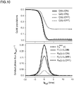
- Fig. 10 illustrates a simulation result indicating a difference in photoemission that is attributed to the existence or non-existence of the direct coupling 40 between resonators when the microwave photon control device 1 in Fig. 2 operates in the first operation mode.
- the microwave photon control device 1 is adjusted in phase in such a manner as to emit photons rightward through the waveguide 90.
- FIG. 10 An upper part of Fig. 10 illustrates time changes of qubit populations of the first qubit 20 and the second qubit 22.
- a lower part of Fig. 10 illustrates time changes of fluxes of photons emitted from the first qubit 20 and the second qubit 22.
- the time change of the qubit 20 is indicated by Q1
- the time change of the qubit 22 is indicated by Q2.
- a time change caused in a case where the direct coupling 40 exists is indicated by a solid line
- a time change caused in a case where the direct coupling 40 does not exist is indicated by a dotted line. More specifically, in the upper part,
- the maximum value of the PRideal(t) is PRideal(0) ⁇ 0.25.
- the maximum values of the fluxes PR(t)(c.OFF) and PL(t)(c.OFF) are PR(0) (c.OFF) ⁇ 0.16 and PL(0)(c.OFF) ⁇ 0.04, respectively.
- Fig. 11 schematically illustrates a quantum computer 3 according to the sixth embodiment.
- the quantum computer 3 includes a plurality of microwave photon control devices 11 described above that are arranged at ends of a quantum circuit module 60 on which a plurality of superconducting qubits 50 are implemented, and transmit and receive quantum states between the quantum circuit modules 60.
- the writing of the quantum state into superconducting qubits and readout of the quantum state from superconducting qubits are performed by emitting microwaves to superconducting qubits.
- about two to four cables are required for each qubit.
- the quantum computer 3 is operated under extremely-low temperature, a circuit on which superconducting qubits are implemented needs to be stored into a freezing machine. Accordingly, it is physically difficult to implement a large number of qubits onto one substrate. In other words, it is not easy to realize a large-scale quantum computer using one substrate.
- quantum circuit modules are connected in a quantum manner by implementing a plurality of microwave control devices (pairs of superconducting qubits) described above, at the ends of quantum circuit modules. With this configuration, it becomes possible to easily transmit a quantum state generated in a quantum circuit module, to another quantum circuit module as a microwave photon, and receive a quantum state in turn. In this manner, according to the present embodiment, a quantum computer can be effectively formed.
- the present invention can be used in a microwave photon control device, a microwave photon transmitter, a microwave photon receiver, and a microwave photon repeater.
- microwave photon control device 1 microwave photon control device, 2 microwave photon control device, 3 quantum computer, 11 microwave photon control device, 20 first qubit, 22 second qubit, 30 first resonator, 32 second resonator, 40 direct coupling, 50 superconducting qubit, 60 quantum circuit module, 80 microwave transmitter, 90 waveguide
Landscapes
- Physics & Mathematics (AREA)
- Engineering & Computer Science (AREA)
- Theoretical Computer Science (AREA)
- General Physics & Mathematics (AREA)
- General Engineering & Computer Science (AREA)
- Data Mining & Analysis (AREA)
- Computing Systems (AREA)
- Computer Networks & Wireless Communication (AREA)
- Signal Processing (AREA)
- Artificial Intelligence (AREA)
- Computational Mathematics (AREA)
- Condensed Matter Physics & Semiconductors (AREA)
- Optics & Photonics (AREA)
- Evolutionary Computation (AREA)
- Software Systems (AREA)
- Mathematical Analysis (AREA)
- Mathematical Optimization (AREA)
- Pure & Applied Mathematics (AREA)
- Electromagnetism (AREA)
- Mathematical Physics (AREA)
- High Energy & Nuclear Physics (AREA)
- Spectroscopy & Molecular Physics (AREA)
- Superconductor Devices And Manufacturing Methods Thereof (AREA)
- Optical Integrated Circuits (AREA)
- Optical Communication System (AREA)
Applications Claiming Priority (2)
| Application Number | Priority Date | Filing Date | Title |
|---|---|---|---|
| JP2020001696 | 2020-01-08 | ||
| PCT/JP2020/049180 WO2021140995A1 (ja) | 2020-01-08 | 2020-12-28 | マイクロ波光子制御装置、マイクロ波光子送信器、マイクロ波光子受信器、マイクロ波光子中継器および量子コンピュータ |
Publications (2)
| Publication Number | Publication Date |
|---|---|
| EP4089751A1 true EP4089751A1 (de) | 2022-11-16 |
| EP4089751A4 EP4089751A4 (de) | 2024-02-07 |
Family
ID=76787971
Family Applications (1)
| Application Number | Title | Priority Date | Filing Date |
|---|---|---|---|
| EP20912052.6A Pending EP4089751A4 (de) | 2020-01-08 | 2020-12-28 | Mikrowellen-photonen-steuervorrichtung, mikrowellen-photonensender, mikrowellen-photonen-empfänger, mikrowellen-photonen-repeater und quantenrechner |
Country Status (5)
| Country | Link |
|---|---|
| US (1) | US12184339B2 (de) |
| EP (1) | EP4089751A4 (de) |
| JP (1) | JP7586504B2 (de) |
| CN (1) | CN114930739B (de) |
| WO (1) | WO2021140995A1 (de) |
Cited By (1)
| Publication number | Priority date | Publication date | Assignee | Title |
|---|---|---|---|---|
| WO2025259144A1 (en) * | 2024-06-10 | 2025-12-18 | Telefonaktiebolaget Lm Ericsson (Publ) | Method and apparatus for use in quantum processing |
Families Citing this family (2)
| Publication number | Priority date | Publication date | Assignee | Title |
|---|---|---|---|---|
| WO2022190684A1 (ja) * | 2021-03-11 | 2022-09-15 | 国立研究開発法人科学技術振興機構 | 量子もつれ生成装置、量子もつれ生成方法および量子コンピュータ |
| CN118249063B (zh) * | 2024-05-24 | 2025-01-10 | 山东云海国创云计算装备产业创新中心有限公司 | 环形器及量子计算机 |
Family Cites Families (10)
| Publication number | Priority date | Publication date | Assignee | Title |
|---|---|---|---|---|
| CN201145801Y (zh) * | 2007-06-15 | 2008-11-05 | 浙江大学 | 实现多光子场波导模式纠缠的装置 |
| US7889992B1 (en) * | 2009-09-21 | 2011-02-15 | International Business Machines Corporation | Hybrid superconductor-optical quantum repeater |
| GB2502509B (en) * | 2012-03-30 | 2016-08-03 | Toshiba Res Europe Ltd | Photon Source |
| CN104330938B (zh) * | 2014-10-16 | 2017-02-22 | 南京大学 | 基于光学超晶格和波导光路的量子光源芯片 |
| JP6550146B2 (ja) * | 2015-03-31 | 2019-07-24 | コーニング インコーポレイテッド | 量子鍵生成のためのシステム及び方法 |
| US9843312B2 (en) * | 2015-09-30 | 2017-12-12 | International Business Machines Corporation | Multimode Josephson parametric converter: coupling Josephson ring modulator to metamaterial |
| CN108604316B (zh) * | 2015-11-27 | 2022-11-15 | 光子公司 | 用于与自旋存储的量子信息交互的系统、装置及方法 |
| US9680452B1 (en) * | 2016-10-17 | 2017-06-13 | International Business Machines Corporation | Sum frequency generator in the microwave domain for quantum communication and computation applications |
| TWI809224B (zh) * | 2018-11-22 | 2023-07-21 | 國立研究開發法人科學技術振興機構 | 非線性微波濾波器 |
| US11387913B2 (en) * | 2019-05-30 | 2022-07-12 | At&T Intellectual Property I, L.P. | System and method for provisioning of entangled-photon pairs |
-
2020
- 2020-12-28 WO PCT/JP2020/049180 patent/WO2021140995A1/ja not_active Ceased
- 2020-12-28 JP JP2021570037A patent/JP7586504B2/ja active Active
- 2020-12-28 EP EP20912052.6A patent/EP4089751A4/de active Pending
- 2020-12-28 CN CN202080090969.6A patent/CN114930739B/zh active Active
- 2020-12-28 US US17/790,819 patent/US12184339B2/en active Active
Cited By (1)
| Publication number | Priority date | Publication date | Assignee | Title |
|---|---|---|---|---|
| WO2025259144A1 (en) * | 2024-06-10 | 2025-12-18 | Telefonaktiebolaget Lm Ericsson (Publ) | Method and apparatus for use in quantum processing |
Also Published As
| Publication number | Publication date |
|---|---|
| JP7586504B2 (ja) | 2024-11-19 |
| EP4089751A4 (de) | 2024-02-07 |
| CN114930739B (zh) | 2023-11-28 |
| WO2021140995A1 (ja) | 2021-07-15 |
| US20220376797A1 (en) | 2022-11-24 |
| CN114930739A (zh) | 2022-08-19 |
| JPWO2021140995A1 (de) | 2021-07-15 |
| US12184339B2 (en) | 2024-12-31 |
Similar Documents
| Publication | Publication Date | Title |
|---|---|---|
| US12184339B2 (en) | Microwave photon control device, microwave photon transmitter, microwave photon receiver, microwave photon repeater, and quantum computer | |
| CN109685216B (zh) | 一种量子计算机 | |
| EP3724828B1 (de) | Kompakter mehrpoliger quantenbit-messfilter | |
| Neumeier et al. | Single-photon transistor in circuit quantum electrodynamics | |
| CN102498496B (zh) | 混合超导体-光量子中继器 | |
| Zhang et al. | Charge-noise insensitive chiral photonic interface for waveguide circuit QED | |
| Metelmann et al. | Nonreciprocal signal routing in an active quantum network | |
| US11983607B2 (en) | Whispering-gallery mode optical resonator | |
| CN108475353A (zh) | 采用固定频率超导量子比特的多量子比特可调耦合结构 | |
| US10621503B1 (en) | Quantum computer hardware with reflectionless filters for thermalizing radio frequency signals | |
| US12555020B2 (en) | Entangling photonic graphs | |
| US11972324B2 (en) | Entangling gate for entangled graph state generation | |
| WO2020169224A1 (en) | Quantum computing device using two gate types to prevent frequency collisions in superconducting quantum computers | |
| Shi et al. | Multiplexed control scheme for scalable quantum information processing with superconducting qubits | |
| CN110443708A (zh) | 平行链交易方法、设备和存储介质 | |
| Zhang et al. | Robust beam splitter with fast quantum state transfer through a topological interface | |
| Barzanjeh et al. | Nonreciprocity in quantum technology | |
| KR101880367B1 (ko) | 광 주입 잠금 반도체 레이저의 직접 변조를 이용한 복소 형식 광 신호 발생 방법 및 장치 | |
| CN114696906B (zh) | 光电振荡伊辛机及组合优化问题的解决方法 | |
| KR20200075508A (ko) | 2차원 배열형 대전력 초고주파 송신 시스템 | |
| Wang et al. | Heralded long-distance entanglement schemes for waveguide systems in quantum networks | |
| US20260127478A1 (en) | Entangling gate (as amended) | |
| US12248851B1 (en) | Thermalization and attenuation of signals within quantum computing systems via directional couplers | |
| Hummelt et al. | Design of a volume mode W-band TWT amplifier | |
| Castorina | LABORATORI NAZIONALI DI FRASCATI |
Legal Events
| Date | Code | Title | Description |
|---|---|---|---|
| STAA | Information on the status of an ep patent application or granted ep patent |
Free format text: STATUS: THE INTERNATIONAL PUBLICATION HAS BEEN MADE |
|
| PUAI | Public reference made under article 153(3) epc to a published international application that has entered the european phase |
Free format text: ORIGINAL CODE: 0009012 |
|
| STAA | Information on the status of an ep patent application or granted ep patent |
Free format text: STATUS: REQUEST FOR EXAMINATION WAS MADE |
|
| 17P | Request for examination filed |
Effective date: 20220706 |
|
| AK | Designated contracting states |
Kind code of ref document: A1 Designated state(s): AL AT BE BG CH CY CZ DE DK EE ES FI FR GB GR HR HU IE IS IT LI LT LU LV MC MK MT NL NO PL PT RO RS SE SI SK SM TR |
|
| DAV | Request for validation of the european patent (deleted) | ||
| DAX | Request for extension of the european patent (deleted) | ||
| REG | Reference to a national code |
Ref country code: DE Ref legal event code: R079 Free format text: PREVIOUS MAIN CLASS: H01L0039220000 Ipc: G06N0010000000 |
|
| A4 | Supplementary search report drawn up and despatched |
Effective date: 20240108 |
|
| RIC1 | Information provided on ipc code assigned before grant |
Ipc: G06N 10/40 20220101ALI20240102BHEP Ipc: H04B 10/70 20130101ALI20240102BHEP Ipc: H04B 10/27 20130101ALI20240102BHEP Ipc: G06N 10/00 20220101AFI20240102BHEP |