EP4089702A1 - Controller and key structure - Google Patents
Controller and key structure Download PDFInfo
- Publication number
- EP4089702A1 EP4089702A1 EP21194308.9A EP21194308A EP4089702A1 EP 4089702 A1 EP4089702 A1 EP 4089702A1 EP 21194308 A EP21194308 A EP 21194308A EP 4089702 A1 EP4089702 A1 EP 4089702A1
- Authority
- EP
- European Patent Office
- Prior art keywords
- contact
- rib
- key
- pressed
- substrate
- Prior art date
- Legal status (The legal status is an assumption and is not a legal conclusion. Google has not performed a legal analysis and makes no representation as to the accuracy of the status listed.)
- Granted
Links
Images





Classifications
-
- H—ELECTRICITY
- H01—ELECTRIC ELEMENTS
- H01H—ELECTRIC SWITCHES; RELAYS; SELECTORS; EMERGENCY PROTECTIVE DEVICES
- H01H13/00—Switches having rectilinearly-movable operating part or parts adapted for pushing or pulling in one direction only, e.g. push-button switch
- H01H13/70—Switches having rectilinearly-movable operating part or parts adapted for pushing or pulling in one direction only, e.g. push-button switch having a plurality of operating members associated with different sets of contacts, e.g. keyboard
- H01H13/702—Switches having rectilinearly-movable operating part or parts adapted for pushing or pulling in one direction only, e.g. push-button switch having a plurality of operating members associated with different sets of contacts, e.g. keyboard with contacts carried by or formed from layers in a multilayer structure, e.g. membrane switches
- H01H13/705—Switches having rectilinearly-movable operating part or parts adapted for pushing or pulling in one direction only, e.g. push-button switch having a plurality of operating members associated with different sets of contacts, e.g. keyboard with contacts carried by or formed from layers in a multilayer structure, e.g. membrane switches characterised by construction, mounting or arrangement of operating parts, e.g. push-buttons or keys
-
- A—HUMAN NECESSITIES
- A63—SPORTS; GAMES; AMUSEMENTS
- A63F—CARD, BOARD, OR ROULETTE GAMES; INDOOR GAMES USING SMALL MOVING PLAYING BODIES; VIDEO GAMES; GAMES NOT OTHERWISE PROVIDED FOR
- A63F13/00—Video games, i.e. games using an electronically generated display having two or more dimensions
- A63F13/20—Input arrangements for video game devices
- A63F13/24—Constructional details thereof, e.g. game controllers with detachable joystick handles
-
- A—HUMAN NECESSITIES
- A63—SPORTS; GAMES; AMUSEMENTS
- A63F—CARD, BOARD, OR ROULETTE GAMES; INDOOR GAMES USING SMALL MOVING PLAYING BODIES; VIDEO GAMES; GAMES NOT OTHERWISE PROVIDED FOR
- A63F13/00—Video games, i.e. games using an electronically generated display having two or more dimensions
- A63F13/20—Input arrangements for video game devices
- A63F13/21—Input arrangements for video game devices characterised by their sensors, purposes or types
- A63F13/214—Input arrangements for video game devices characterised by their sensors, purposes or types for locating contacts on a surface, e.g. floor mats or touch pads
-
- G—PHYSICS
- G06—COMPUTING OR CALCULATING; COUNTING
- G06F—ELECTRIC DIGITAL DATA PROCESSING
- G06F3/00—Input arrangements for transferring data to be processed into a form capable of being handled by the computer; Output arrangements for transferring data from processing unit to output unit, e.g. interface arrangements
- G06F3/01—Input arrangements or combined input and output arrangements for interaction between user and computer
- G06F3/03—Arrangements for converting the position or the displacement of a member into a coded form
- G06F3/033—Pointing devices displaced or positioned by the user, e.g. mice, trackballs, pens or joysticks; Accessories therefor
-
- H—ELECTRICITY
- H01—ELECTRIC ELEMENTS
- H01H—ELECTRIC SWITCHES; RELAYS; SELECTORS; EMERGENCY PROTECTIVE DEVICES
- H01H2215/00—Tactile feedback
- H01H2215/004—Collapsible dome or bubble
- H01H2215/022—Asymmetric; Elliptic; Square
-
- H—ELECTRICITY
- H01—ELECTRIC ELEMENTS
- H01H—ELECTRIC SWITCHES; RELAYS; SELECTORS; EMERGENCY PROTECTIVE DEVICES
- H01H2221/00—Actuators
- H01H2221/008—Actuators other then push button
- H01H2221/012—Joy stick type
-
- H—ELECTRICITY
- H01—ELECTRIC ELEMENTS
- H01H—ELECTRIC SWITCHES; RELAYS; SELECTORS; EMERGENCY PROTECTIVE DEVICES
- H01H2221/00—Actuators
- H01H2221/074—One molded piece
-
- H—ELECTRICITY
- H01—ELECTRIC ELEMENTS
- H01H—ELECTRIC SWITCHES; RELAYS; SELECTORS; EMERGENCY PROTECTIVE DEVICES
- H01H2221/00—Actuators
- H01H2221/078—Different operating parts on a bigger one
-
- H—ELECTRICITY
- H01—ELECTRIC ELEMENTS
- H01H—ELECTRIC SWITCHES; RELAYS; SELECTORS; EMERGENCY PROTECTIVE DEVICES
- H01H2227/00—Dimensions; Characteristics
- H01H2227/022—Collapsable dome
-
- H—ELECTRICITY
- H01—ELECTRIC ELEMENTS
- H01H—ELECTRIC SWITCHES; RELAYS; SELECTORS; EMERGENCY PROTECTIVE DEVICES
- H01H2235/00—Springs
- H01H2235/008—Rubber spring
-
- H—ELECTRICITY
- H01—ELECTRIC ELEMENTS
- H01H—ELECTRIC SWITCHES; RELAYS; SELECTORS; EMERGENCY PROTECTIVE DEVICES
- H01H25/00—Switches with compound movement of handle or other operating part
- H01H25/04—Operating part movable angularly in more than one plane, e.g. joystick
- H01H25/041—Operating part movable angularly in more than one plane, e.g. joystick having a generally flat operating member depressible at different locations to operate different controls
Definitions
- the present disclosure relates to a controller and a key structure.
- Patent Literature 1 discloses a controller including a key switch.
- a controller includes a key top, a substrate, and an elastic member.
- the elastic member is provided between the key top and the substrate.
- the elastic member includes a pressed portion pressed as the key top swings, a base in contact with the substrate, a skirt portion that connects the pressed portion and the base to each other and is elastically deformed as the pressed portion is pressed, and a pressing member provided in a prescribed region that is a part of the pressed portion, is opposed to the substrate, and is surrounded by the skirt portion, at least a top surface of the pressing member opposed to the substrate being conductive.
- the top surface is constructed to press a contact as the skirt portion is elastically deformed.
- the substrate includes the contact at a position pressed by the top surface.
- a direction in which the key top and the elastic member are layered is defined as a first direction.
- a direction perpendicular to the first direction is defined as a second direction.
- the pressing member is surrounded by an outer peripheral edge of the prescribed region.
- a distance between an end of the outer peripheral edge of the prescribed region on a side of a swing center of the key top and an end of the top surface on the side of the swing center is longer than a distance between an end of the outer peripheral edge of the prescribed region opposite to the swing center and an end of the top surface opposite to the swing center.
- the contact is located closer to the swing center than the top surface.
- the key top In operating the key top, the key top may rotate inward.
- the pressing member When the key top rotates inward, the pressing member is also lowered while being rotated inward. Therefore, the pressing member is inclined with respect to the surface of the contact. Consequently, an area of contact between the pressing member and the contact becomes smaller. In this case, contact sensitivity between the pressing member and the contact may become lower.
- the distance between the end of the outer peripheral edge (a first inner end) of the prescribed region on the side of the swing center of the key top and the end (a second inner end) of the top surface on the side of the swing center is longer than the distance between the end of the outer peripheral edge (a first outer end) of the prescribed region opposite to the swing center and the end (a second outer end) of the top surface opposite to the swing center.
- the pressing member is provided on an outer side in the prescribed region of the pressed portion. Therefore, a radius of rotation of the pressing member can be larger than when the pressing member is provided on an inner side in the prescribed region of the pressed portion. Consequently, the pressing member can more linearly be lowered. Therefore, the area of contact between the pressing member and the contact can be made larger. Therefore, lowering in contact sensitivity between the pressing member and the contact can be suppressed.
- the controller according to the present disclosure can more effectively secure a large area of contact between the pressing member and the contact when the key top is reduced in size.
- a central position of the pressing member may be displaced from a central position of the contact. In this case, contact sensitivity between the pressing member and the contact may be lowered.
- the contact in the second direction, the contact is located closer to the swing center than the pressing member. Therefore, when the pressing member is shifted inward, the central position of the pressing member moves in a direction toward the central position of the contact. Therefore, displacement of the central position of the pressing member from the central position of the contact can be suppressed. Consequently, lowering in contact sensitivity between the pressing member and the contact can further be suppressed.
- the key top may include a rib that surrounds at least a part of an outer circumferential side surface of the pressed portion.
- the rib may include an outer rib portion and an inner rib portion provided closer to the swing center than the outer rib portion.
- the inner rib portion may be larger in height than the outer rib portion.
- the outer rib portion is larger in radius of rotation than the inner rib portion. Therefore, when the outer rib portion is equal in height to the inner rib portion, the outer rib portion is located below the inner rib portion at the time of pressing of the key top. Therefore, the outer rib portion may interfere with the skirt portion more than the inner rib portion.
- the height of the inner rib portion By setting the height of the inner rib portion to be larger than the height of the outer rib portion, interference of the outer rib portion with the skirt portion can be suppressed while the inner rib portion securely holds the pressed portion.
- the rib in the direction in parallel to the first direction, the rib may increase in height from the outer rib portion toward the inner rib portion.
- the rib can more securely be attached to the pressed portion while interference of the rib with the skirt portion is suppressed.
- each of the inner rib portion and the outer rib portion may be constructed such that, when the key top is pressed down, a distance between the substrate and the inner rib portion is equal to a distance between the substrate and the outer rib portion.
- a direction being in parallel to the second direction and extending radially from the swing center is defined as a radial direction.
- a clearance between the outer circumferential side surface and the rib in a third direction that passes through a center of the rib and is perpendicular to the radial direction may be smaller than a clearance between the outer circumferential side surface and the rib in the radial direction that passes through the center of the rib.
- the rib may include an inner circumferential surface and a protrusion that protrudes from the inner circumferential surface in the third direction.
- the key top when viewed in the first direction, may be in a cross shape.
- a key structure includes a key top and an elastic member.
- the elastic member is opposed to the key top.
- the elastic member includes a pressed portion pressed as the key top swings, a base distant from the pressed portion, a skirt portion that connects the pressed portion and the base to each other and is elastically deformed as the pressed portion is pressed, and a pressing member provided in a prescribed region that is a part of the pressed portion and is surrounded by the skirt portion, at least a top surface of the pressing member being conductive.
- a direction in which the key top and the elastic member are layered is defined as a first direction.
- a direction perpendicular to the first direction is defined as a second direction.
- the pressing member When viewed in the first direction, the pressing member is surrounded by an outer peripheral edge of the prescribed region.
- a distance between an end of the outer peripheral edge of the prescribed region on a side of a swing center of the key top and an end of the top surface on the side of the swing center is longer than a distance between an end of the outer peripheral edge of the prescribed region opposite to the swing center and an end of the top surface opposite to the swing center.
- the distance between the end of the outer peripheral edge (a first inner end) of the prescribed region on the side of the swing center of the key top and the end (a second inner end) of the top surface on the side of the swing center is longer than the distance between the end of the outer peripheral edge (a first outer end) of the prescribed region opposite to the swing center and the end (a second outer end) of the top surface opposite to the swing center.
- the pressing member is provided on the outer side in the prescribed region of the pressed portion. Therefore, a radius of rotation of the pressing member can be larger than when the pressing member is provided on the inner side in the prescribed region of the pressed portion. Consequently, the pressing member can more linearly be lowered. Consequently, the area of contact between the pressing member and the contact can be made larger. Therefore, lowering in contact sensitivity between the pressing member and the contact can be suppressed.
- the key top may include a rib that surrounds at least a part of an outer circumferential side surface of the pressed portion.
- the rib may include an outer rib portion and an inner rib portion provided closer to the swing center than the outer rib portion.
- the inner rib portion may be larger in height than the outer rib portion.
- the outer rib portion is larger in radius of rotation than the inner rib portion. Therefore, when the outer rib portion is equal in height to the inner rib portion, the outer rib portion is located below the inner rib portion at the time of pressing of the key top. Therefore, the outer rib portion may interfere with the skirt portion more than the inner rib portion.
- the height of the inner rib portion By setting the height of the inner rib portion to be larger than the height of the outer rib portion, interference of the outer rib portion with the skirt portion can be suppressed while the inner rib portion securely holds the pressed portion.
- the rib in the direction in parallel to the first direction, the rib may increase in height from the outer rib portion toward the inner rib portion.
- the rib can more securely be attached to the pressed portion while interference of the rib with the skirt portion is suppressed.
- a direction being in parallel to the second direction and extending radially from the swing center is defined as a radial direction.
- a clearance between the outer circumferential side surface and the rib in a third direction that passes through a center of the rib and is perpendicular to the radial direction may be smaller than a clearance between the outer circumferential side surface and the rib in the radial direction that passes through the center of the rib.
- the rib may include an inner circumferential surface and a protrusion that protrudes from the inner circumferential surface in the third direction.
- the key top when viewed in the first direction, the key top may be in a cross shape.
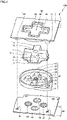
- Fig. 1 is an exploded schematic perspective view illustrating a construction of controller 100 according to the first embodiment.
- controller 100 mainly includes a housing 40, a key top 10, an elastic member 20, and a substrate 30.
- Housing 40 includes a seventh surface 7, an eighth surface 8, a first inner wall surface 43, a first fixing portion 41, a second fixing portion 42, and a first annular member 48.
- Eighth surface 8 is located opposite to seventh surface 7.
- Housing 40 is provided with a first through hole 49.
- First through hole 49 is defined by first inner wall surface 43.
- First through hole 49 opens in each of seventh surface 7 and eighth surface 8.
- Eighth surface 8 is opposed to substrate 30.
- Eighth surface 8 is provided with first fixing portion 41, second fixing portion 42, and first annular member 48.
- Key top 10 includes a fifth surface 5, a sixth surface 6, a key member 11, and a projecting portion 12.
- Sixth surface 6 is located opposite to fifth surface 5.
- a recess may be provided in a central portion 13 of fifth surface 5.
- Key member 11 may extend in four directions from central portion 13. For example, four key members 11 are provided.
- Key member 11 defines fifth surface 5.
- Projecting portion 12 is contiguous to key member 11. Projecting portion 12 may extend outward from key member 11. Projecting portion 12 defines sixth surface 6.
- Key top 10 is made, for example, of a resin.
- Elastic member 20 includes a first surface 1, a second surface 2, a pressed portion 23, and a second annular member 26.
- First surface 1 is opposed to substrate 30.
- Second surface 2 is located opposite to first surface 1.
- Second surface 2 is opposed to key top 10.
- Pressed portion 23 is provided on second surface 2 as protruding. For example, four pressed portions 23 are provided.
- a central hole 22 is provided in elastic member 20. Central hole 22 opens in each of first surface 1 and second surface 2. Pressed portion 23 is arranged around central hole 22.
- Pressed portion 23 is provided at a position opposed to key member 11.
- Second annular member 26 may be provided in an outer circumferential portion of second surface 2. Second annular member 26 surrounds pressed portions 23.
- Elastic member 20 is provided with a fixing hole 21. Fixing hole 21 opens in each of first surface 1 and second surface 2. Fixing hole 21 is provided on an outer side of second annular member 26. Central hole 22 is provided on an inner side of second annular member 26.
- Substrate 30 includes a third surface 3 and a fourth surface 4.
- a contact 50 is provided on third surface 3.
- four sets of contacts 50 are provided.
- Contact 50 is provided at a position opposed to pressed portion 23.
- two conductive contact portions are included in one contact 50.
- Substrate 30 may be provided with a first hole 31 and a second hole 32.
- First fixing portion 41 is inserted in fixing hole 21 and positioned above first hole 31.
- Second fixing portion 42 is positioned above second hole 32.
- Fig. 2 is a schematic plan view illustrating the construction of controller 100 according to the first embodiment.
- the schematic plan view in Fig. 2 shows a state that housing 40, key top 10, elastic member 20, and substrate 30 shown in Fig. 1 are assembled.
- key top 10 may be, for example, in a cross shape.
- Key top 10 is arranged in a region surrounded by first inner wall surface 43 of housing 40.
- a gap (in other words, a clearance) is provided between first inner wall surface 43 and key member 11 of key top 10.
- the clearance is set, for example, to 0.45 mm.
- the clearance may be not smaller than 0.3 mm and not larger than 0.6 mm.
- key top 10 has a width (a first width W1), for example, of 17 mm.
- An upper limit of first width W1 may be, for example, not larger than 20 mm or not larger than 18 mm, although it is not particularly limited.
- a lower limit of first width W1 may be, for example, not smaller than 10 mm or not smaller than 12 mm, although it is not particularly limited.
- a width (a second width W2) of first through hole 49 is larger than first width W1.
- First width W1 may be a width of fifth surface 5 in the radial direction.
- Fig. 3 is a schematic vertical cross-sectional view along the line III-III in Fig. 2 .
- a part of key top 10 is arranged in first through hole 49.
- Fifth surface 5 of key top 10 is located outside housing 40.
- Fifth surface 5 is, for example, a surface touched by a finger of a user.
- Sixth surface 6 is a surface opposed to elastic member 20.
- Sixth surface 6 may be in contact with elastic member 20.
- Sixth surface 6 may be located within housing 40.
- Projecting portion 12 of key top 10 may be in contact with eighth surface 8 of housing 40.
- key top 10 includes a central shaft 19.
- Key member 11 may be contiguous to central shaft 19.
- Key member 11 is provided around central shaft 19.
- Key member 11 is provided on each of opposing sides of central shaft 19.
- the number of key members 11 is not particularly limited. One key member, 11, two key members 11, four key members 11, or eight key members 11 may be provided.
- Fifth surface 5 in the cross shape of key top 10 is exposed as protruding through housing 40. A part of fifth surface 5 in the cross shape may be covered with housing 40.
- elastic member 20 is provided between key top 10 and substrate 30.
- a direction from key top 10 toward elastic member 20 herein is defined as a downward direction.
- a direction from elastic member 20 toward key top 10 is defined as an upward direction.
- Elastic member 20 is in contact with key top 10. Elastic member 20 biases key top 10 upward.
- elastic member 20 is pressed down by key member 11.
- key member 11 is pushed upward by repulsive force of elastic member 20.
- Central shaft 19 of key top 10 may be inserted in central hole 22 in elastic member 20.
- First annular member 48 is fitted to second annular member 26.
- An outer circumferential surface of first annular member 48 is in contact with an inner circumferential surface of second annular member 26.
- First annular member 48 may be in contact with second surface 2 of elastic member 20.
- substrate 30 is arranged opposite to key top 10.
- Third surface 3 of substrate 30 is opposed to first surface 1 of elastic member 20.
- a part of third surface 3 of substrate 30 is in contact with a part of first surface 1 of elastic member 20.
- Substrate 30 includes contact 50.
- Contact 50 is provided on third surface 3.
- Contact 50 may be provided at a position opposed to pressed portion 23.
- Contact 50 may be provided below key member 11.
- key member 11 of key top 10 is arranged on each of opposing sides of central shaft 19.
- key top 10 can swing.
- a swing center 18 of key top 10 is located, for example, in central shaft 19.
- a direction in parallel to a direction of layering of key top 10 and elastic member 20 is herein defined as a first direction 101.
- First direction 101 is the same as the direction of extension of central shaft 19.
- First direction 101 is also referred to as an axial direction.
- a direction perpendicular to first direction 101 is defined as a second direction 102.
- a direction being in parallel to second direction 102 and radially extending from swing center 18 is defined as a radial direction.
- a plan view is a view in a direction along first direction 101.
- a vertical cross-section is defined as a cross-section substantially in parallel to first direction 101.
- a lateral cross-section is defined as a cross-section substantially perpendicular to first direction 101.
- Fig. 4 is an enlarged schematic vertical cross-sectional view of a region IV in Fig. 3 .
- elastic member 20 includes pressed portion 23, a base 29, a skirt portion 24, and a pressing member 70.
- Pressed portion 23 is pressed as key top 10 swings.
- Pressed portion 23 may include a first member 61 and a second member 62.
- First member 61 is contiguous to second member 62.
- First member 61 is provided below second member 62.
- First member 61 is provided between second member 62 and pressing member 70.
- First member 61 is provided on a side of first surface 1.
- First member 61 forms a part of first surface 1.
- Second member 62 is provided on a side of second surface 2. In the radial direction, first member 61 may be smaller in width than second member 62.
- First member 61 may be surrounded by skirt portion 24.
- Base 29 is in contact with substrate 30.
- Base 29 is in contact with third surface 3 of substrate 30.
- Base 29 forms a part of each of first surface 1 and second surface 2.
- Skirt portion 24 connects pressed portion 23 and base 29 to each other. Skirt portion 24 is contiguous to second member 62 of pressed portion 23. Skirt portion 24 is contiguous to base 29. Skirt portion 24 is elastically deformed as pressed portion 23 is pressed. Skirt portion 24 is tapered from base 29. From a different point of view, skirt portion 24 is tapered upward.
- Upward biasing force may be applied to key top 10 by skirt portion 24.
- Pressed portion 23 is in contact with key top 10. Skirt portion 24 may be distant from key top 10.
- Pressed portion 23 includes a prescribed region 63 opposed to substrate 30. Prescribed region 63 is surrounded by skirt portion 24.
- Pressing member 70 is provided in prescribed region 63 of pressed portion 23. Pressing member 70 may be provided within prescribed region 63, for example, in first member 61 of pressed portion 23 that protrudes toward substrate 30.
- Pressed portion 23 does not have to include first member 61.
- pressing member 70 is provided in second member 62.
- Pressing member 70 includes a top surface 71 opposed to substrate 30.
- Contact 50 is arranged at a position pressed by top surface 71 of pressing member 70.
- Top surface 71 is constructed to push contact 50 as skirt portion 24 is elastically deformed.
- Top surface 71 may be opposed to contact 50. Pressing member 70 can be in contact with contact 50.
- Each of pressed portion 23, base 29, and skirt portion 24 is made, for example, of silicone.
- Each of pressed portion 23, base 29, and skirt portion 24 is insulating.
- Pressing member 70 is made, for example, of carbon. Though entire pressing member 70 does not have to be conductive, at least top surface 71 of pressing member 70 is conductive. Pressing member 70 may be formed integrally with pressed portion 23 or may be fixed to pressed portion 23 by an adhesive or the like.
- key top 10 includes a rib 80.
- Rib 80 is provided below key top 10.
- Rib 80 protrudes downward from a bottom surface 14 of key member 11.
- Bottom surface 14 is a surface in contact with pressed portion 23.
- Rib 80 surrounds at least a part of an outer circumferential side surface 27 of pressed portion 23.
- Rib 80 may surround the entire circumference of pressed portion 23.
- Rib 80 surrounds outer circumferential side surface 27 of second member 62.
- Rib 80 may be provided not to surround skirt portion 24. Rib 80 may be distant from skirt portion 24.
- rib 80 may include an outer rib portion 82 and an inner rib portion 81.
- Inner rib portion 81 is provided on a radially inner side relative to outer rib portion 82.
- inner rib portion 81 is located between central shaft 19 and outer rib portion 82. In a direction in parallel to first direction 101, inner rib portion 81 may be larger in height than outer rib portion 82.
- Fig. 5 is a schematic bottom view illustrating a construction of key top 10 when viewed from a side of sixth surface 6.
- key members 11 are arranged at regular intervals around central shaft 19.
- a plurality of key members 11 are arranged, for example, at positions at 0°, 90°, 180°, and 270°.
- Rib 80 may include an inner circumferential surface 85 and a protrusion 83.
- Protrusion 83 protrudes from inner circumferential surface 85 in a third direction 103.
- Third direction 103 is a direction that passes through a center of rib 80 and is perpendicular to the radial direction when viewed in first direction 101 (see Fig. 7 ).
- One protrusion 83 or two protrusions 83 may be provided. When two protrusions 83 are provided, two protrusions 83 may be opposed to each other.
- Fig. 6 is a schematic side view illustrating a construction of rib 80.
- the side surface shown in Fig. 6 is a side surface of rib 80 viewed in the direction perpendicular to second direction 102 (radial direction).
- the height of rib 80 in the direction in parallel to first direction 101 increases toward inner rib portion 81 from outer rib portion 82.
- the height of rib 80 in the direction in parallel to first direction 101 may monotonously increase toward inner rib portion 81 from outer rib portion 82.
- inner rib portion 81 is located on an innermost side (the side of swing center 18).
- outer rib portion 82 is located on an outermost side.
- first height HI the height (a first height HI) of inner rib portion 81 is larger than the height (a second height H2) of outer rib portion 82.
- a lower limit of first height HI may be, for example, at least 1.2 time or at least 1.5 time as large as second height H2, although it is not particularly limited.
- An upper limit of first height H1 may be, for example, at most five times or at most four times as large as second height H2, although it is not particularly limited.
- Fig. 7 is a schematic lateral cross-sectional view illustrating a clearance between the rib and pressed portion 23.
- Fig. 7 corresponds to a structure around key member 11 located on an upper side in Fig. 5 .
- a clearance between pressed portion 23 and rib 80 in third direction 103 may be smaller than a clearance between pressed portion 23 and rib 80 in the radial direction.
- Fig. 7 when viewed in first direction 101, a clearance between pressed portion 23 and rib 80 in third direction 103 may be smaller than a clearance between pressed portion 23 and rib 80 in the radial direction.
- a distance (a first distance D1) between outer circumferential side surface 27 of pressed portion 23 and inner circumferential surface 85 of rib 80 in third direction 103 may be shorter than a distance (a second distance D2) between outer circumferential side surface 27 of pressed portion 23 and inner circumferential surface 85 of rib 80 in the radial direction.
- First distance D1 is set, for example, to 0.01 mm.
- Second distance D2 is set, for example, to 0.05 mm.
- First distance D1 may be set to 0 mm.
- no clearance between pressed portion 23 and rib 80 in third direction 103 may be provided.
- the clearance between pressed portion 23 and rib 80 in third direction 103 can be concluded as being smaller than the clearance between pressed portion 23 and rib 80 in the radial direction.
- Fig. 8 is a schematic perspective view illustrating a construction of key top 10 and elastic member 20. As shown in Fig. 8 , second surface 2 of elastic member 20 is opposed to sixth surface 6 of key top 10. Central shaft 19 of key top 10 is positioned at central hole 22 in elastic member 20. In the direction in parallel to the direction along central shaft 19, the plurality of key members 11 are arranged as being superimposed on top surfaces 71 of a plurality of pressing members 70, respectively.
- Fig. 9 is a schematic plan view illustrating a construction of elastic member 20.
- prescribed regions 63 of a plurality of pressed portions 23 are arranged at regular intervals around central hole 22.
- prescribed regions 63 of the plurality of pressed portions 23 are arranged, for example, at positions at 0°, 90°, 180°, and 270°.
- top surfaces 71 of the plurality of pressing members 70 are arranged at regular intervals around central hole 22.
- top surfaces 71 of the plurality of pressing members 70 are arranged, for example, at positions at 0°, 90°, 180°, and 270°.
- the plurality of pressing members 70 are provided in prescribed regions 63 of the plurality of pressed portions 23, respectively.
- a plurality of skirt portions 24 are arranged at regular intervals around central hole 22.
- the plurality of skirt portions 24 are arranged, for example, at positions at 0°, 90°, 180°, and 270°.
- First connection groove 25 connects spaces in two adjacent key members 11 surrounded by elastic member 20 and substrate 30 to each other.
- Second connection groove 28 connects the space surrounded by elastic member 20 and substrate 30 in key member 11 to an external space.
- Fig. 10 is an enlarged schematic plan view of a region X in Fig. 9 .
- top surface 71 of pressing member 70 is surrounded by an outer peripheral edge 64 of prescribed region 63.
- prescribed region 63 is surrounded by skirt portion 24.
- Outer peripheral edge 64 of prescribed region 63 is a boundary between skirt portion 24 and prescribed region 63.
- prescribed region 63 is, for example, in a circular shape.
- top surface 71 of pressing member 70 is, for example, in a circular shape.
- a position of a center (a first center A1) of top surface 71 of pressing member 70 is different from a position of a center (a second center A2) of prescribed region 63.
- First center A1 is located on a radially outer side relative to second center A2. From a different point of view, in the radial direction, top surface 71 of pressing member 70 is eccentric with respect to prescribed region 63.
- a lower limit of a distance (a fifth distance D5) between first center A1 and second center A2 may be, for example, not shorter than 0.1 mm or not shorter than 0.2 mm, although it is not particularly limited.
- An upper limit of the distance (fifth distance D5) between first center A1 and second center A2 may be, for example, not longer than 1 mm or not longer than 0.5 mm, although it is not particularly limited.
- prescribed region 63 is, for example, in a circular shape, the shape thereof is not limited to the circular shape.
- Prescribed region 63 may be, for example, in an oval or polygonal shape.
- top surface 71 is, for example, in a circular shape, the shape thereof is not limited to the circular shape. As shown in Fig.
- a distance (a third distance D3) between an end of the outer peripheral edge (a first inner end 65) of prescribed region 63 on the side of swing center 18 and an end (a second inner end 75) of top surface 71 on the side of swing center 18 is longer than a distance (a fourth distance D4) between an end of the outer peripheral edge (a first outer end 66) of prescribed region 63 opposite to swing center 18 and an end (a second outer end 76) of top surface 71 opposite to swing center 18.
- a lower limit of fourth distance D4 may be, for example, not shorter than 0.05 mm or not shorter than 0.1 mm, although it is not particularly limited.
- An upper limit of fourth distance D4 may be, for example, not longer than 1 mm or not longer than 0.5 mm, although it is not particularly limited.
- a ratio between fourth distance D4 and third distance D3 may be accommodated within a range of ratios from 1:2 to 1:4.
- Fig. 11 is a schematic plan view illustrating positional relation between contact 50 and top surface 71 of pressing member 70.
- contact 50 includes, for example, a first contact portion 51 and a second contact portion 52.
- Contact 50 is conductive.
- Contact 50 is made, for example, of carbon.
- each of first contact portion 51 and second contact portion 52 is, for example, in a semicircular shape.
- First contact portion 51 is distant from second contact portion 52.
- First contact portion 51 and second contact portion 52 may be in line symmetry to each other.
- a center of a virtual circle including an arc portion of first contact portion 51 and an arc portion of second contact portion 52 is defined as a third center A3.
- third center A3 may coincide with second center A2.
- contact 50 is located closer to swing center 18 than top surface 71.
- third center A3 is located on a radially inner side relative to first center A1.
- a distance (a sixth distance D6) between an end (a third inner end 55) of contact 50 on the side of swing center 18 and an end (a second inner end 75) of top surface 71 on the side of swing center 18 may be longer than a distance (a seventh distance D7) between an end (a third outer end 56) of contact 50 opposite to swing center 18 and an end (a second outer end 76) of top surface 71 opposite to swing center 18.
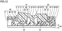
- Fig. 12 is a schematic vertical cross-sectional view illustrating a state of contact of pressing member 70 with contact 50.
- pressing member 70 When a user presses down key member 11 of key top 10 located on the right, pressing member 70 is moved downward. Pressing member 70 comes in contact with contact 50.
- pressing member 70 comes in contact with both of first contact portion 51 and second contact portion 52, a current flows between first contact portion 51 and second contact portion 52 through pressing member 70.
- Controller 100 thus senses the fact that the user has provided an input onto contact 50.
- central shaft 19 may come in contact with third surface 3 of substrate 30.
- Controller 100 thus senses the fact that the user stopped providing an input onto contact 50. While pressing member 70 is distant from contact 50, central shaft 19 may be distant from third surface 3 of substrate 30.
- Key top 10 swings around swing center 18. As shown in Fig. 12 , as right key member 11 moves downward, left key member 11 moves upward. In contrast, as left key member 11 moves downward, right key member 11 moves upward.
- Fig. 13 is a schematic vertical cross-sectional view illustrating an exemplary position of rib 80 when key top 10 is pressed down.
- a position of rib 80 when key top 10 is pressed down is shown with a solid line.
- a position of rib 80 when key top 10 is not pressed down is shown with a dashed line.
- each of inner rib portion 81 and outer rib portion 82 may be constructed such that the distance between substrate 30 and inner rib portion 81 is equal to the distance between substrate 30 and outer rib portion 82 when key top 10 is pressed down.
- a distance (an eighth distance D8) between third surface 3 of substrate 30 and inner rib portion 81 may be equal to a distance (a ninth distance D9) between third surface 3 of substrate 30 and outer rib portion 82.
- controller 100 according to the first embodiment is, for example, a game controller for performing an operation in a game, the controller is not limited to the game controller. Controller 100 according to the first embodiment may be a controller for performing an operation for information processing other than the game. Controller 100 according to the first embodiment may be, for example, a controller for information processing for performing an operation for moving a cursor or selecting a menu.
- the distance between the end of the outer peripheral edge (first inner end 65) of prescribed region 63 on the side of swing center 18 of key top 10 and the end (second inner end 75) of top surface 71 on the side of swing center 18 is longer than the distance between the end of the outer peripheral edge (first outer end 66) of prescribed region 63 opposite to swing center 18 and the end (second outer end 76) of top surface 71 opposite to swing center 18.
- pressing member 70 is provided on the outer side in prescribed region 63 of pressed portion 23. Therefore, a radius of rotation of pressing member 70 can be larger than when pressing member 70 is provided on the inner side in prescribed region 63 of pressed portion 23. Consequently, pressing member 70 can more linearly be lowered. Therefore, the area of contact between pressing member 70 and contact 50 can be made larger.
- Controller 100 can more effectively secure a large area of contact between pressing member 70 and contact 50 when key top 10 is reduced in size.
- a central position of pressing member 70 may be displaced from a central position of contact 50. In this case, contact sensitivity between pressing member 70 and contact 50 may be lowered.
- contact 50 is located closer to swing center 18 than pressing member 70. Therefore, when pressing member 70 is shifted inward, the central position of pressing member 70 moves in a direction toward the central position of contact 50. Therefore, displacement of the central position of pressing member 70 from the central position of contact 50 can be suppressed. Consequently, lowering in contact sensitivity between pressing member 70 and contact 50 can further be suppressed.
- pressing member 70 In order to address the problem of inward rotation of pressing member 70, a construction in which contact 50 is located on the radially inner side is also possible. By locating pressing member 70 on the radially outer side, however, pressing member 70 can more linearly be lowered. By increasing a diameter of pressing member 70 without changing the central position of pressing member 70 as well, pressing member 70 can extend radially outward. Increase in diameter of pressing member 70, however, may lead to tendency of an erroneous input as will be described later. Therefore, occurrence of an erroneous input can be suppressed by setting a diameter of pressing member 70 to moderate magnitude.
- Fig. 18 is a schematic plan view illustrating a state of the controller when position displacement of key top 10 in a direction of rotation occurs.
- key top 10 since there is a gap between first inner wall surface 43 and key top 10, key top 10 may move in a direction of rotation B.
- pressing member 70 located at 0° may be in contact with both of contact 50 located at 0° and contact 50 located at 90°.
- Pressing member 70 is formed in elastic member 20. Therefore, when elastic member 20 is deformed, pressing member 70 may be inclined. An erroneous input may be provided also in this case.
- key top 10 may include rib 80 that surrounds at least a part of the outer circumferential side surface of pressed portion 23.
- rib 80 may include outer rib portion 82 and inner rib portion 81 provided closer to swing center 18 than outer rib portion 82. In the direction in parallel to first direction 101, inner rib portion 81 may be larger in height than outer rib portion 82.
- Outer rib portion 82 is larger in radius of rotation than inner rib portion 81. Therefore, when outer rib portion 82 is equal in height to inner rib portion 81, outer rib portion 82 is located below inner rib portion 81 at the time of pressing of key top 10. Therefore, outer rib portion 82 may interfere with skirt portion 24 more than inner rib portion 81. By setting inner rib portion 81 to be higher than outer rib portion 82, interference of outer rib portion 82 with skirt portion 24 can be suppressed while inner rib portion 81 securely holds pressed portion 23.
- rib 80 in the direction in parallel to first direction 101, may increase in height from outer rib portion 82 toward inner rib portion 81.
- rib 80 can more securely be attached to pressed portion 23 while interference of rib 80 with skirt portion 24 is suppressed.
- a direction being in parallel to second direction 102 and extending radially from swing center 18 is defined as the radial direction.
- a clearance between the outer circumferential side surface and rib 80 in third direction 103 that passes through the center of rib 80 and is perpendicular to the radial direction may be smaller than a clearance between the outer circumferential side surface and rib 80 in the radial direction that passes through the center of rib 80.
- Controller 100 according to the second embodiment is different from controller 100 according to the first embodiment mainly in that a shape of the upper surface of key top 10 is substantially rectangular, and it is otherwise similar to controller 100 according to the first embodiment. Description will be given below with a difference from controller 100 according to the first embodiment being focused on.
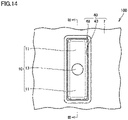
- Fig. 14 is a schematic plan view illustrating a construction of controller 100 according to the second embodiment.
- the upper surface (fifth surface 5) of key top 10 may be in a substantially rectangular shape.
- Key top 10 may include, for example, two key members 11. When two key members 11 are provided, two pressing members 70 may be provided. When two key members 11 are provided, two sets of contacts 50 may be provided.
- the schematic vertical cross-sectional view along the line III-III in Fig. 14 is shown in Fig. 3 .
- the schematic vertical cross-sectional view of controller 100 according to the second embodiment is substantially the same as the schematic cross-sectional view of controller 100 according to the first embodiment.
- the number of key members 11 is not limited to two.
- a single key member 11 may be provided.
- one end of key top 10 serves as a fulcrum and the other end of key top 10 serves as key member 11.
- Pivot of key member 11 around the fulcrum is herein also defined as swing.
- the fulcrum corresponds to swing center 18.
- a direction from the fulcrum toward key member 11 corresponds to the radial direction.
- a single pressing member 70 may be provided.
- Controller 100 according to the third embodiment is different from controller 100 according to the first embodiment mainly in that four contact portions are included in one set of contacts 50, and it is otherwise similar to controller 100 according to the first embodiment. Description will be given below with a difference from controller 100 according to the first embodiment being focused on.
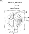
- Fig. 15 is a schematic plan view illustrating a construction of contact 50 of controller 100 according to the third embodiment.
- contact 50 may include first contact portion 51, second contact portion 52, a third contact portion 53, and a fourth contact portion 54.
- first contact portion 51, second contact portion 52, third contact portion 53, and fourth contact portion 54 may be in a shape of a sector.
- a central angle of first contact portion 51 may be larger than a central angle of third contact portion 53.
- a central angle of second contact portion 52 may be larger than a central angle of fourth contact portion 54.
- First contact portion 51, second contact portion 52, third contact portion 53, and fourth contact portion 54 are distant from one another.
- third contact portion 53 may be located on the outer side relative to first contact portion 51.
- fourth contact portion 54 may be located on the outer side relative to second contact portion 52.
- first contact portion 51 and the shape of second contact portion 52 may be in line symmetry to each other.
- shape of third contact portion 53 and the shape of fourth contact portion 54 may be in line symmetry to each other.
- top surface 71 of pressing member 70 may be arranged to overlap with each of first contact portion 51, second contact portion 52, third contact portion 53, and fourth contact portion 54.
- prescribed region 63 of pressed portion 23 may be arranged to overlap with each of first contact portion 51, second contact portion 52, third contact portion 53, and fourth contact portion 54.
- Controller 100 according to the third embodiment is advantageous similarly to controller 100 according to the first embodiment.
- Fig. 16 is a schematic plan view illustrating a construction of a modification of the controller.
- controller 100 may include an operation button 90.
- Housing 40 is provided with first through hole 49 and a second through hole 45.
- Key top 10 is arranged in first through hole 49.
- Operation button 90 is arranged in second through hole 45.
- Operation button 90 may be surrounded by a second inner wall surface 44 that defines second through hole 45.
- operation button 90 When viewed in first direction 101, operation button 90 may be, for example, in a circular shape, although the shape thereof is not particularly limited.
- housing 40 When viewed in first direction 101, housing 40 may be, for example, in a rectangular shape, although the shape thereof is not particularly limited.
- Controller 100 may further include a storage (not shown) and/or a processor (not shown) and/or a display (not shown).
- a dynamic random access memory DRAM
- An application program such as a game may be stored in the storage.
- the processor may read the application program and perform information processing.
- the display may show, for example, an image generated as a result of information processing performed by the processor.
- Controller 100 may include the storage, the processor, and the display, and controller 100 alone may function as a game console.
- Controller 100 may be controller 100 separate from a game console main body (not shown). Controller 100 may include a communication unit (not shown). Controller 100 may be connected to the game console main body through the communication unit. The communication unit may transmit and receive data over a wireless signal. The communication unit may support such a communication scheme as Bluetooth ® or infrared communication. Controller 100 may be controller 100 for operating a game device or controller 100 for operating an information processing apparatus different from a game device.
- Fig. 17 is a schematic vertical cross-sectional view illustrating a construction of a key structure.
- a key structure 200 includes key top 10 and elastic member 20. The structure of each of key top 10 and elastic member 20 is as described above. In Fig. 17 , the same components in key top 10 and elastic member 20 have the same reference numerals allotted and description thereof will not be provided.
Landscapes
- Engineering & Computer Science (AREA)
- Multimedia (AREA)
- Human Computer Interaction (AREA)
- General Engineering & Computer Science (AREA)
- Theoretical Computer Science (AREA)
- Physics & Mathematics (AREA)
- General Physics & Mathematics (AREA)
- Switches With Compound Operations (AREA)
Abstract
Description
- The present disclosure relates to a controller and a key structure.
-
Japanese Patent Laying-Open No. 8-77885 - A controller according to the present disclosure includes a key top, a substrate, and an elastic member. The elastic member is provided between the key top and the substrate. The elastic member includes a pressed portion pressed as the key top swings, a base in contact with the substrate, a skirt portion that connects the pressed portion and the base to each other and is elastically deformed as the pressed portion is pressed, and a pressing member provided in a prescribed region that is a part of the pressed portion, is opposed to the substrate, and is surrounded by the skirt portion, at least a top surface of the pressing member opposed to the substrate being conductive. The top surface is constructed to press a contact as the skirt portion is elastically deformed. The substrate includes the contact at a position pressed by the top surface. A direction in which the key top and the elastic member are layered is defined as a first direction. A direction perpendicular to the first direction is defined as a second direction. When viewed in the first direction, the pressing member is surrounded by an outer peripheral edge of the prescribed region. In the second direction, a distance between an end of the outer peripheral edge of the prescribed region on a side of a swing center of the key top and an end of the top surface on the side of the swing center is longer than a distance between an end of the outer peripheral edge of the prescribed region opposite to the swing center and an end of the top surface opposite to the swing center. In the second direction, the contact is located closer to the swing center than the top surface.
- In operating the key top, the key top may rotate inward. When the key top rotates inward, the pressing member is also lowered while being rotated inward. Therefore, the pressing member is inclined with respect to the surface of the contact. Consequently, an area of contact between the pressing member and the contact becomes smaller. In this case, contact sensitivity between the pressing member and the contact may become lower.
- According to the controller, in the second direction, the distance between the end of the outer peripheral edge (a first inner end) of the prescribed region on the side of the swing center of the key top and the end (a second inner end) of the top surface on the side of the swing center is longer than the distance between the end of the outer peripheral edge (a first outer end) of the prescribed region opposite to the swing center and the end (a second outer end) of the top surface opposite to the swing center. In other words, the pressing member is provided on an outer side in the prescribed region of the pressed portion. Therefore, a radius of rotation of the pressing member can be larger than when the pressing member is provided on an inner side in the prescribed region of the pressed portion. Consequently, the pressing member can more linearly be lowered. Therefore, the area of contact between the pressing member and the contact can be made larger. Therefore, lowering in contact sensitivity between the pressing member and the contact can be suppressed.
- When a key pad is reduced in size, the distance from the swing center to the pressing member becomes shorter. In this case, the radius of rotation of the pressing member becomes smaller and hence the pressing member tends to be lowered while being rotated. Therefore, the area of contact between the pressing member and the contact tends to be small. The controller according to the present disclosure can more effectively secure a large area of contact between the pressing member and the contact when the key top is reduced in size.
- In operating the key top, when the pressing member is shifted inward, a central position of the pressing member may be displaced from a central position of the contact. In this case, contact sensitivity between the pressing member and the contact may be lowered.
- According to the controller, in the second direction, the contact is located closer to the swing center than the pressing member. Therefore, when the pressing member is shifted inward, the central position of the pressing member moves in a direction toward the central position of the contact. Therefore, displacement of the central position of the pressing member from the central position of the contact can be suppressed. Consequently, lowering in contact sensitivity between the pressing member and the contact can further be suppressed.
- In the controller, the key top may include a rib that surrounds at least a part of an outer circumferential side surface of the pressed portion.
- According to this construction, displacement of the key top in a direction of rotation from the elastic member can be suppressed. The elastic member is fixed with respect to the substrate. Therefore, displacement of the key top in the direction of rotation from the contact arranged on the substrate can be suppressed. Consequently, occurrence of an erroneous input due to displacement of the key top in the direction of rotation can be suppressed.
- In the controller, the rib may include an outer rib portion and an inner rib portion provided closer to the swing center than the outer rib portion. In a direction in parallel to the first direction, the inner rib portion may be larger in height than the outer rib portion.
- The outer rib portion is larger in radius of rotation than the inner rib portion. Therefore, when the outer rib portion is equal in height to the inner rib portion, the outer rib portion is located below the inner rib portion at the time of pressing of the key top. Therefore, the outer rib portion may interfere with the skirt portion more than the inner rib portion. By setting the height of the inner rib portion to be larger than the height of the outer rib portion, interference of the outer rib portion with the skirt portion can be suppressed while the inner rib portion securely holds the pressed portion.
- In the controller, in the direction in parallel to the first direction, the rib may increase in height from the outer rib portion toward the inner rib portion.
- According to this construction, the rib can more securely be attached to the pressed portion while interference of the rib with the skirt portion is suppressed.
- In the controller, each of the inner rib portion and the outer rib portion may be constructed such that, when the key top is pressed down, a distance between the substrate and the inner rib portion is equal to a distance between the substrate and the outer rib portion.
- In the controller, a direction being in parallel to the second direction and extending radially from the swing center is defined as a radial direction. When viewed in the first direction, a clearance between the outer circumferential side surface and the rib in a third direction that passes through a center of the rib and is perpendicular to the radial direction may be smaller than a clearance between the outer circumferential side surface and the rib in the radial direction that passes through the center of the rib.
- According to this construction, by reducing the clearance between the outer circumferential side surface and the rib in the third direction, displacement of the key top in the direction of rotation from the elastic member can further be suppressed. By increasing the clearance between the outer circumferential side surface and the rib in the radial direction, the rib can readily be attached to the pressed portion.
- In the controller, the rib may include an inner circumferential surface and a protrusion that protrudes from the inner circumferential surface in the third direction.
- In the controller, when viewed in the first direction, the key top may be in a cross shape.
- A key structure according to the present disclosure includes a key top and an elastic member. The elastic member is opposed to the key top. The elastic member includes a pressed portion pressed as the key top swings, a base distant from the pressed portion, a skirt portion that connects the pressed portion and the base to each other and is elastically deformed as the pressed portion is pressed, and a pressing member provided in a prescribed region that is a part of the pressed portion and is surrounded by the skirt portion, at least a top surface of the pressing member being conductive. A direction in which the key top and the elastic member are layered is defined as a first direction. A direction perpendicular to the first direction is defined as a second direction. When viewed in the first direction, the pressing member is surrounded by an outer peripheral edge of the prescribed region. In the second direction, a distance between an end of the outer peripheral edge of the prescribed region on a side of a swing center of the key top and an end of the top surface on the side of the swing center is longer than a distance between an end of the outer peripheral edge of the prescribed region opposite to the swing center and an end of the top surface opposite to the swing center.
- According to the key structure, in the second direction, the distance between the end of the outer peripheral edge (a first inner end) of the prescribed region on the side of the swing center of the key top and the end (a second inner end) of the top surface on the side of the swing center is longer than the distance between the end of the outer peripheral edge (a first outer end) of the prescribed region opposite to the swing center and the end (a second outer end) of the top surface opposite to the swing center. In other words, the pressing member is provided on the outer side in the prescribed region of the pressed portion. Therefore, a radius of rotation of the pressing member can be larger than when the pressing member is provided on the inner side in the prescribed region of the pressed portion. Consequently, the pressing member can more linearly be lowered. Consequently, the area of contact between the pressing member and the contact can be made larger. Therefore, lowering in contact sensitivity between the pressing member and the contact can be suppressed.
- In the key structure, the key top may include a rib that surrounds at least a part of an outer circumferential side surface of the pressed portion.
- According to this construction, displacement of the key top in a direction of rotation from the elastic member can be suppressed. The elastic member is fixed with respect to the substrate. Therefore, displacement of the key top in the direction of rotation from the contact arranged on the substrate can be suppressed. Consequently, occurrence of an erroneous input due to displacement of the key top in the direction of rotation can be suppressed.
- In the key structure, the rib may include an outer rib portion and an inner rib portion provided closer to the swing center than the outer rib portion. In a direction in parallel to the first direction, the inner rib portion may be larger in height than the outer rib portion.
- The outer rib portion is larger in radius of rotation than the inner rib portion. Therefore, when the outer rib portion is equal in height to the inner rib portion, the outer rib portion is located below the inner rib portion at the time of pressing of the key top. Therefore, the outer rib portion may interfere with the skirt portion more than the inner rib portion. By setting the height of the inner rib portion to be larger than the height of the outer rib portion, interference of the outer rib portion with the skirt portion can be suppressed while the inner rib portion securely holds the pressed portion.
- In the key structure, in the direction in parallel to the first direction, the rib may increase in height from the outer rib portion toward the inner rib portion.
- According to this construction, the rib can more securely be attached to the pressed portion while interference of the rib with the skirt portion is suppressed.
- In the key structure, a direction being in parallel to the second direction and extending radially from the swing center is defined as a radial direction. When viewed in the first direction, a clearance between the outer circumferential side surface and the rib in a third direction that passes through a center of the rib and is perpendicular to the radial direction may be smaller than a clearance between the outer circumferential side surface and the rib in the radial direction that passes through the center of the rib.
- According to this construction, by reducing the clearance between the outer circumferential side surface and the rib in the third direction, displacement of the key top in the direction of rotation from the elastic member can further be suppressed. By increasing the clearance between the outer circumferential side surface and the rib in the radial direction, the rib can readily be attached to the pressed portion.
- In the key structure, the rib may include an inner circumferential surface and a protrusion that protrudes from the inner circumferential surface in the third direction.
- In the key structure, when viewed in the first direction, the key top may be in a cross shape.
- The foregoing and other objects, features, aspects and advantages of the exemplary embodiments will become more apparent from the following detailed description of the exemplary embodiments when taken in conjunction with the accompanying drawings.
-
-
Fig. 1 shows an exemplary illustrative non-limiting exploded schematic perspective view illustrating a construction of a controller according to a first embodiment. -
Fig. 2 shows an exemplary illustrative non-limiting schematic plan view illustrating the construction of the controller according to the first embodiment. -
Fig. 3 shows an exemplary illustrative non-limiting schematic vertical cross-sectional view along the line III-III inFig. 2 . -
Fig. 4 shows an exemplary illustrative non-limiting enlarged schematic vertical cross-sectional view of a region IV inFig. 3 . -
Fig. 5 shows an exemplary illustrative non-limiting schematic bottom view illustrating a construction of a key top when viewed from a side of a sixth surface. -
Fig. 6 shows an exemplary illustrative non-limiting schematic side view illustrating a construction of a rib. -
Fig. 7 shows an exemplary illustrative non-limiting schematic lateral cross-sectional view illustrating a clearance between the rib and a pressed portion. -
Fig. 8 shows an exemplary illustrative non-limiting schematic perspective view illustrating a construction of the key top and an elastic member. -
Fig. 9 shows an exemplary illustrative non-limiting schematic plan view illustrating a construction of the elastic member. -
Fig. 10 shows an exemplary illustrative non-limiting enlarged schematic plan view of a region X inFig. 9 . -
Fig. 11 shows an exemplary illustrative non-limiting schematic plan view illustrating positional relation between a contact and a top surface of a pressing member. -
Fig. 12 shows an exemplary illustrative non-limiting schematic vertical cross-sectional view illustrating a state of contact of the pressing member with the contact. -
Fig. 13 shows an exemplary illustrative non-limiting schematic vertical cross-sectional view illustrating an exemplary position of the rib when the key top is pressed down. -
Fig. 14 shows an exemplary illustrative non-limiting schematic plan view illustrating a construction of the controller according to a second embodiment. -
Fig. 15 shows an exemplary illustrative non-limiting schematic plan view illustrating a construction of the contact of the controller according to a third embodiment. -
Fig. 16 shows an exemplary illustrative non-limiting schematic plan view illustrating a construction of a modification of the controller. -
Fig. 17 shows an exemplary illustrative non-limiting schematic vertical cross-sectional view illustrating a construction of a key structure. -
Fig. 18 shows an exemplary illustrative non-limiting schematic plan view illustrating a state of the controller when position displacement of the key top in a direction of rotation occurs. - An embodiment of the present disclosure will be described in detail with reference to the drawings. The same or corresponding elements in the drawings have the same reference characters allotted and description thereof will not be repeated.
- Overview of a construction of a
controller 100 according to a first embodiment of the present disclosure will initially be described. -
Fig. 1 is an exploded schematic perspective view illustrating a construction ofcontroller 100 according to the first embodiment. As shown inFig. 1 ,controller 100 according to the first embodiment mainly includes ahousing 40, a key top 10, anelastic member 20, and asubstrate 30.Housing 40 includes aseventh surface 7, aneighth surface 8, a firstinner wall surface 43, a first fixingportion 41, asecond fixing portion 42, and a firstannular member 48.Eighth surface 8 is located opposite toseventh surface 7.Housing 40 is provided with a first throughhole 49. First throughhole 49 is defined by firstinner wall surface 43. First throughhole 49 opens in each ofseventh surface 7 andeighth surface 8.Eighth surface 8 is opposed tosubstrate 30.Eighth surface 8 is provided with first fixingportion 41, second fixingportion 42, and firstannular member 48. - Key top 10 includes a
fifth surface 5, asixth surface 6, akey member 11, and a projectingportion 12.Sixth surface 6 is located opposite tofifth surface 5. A recess may be provided in acentral portion 13 offifth surface 5.Key member 11 may extend in four directions fromcentral portion 13. For example, fourkey members 11 are provided.Key member 11 definesfifth surface 5. Projectingportion 12 is contiguous tokey member 11. Projectingportion 12 may extend outward fromkey member 11. Projectingportion 12 definessixth surface 6. Key top 10 is made, for example, of a resin. -
Elastic member 20 includes afirst surface 1, asecond surface 2, a pressedportion 23, and a secondannular member 26.First surface 1 is opposed tosubstrate 30.Second surface 2 is located opposite tofirst surface 1.Second surface 2 is opposed to key top 10. Pressedportion 23 is provided onsecond surface 2 as protruding. For example, four pressedportions 23 are provided. Acentral hole 22 is provided inelastic member 20.Central hole 22 opens in each offirst surface 1 andsecond surface 2. Pressedportion 23 is arranged aroundcentral hole 22. - Pressed
portion 23 is provided at a position opposed tokey member 11. Secondannular member 26 may be provided in an outer circumferential portion ofsecond surface 2. Secondannular member 26 surrounds pressedportions 23.Elastic member 20 is provided with a fixinghole 21. Fixinghole 21 opens in each offirst surface 1 andsecond surface 2. Fixinghole 21 is provided on an outer side of secondannular member 26.Central hole 22 is provided on an inner side of secondannular member 26. -
Substrate 30 includes athird surface 3 and a fourth surface 4. Acontact 50 is provided onthird surface 3. For example, four sets ofcontacts 50 are provided.Contact 50 is provided at a position opposed to pressedportion 23. For example, two conductive contact portions are included in onecontact 50.Substrate 30 may be provided with afirst hole 31 and asecond hole 32. First fixingportion 41 is inserted in fixinghole 21 and positioned abovefirst hole 31. Second fixingportion 42 is positioned abovesecond hole 32. -
Fig. 2 is a schematic plan view illustrating the construction ofcontroller 100 according to the first embodiment. The schematic plan view inFig. 2 shows a state thathousing 40, key top 10,elastic member 20, andsubstrate 30 shown inFig. 1 are assembled. As shown inFig. 2 , in the plan view, key top 10 may be, for example, in a cross shape. Key top 10 is arranged in a region surrounded by firstinner wall surface 43 ofhousing 40. A gap (in other words, a clearance) is provided between firstinner wall surface 43 andkey member 11 of key top 10. The clearance is set, for example, to 0.45 mm. The clearance may be not smaller than 0.3 mm and not larger than 0.6 mm. - As shown in
Fig. 2 , in the plan view, key top 10 has a width (a first width W1), for example, of 17 mm. An upper limit of first width W1 may be, for example, not larger than 20 mm or not larger than 18 mm, although it is not particularly limited. A lower limit of first width W1 may be, for example, not smaller than 10 mm or not smaller than 12 mm, although it is not particularly limited. As shown inFig. 2 , a width (a second width W2) of first throughhole 49 is larger than first width W1. First width W1 may be a width offifth surface 5 in the radial direction. -
Fig. 3 is a schematic vertical cross-sectional view along the line III-III inFig. 2 . As shown inFig. 3 , a part of key top 10 is arranged in first throughhole 49.Fifth surface 5 of key top 10 is located outsidehousing 40.Fifth surface 5 is, for example, a surface touched by a finger of a user.Sixth surface 6 is a surface opposed toelastic member 20.Sixth surface 6 may be in contact withelastic member 20.Sixth surface 6 may be located withinhousing 40. Projectingportion 12 of key top 10 may be in contact witheighth surface 8 ofhousing 40. - As shown in
Fig. 3 , key top 10 includes acentral shaft 19.Key member 11 may be contiguous tocentral shaft 19.Key member 11 is provided aroundcentral shaft 19.Key member 11 is provided on each of opposing sides ofcentral shaft 19. The number ofkey members 11 is not particularly limited. One key member, 11, twokey members 11, fourkey members 11, or eightkey members 11 may be provided.Fifth surface 5 in the cross shape of key top 10 is exposed as protruding throughhousing 40. A part offifth surface 5 in the cross shape may be covered withhousing 40. - As shown in
Fig. 3 ,elastic member 20 is provided between key top 10 andsubstrate 30. A direction from key top 10 towardelastic member 20 herein is defined as a downward direction. A direction fromelastic member 20 toward key top 10 is defined as an upward direction.Elastic member 20 is in contact with key top 10.Elastic member 20 biases key top 10 upward. When a user applies downward force tokey member 11,elastic member 20 is pressed down bykey member 11. When the user is not applying downward force to key member 11 (that is, when the user is not touching key member 11),key member 11 is pushed upward by repulsive force ofelastic member 20. -
Central shaft 19 of key top 10 may be inserted incentral hole 22 inelastic member 20. Firstannular member 48 is fitted to secondannular member 26. An outer circumferential surface of firstannular member 48 is in contact with an inner circumferential surface of secondannular member 26. Firstannular member 48 may be in contact withsecond surface 2 ofelastic member 20. When viewed fromelastic member 20,substrate 30 is arranged opposite to key top 10.Third surface 3 ofsubstrate 30 is opposed tofirst surface 1 ofelastic member 20. A part ofthird surface 3 ofsubstrate 30 is in contact with a part offirst surface 1 ofelastic member 20.Substrate 30 includescontact 50.Contact 50 is provided onthird surface 3.Contact 50 may be provided at a position opposed to pressedportion 23.Contact 50 may be provided belowkey member 11. - As shown in
Fig. 3 ,key member 11 of key top 10 is arranged on each of opposing sides ofcentral shaft 19. When one of twokey members 11 is pressed down, the other of twokey members 11 is pushed up. In contrast, when the other of twokey members 11 is pressed down, one of twokey members 11 is pushed up. In other words, key top 10 can swing. Aswing center 18 of key top 10 is located, for example, incentral shaft 19. - A direction in parallel to a direction of layering of key top 10 and
elastic member 20 is herein defined as afirst direction 101.First direction 101 is the same as the direction of extension ofcentral shaft 19.First direction 101 is also referred to as an axial direction. A direction perpendicular tofirst direction 101 is defined as asecond direction 102. A direction being in parallel tosecond direction 102 and radially extending fromswing center 18 is defined as a radial direction. A plan view is a view in a direction alongfirst direction 101. A vertical cross-section is defined as a cross-section substantially in parallel tofirst direction 101. A lateral cross-section is defined as a cross-section substantially perpendicular tofirst direction 101. -
Fig. 4 is an enlarged schematic vertical cross-sectional view of a region IV inFig. 3 . As shown inFig. 4 ,elastic member 20 includes pressedportion 23, abase 29, askirt portion 24, and a pressingmember 70. Pressedportion 23 is pressed as key top 10 swings. Pressedportion 23 may include afirst member 61 and asecond member 62.First member 61 is contiguous tosecond member 62.First member 61 is provided belowsecond member 62.First member 61 is provided betweensecond member 62 and pressingmember 70.First member 61 is provided on a side offirst surface 1.First member 61 forms a part offirst surface 1.Second member 62 is provided on a side ofsecond surface 2. In the radial direction,first member 61 may be smaller in width thansecond member 62.First member 61 may be surrounded byskirt portion 24. -
Base 29 is in contact withsubstrate 30.Base 29 is in contact withthird surface 3 ofsubstrate 30.Base 29 forms a part of each offirst surface 1 andsecond surface 2.Skirt portion 24 connects pressedportion 23 andbase 29 to each other.Skirt portion 24 is contiguous tosecond member 62 of pressedportion 23.Skirt portion 24 is contiguous tobase 29.Skirt portion 24 is elastically deformed as pressedportion 23 is pressed.Skirt portion 24 is tapered frombase 29. From a different point of view,skirt portion 24 is tapered upward. - Upward biasing force may be applied to key top 10 by
skirt portion 24. Pressedportion 23 is in contact with key top 10.Skirt portion 24 may be distant from key top 10. Pressedportion 23 includes a prescribedregion 63 opposed tosubstrate 30.Prescribed region 63 is surrounded byskirt portion 24. Pressingmember 70 is provided inprescribed region 63 of pressedportion 23. Pressingmember 70 may be provided within prescribedregion 63, for example, infirst member 61 of pressedportion 23 that protrudes towardsubstrate 30. - Pressed
portion 23 does not have to includefirst member 61. In this case, pressingmember 70 is provided insecond member 62. Pressingmember 70 includes atop surface 71 opposed tosubstrate 30.Contact 50 is arranged at a position pressed bytop surface 71 of pressingmember 70.Top surface 71 is constructed to pushcontact 50 asskirt portion 24 is elastically deformed.Top surface 71 may be opposed to contact 50. Pressingmember 70 can be in contact withcontact 50. - Each of pressed
portion 23,base 29, andskirt portion 24 is made, for example, of silicone. Each of pressedportion 23,base 29, andskirt portion 24 is insulating. Pressingmember 70 is made, for example, of carbon. Though entire pressingmember 70 does not have to be conductive, at leasttop surface 71 of pressingmember 70 is conductive. Pressingmember 70 may be formed integrally with pressedportion 23 or may be fixed to pressedportion 23 by an adhesive or the like. - As shown in
Fig. 4 , key top 10 includes arib 80.Rib 80 is provided belowkey top 10.Rib 80 protrudes downward from abottom surface 14 ofkey member 11.Bottom surface 14 is a surface in contact with pressedportion 23.Rib 80 surrounds at least a part of an outercircumferential side surface 27 of pressedportion 23.Rib 80 may surround the entire circumference of pressedportion 23.Rib 80 surrounds outercircumferential side surface 27 ofsecond member 62.Rib 80 may be provided not to surroundskirt portion 24.Rib 80 may be distant fromskirt portion 24. - As shown in
Fig. 4 ,rib 80 may include anouter rib portion 82 and aninner rib portion 81.Inner rib portion 81 is provided on a radially inner side relative toouter rib portion 82. As shown inFigs. 3 and4 ,inner rib portion 81 is located betweencentral shaft 19 andouter rib portion 82. In a direction in parallel tofirst direction 101,inner rib portion 81 may be larger in height thanouter rib portion 82. -
Fig. 5 is a schematic bottom view illustrating a construction of key top 10 when viewed from a side ofsixth surface 6. As shown inFig. 5 , when viewed infirst direction 101,key members 11 are arranged at regular intervals aroundcentral shaft 19. When viewed infirst direction 101, aroundswing center 18 that coincides withcentral shaft 19, a plurality ofkey members 11 are arranged, for example, at positions at 0°, 90°, 180°, and 270°. - A
recess 17 which is a space recessed upward may be provided inbottom surface 14 ofkey member 11.Rib 80 may include an innercircumferential surface 85 and aprotrusion 83.Protrusion 83 protrudes from innercircumferential surface 85 in athird direction 103.Third direction 103 is a direction that passes through a center ofrib 80 and is perpendicular to the radial direction when viewed in first direction 101 (seeFig. 7 ). Oneprotrusion 83 or twoprotrusions 83 may be provided. When twoprotrusions 83 are provided, twoprotrusions 83 may be opposed to each other. -
Fig. 6 is a schematic side view illustrating a construction ofrib 80. The side surface shown inFig. 6 is a side surface ofrib 80 viewed in the direction perpendicular to second direction 102 (radial direction). As shown inFig. 6 , the height ofrib 80 in the direction in parallel tofirst direction 101 increases towardinner rib portion 81 fromouter rib portion 82. The height ofrib 80 in the direction in parallel tofirst direction 101 may monotonously increase towardinner rib portion 81 fromouter rib portion 82. In second direction 102 (radial direction),inner rib portion 81 is located on an innermost side (the side of swing center 18). In second direction 102 (radial direction),outer rib portion 82 is located on an outermost side. - As shown in
Fig. 6 , infirst direction 101, the height (a first height HI) ofinner rib portion 81 is larger than the height (a second height H2) ofouter rib portion 82. A lower limit of first height HI may be, for example, at least 1.2 time or at least 1.5 time as large as second height H2, although it is not particularly limited. An upper limit of first height H1 may be, for example, at most five times or at most four times as large as second height H2, although it is not particularly limited. -
Fig. 7 is a schematic lateral cross-sectional view illustrating a clearance between the rib and pressedportion 23.Fig. 7 corresponds to a structure aroundkey member 11 located on an upper side inFig. 5 . As shown inFig. 7 , when viewed infirst direction 101, a clearance between pressedportion 23 andrib 80 inthird direction 103 may be smaller than a clearance between pressedportion 23 andrib 80 in the radial direction. As shown inFig. 7 , when viewed infirst direction 101, a distance (a first distance D1) between outercircumferential side surface 27 of pressedportion 23 and innercircumferential surface 85 ofrib 80 inthird direction 103 may be shorter than a distance (a second distance D2) between outercircumferential side surface 27 of pressedportion 23 and innercircumferential surface 85 ofrib 80 in the radial direction. First distance D1 is set, for example, to 0.01 mm. Second distance D2 is set, for example, to 0.05 mm. First distance D1 may be set to 0 mm. In other words, when viewed infirst direction 101, no clearance between pressedportion 23 andrib 80 inthird direction 103 may be provided. In this case as well, when viewed infirst direction 101, the clearance between pressedportion 23 andrib 80 inthird direction 103 can be concluded as being smaller than the clearance between pressedportion 23 andrib 80 in the radial direction. -
Fig. 8 is a schematic perspective view illustrating a construction of key top 10 andelastic member 20. As shown inFig. 8 ,second surface 2 ofelastic member 20 is opposed tosixth surface 6 of key top 10.Central shaft 19 of key top 10 is positioned atcentral hole 22 inelastic member 20. In the direction in parallel to the direction alongcentral shaft 19, the plurality ofkey members 11 are arranged as being superimposed ontop surfaces 71 of a plurality of pressingmembers 70, respectively. -
Fig. 9 is a schematic plan view illustrating a construction ofelastic member 20. As shown inFig. 9 , when viewed infirst direction 101, prescribedregions 63 of a plurality of pressedportions 23 are arranged at regular intervals aroundcentral hole 22. Aroundcentral hole 22, prescribedregions 63 of the plurality of pressedportions 23 are arranged, for example, at positions at 0°, 90°, 180°, and 270°. Similarly, when viewed infirst direction 101,top surfaces 71 of the plurality of pressingmembers 70 are arranged at regular intervals aroundcentral hole 22. Aroundcentral hole 22,top surfaces 71 of the plurality of pressingmembers 70 are arranged, for example, at positions at 0°, 90°, 180°, and 270°. The plurality of pressingmembers 70 are provided inprescribed regions 63 of the plurality of pressedportions 23, respectively. - As shown in
Fig. 9 , when viewed infirst direction 101, a plurality ofskirt portions 24 are arranged at regular intervals aroundcentral hole 22. Aroundcentral hole 22, the plurality ofskirt portions 24 are arranged, for example, at positions at 0°, 90°, 180°, and 270°. Infirst surface 1 ofelastic member 20, afirst connection groove 25 and asecond connection groove 28 are provided.First connection groove 25 connects spaces in two adjacentkey members 11 surrounded byelastic member 20 andsubstrate 30 to each other.Second connection groove 28 connects the space surrounded byelastic member 20 andsubstrate 30 inkey member 11 to an external space. -
Fig. 10 is an enlarged schematic plan view of a region X inFig. 9 . As shown inFigs. 9 and10 , when viewed infirst direction 101,top surface 71 of pressingmember 70 is surrounded by an outerperipheral edge 64 of prescribedregion 63. When viewed infirst direction 101, prescribedregion 63 is surrounded byskirt portion 24. Outerperipheral edge 64 of prescribedregion 63 is a boundary betweenskirt portion 24 andprescribed region 63. When viewed infirst direction 101, prescribedregion 63 is, for example, in a circular shape. When viewed infirst direction 101,top surface 71 of pressingmember 70 is, for example, in a circular shape. In the radial direction, a position of a center (a first center A1) oftop surface 71 of pressingmember 70 is different from a position of a center (a second center A2) of prescribedregion 63. First center A1 is located on a radially outer side relative to second center A2. From a different point of view, in the radial direction,top surface 71 of pressingmember 70 is eccentric with respect to prescribedregion 63. - In
second direction 102, a lower limit of a distance (a fifth distance D5) between first center A1 and second center A2 may be, for example, not shorter than 0.1 mm or not shorter than 0.2 mm, although it is not particularly limited. An upper limit of the distance (fifth distance D5) between first center A1 and second center A2 may be, for example, not longer than 1 mm or not longer than 0.5 mm, although it is not particularly limited. - Though prescribed
region 63 is, for example, in a circular shape, the shape thereof is not limited to the circular shape.Prescribed region 63 may be, for example, in an oval or polygonal shape. Similarly, thoughtop surface 71 is, for example, in a circular shape, the shape thereof is not limited to the circular shape. As shown inFig. 10 , insecond direction 102, a distance (a third distance D3) between an end of the outer peripheral edge (a first inner end 65) of prescribedregion 63 on the side ofswing center 18 and an end (a second inner end 75) oftop surface 71 on the side ofswing center 18 is longer than a distance (a fourth distance D4) between an end of the outer peripheral edge (a first outer end 66) of prescribedregion 63 opposite to swingcenter 18 and an end (a second outer end 76) oftop surface 71 opposite to swingcenter 18. A lower limit of fourth distance D4 may be, for example, not shorter than 0.05 mm or not shorter than 0.1 mm, although it is not particularly limited. An upper limit of fourth distance D4 may be, for example, not longer than 1 mm or not longer than 0.5 mm, although it is not particularly limited. A ratio between fourth distance D4 and third distance D3 may be accommodated within a range of ratios from 1:2 to 1:4. -
Fig. 11 is a schematic plan view illustrating positional relation betweencontact 50 andtop surface 71 of pressingmember 70. As shown inFig. 11 ,contact 50 includes, for example, afirst contact portion 51 and asecond contact portion 52.Contact 50 is conductive.Contact 50 is made, for example, of carbon. When viewed infirst direction 101, each offirst contact portion 51 andsecond contact portion 52 is, for example, in a semicircular shape.First contact portion 51 is distant fromsecond contact portion 52.First contact portion 51 andsecond contact portion 52 may be in line symmetry to each other. A center of a virtual circle including an arc portion offirst contact portion 51 and an arc portion ofsecond contact portion 52 is defined as a third center A3. When viewed infirst direction 101, third center A3 may coincide with second center A2. - As shown in
Fig. 11 , insecond direction 102, contact 50 is located closer to swingcenter 18 thantop surface 71. Specifically, insecond direction 102, third center A3 is located on a radially inner side relative to first center A1. From a different point of view, insecond direction 102, a distance (a sixth distance D6) between an end (a third inner end 55) ofcontact 50 on the side ofswing center 18 and an end (a second inner end 75) oftop surface 71 on the side ofswing center 18 may be longer than a distance (a seventh distance D7) between an end (a third outer end 56) ofcontact 50 opposite to swingcenter 18 and an end (a second outer end 76) oftop surface 71 opposite to swingcenter 18. -
Fig. 12 is a schematic vertical cross-sectional view illustrating a state of contact of pressingmember 70 withcontact 50. When a user presses downkey member 11 of key top 10 located on the right, pressingmember 70 is moved downward. Pressingmember 70 comes in contact withcontact 50. When pressingmember 70 comes in contact with both offirst contact portion 51 andsecond contact portion 52, a current flows betweenfirst contact portion 51 andsecond contact portion 52 through pressingmember 70.Controller 100 thus senses the fact that the user has provided an input ontocontact 50. When pressingmember 70 comes in contact withcontact 50,central shaft 19 may come in contact withthird surface 3 ofsubstrate 30. - As a finger of the user moves away from
key member 11 of key top 10,key member 11 moves upward owing to resilience ofskirt portion 24. Pressingmember 70 thus moves away fromcontact 50. As pressingmember 70 moves away fromcontact 50, no current flows betweenfirst contact portion 51 andsecond contact portion 52.Controller 100 thus senses the fact that the user stopped providing an input ontocontact 50. While pressingmember 70 is distant fromcontact 50,central shaft 19 may be distant fromthird surface 3 ofsubstrate 30. - Key top 10 swings around
swing center 18. As shown inFig. 12 , as rightkey member 11 moves downward, leftkey member 11 moves upward. In contrast, as leftkey member 11 moves downward, rightkey member 11 moves upward. -
Fig. 13 is a schematic vertical cross-sectional view illustrating an exemplary position ofrib 80 when key top 10 is pressed down. A position ofrib 80 when key top 10 is pressed down is shown with a solid line. A position ofrib 80 when key top 10 is not pressed down is shown with a dashed line. As shown inFig. 13 , each ofinner rib portion 81 andouter rib portion 82 may be constructed such that the distance betweensubstrate 30 andinner rib portion 81 is equal to the distance betweensubstrate 30 andouter rib portion 82 when key top 10 is pressed down. Specifically, when key top 10 is pressed down, a distance (an eighth distance D8) betweenthird surface 3 ofsubstrate 30 andinner rib portion 81 may be equal to a distance (a ninth distance D9) betweenthird surface 3 ofsubstrate 30 andouter rib portion 82. - Though
controller 100 according to the first embodiment is, for example, a game controller for performing an operation in a game, the controller is not limited to the game controller.Controller 100 according to the first embodiment may be a controller for performing an operation for information processing other than the game.Controller 100 according to the first embodiment may be, for example, a controller for information processing for performing an operation for moving a cursor or selecting a menu. - According to
controller 100 in the first embodiment, insecond direction 102, the distance between the end of the outer peripheral edge (first inner end 65) of prescribedregion 63 on the side ofswing center 18 of key top 10 and the end (second inner end 75) oftop surface 71 on the side ofswing center 18 is longer than the distance between the end of the outer peripheral edge (first outer end 66) of prescribedregion 63 opposite to swingcenter 18 and the end (second outer end 76) oftop surface 71 opposite to swingcenter 18. In other words, pressingmember 70 is provided on the outer side inprescribed region 63 of pressedportion 23. Therefore, a radius of rotation of pressingmember 70 can be larger than when pressingmember 70 is provided on the inner side inprescribed region 63 of pressedportion 23. Consequently, pressingmember 70 can more linearly be lowered. Therefore, the area of contact between pressingmember 70 andcontact 50 can be made larger. - Therefore, lowering in contact sensitivity between pressing
member 70 andcontact 50 can be suppressed. - When a key pad is reduced in size, the distance from
swing center 18 to pressingmember 70 becomes shorter. In this case, the radius of rotation of pressingmember 70 becomes smaller and hence pressingmember 70 tends to be lowered while being rotated. Therefore, the area of contact between pressingmember 70 andcontact 50 tends to be small.Controller 100 according to the present disclosure can more effectively secure a large area of contact between pressingmember 70 andcontact 50 when key top 10 is reduced in size. - In operating key top 10, when pressing
member 70 is shifted inward, a central position of pressingmember 70 may be displaced from a central position ofcontact 50. In this case, contact sensitivity between pressingmember 70 andcontact 50 may be lowered. - According to
controller 100 in the first embodiment, insecond direction 102, contact 50 is located closer to swingcenter 18 than pressingmember 70. Therefore, when pressingmember 70 is shifted inward, the central position of pressingmember 70 moves in a direction toward the central position ofcontact 50. Therefore, displacement of the central position of pressingmember 70 from the central position ofcontact 50 can be suppressed. Consequently, lowering in contact sensitivity between pressingmember 70 andcontact 50 can further be suppressed. - In order to address the problem of inward rotation of pressing
member 70, a construction in whichcontact 50 is located on the radially inner side is also possible. By locating pressingmember 70 on the radially outer side, however, pressingmember 70 can more linearly be lowered. By increasing a diameter of pressingmember 70 without changing the central position of pressingmember 70 as well, pressingmember 70 can extend radially outward. Increase in diameter of pressingmember 70, however, may lead to tendency of an erroneous input as will be described later. Therefore, occurrence of an erroneous input can be suppressed by setting a diameter of pressingmember 70 to moderate magnitude. -
Fig. 18 is a schematic plan view illustrating a state of the controller when position displacement of key top 10 in a direction of rotation occurs. As shown inFig. 18 , since there is a gap between firstinner wall surface 43 and key top 10, key top 10 may move in a direction of rotation B. In this case, for example, pressingmember 70 located at 0° may be in contact with both ofcontact 50 located at 0° andcontact 50 located at 90°. Thus, when key top 10 is pressed, an unintended oblique input may be provided. Pressingmember 70 is formed inelastic member 20. Therefore, whenelastic member 20 is deformed, pressingmember 70 may be inclined. An erroneous input may be provided also in this case. - In
controller 100 according to the first embodiment, key top 10 may includerib 80 that surrounds at least a part of the outer circumferential side surface of pressedportion 23. - According to this construction, displacement of key top 10 in a direction of rotation from
elastic member 20 can be suppressed.Elastic member 20 is fixed with respect tosubstrate 30. Therefore, displacement of key top 10 in the direction of rotation fromcontact 50 arranged onsubstrate 30 can be suppressed. Consequently, occurrence of an erroneous input due to displacement of key top 10 in the direction of rotation can be suppressed. - In
controller 100 according to the first embodiment,rib 80 may includeouter rib portion 82 andinner rib portion 81 provided closer to swingcenter 18 thanouter rib portion 82. In the direction in parallel tofirst direction 101,inner rib portion 81 may be larger in height thanouter rib portion 82. -
Outer rib portion 82 is larger in radius of rotation thaninner rib portion 81. Therefore, whenouter rib portion 82 is equal in height toinner rib portion 81,outer rib portion 82 is located belowinner rib portion 81 at the time of pressing of key top 10. Therefore,outer rib portion 82 may interfere withskirt portion 24 more thaninner rib portion 81. By settinginner rib portion 81 to be higher thanouter rib portion 82, interference ofouter rib portion 82 withskirt portion 24 can be suppressed whileinner rib portion 81 securely holds pressedportion 23. - In
controller 100 according to the first embodiment, in the direction in parallel tofirst direction 101,rib 80 may increase in height fromouter rib portion 82 towardinner rib portion 81. - According to this construction,
rib 80 can more securely be attached to pressedportion 23 while interference ofrib 80 withskirt portion 24 is suppressed. - In
controller 100 according to the first embodiment, a direction being in parallel tosecond direction 102 and extending radially fromswing center 18 is defined as the radial direction. When viewed infirst direction 101, a clearance between the outer circumferential side surface andrib 80 inthird direction 103 that passes through the center ofrib 80 and is perpendicular to the radial direction may be smaller than a clearance between the outer circumferential side surface andrib 80 in the radial direction that passes through the center ofrib 80. - According to this construction, by reducing the clearance between the outer circumferential side surface and
rib 80 inthird direction 103, displacement of key top 10 in the direction of rotation fromelastic member 20 can further be suppressed. By increasing the clearance between the outer circumferential side surface andrib 80 in the radial direction,rib 80 can readily be attached to pressedportion 23. - A construction of
controller 100 according to a second embodiment of the present disclosure will now be described.Controller 100 according to the second embodiment is different fromcontroller 100 according to the first embodiment mainly in that a shape of the upper surface of key top 10 is substantially rectangular, and it is otherwise similar tocontroller 100 according to the first embodiment. Description will be given below with a difference fromcontroller 100 according to the first embodiment being focused on. -
Fig. 14 is a schematic plan view illustrating a construction ofcontroller 100 according to the second embodiment. As shown inFig. 14 , when viewed infirst direction 101, the upper surface (fifth surface 5) of key top 10 may be in a substantially rectangular shape. Key top 10 may include, for example, twokey members 11. When twokey members 11 are provided, two pressingmembers 70 may be provided. When twokey members 11 are provided, two sets ofcontacts 50 may be provided. - The schematic vertical cross-sectional view along the line III-III in
Fig. 14 is shown inFig. 3 . The schematic vertical cross-sectional view ofcontroller 100 according to the second embodiment is substantially the same as the schematic cross-sectional view ofcontroller 100 according to the first embodiment. The number ofkey members 11 is not limited to two. For example, a singlekey member 11 may be provided. When a singlekey member 11 is provided, one end of key top 10 serves as a fulcrum and the other end of key top 10 serves askey member 11. Pivot ofkey member 11 around the fulcrum is herein also defined as swing. In this case, the fulcrum corresponds to swingcenter 18. A direction from the fulcrum towardkey member 11 corresponds to the radial direction. When a singlekey member 11 is provided, a single pressingmember 70 may be provided. When a singlekey member 11 is provided, one set ofcontacts 50 may be provided.Controller 100 according to the second embodiment is advantageous similarly tocontroller 100 according to the first embodiment. - A construction of
controller 100 according to a third embodiment of the present disclosure will now be described.Controller 100 according to the third embodiment is different fromcontroller 100 according to the first embodiment mainly in that four contact portions are included in one set ofcontacts 50, and it is otherwise similar tocontroller 100 according to the first embodiment. Description will be given below with a difference fromcontroller 100 according to the first embodiment being focused on. -
Fig. 15 is a schematic plan view illustrating a construction ofcontact 50 ofcontroller 100 according to the third embodiment. As shown inFig. 15 ,contact 50 may includefirst contact portion 51,second contact portion 52, athird contact portion 53, and afourth contact portion 54. When viewed infirst direction 101, each offirst contact portion 51,second contact portion 52,third contact portion 53, andfourth contact portion 54 may be in a shape of a sector. A central angle offirst contact portion 51 may be larger than a central angle ofthird contact portion 53. A central angle ofsecond contact portion 52 may be larger than a central angle offourth contact portion 54.First contact portion 51,second contact portion 52,third contact portion 53, andfourth contact portion 54 are distant from one another. - As shown in
Fig. 15 , in second direction 102 (radial direction),third contact portion 53 may be located on the outer side relative tofirst contact portion 51. In the radial direction,fourth contact portion 54 may be located on the outer side relative tosecond contact portion 52. When viewed infirst direction 101, the shape offirst contact portion 51 and the shape ofsecond contact portion 52 may be in line symmetry to each other. When viewed infirst direction 101, the shape ofthird contact portion 53 and the shape offourth contact portion 54 may be in line symmetry to each other. - As shown in
Fig. 15 , when viewed infirst direction 101,top surface 71 of pressingmember 70 may be arranged to overlap with each offirst contact portion 51,second contact portion 52,third contact portion 53, andfourth contact portion 54. Similarly, when viewed infirst direction 101, prescribedregion 63 of pressedportion 23 may be arranged to overlap with each offirst contact portion 51,second contact portion 52,third contact portion 53, andfourth contact portion 54.Controller 100 according to the third embodiment is advantageous similarly tocontroller 100 according to the first embodiment. -
Fig. 16 is a schematic plan view illustrating a construction of a modification of the controller. As shown inFig. 16 ,controller 100 may include anoperation button 90.Housing 40 is provided with first throughhole 49 and a second throughhole 45. Key top 10 is arranged in first throughhole 49.Operation button 90 is arranged in second throughhole 45.Operation button 90 may be surrounded by a secondinner wall surface 44 that defines second throughhole 45. When viewed infirst direction 101,operation button 90 may be, for example, in a circular shape, although the shape thereof is not particularly limited. When viewed infirst direction 101,housing 40 may be, for example, in a rectangular shape, although the shape thereof is not particularly limited. -
Controller 100 may further include a storage (not shown) and/or a processor (not shown) and/or a display (not shown). For example, a dynamic random access memory (DRAM) is adopted as the storage. An application program such as a game may be stored in the storage. The processor may read the application program and perform information processing. The display may show, for example, an image generated as a result of information processing performed by the processor.Controller 100 may include the storage, the processor, and the display, andcontroller 100 alone may function as a game console. -
Controller 100 may becontroller 100 separate from a game console main body (not shown).Controller 100 may include a communication unit (not shown).Controller 100 may be connected to the game console main body through the communication unit. The communication unit may transmit and receive data over a wireless signal. The communication unit may support such a communication scheme as Bluetooth® or infrared communication.Controller 100 may becontroller 100 for operating a game device orcontroller 100 for operating an information processing apparatus different from a game device. -
Fig. 17 is a schematic vertical cross-sectional view illustrating a construction of a key structure. Akey structure 200 includes key top 10 andelastic member 20. The structure of each of key top 10 andelastic member 20 is as described above. InFig. 17 , the same components in key top 10 andelastic member 20 have the same reference numerals allotted and description thereof will not be provided. - While certain example systems, methods, devices, and apparatuses have been described herein, it is to be understood that the appended claims are not to be limited to the systems, methods, devices, and apparatuses disclosed, but on the contrary, are intended to cover various modifications and equivalent arrangements included within the spirit and scope of the appended claims.
Claims (9)
- A key structure (200) comprising:a key top (10); andan elastic member (20) opposed to the key top,the elastic member includinga pressed portion (23) pressed as the key top swings,a base (29) distant from the pressed portion,a skirt portion (24) that connects the pressed portion and the base to each other and is elastically deformed as the pressed portion is pressed, anda pressing member (70) provided in a prescribed region (63) that is a part of the pressed portion and is surrounded by the skirt portion, at least a top surface (71) of the pressing member being conductive, whereinwith a direction in which the key top and the elastic member are layered being defined as a first direction (101) and with a direction perpendicular to the first direction being defined as a second direction (102), in the second direction, a distance between an end of an outer peripheral edge of the prescribed region on a side of a swing center of the key top and an end of the top surface on the side of the swing center is longer than a distance between an end of the outer peripheral edge of the prescribed region opposite to the swing center and an end of the top surface opposite to the swing center.
- The key structure according to claim 1, wherein
the key top includes a rib (80) that surrounds at least a part of an outer circumferential side surface of the pressed portion. - The key structure according to claim 2, whereinthe rib includes an outer rib portion (82) and an inner rib portion (81) provided closer to the swing center than the outer rib portion, andin the first direction, the inner rib portion is larger in height than the outer rib portion.
- The key structure according to claim 3, wherein
in the first direction, the rib increases in height from the outer rib portion toward the inner rib portion. - The key structure according to any one of claims 2 to 4, wherein
with a direction being in parallel to the second direction and extending radially from the swing center being defined as a radial direction, when viewed in the first direction, a clearance between the outer circumferential side surface and the rib in a third direction (103) that passes through a center of the rib and is perpendicular to the radial direction is smaller than a clearance between the outer circumferential side surface and the rib in the radial direction that passes through the center of the rib. - The key structure according to claim 5, wherein
the rib includes an inner circumferential surface (85) and a protrusion (83) that protrudes from the inner circumferential surface in the third direction. - The key structure according to any one of claims 1 to 6, wherein
when viewed in the first direction, the key top is in a cross shape. - A controller (100) comprising:the key structure according to any one of claims 1 to 7; anda substrate (30), whereinthe elastic member is provided between the key top and the substrate,the base is in contact with the substrate,each of the prescribed region and the top surface is opposed to the substrate,the top surface is constructed to press a contact (50) as the skirt portion is elastically deformed,the substrate includes the contact at a position pressed by the top surface, andin the second direction, the contact is located closer to the swing center than the top surface.
- A controller (100) comprising:the key structure according to claim 3 or 4; anda substrate (30), whereinthe elastic member is provided between the key top and the substrate,the base is in contact with the substrate,each of the prescribed region and the top surface is opposed to the substrate,the top surface is constructed to press a contact (50) as the skirt portion is elastically deformed,the substrate includes the contact at a position pressed by the top surface,in the second direction, the contact is located closer to the swing center than the top surface, andeach of the inner rib portion and the outer rib portion is constructed such that, when the key top is pressed down, a distance between the substrate and the inner rib portion is equal to a distance between the substrate and the outer rib portion.
Applications Claiming Priority (1)
| Application Number | Priority Date | Filing Date | Title |
|---|---|---|---|
| JP2021080834A JP7530332B2 (en) | 2021-05-12 | 2021-05-12 | Controller and Key Structure |
Publications (2)
| Publication Number | Publication Date |
|---|---|
| EP4089702A1 true EP4089702A1 (en) | 2022-11-16 |
| EP4089702B1 EP4089702B1 (en) | 2024-06-05 |
Family
ID=77595412
Family Applications (1)
| Application Number | Title | Priority Date | Filing Date |
|---|---|---|---|
| EP21194308.9A Active EP4089702B1 (en) | 2021-05-12 | 2021-09-01 | Controller and key structure |
Country Status (3)
| Country | Link |
|---|---|
| US (1) | US11951387B2 (en) |
| EP (1) | EP4089702B1 (en) |
| JP (1) | JP7530332B2 (en) |
Citations (4)
| Publication number | Priority date | Publication date | Assignee | Title |
|---|---|---|---|---|
| JPH0877885A (en) | 1994-09-08 | 1996-03-22 | Mitsumi Electric Co Ltd | Control key device |
| US5631453A (en) * | 1994-05-12 | 1997-05-20 | Alps Electric Co., Ltd. | Multi-way flipping switch |
| US6201202B1 (en) * | 1998-08-20 | 2001-03-13 | Olympus Optical Co., Ltd. | Switch operating rubber member and switch device |
| EP2034499A1 (en) * | 2006-06-22 | 2009-03-11 | Covac Co. Ltd. | Switch responsive to see-saw key |
Family Cites Families (8)
| Publication number | Priority date | Publication date | Assignee | Title |
|---|---|---|---|---|
| GB2144582B (en) * | 1983-08-05 | 1987-06-10 | Nintendo Co Ltd | Multi-directional electrical switch |
| JP3240836B2 (en) * | 1994-06-14 | 2001-12-25 | ミツミ電機株式会社 | Control key device |
| EP0693761B1 (en) | 1994-07-20 | 1998-09-09 | Brother Kogyo Kabushiki Kaisha | Keyswitch device |
| US5735390A (en) | 1994-07-20 | 1998-04-07 | Brother Kogyo Kabushiki Kaisha | Keyswitch device |
| JP3593720B2 (en) * | 1994-07-20 | 2004-11-24 | ブラザー工業株式会社 | Key switch device |
| JP2000082364A (en) | 1998-07-10 | 2000-03-21 | Sega Enterp Ltd | Control switch device |
| JP2002175746A (en) * | 2000-12-06 | 2002-06-21 | Yazaki Corp | Multi-stage click switch |
| JP4757535B2 (en) * | 2005-05-16 | 2011-08-24 | 任天堂株式会社 | Portable game console and cover |
-
2021
- 2021-05-12 JP JP2021080834A patent/JP7530332B2/en active Active
- 2021-09-01 US US17/464,597 patent/US11951387B2/en active Active
- 2021-09-01 EP EP21194308.9A patent/EP4089702B1/en active Active
Patent Citations (4)
| Publication number | Priority date | Publication date | Assignee | Title |
|---|---|---|---|---|
| US5631453A (en) * | 1994-05-12 | 1997-05-20 | Alps Electric Co., Ltd. | Multi-way flipping switch |
| JPH0877885A (en) | 1994-09-08 | 1996-03-22 | Mitsumi Electric Co Ltd | Control key device |
| US6201202B1 (en) * | 1998-08-20 | 2001-03-13 | Olympus Optical Co., Ltd. | Switch operating rubber member and switch device |
| EP2034499A1 (en) * | 2006-06-22 | 2009-03-11 | Covac Co. Ltd. | Switch responsive to see-saw key |
Also Published As
| Publication number | Publication date |
|---|---|
| JP2022174844A (en) | 2022-11-25 |
| JP7530332B2 (en) | 2024-08-07 |
| US20220362661A1 (en) | 2022-11-17 |
| US11951387B2 (en) | 2024-04-09 |
| EP4089702B1 (en) | 2024-06-05 |
Similar Documents
| Publication | Publication Date | Title |
|---|---|---|
| US8294049B2 (en) | Rotary switch | |
| JP4020246B2 (en) | Touchpad device | |
| KR100769236B1 (en) | A digital multidirectional control switch | |
| TWI405230B (en) | Multi-directional switch | |
| WO2009025529A2 (en) | Piezo-electric sensing unit and data input device using piezo-electric sensing | |
| CN101859660A (en) | Operating means and portable terminal | |
| JP5610325B2 (en) | Rotating mechanism and electronic device using the rotating mechanism | |
| CN102047202A (en) | Data input device | |
| US10521029B1 (en) | Touch pad module and computing device using same | |
| JP2009076344A (en) | Rotation operation type input device | |
| EP4089702B1 (en) | Controller and key structure | |
| JP3737901B2 (en) | Multi-directional input device | |
| JP4551274B2 (en) | Multi-directional input device | |
| JP4241798B2 (en) | Rotary pulse switch | |
| KR101977054B1 (en) | Switch apparatus for an automobile | |
| EP2407860A1 (en) | Pointing device and electronic device having the same | |
| JPS61124009A (en) | Key | |
| JP4050067B2 (en) | Composite switch structure | |
| JP4289553B2 (en) | Capacitive force sensor operation mechanism | |
| JP5281589B2 (en) | Rotary pulse switch | |
| KR101022406B1 (en) | Pointing device and electronic device having the same | |
| EP2119021A1 (en) | Character input device | |
| US7381911B2 (en) | Multi-instruction switch | |
| JP5717430B2 (en) | Multi-directional input device | |
| WO2025121132A1 (en) | Input device |
Legal Events
| Date | Code | Title | Description |
|---|---|---|---|
| PUAI | Public reference made under article 153(3) epc to a published international application that has entered the european phase |
Free format text: ORIGINAL CODE: 0009012 |
|
| STAA | Information on the status of an ep patent application or granted ep patent |
Free format text: STATUS: REQUEST FOR EXAMINATION WAS MADE |
|
| 17P | Request for examination filed |
Effective date: 20220721 |
|
| AK | Designated contracting states |
Kind code of ref document: A1 Designated state(s): AL AT BE BG CH CY CZ DE DK EE ES FI FR GB GR HR HU IE IS IT LI LT LU LV MC MK MT NL NO PL PT RO RS SE SI SK SM TR |
|
| GRAP | Despatch of communication of intention to grant a patent |
Free format text: ORIGINAL CODE: EPIDOSNIGR1 |
|
| STAA | Information on the status of an ep patent application or granted ep patent |
Free format text: STATUS: GRANT OF PATENT IS INTENDED |
|
| INTG | Intention to grant announced |
Effective date: 20240221 |
|
| GRAS | Grant fee paid |
Free format text: ORIGINAL CODE: EPIDOSNIGR3 |
|
| GRAA | (expected) grant |
Free format text: ORIGINAL CODE: 0009210 |
|
| STAA | Information on the status of an ep patent application or granted ep patent |
Free format text: STATUS: THE PATENT HAS BEEN GRANTED |
|
| P01 | Opt-out of the competence of the unified patent court (upc) registered |
Effective date: 20240425 |
|
| AK | Designated contracting states |
Kind code of ref document: B1 Designated state(s): AL AT BE BG CH CY CZ DE DK EE ES FI FR GB GR HR HU IE IS IT LI LT LU LV MC MK MT NL NO PL PT RO RS SE SI SK SM TR |
|
| REG | Reference to a national code |
Ref country code: CH Ref legal event code: EP |
|
| REG | Reference to a national code |
Ref country code: DE Ref legal event code: R096 Ref document number: 602021014020 Country of ref document: DE |
|
| REG | Reference to a national code |
Ref country code: IE Ref legal event code: FG4D |
|
| REG | Reference to a national code |
Ref country code: LT Ref legal event code: MG9D |
|
| PG25 | Lapsed in a contracting state [announced via postgrant information from national office to epo] |
Ref country code: BG Free format text: LAPSE BECAUSE OF FAILURE TO SUBMIT A TRANSLATION OF THE DESCRIPTION OR TO PAY THE FEE WITHIN THE PRESCRIBED TIME-LIMIT Effective date: 20240605 |
|
| REG | Reference to a national code |
Ref country code: NL Ref legal event code: MP Effective date: 20240605 |
|
| PG25 | Lapsed in a contracting state [announced via postgrant information from national office to epo] |
Ref country code: FI Free format text: LAPSE BECAUSE OF FAILURE TO SUBMIT A TRANSLATION OF THE DESCRIPTION OR TO PAY THE FEE WITHIN THE PRESCRIBED TIME-LIMIT Effective date: 20240605 Ref country code: HR Free format text: LAPSE BECAUSE OF FAILURE TO SUBMIT A TRANSLATION OF THE DESCRIPTION OR TO PAY THE FEE WITHIN THE PRESCRIBED TIME-LIMIT Effective date: 20240605 |
|
| PG25 | Lapsed in a contracting state [announced via postgrant information from national office to epo] |
Ref country code: GR Free format text: LAPSE BECAUSE OF FAILURE TO SUBMIT A TRANSLATION OF THE DESCRIPTION OR TO PAY THE FEE WITHIN THE PRESCRIBED TIME-LIMIT Effective date: 20240906 |
|
| PG25 | Lapsed in a contracting state [announced via postgrant information from national office to epo] |
Ref country code: ES Free format text: LAPSE BECAUSE OF FAILURE TO SUBMIT A TRANSLATION OF THE DESCRIPTION OR TO PAY THE FEE WITHIN THE PRESCRIBED TIME-LIMIT Effective date: 20240605 |
|
| PG25 | Lapsed in a contracting state [announced via postgrant information from national office to epo] |
Ref country code: LV Free format text: LAPSE BECAUSE OF FAILURE TO SUBMIT A TRANSLATION OF THE DESCRIPTION OR TO PAY THE FEE WITHIN THE PRESCRIBED TIME-LIMIT Effective date: 20240605 |
|
| PG25 | Lapsed in a contracting state [announced via postgrant information from national office to epo] |
Ref country code: NO Free format text: LAPSE BECAUSE OF FAILURE TO SUBMIT A TRANSLATION OF THE DESCRIPTION OR TO PAY THE FEE WITHIN THE PRESCRIBED TIME-LIMIT Effective date: 20240905 Ref country code: LV Free format text: LAPSE BECAUSE OF FAILURE TO SUBMIT A TRANSLATION OF THE DESCRIPTION OR TO PAY THE FEE WITHIN THE PRESCRIBED TIME-LIMIT Effective date: 20240605 Ref country code: HR Free format text: LAPSE BECAUSE OF FAILURE TO SUBMIT A TRANSLATION OF THE DESCRIPTION OR TO PAY THE FEE WITHIN THE PRESCRIBED TIME-LIMIT Effective date: 20240605 Ref country code: GR Free format text: LAPSE BECAUSE OF FAILURE TO SUBMIT A TRANSLATION OF THE DESCRIPTION OR TO PAY THE FEE WITHIN THE PRESCRIBED TIME-LIMIT Effective date: 20240906 Ref country code: FI Free format text: LAPSE BECAUSE OF FAILURE TO SUBMIT A TRANSLATION OF THE DESCRIPTION OR TO PAY THE FEE WITHIN THE PRESCRIBED TIME-LIMIT Effective date: 20240605 Ref country code: ES Free format text: LAPSE BECAUSE OF FAILURE TO SUBMIT A TRANSLATION OF THE DESCRIPTION OR TO PAY THE FEE WITHIN THE PRESCRIBED TIME-LIMIT Effective date: 20240605 Ref country code: BG Free format text: LAPSE BECAUSE OF FAILURE TO SUBMIT A TRANSLATION OF THE DESCRIPTION OR TO PAY THE FEE WITHIN THE PRESCRIBED TIME-LIMIT Effective date: 20240605 Ref country code: RS Free format text: LAPSE BECAUSE OF FAILURE TO SUBMIT A TRANSLATION OF THE DESCRIPTION OR TO PAY THE FEE WITHIN THE PRESCRIBED TIME-LIMIT Effective date: 20240905 |
|
| PG25 | Lapsed in a contracting state [announced via postgrant information from national office to epo] |
Ref country code: NL Free format text: LAPSE BECAUSE OF FAILURE TO SUBMIT A TRANSLATION OF THE DESCRIPTION OR TO PAY THE FEE WITHIN THE PRESCRIBED TIME-LIMIT Effective date: 20240605 |
|
| REG | Reference to a national code |
Ref country code: AT Ref legal event code: MK05 Ref document number: 1693079 Country of ref document: AT Kind code of ref document: T Effective date: 20240605 |
|
| PG25 | Lapsed in a contracting state [announced via postgrant information from national office to epo] |
Ref country code: NL Free format text: LAPSE BECAUSE OF FAILURE TO SUBMIT A TRANSLATION OF THE DESCRIPTION OR TO PAY THE FEE WITHIN THE PRESCRIBED TIME-LIMIT Effective date: 20240605 |
|
| PG25 | Lapsed in a contracting state [announced via postgrant information from national office to epo] |
Ref country code: PT Free format text: LAPSE BECAUSE OF FAILURE TO SUBMIT A TRANSLATION OF THE DESCRIPTION OR TO PAY THE FEE WITHIN THE PRESCRIBED TIME-LIMIT Effective date: 20241007 |
|
| PG25 | Lapsed in a contracting state [announced via postgrant information from national office to epo] |
Ref country code: PT Free format text: LAPSE BECAUSE OF FAILURE TO SUBMIT A TRANSLATION OF THE DESCRIPTION OR TO PAY THE FEE WITHIN THE PRESCRIBED TIME-LIMIT Effective date: 20241007 |
|
| PG25 | Lapsed in a contracting state [announced via postgrant information from national office to epo] |
Ref country code: PL Free format text: LAPSE BECAUSE OF FAILURE TO SUBMIT A TRANSLATION OF THE DESCRIPTION OR TO PAY THE FEE WITHIN THE PRESCRIBED TIME-LIMIT Effective date: 20240605 |
|
| PG25 | Lapsed in a contracting state [announced via postgrant information from national office to epo] |
Ref country code: EE Free format text: LAPSE BECAUSE OF FAILURE TO SUBMIT A TRANSLATION OF THE DESCRIPTION OR TO PAY THE FEE WITHIN THE PRESCRIBED TIME-LIMIT Effective date: 20240605 |
|
| PG25 | Lapsed in a contracting state [announced via postgrant information from national office to epo] |
Ref country code: AT Free format text: LAPSE BECAUSE OF FAILURE TO SUBMIT A TRANSLATION OF THE DESCRIPTION OR TO PAY THE FEE WITHIN THE PRESCRIBED TIME-LIMIT Effective date: 20240605 Ref country code: IS Free format text: LAPSE BECAUSE OF FAILURE TO SUBMIT A TRANSLATION OF THE DESCRIPTION OR TO PAY THE FEE WITHIN THE PRESCRIBED TIME-LIMIT Effective date: 20241005 |
|
| PG25 | Lapsed in a contracting state [announced via postgrant information from national office to epo] |
Ref country code: CZ Free format text: LAPSE BECAUSE OF FAILURE TO SUBMIT A TRANSLATION OF THE DESCRIPTION OR TO PAY THE FEE WITHIN THE PRESCRIBED TIME-LIMIT Effective date: 20240605 |
|
| PG25 | Lapsed in a contracting state [announced via postgrant information from national office to epo] |
Ref country code: RO Free format text: LAPSE BECAUSE OF FAILURE TO SUBMIT A TRANSLATION OF THE DESCRIPTION OR TO PAY THE FEE WITHIN THE PRESCRIBED TIME-LIMIT Effective date: 20240605 Ref country code: SK Free format text: LAPSE BECAUSE OF FAILURE TO SUBMIT A TRANSLATION OF THE DESCRIPTION OR TO PAY THE FEE WITHIN THE PRESCRIBED TIME-LIMIT Effective date: 20240605 |
|
| PG25 | Lapsed in a contracting state [announced via postgrant information from national office to epo] |
Ref country code: SM Free format text: LAPSE BECAUSE OF FAILURE TO SUBMIT A TRANSLATION OF THE DESCRIPTION OR TO PAY THE FEE WITHIN THE PRESCRIBED TIME-LIMIT Effective date: 20240605 |
|
| PG25 | Lapsed in a contracting state [announced via postgrant information from national office to epo] |
Ref country code: SM Free format text: LAPSE BECAUSE OF FAILURE TO SUBMIT A TRANSLATION OF THE DESCRIPTION OR TO PAY THE FEE WITHIN THE PRESCRIBED TIME-LIMIT Effective date: 20240605 Ref country code: SK Free format text: LAPSE BECAUSE OF FAILURE TO SUBMIT A TRANSLATION OF THE DESCRIPTION OR TO PAY THE FEE WITHIN THE PRESCRIBED TIME-LIMIT Effective date: 20240605 Ref country code: RO Free format text: LAPSE BECAUSE OF FAILURE TO SUBMIT A TRANSLATION OF THE DESCRIPTION OR TO PAY THE FEE WITHIN THE PRESCRIBED TIME-LIMIT Effective date: 20240605 Ref country code: PL Free format text: LAPSE BECAUSE OF FAILURE TO SUBMIT A TRANSLATION OF THE DESCRIPTION OR TO PAY THE FEE WITHIN THE PRESCRIBED TIME-LIMIT Effective date: 20240605 Ref country code: IS Free format text: LAPSE BECAUSE OF FAILURE TO SUBMIT A TRANSLATION OF THE DESCRIPTION OR TO PAY THE FEE WITHIN THE PRESCRIBED TIME-LIMIT Effective date: 20241005 Ref country code: EE Free format text: LAPSE BECAUSE OF FAILURE TO SUBMIT A TRANSLATION OF THE DESCRIPTION OR TO PAY THE FEE WITHIN THE PRESCRIBED TIME-LIMIT Effective date: 20240605 Ref country code: CZ Free format text: LAPSE BECAUSE OF FAILURE TO SUBMIT A TRANSLATION OF THE DESCRIPTION OR TO PAY THE FEE WITHIN THE PRESCRIBED TIME-LIMIT Effective date: 20240605 Ref country code: AT Free format text: LAPSE BECAUSE OF FAILURE TO SUBMIT A TRANSLATION OF THE DESCRIPTION OR TO PAY THE FEE WITHIN THE PRESCRIBED TIME-LIMIT Effective date: 20240605 |
|
| PG25 | Lapsed in a contracting state [announced via postgrant information from national office to epo] |
Ref country code: IT Free format text: LAPSE BECAUSE OF FAILURE TO SUBMIT A TRANSLATION OF THE DESCRIPTION OR TO PAY THE FEE WITHIN THE PRESCRIBED TIME-LIMIT Effective date: 20240605 |
|
| REG | Reference to a national code |
Ref country code: DE Ref legal event code: R097 Ref document number: 602021014020 Country of ref document: DE |
|
| PLBE | No opposition filed within time limit |
Free format text: ORIGINAL CODE: 0009261 |
|
| STAA | Information on the status of an ep patent application or granted ep patent |
Free format text: STATUS: NO OPPOSITION FILED WITHIN TIME LIMIT |
|
| PG25 | Lapsed in a contracting state [announced via postgrant information from national office to epo] |
Ref country code: DK Free format text: LAPSE BECAUSE OF FAILURE TO SUBMIT A TRANSLATION OF THE DESCRIPTION OR TO PAY THE FEE WITHIN THE PRESCRIBED TIME-LIMIT Effective date: 20240605 |
|
| PG25 | Lapsed in a contracting state [announced via postgrant information from national office to epo] |
Ref country code: MC Free format text: LAPSE BECAUSE OF FAILURE TO SUBMIT A TRANSLATION OF THE DESCRIPTION OR TO PAY THE FEE WITHIN THE PRESCRIBED TIME-LIMIT Effective date: 20240605 |
|
| REG | Reference to a national code |
Ref country code: CH Ref legal event code: PL |
|
| 26N | No opposition filed |
Effective date: 20250306 |
|
| PG25 | Lapsed in a contracting state [announced via postgrant information from national office to epo] |
Ref country code: LU Free format text: LAPSE BECAUSE OF NON-PAYMENT OF DUE FEES Effective date: 20240901 |
|
| REG | Reference to a national code |
Ref country code: BE Ref legal event code: MM Effective date: 20240930 |
|
| PG25 | Lapsed in a contracting state [announced via postgrant information from national office to epo] |
Ref country code: BE Free format text: LAPSE BECAUSE OF NON-PAYMENT OF DUE FEES Effective date: 20240930 |
|
| PG25 | Lapsed in a contracting state [announced via postgrant information from national office to epo] |
Ref country code: CH Free format text: LAPSE BECAUSE OF NON-PAYMENT OF DUE FEES Effective date: 20240930 |
|
| PG25 | Lapsed in a contracting state [announced via postgrant information from national office to epo] |
Ref country code: IE Free format text: LAPSE BECAUSE OF NON-PAYMENT OF DUE FEES Effective date: 20240901 |
|
| PG25 | Lapsed in a contracting state [announced via postgrant information from national office to epo] |
Ref country code: SE Free format text: LAPSE BECAUSE OF FAILURE TO SUBMIT A TRANSLATION OF THE DESCRIPTION OR TO PAY THE FEE WITHIN THE PRESCRIBED TIME-LIMIT Effective date: 20240605 |
|
| PGFP | Annual fee paid to national office [announced via postgrant information from national office to epo] |
Ref country code: DE Payment date: 20250730 Year of fee payment: 5 |
|
| PGFP | Annual fee paid to national office [announced via postgrant information from national office to epo] |
Ref country code: GB Payment date: 20250731 Year of fee payment: 5 |
|
| PGFP | Annual fee paid to national office [announced via postgrant information from national office to epo] |
Ref country code: FR Payment date: 20250808 Year of fee payment: 5 |
|
| PG25 | Lapsed in a contracting state [announced via postgrant information from national office to epo] |
Ref country code: CY Free format text: LAPSE BECAUSE OF FAILURE TO SUBMIT A TRANSLATION OF THE DESCRIPTION OR TO PAY THE FEE WITHIN THE PRESCRIBED TIME-LIMIT; INVALID AB INITIO Effective date: 20210901 |
|
| PG25 | Lapsed in a contracting state [announced via postgrant information from national office to epo] |
Ref country code: HU Free format text: LAPSE BECAUSE OF FAILURE TO SUBMIT A TRANSLATION OF THE DESCRIPTION OR TO PAY THE FEE WITHIN THE PRESCRIBED TIME-LIMIT; INVALID AB INITIO Effective date: 20210901 |
|
| PG25 | Lapsed in a contracting state [announced via postgrant information from national office to epo] |
Ref country code: TR Free format text: LAPSE BECAUSE OF FAILURE TO SUBMIT A TRANSLATION OF THE DESCRIPTION OR TO PAY THE FEE WITHIN THE PRESCRIBED TIME-LIMIT Effective date: 20240605 |
|
| PG25 | Lapsed in a contracting state [announced via postgrant information from national office to epo] |
Ref country code: SI Free format text: LAPSE BECAUSE OF FAILURE TO SUBMIT A TRANSLATION OF THE DESCRIPTION OR TO PAY THE FEE WITHIN THE PRESCRIBED TIME-LIMIT Effective date: 20240605 |
|
| PG25 | Lapsed in a contracting state [announced via postgrant information from national office to epo] |
Ref country code: LT Free format text: LAPSE BECAUSE OF FAILURE TO SUBMIT A TRANSLATION OF THE DESCRIPTION OR TO PAY THE FEE WITHIN THE PRESCRIBED TIME-LIMIT Effective date: 20240605 |