EP4089346A1 - Refrigeration cycle device - Google Patents
Refrigeration cycle device Download PDFInfo
- Publication number
- EP4089346A1 EP4089346A1 EP20912140.9A EP20912140A EP4089346A1 EP 4089346 A1 EP4089346 A1 EP 4089346A1 EP 20912140 A EP20912140 A EP 20912140A EP 4089346 A1 EP4089346 A1 EP 4089346A1
- Authority
- EP
- European Patent Office
- Prior art keywords
- valve
- port
- refrigerant
- condition
- compressor
- Prior art date
- Legal status (The legal status is an assumption and is not a legal conclusion. Google has not performed a legal analysis and makes no representation as to the accuracy of the status listed.)
- Withdrawn
Links
Images




Classifications
-
- F—MECHANICAL ENGINEERING; LIGHTING; HEATING; WEAPONS; BLASTING
- F25—REFRIGERATION OR COOLING; COMBINED HEATING AND REFRIGERATION SYSTEMS; HEAT PUMP SYSTEMS; MANUFACTURE OR STORAGE OF ICE; LIQUEFACTION SOLIDIFICATION OF GASES
- F25B—REFRIGERATION MACHINES, PLANTS OR SYSTEMS; COMBINED HEATING AND REFRIGERATION SYSTEMS; HEAT PUMP SYSTEMS
- F25B49/00—Arrangement or mounting of control or safety devices
- F25B49/02—Arrangement or mounting of control or safety devices for compression type machines, plants or systems
- F25B49/022—Compressor control arrangements
-
- F—MECHANICAL ENGINEERING; LIGHTING; HEATING; WEAPONS; BLASTING
- F25—REFRIGERATION OR COOLING; COMBINED HEATING AND REFRIGERATION SYSTEMS; HEAT PUMP SYSTEMS; MANUFACTURE OR STORAGE OF ICE; LIQUEFACTION SOLIDIFICATION OF GASES
- F25B—REFRIGERATION MACHINES, PLANTS OR SYSTEMS; COMBINED HEATING AND REFRIGERATION SYSTEMS; HEAT PUMP SYSTEMS
- F25B1/00—Compression machines, plants or systems with non-reversible cycle
-
- F—MECHANICAL ENGINEERING; LIGHTING; HEATING; WEAPONS; BLASTING
- F25—REFRIGERATION OR COOLING; COMBINED HEATING AND REFRIGERATION SYSTEMS; HEAT PUMP SYSTEMS; MANUFACTURE OR STORAGE OF ICE; LIQUEFACTION SOLIDIFICATION OF GASES
- F25B—REFRIGERATION MACHINES, PLANTS OR SYSTEMS; COMBINED HEATING AND REFRIGERATION SYSTEMS; HEAT PUMP SYSTEMS
- F25B41/00—Fluid-circulation arrangements
- F25B41/20—Disposition of valves, e.g. of on-off valves or flow control valves
-
- F—MECHANICAL ENGINEERING; LIGHTING; HEATING; WEAPONS; BLASTING
- F25—REFRIGERATION OR COOLING; COMBINED HEATING AND REFRIGERATION SYSTEMS; HEAT PUMP SYSTEMS; MANUFACTURE OR STORAGE OF ICE; LIQUEFACTION SOLIDIFICATION OF GASES
- F25B—REFRIGERATION MACHINES, PLANTS OR SYSTEMS; COMBINED HEATING AND REFRIGERATION SYSTEMS; HEAT PUMP SYSTEMS
- F25B41/00—Fluid-circulation arrangements
- F25B41/20—Disposition of valves, e.g. of on-off valves or flow control valves
- F25B41/22—Disposition of valves, e.g. of on-off valves or flow control valves between evaporator and compressor
-
- F—MECHANICAL ENGINEERING; LIGHTING; HEATING; WEAPONS; BLASTING
- F25—REFRIGERATION OR COOLING; COMBINED HEATING AND REFRIGERATION SYSTEMS; HEAT PUMP SYSTEMS; MANUFACTURE OR STORAGE OF ICE; LIQUEFACTION SOLIDIFICATION OF GASES
- F25B—REFRIGERATION MACHINES, PLANTS OR SYSTEMS; COMBINED HEATING AND REFRIGERATION SYSTEMS; HEAT PUMP SYSTEMS
- F25B41/00—Fluid-circulation arrangements
- F25B41/20—Disposition of valves, e.g. of on-off valves or flow control valves
- F25B41/26—Disposition of valves, e.g. of on-off valves or flow control valves of fluid flow reversing valves
-
- F—MECHANICAL ENGINEERING; LIGHTING; HEATING; WEAPONS; BLASTING
- F25—REFRIGERATION OR COOLING; COMBINED HEATING AND REFRIGERATION SYSTEMS; HEAT PUMP SYSTEMS; MANUFACTURE OR STORAGE OF ICE; LIQUEFACTION SOLIDIFICATION OF GASES
- F25B—REFRIGERATION MACHINES, PLANTS OR SYSTEMS; COMBINED HEATING AND REFRIGERATION SYSTEMS; HEAT PUMP SYSTEMS
- F25B43/00—Arrangements for separating or purifying gases or liquids; Arrangements for vaporising the residuum of liquid refrigerant, e.g. by heat
-
- F—MECHANICAL ENGINEERING; LIGHTING; HEATING; WEAPONS; BLASTING
- F25—REFRIGERATION OR COOLING; COMBINED HEATING AND REFRIGERATION SYSTEMS; HEAT PUMP SYSTEMS; MANUFACTURE OR STORAGE OF ICE; LIQUEFACTION SOLIDIFICATION OF GASES
- F25B—REFRIGERATION MACHINES, PLANTS OR SYSTEMS; COMBINED HEATING AND REFRIGERATION SYSTEMS; HEAT PUMP SYSTEMS
- F25B49/00—Arrangement or mounting of control or safety devices
- F25B49/02—Arrangement or mounting of control or safety devices for compression type machines, plants or systems
-
- F—MECHANICAL ENGINEERING; LIGHTING; HEATING; WEAPONS; BLASTING
- F25—REFRIGERATION OR COOLING; COMBINED HEATING AND REFRIGERATION SYSTEMS; HEAT PUMP SYSTEMS; MANUFACTURE OR STORAGE OF ICE; LIQUEFACTION SOLIDIFICATION OF GASES
- F25B—REFRIGERATION MACHINES, PLANTS OR SYSTEMS; COMBINED HEATING AND REFRIGERATION SYSTEMS; HEAT PUMP SYSTEMS
- F25B2400/00—Component parts or details not otherwise provided for in this subclass
- F25B2400/23—Separators
-
- F—MECHANICAL ENGINEERING; LIGHTING; HEATING; WEAPONS; BLASTING
- F25—REFRIGERATION OR COOLING; COMBINED HEATING AND REFRIGERATION SYSTEMS; HEAT PUMP SYSTEMS; MANUFACTURE OR STORAGE OF ICE; LIQUEFACTION SOLIDIFICATION OF GASES
- F25B—REFRIGERATION MACHINES, PLANTS OR SYSTEMS; COMBINED HEATING AND REFRIGERATION SYSTEMS; HEAT PUMP SYSTEMS
- F25B2500/00—Problems to be solved
- F25B2500/06—Damage
-
- F—MECHANICAL ENGINEERING; LIGHTING; HEATING; WEAPONS; BLASTING
- F25—REFRIGERATION OR COOLING; COMBINED HEATING AND REFRIGERATION SYSTEMS; HEAT PUMP SYSTEMS; MANUFACTURE OR STORAGE OF ICE; LIQUEFACTION SOLIDIFICATION OF GASES
- F25B—REFRIGERATION MACHINES, PLANTS OR SYSTEMS; COMBINED HEATING AND REFRIGERATION SYSTEMS; HEAT PUMP SYSTEMS
- F25B2500/00—Problems to be solved
- F25B2500/16—Lubrication
-
- F—MECHANICAL ENGINEERING; LIGHTING; HEATING; WEAPONS; BLASTING
- F25—REFRIGERATION OR COOLING; COMBINED HEATING AND REFRIGERATION SYSTEMS; HEAT PUMP SYSTEMS; MANUFACTURE OR STORAGE OF ICE; LIQUEFACTION SOLIDIFICATION OF GASES
- F25B—REFRIGERATION MACHINES, PLANTS OR SYSTEMS; COMBINED HEATING AND REFRIGERATION SYSTEMS; HEAT PUMP SYSTEMS
- F25B2600/00—Control issues
- F25B2600/25—Control of valves
- F25B2600/2523—Receiver valves
-
- F—MECHANICAL ENGINEERING; LIGHTING; HEATING; WEAPONS; BLASTING
- F25—REFRIGERATION OR COOLING; COMBINED HEATING AND REFRIGERATION SYSTEMS; HEAT PUMP SYSTEMS; MANUFACTURE OR STORAGE OF ICE; LIQUEFACTION SOLIDIFICATION OF GASES
- F25B—REFRIGERATION MACHINES, PLANTS OR SYSTEMS; COMBINED HEATING AND REFRIGERATION SYSTEMS; HEAT PUMP SYSTEMS
- F25B2700/00—Sensing or detecting of parameters; Sensors therefor
- F25B2700/04—Refrigerant level
-
- F—MECHANICAL ENGINEERING; LIGHTING; HEATING; WEAPONS; BLASTING
- F25—REFRIGERATION OR COOLING; COMBINED HEATING AND REFRIGERATION SYSTEMS; HEAT PUMP SYSTEMS; MANUFACTURE OR STORAGE OF ICE; LIQUEFACTION SOLIDIFICATION OF GASES
- F25B—REFRIGERATION MACHINES, PLANTS OR SYSTEMS; COMBINED HEATING AND REFRIGERATION SYSTEMS; HEAT PUMP SYSTEMS
- F25B2700/00—Sensing or detecting of parameters; Sensors therefor
- F25B2700/21—Temperatures
- F25B2700/2105—Oil temperatures
Definitions
- the present disclosure relates to a refrigeration cycle apparatus having a function of preventing refrigerant in liquid state (liquid refrigerant) from being sucked into a compressor.
- a conventional refrigeration cycle apparatus having a function of preventing liquid refrigerant from being sucked into a compressor (liquid back) has been known.
- Japanese Patent Laying-Open No. 2010-19439 discloses a refrigeration cycle apparatus capable of switching refrigerant that is to flow into a refrigerant accumulator, depending on the elapsed time from activation of the compressor.
- refrigerant in the gas-liquid two-phase state of low temperature and low pressure flows into the refrigerant accumulator through low-pressure-side flow path switch means upon activation of the compressor, and refrigerant in gas state (gas refrigerant) separated from the gas-liquid two-phase refrigerant is sucked into the compressor and liquid refrigerant separated therefrom is stored in the refrigerant accumulator.
- gas refrigerant gas refrigerant
- liquid refrigerant may be stored in the refrigerant container as a result of cooling and resultant liquefaction of the gas refrigerant. If the compressor is activated under this condition, liquid back may occur. Occurrence of the liquid back causes deterioration of the lubrication performance of lubricating oil stored in the compressor, which leads to an increased possibility of failure of the compressor. Moreover, depending on the amount of the lubricating oil stored in the compressor, the performance of the compressor may be deteriorated.
- the present disclosure is made to solve the problems as described above, and an object of the present disclosure is to improve the stability of the refrigeration cycle apparatus.
- refrigerant circulates in order of a compressor, a first heat exchanger, a decompressor, and a second heat exchanger.
- the refrigeration cycle apparatus has a refrigerant container, a first switch unit, a second switch unit, and a controller.
- the refrigerant container is configured to store the refrigerant in liquid state.
- the controller is configured to control the first switch unit and the second switch unit.
- the controller is configured to control the first switch unit to guide the refrigerant from the compressor to the first heat exchanger through the refrigerant container and control the second switch unit to guide the refrigerant from the second heat exchanger to the compressor not through the refrigerant container.
- the controller is configured to control the first switch unit to guide the refrigerant from the compressor to the first heat exchanger not through the refrigerant container and control the second switch unit to guide the refrigerant from the refrigerant container to the compressor.
- the refrigeration cycle apparatus when the first condition meaning that the amount of refrigerant in liquid state stored in the refrigerant container is excessive is satisfied, refrigerant is guided from the compressor to the first heat exchanger through the refrigerant container and refrigerant is guided from the second heat exchanger to the compressor not through the refrigerant container and, when the first condition is not satisfied, refrigerant is guided from the compressor to the first heat exchanger not through the refrigerant container and refrigerant is guided from the refrigerant container to the compressor. Accordingly, the stability of the refrigeration cycle apparatus can be improved.
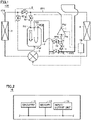
- Fig. 1 is a functional block diagram showing a configuration of a refrigeration cycle apparatus 100 according to Embodiment 1.
- refrigeration cycle apparatus 100 refrigerant is circulated.
- Refrigeration cycle apparatus 100 may be a refrigerating machine, an air conditioner, or a showcase, for example.
- the refrigeration cycle apparatus includes a compressor 1, a condenser 2 (first heat exchanger), an expansion valve 3 (decompressor), an evaporator 4 (second heat exchanger), an accumulator 5 (refrigerant container), a switch unit 6 (first switch unit), a switch unit 7 (second switch unit), and a controller 10.
- refrigerant circulates in the order of compressor 1, condenser 2, expansion valve 3, and evaporator 4.
- compressor 1 refrigeration oil (lubricating oil) for lubricating a compression mechanism is enclosed.
- Compressor 1 discharges the refrigeration oil together with refrigerant.
- Accumulator 5 stores liquid refrigerant and the refrigeration oil.
- An arrow G1 within accumulator 5 indicates the direction of gravity.
- Controller 10 controls the drive frequency of compressor 1 to control the amount of refrigerant discharged per unit time from compressor 1. Controller 10 controls the opening degree of expansion valve 3. Controller 10 controls compressor 1 and expansion valve 3 in such a manner that the degree of subcooling of refrigerant discharged from condenser 2 and the degree of superheat of refrigerant discharged from evaporator 4, for example, meet respective target values.
- Controller 10 switches the operation mode of refrigeration cycle apparatus 100.
- the operation mode includes a refrigerant discharge mode and a normal mode.
- the refrigerant discharge mode is an operation mode in which the amount of liquid refrigerant stored in accumulator 5 is reduced to increase the amount of refrigerant circulating in refrigeration cycle apparatus 100.
- the normal mode is an operation mode in which accumulator 5 is caused to store liquid refrigerant and gas refrigerant is caused to flow out from accumulator 5 into compressor 1, to thereby prevent liquid back.
- Accumulator 5 includes a port Pt1 (first port), a port Pt2 (second port), a port Pt3 (third port), and a port Pt4 (fourth port).
- Port Pt2 is formed in the bottom of accumulator 5.
- Ports Pt1, Pt3, and Pt4 are formed in the top of accumulator 5.
- the height of port Pt2 is lower than the height of each of port Pt1, port Pt3, and port Pt4. Therefore, flow of liquid refrigerant from port Pt2 can be facilitated, and flow of liquid refrigerant from ports Pt1, Pt3, and Pt4 can be suppressed.
- Switch unit 6 includes an on-off valve 61 (first valve), an on-off valve 62 (second valve), and an on-off valve 63 (third valve).
- On-off valve 61 is connected between a discharge port Ptd of compressor 1 and condenser 2.
- On-off valve 62 is connected between port Pt1 and a flow path FP1 (first flow path) from discharge port Ptd to on-off valve 61.
- On-off valve 63 is connected between port Pt2 and a flow path FP2 (second flow path) from on-off valve 61 to condenser 2.
- Switch unit 7 includes an on-off valve 71 (fourth valve), an on-off valve 72 (fifth valve), and an on-off valve 73 (sixth valve).
- On-off valve 71 is connected between evaporator 4 and a suction port Pts of compressor 1.
- On-off valve 72 is connected between port Pt3 and a flow path FP3 (third flow path) from evaporator 4 to on-off valve 71.
- On-off valve 73 is connected between port Pt4 and a flow path FP4 (fourth flow path) from on-off valve 71 to suction port Pts.
- Fig. 2 is a functional block diagram showing a configuration of controller 10 in Fig. 1 .
- controller 10 includes circuitry 11, a memory 12, and an input/output unit 13.
- Circuitry 11 may be dedicated hardware or a CPU (Central Processing Unit) that executes a program stored in memory 12.
- circuitry 11 is dedicated hardware, circuitry 11 is a single circuit, a composite circuit, a programmed processor, a parallel-programmed processor, an ASIC (Application Specific Integrated Circuit), an FPGA (Field Programmable Gate Array), or a combination thereof, for example.
- ASIC Application Specific Integrated Circuit
- FPGA Field Programmable Gate Array
- Memory 12 includes a non-volatile or volatile semiconductor memory (for example, RAM (Random Access Memory), ROM (Read Only Memory), flash memory, EPROM (Erasable Programmable Read Only Memory), or EEPROM (Electrically Erasable Programmable Read Only Memory)), and a magnetic disc, a flexible disc, an optical disc, a compact disc, a mini disc, or a DVD (Digital Versatile Disc).
- the CPU is also called central processing unit, processing unit, arithmetic unit, microprocessor, microcomputer, processor, or DSP (Digital Signal Processor).
- Input/output unit 13 receives operation from a user, and outputs a result of processing to the user.
- Input/output unit 13 includes a mouse, a keyboard, a touch panel, a display, and a speaker, for example.
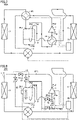
- Fig. 3 is a functional block diagram showing a flow of refrigerant when the operation mode of refrigeration cycle apparatus 100 in Fig. 1 is the refrigerant discharge mode.
- controller 10 controls switch unit 6 to direct refrigerant from compressor 1 to condenser 2 through accumulator 5.
- Controller 10 controls switch unit 7 to direct refrigerant from evaporator 4 to compressor 1 not through accumulator 5.
- Controller 10 closes on-off valve 61 and opens on-off valves 62, 63.
- Controller 10 opens on-off valve 71, and closes on-off valves 72, 73.
- Fig. 4 is a functional block diagram showing a flow of refrigerant when the operation mode of refrigeration cycle apparatus 100 in Fig. 1 is the normal mode.
- controller 10 controls switch unit 6 to direct refrigerant from compressor 1 to condenser 2 not through accumulator 5.
- Controller 10 controls switch unit 7 to direct refrigerant from evaporator 4 to compressor 1 through accumulator 5.
- Controller 10 opens on-off valve 61 and closes on-off valves 62, 63.
- Controller 10 closes on-off valve 71 and opens on-off valves 72, 73.
- liquid refrigerant may be stored in accumulator 5 as a result of cooling and resultant liquefaction of gas refrigerant. If the normal mode is started under this condition, liquid back may occur. Occurrence of the liquid back causes deterioration of the lubrication performance of refrigeration oil, which leads to an increased possibility of failure of compressor 1.
- the refrigerant discharge mode is performed when a refrigerant discharge condition (first condition) that the elapsed time from activation of compressor 1 is shorter than a reference time is satisfied, and the normal mode is performed after elapse of the reference time from the activation of compressor 1.
- first condition a refrigerant discharge condition that the elapsed time from activation of compressor 1 is shorter than a reference time
- the normal mode is performed after elapse of the reference time from the activation of compressor 1.
- liquid refrigerant in accumulator 5 is prevented from being sucked directly into compressor 1.
- the amount of liquid refrigerant stored in accumulator 5 is reduced during execution of the refrigerant discharge mode, and therefore, the amount of liquid refrigerant stored in accumulator 5, at the time when the normal mode, which is performed after elapse of the reference time, is started, can be reduced to the extent that prevents the liquid refrigerant from flowing out from accumulator 5. Consequently, liquid back in the normal mode can be suppressed.
- Fig. 5 is a flowchart showing a flow of a process performed by controller 10 in Fig. 1 .
- the process shown in Fig. 5 is followed, for each sampling time, by a main routine (not shown) that exercises overall management of refrigeration cycle apparatus 100.
- step is abbreviated simply as S.
- controller 10 determines in S101 whether or not the elapsed time from activation of compressor 1 is shorter than a reference time.
- controller 10 sets the operation mode into the refrigerant discharge mode in S102, and returns the process back to the main routine.
- controller 10 sets the operation mode into the normal mode in S103, and thereafter returns the process back to the main routine.
- the reference time in S101 may be determined appropriately through a real-machine experiment or simulation.
- Refrigeration cycle apparatus 100 is described above as the one in which each of switch units 6, 7 has three on-off valves.
- the configuration of the first switch unit and the second switch unit is not limited to the configuration of switch units 6, 7.
- the functions of each of the first switch unit and the second switch unit may also be implemented by a four-way valve.
- Fig. 6 is a functional block diagram showing a flow of refrigerant when the operation mode of a refrigeration cycle apparatus 100A according to a modification of Embodiment 1 is the refrigerant discharge mode.
- the configuration of refrigeration cycle apparatus 100A corresponds to the configuration of refrigeration cycle apparatus 100 in Fig. 1 in which switch units 6 and 7 are replaced with a four-way valve 6A (first four-way valve) and a four-way valve 7A (second four-way valve), respectively.
- switch units 6 and 7 are replaced with a four-way valve 6A (first four-way valve) and a four-way valve 7A (second four-way valve), respectively.
- These refrigeration cycle apparatuses are similar to each other in other respects, and therefore, the description thereof is not herein repeated.
- four-way valve 6A causes discharge port Ptd and port Pt1 to communicate with each other and causes port Pt2 and condenser 2 to communicate with each other.
- Four-way valve 7A causes port Pt3 and port Pt4 to communicate with each other and causes evaporator 4 and suction port Pts to communicate with each other.
- Fig. 7 is a functional block diagram showing a flow of refrigerant when the operation mode of refrigeration cycle apparatus 100A according to the modification of Embodiment 1 is the normal mode.
- four-way valve 6A causes discharge port Ptd and condenser 2 to communicate with each other and causes port Pt1 and port Pt2 to communicate with each other.
- Four-way valve 7A causes port Pt3 and evaporator 4 to communicate with each other and causes port Pt4 and suction port Pts to communicate with each other.
- the refrigeration cycle apparatuses according to Embodiment 1 and the modification thereof enable the stability to be improved.
- the above description is given of the configuration in which the refrigerant discharge mode is carried out when the refrigerant discharge condition that the elapsed time from activation of the compressor is shorter than a reference time is satisfied, in consideration of the fact that an excessive amount of liquid refrigerant may be stored in the refrigerant container when the compressor is activated.
- the refrigerant discharge condition is a condition indicative of a high possibility of occurrence of liquid back, and is not limited to the condition that the elapsed time from activation of the compressor is shorter than a reference time.
- Fig. 8 is a functional block diagram showing a configuration of a refrigeration cycle apparatus 200 according to Embodiment 2.
- the configuration of refrigeration cycle apparatus 200 corresponds to the configuration of refrigeration cycle apparatus 100 in Fig. 1 to which a liquid surface sensor 80 is added and in which controller 10 is replaced with a controller 20.
- These refrigeration cycle apparatuses are similar to each other in other respects, and therefore, the description thereof is not herein repeated.
- liquid surface sensor 80 detects height H1 of the surface of liquid stored in accumulator 5, and outputs the detected height to controller 20.
- Controller 20 switches the operation mode of refrigeration cycle apparatus 200 depending on height H1.
- Controller 20 controls compressor 1 and expansion valve 3 in a similar manner to the manner in which controller 10 in Fig. 1 controls them.
- Controller 20 controls switch units 6, 7 in a similar manner to the manner in which controller 10 controls them, in each of the refrigerant discharge mode and the normal mode.
- Fig. 9 is a flowchart showing a flow of a process of switching the operation mode that is performed by controller 20 in Fig. 8 .
- the process shown in Fig. 9 is followed, for each sampling time, by a main routine (not shown) that exercises overall management of refrigeration cycle apparatus 200.
- controller 20 determines, in S201, whether or not a condition (first condition) that height H1 is higher than reference height Hth1 (first reference height) is satisfied.
- first condition a condition that height H1 is higher than reference height Hth1 (first reference height) is satisfied.
- controller 20 sets the operation mode into the refrigerant discharge mode in S202, and returns the process back to the main routine.
- height H1 is lower than or equal to reference height Hth1 (NO in S201)
- controller 20 sets the operation mode into the normal mode in S203, and returns the process back to the main routine.
- Reference height Hth1 may be determined appropriately through a real-machine experiment or simulation.
- Fig. 10 is a functional block diagram showing a configuration of a refrigeration cycle apparatus 200A according to a modification of Embodiment 2.
- the configuration of refrigeration cycle apparatus 200A corresponds to the configuration of the apparatus shown in Fig. 8 in which liquid surface sensor 80 and controller 20 are replaced with a density sensor 81 and a controller 20A, respectively.
- These refrigeration cycle apparatuses are similar to each other in other respects, and therefore, the description thereof is not herein repeated.
- density sensor 81 outputs, to controller 20A, density D1 of refrigeration oil in liquid stored in accumulator 5. Controller 20A switches the operation mode of refrigeration cycle apparatus 200A depending on density D1.
- Fig. 11 is a flowchart showing a flow of a process of switching the operation mode that is performed by controller 20A in Fig. 10 .
- the process shown in Fig. 11 is followed, for each sampling time, by a main routine (not shown) that exercises overall management of refrigeration cycle apparatus 200A.
- controller 20A determines, in S211, whether or not a condition (first condition) that density D1 is smaller than reference density Dth1 is satisfied.
- first condition a condition that density D1 is smaller than reference density Dth1 is satisfied.
- controller 20A sets the operation mode into the refrigerant discharge mode in S212, and returns the process back to the main routine.
- density D1 is larger than or equal to reference density Dth1 (NO in S211)
- controller 20A sets the operation mode into the normal mode in S213, and returns the process back to the main routine.
- Reference density Dth1 may be determined appropriately through a real-machine experiment or simulation.
- the normal mode is performed based on the fact that the amount of liquid refrigerant stored in accumulator 5 is relatively small when density D1 is large, even if the height of the liquid surface in accumulator 5 is relatively high. Consequently, liquid back can be suppressed and deficiency of refrigeration oil in compressor 1 can be avoided, and therefore, the reliability of compressor 1 can be improved.
- the refrigerant discharge mode may also be performed, as in Embodiment 1, when the elapsed time from activation of compressor 1 is shorter than a reference time.
- the refrigerant discharge condition may include more than one of the conditions in S101 of Fig. 5 , S201 of Fig. 9 , and S211 of Fig. 11 , or include an additional condition(s).
- the refrigeration cycle apparatuses according to Embodiment 2 and the modification thereof enable the stability to be improved.
- Fig. 12 is a functional block diagram showing a configuration of a refrigeration cycle apparatus 300 according to Embodiment 3 together with a flow of refrigerant in the oil retrieval mode.
- the configuration of refrigeration cycle apparatus 300 corresponds to the configuration of refrigeration cycle apparatus 100 in Fig. 1 in which controller 10 is replaced with a controller 30. These apparatuses are similar to each other in other respects, and therefore, the description thereof is not herein repeated.
- Controller 30 performs the refrigerant discharge mode when the refrigerant discharge condition is satisfied.
- Controller 30 performs the oil retrieval mode when the refrigerant discharge condition is not satisfied and an oil retrieval condition (second condition) meaning that the amount of refrigeration oil stored in compressor 1 is excessive is satisfied.
- Controller 30 performs the normal mode when the refrigerant discharge condition is not satisfied and the oil retrieval condition is not satisfied. Controller 30 controls switch units 6, 7 in a similar manner to the manner in which they are controlled in Embodiments 1 and 2, in each of the refrigerant discharge mode and the normal mode.
- controller 30 opens on-off valves 61 and 62 and closes on-off valve 63 in the oil retrieval mode. Controller 30 opens on-off valves 71 and 73 and closes on-off valve 72. A part of refrigerant discharged from compressor 1 flows toward condenser 2 not through accumulator 5, and the remainder of the refrigerant is sucked into compressor 1 through accumulator 5. Accumulator 5 also stores refrigeration oil discharged together with refrigerant from compressor 1. The amount of refrigeration oil circulating in refrigeration cycle apparatus 300 can be reduced and the amount of refrigeration oil stored in compressor 1 can be reduced to be closer to an appropriate amount, and therefore, deterioration of the performance of refrigeration cycle apparatus 300 can be suppressed.
- Fig. 13 is a flowchart showing a flow of a process of switching the operation mode that is performed by controller 30 in Fig. 12 .
- the process shown in Fig. 13 is followed, for each sampling time, by a main routine (not shown) that exercises overall management of refrigeration cycle apparatus 300.
- controller 30 determines in S301 whether or not the refrigerant discharge condition is satisfied.
- the refrigerant discharge condition may include more than one of the conditions in S101 of Fig. 5 , S201 of Fig. 9 , and S211 of Fig. 11 , or include an additional condition(s).
- controller 30 sets the operation mode into the refrigerant discharge mode in S302, and returns the process back to the main routine.
- controller 30 determines, in S303, whether or not the oil retrieval condition is satisfied.
- the oil retrieval condition may be a condition that the amount of change per sampling time (unit time) of the drive frequency of compressor 1 is less than a reference amount, for example. The reference amount may be determine appropriately through a real-machine experiment or simulation.
- controller 30 sets the operation mode into the oil retrieval mode in S304, and returns the process back to the main routine.
- controller 30 sets the operation mode into the normal mode in S305, and returns the process back to the main routine.
- the oil retrieval condition is not limited to the condition that the amount of change, per sampling time, of the drive frequency of compressor 1 is less than a reference amount.
- the oil retrieval condition may for example be a condition that the temperature of refrigerant discharged from compressor 1 (discharge temperature) is higher than a reference temperature, a condition that the height of the surface of liquid stored in compressor 1 is higher than a reference height (second reference height), a condition that the density of refrigeration oil in liquid stored in compressor is larger than a reference density (second reference density), or a condition that the height of the surface of liquid stored in accumulator 5 is lower than a reference height (third reference height).
- the oil retrieval condition may include more than one of these conditions, or include an additional condition(s).
- Fig. 14 is a functional block diagram showing a configuration of a refrigeration cycle apparatus 300A according to Modification 1 of Embodiment 3, together with a flow of refrigerant in the oil retrieval mode.
- the configuration of refrigeration cycle apparatus 300A corresponds to the configuration of refrigeration cycle apparatus 300 in Fig. 12 to which a temperature sensor 90 is added and in which controller 30 is replaced with a controller 30A.
- temperature sensor 90 outputs discharge temperature Ts to controller 30A.
- the oil retrieval condition for refrigeration cycle apparatus 300A includes a condition that discharge temperature Ts is higher than reference temperature Tth. Reference temperature Tth may be determined appropriately through a real-machine experiment or simulation.
- Fig. 15 is a functional block diagram showing a configuration of a refrigeration cycle apparatus 300B according to Modification 2 of Embodiment 3, together with a flow of refrigerant in the oil retrieval mode.
- the configuration of refrigeration cycle apparatus 300B corresponds to the configuration of refrigeration cycle apparatus 300 in Fig. 12 to which a liquid surface sensor 91 is added and in which controller 30 is replaced with a controller 30B.
- These refrigeration cycle apparatuses are similar to each other in other respects, and therefore, the description thereof is not herein repeated.
- liquid surface sensor 91 outputs, to controller 30B, height H2 of the surface of liquid stored in compressor 1.
- the oil retrieval condition for refrigeration cycle apparatus 300B includes a condition that height H2 is higher than reference height Hth2. Reference height Hth2 may be determined appropriately through a real-machine experiment or simulation.
- Fig. 16 is a functional block diagram showing a configuration of a refrigeration cycle apparatus 300C according to Modification 3 of Embodiment 3, together with a flow of refrigerant in the oil retrieval mode.
- the configuration of refrigeration cycle apparatus 300C corresponds to the configuration of refrigeration cycle apparatus 300 in Fig. 12 to which a density sensor 92 is added and in which controller 30 is replaced with a controller 30C.
- density sensor 92 outputs, to controller 30C, density D2 of refrigeration oil in liquid stored in compressor 1.
- the oil retrieval condition for refrigeration cycle apparatus 300C includes a condition that density D2 is larger than reference density Dth2. Reference density Dth2 may be determined appropriately through a real-machine experiment or simulation.
- Fig. 17 is a functional block diagram showing a configuration of a refrigeration cycle apparatus 300D according to Modification 4 of Embodiment 3, together with a flow of refrigerant in the oil retrieval mode.
- the configuration of refrigeration cycle apparatus 300D corresponds to the configuration of refrigeration cycle apparatus 300 in Fig. 12 to which a liquid surface sensor 93 is added and in which controller 30 is replaced with a controller 30D.
- liquid surface sensor 93 outputs, to controller 30D, height H3 of the surface of liquid stored in accumulator 5.
- the oil retrieval condition for refrigeration cycle apparatus 300D includes a condition that height H3 is lower than reference height Hth3. Reference height Hth3 may be determined appropriately through a real-machine experiment or simulation.
- the refrigeration cycle apparatuses according to Embodiment 3 and Modifications 1 to 4 enable the stability to be improved.
Landscapes
- Engineering & Computer Science (AREA)
- Physics & Mathematics (AREA)
- Mechanical Engineering (AREA)
- Thermal Sciences (AREA)
- General Engineering & Computer Science (AREA)
- Chemical & Material Sciences (AREA)
- Analytical Chemistry (AREA)
- Power Engineering (AREA)
- Fluid Mechanics (AREA)
- Compressor (AREA)
Abstract
Description
- The present disclosure relates to a refrigeration cycle apparatus having a function of preventing refrigerant in liquid state (liquid refrigerant) from being sucked into a compressor.
- A conventional refrigeration cycle apparatus having a function of preventing liquid refrigerant from being sucked into a compressor (liquid back) has been known. For example,
Japanese Patent Laying-Open No. 2010-19439 - PTL 1:
Japanese Patent Laying-Open No. 2010-19439 - Depending on the time for which the refrigeration cycle apparatus is stopped, a relatively large amount of liquid refrigerant may be stored in the refrigerant container as a result of cooling and resultant liquefaction of the gas refrigerant. If the compressor is activated under this condition, liquid back may occur. Occurrence of the liquid back causes deterioration of the lubrication performance of lubricating oil stored in the compressor, which leads to an increased possibility of failure of the compressor. Moreover, depending on the amount of the lubricating oil stored in the compressor, the performance of the compressor may be deteriorated. For the refrigeration cycle apparatus disclosed in
PTL 1, however, no consideration is given to reduction of the amount of liquid refrigerant in the refrigerant container upon activation of the compressor, and no consideration is given to adjustment of the amount of the lubricating oil during operation of the compressor. - The present disclosure is made to solve the problems as described above, and an object of the present disclosure is to improve the stability of the refrigeration cycle apparatus.
- In a refrigeration cycle apparatus according to the present disclosure, refrigerant circulates in order of a compressor, a first heat exchanger, a decompressor, and a second heat exchanger. The refrigeration cycle apparatus has a refrigerant container, a first switch unit, a second switch unit, and a controller. The refrigerant container is configured to store the refrigerant in liquid state. The controller is configured to control the first switch unit and the second switch unit. When a first condition meaning that an amount of the refrigerant in liquid state stored in the refrigerant container is excessive is satisfied, the controller is configured to control the first switch unit to guide the refrigerant from the compressor to the first heat exchanger through the refrigerant container and control the second switch unit to guide the refrigerant from the second heat exchanger to the compressor not through the refrigerant container. When the first condition is not satisfied, the controller is configured to control the first switch unit to guide the refrigerant from the compressor to the first heat exchanger not through the refrigerant container and control the second switch unit to guide the refrigerant from the refrigerant container to the compressor.
- In the refrigeration cycle apparatus according to the present disclosure, when the first condition meaning that the amount of refrigerant in liquid state stored in the refrigerant container is excessive is satisfied, refrigerant is guided from the compressor to the first heat exchanger through the refrigerant container and refrigerant is guided from the second heat exchanger to the compressor not through the refrigerant container and, when the first condition is not satisfied, refrigerant is guided from the compressor to the first heat exchanger not through the refrigerant container and refrigerant is guided from the refrigerant container to the compressor. Accordingly, the stability of the refrigeration cycle apparatus can be improved.
-
-
Fig. 1 is a functional block diagram showing a configuration of a refrigeration cycle apparatus according toEmbodiment 1. -
Fig. 2 is a functional block diagram showing a configuration of a controller inFig. 1 . -
Fig. 3 is a functional block diagram showing a flow of refrigerant when the operation mode of the refrigeration cycle apparatus inFig. 1 is a refrigerant discharge mode. -
Fig. 4 is a functional block diagram showing a flow of refrigerant when the operation mode of the refrigeration cycle apparatus inFig. 1 is a normal mode. -
Fig. 5 is a flowchart showing a flow of a process performed by the controller inFig. 1 . -
Fig. 6 is a functional block diagram showing a flow of refrigerant when the operation mode of a refrigeration cycle apparatus according to a modification ofEmbodiment 1 is the refrigerant discharge mode. -
Fig. 7 is a functional block diagram showing a flow of refrigerant when the operation mode of the refrigeration cycle apparatus according to the modification ofEmbodiment 1 is the normal mode. -
Fig. 8 is a functional block diagram showing a configuration of a refrigeration cycle apparatus according toEmbodiment 2. -
Fig. 9 is a flowchart showing a flow of a process of switching the operation mode performed by a controller inFig. 8 . -
Fig. 10 is a functional block diagram showing a configuration of a refrigeration cycle apparatus according to a modification ofEmbodiment 2. -
Fig. 11 is a flowchart showing a flow of a process of switching the operation mode performed by a controller inFig. 10 . -
Fig. 12 is a functional block diagram showing a configuration of a refrigeration cycle apparatus according toEmbodiment 3, together with a flow of refrigerant in an oil retrieval mode. -
Fig. 13 is a flowchart showing a flow of a process of switching the operation mode performed by a controller inFig. 12 . -
Fig. 14 is a functional block diagram showing a configuration of a refrigeration cycle apparatus according toModification 1 ofEmbodiment 3, together with a flow of refrigerant in the oil retrieval mode. -
Fig. 15 is a functional block diagram showing a configuration of a refrigeration cycle apparatus according toModification 2 ofEmbodiment 3, together with a flow of refrigerant in the oil retrieval mode. -
Fig. 16 is a functional block diagram showing a configuration of a refrigeration cycle apparatus according toModification 3 ofEmbodiment 3, together with a flow of refrigerant in the oil retrieval mode. -
Fig. 17 is a functional block diagram showing a configuration of a refrigeration cycle apparatus according toModification 4 ofEmbodiment 3, together with a flow of refrigerant in the oil retrieval mode. - Embodiments of the present disclosure are hereinafter described in detail with reference to the drawings. In the drawings, the same or corresponding parts are denoted by the same reference characters, and a description thereof is not herein repeated in principle.
-
Fig. 1 is a functional block diagram showing a configuration of arefrigeration cycle apparatus 100 according toEmbodiment 1. Inrefrigeration cycle apparatus 100, refrigerant is circulated.Refrigeration cycle apparatus 100 may be a refrigerating machine, an air conditioner, or a showcase, for example. - As shown in
Fig. 1 , the refrigeration cycle apparatus includes acompressor 1, a condenser 2 (first heat exchanger), an expansion valve 3 (decompressor), an evaporator 4 (second heat exchanger), an accumulator 5 (refrigerant container), a switch unit 6 (first switch unit), a switch unit 7 (second switch unit), and acontroller 10. Inrefrigeration cycle apparatus 100, refrigerant circulates in the order ofcompressor 1,condenser 2,expansion valve 3, andevaporator 4. Incompressor 1, refrigeration oil (lubricating oil) for lubricating a compression mechanism is enclosed.Compressor 1 discharges the refrigeration oil together with refrigerant. Accumulator 5 stores liquid refrigerant and the refrigeration oil. An arrow G1 withinaccumulator 5 indicates the direction of gravity. -
Controller 10 controls the drive frequency ofcompressor 1 to control the amount of refrigerant discharged per unit time fromcompressor 1.Controller 10 controls the opening degree ofexpansion valve 3.Controller 10 controlscompressor 1 andexpansion valve 3 in such a manner that the degree of subcooling of refrigerant discharged fromcondenser 2 and the degree of superheat of refrigerant discharged fromevaporator 4, for example, meet respective target values. -
Controller 10 switches the operation mode ofrefrigeration cycle apparatus 100. The operation mode includes a refrigerant discharge mode and a normal mode. The refrigerant discharge mode is an operation mode in which the amount of liquid refrigerant stored inaccumulator 5 is reduced to increase the amount of refrigerant circulating inrefrigeration cycle apparatus 100. The normal mode is an operation mode in whichaccumulator 5 is caused to store liquid refrigerant and gas refrigerant is caused to flow out fromaccumulator 5 intocompressor 1, to thereby prevent liquid back. -
Accumulator 5 includes a port Pt1 (first port), a port Pt2 (second port), a port Pt3 (third port), and a port Pt4 (fourth port). Port Pt2 is formed in the bottom ofaccumulator 5. Ports Pt1, Pt3, and Pt4 are formed in the top ofaccumulator 5. The height of port Pt2 is lower than the height of each of port Pt1, port Pt3, and port Pt4. Therefore, flow of liquid refrigerant from port Pt2 can be facilitated, and flow of liquid refrigerant from ports Pt1, Pt3, and Pt4 can be suppressed. -
Switch unit 6 includes an on-off valve 61 (first valve), an on-off valve 62 (second valve), and an on-off valve 63 (third valve). On-offvalve 61 is connected between a discharge port Ptd ofcompressor 1 andcondenser 2. On-offvalve 62 is connected between port Pt1 and a flow path FP1 (first flow path) from discharge port Ptd to on-offvalve 61. On-offvalve 63 is connected between port Pt2 and a flow path FP2 (second flow path) from on-offvalve 61 tocondenser 2. -
Switch unit 7 includes an on-off valve 71 (fourth valve), an on-off valve 72 (fifth valve), and an on-off valve 73 (sixth valve). On-offvalve 71 is connected betweenevaporator 4 and a suction port Pts ofcompressor 1. On-offvalve 72 is connected between port Pt3 and a flow path FP3 (third flow path) fromevaporator 4 to on-offvalve 71. On-offvalve 73 is connected between port Pt4 and a flow path FP4 (fourth flow path) from on-offvalve 71 to suction port Pts. -
Fig. 2 is a functional block diagram showing a configuration ofcontroller 10 inFig. 1 . As shown inFig. 2 ,controller 10 includescircuitry 11, amemory 12, and an input/output unit 13.Circuitry 11 may be dedicated hardware or a CPU (Central Processing Unit) that executes a program stored inmemory 12. Whencircuitry 11 is dedicated hardware,circuitry 11 is a single circuit, a composite circuit, a programmed processor, a parallel-programmed processor, an ASIC (Application Specific Integrated Circuit), an FPGA (Field Programmable Gate Array), or a combination thereof, for example. Whencircuitry 11 is a CPU, the functions ofcontroller 10 are implemented by software, firmware, or a combination of software and firmware. The software or firmware is written as a program, and stored inmemory 12.Circuitry 11 reads and executes a program stored inmemory 12.Memory 12 includes a non-volatile or volatile semiconductor memory (for example, RAM (Random Access Memory), ROM (Read Only Memory), flash memory, EPROM (Erasable Programmable Read Only Memory), or EEPROM (Electrically Erasable Programmable Read Only Memory)), and a magnetic disc, a flexible disc, an optical disc, a compact disc, a mini disc, or a DVD (Digital Versatile Disc). The CPU is also called central processing unit, processing unit, arithmetic unit, microprocessor, microcomputer, processor, or DSP (Digital Signal Processor). - Input/
output unit 13 receives operation from a user, and outputs a result of processing to the user. Input/output unit 13 includes a mouse, a keyboard, a touch panel, a display, and a speaker, for example. -
Fig. 3 is a functional block diagram showing a flow of refrigerant when the operation mode ofrefrigeration cycle apparatus 100 inFig. 1 is the refrigerant discharge mode. As shown inFig. 3 ,controller 10 controls switchunit 6 to direct refrigerant fromcompressor 1 tocondenser 2 throughaccumulator 5.Controller 10 controls switchunit 7 to direct refrigerant fromevaporator 4 tocompressor 1 not throughaccumulator 5.Controller 10 closes on-offvalve 61 and opens on-offvalves Controller 10 opens on-offvalve 71, and closes on-offvalves -
Fig. 4 is a functional block diagram showing a flow of refrigerant when the operation mode ofrefrigeration cycle apparatus 100 inFig. 1 is the normal mode. As shown inFig. 4 ,controller 10 controls switchunit 6 to direct refrigerant fromcompressor 1 tocondenser 2 not throughaccumulator 5.Controller 10 controls switchunit 7 to direct refrigerant fromevaporator 4 tocompressor 1 throughaccumulator 5.Controller 10 opens on-offvalve 61 and closes on-offvalves Controller 10 closes on-offvalve 71 and opens on-offvalves - Depending on the time for which
refrigeration cycle apparatus 100 is stopped, a relatively large amount of liquid refrigerant may be stored inaccumulator 5 as a result of cooling and resultant liquefaction of gas refrigerant. If the normal mode is started under this condition, liquid back may occur. Occurrence of the liquid back causes deterioration of the lubrication performance of refrigeration oil, which leads to an increased possibility of failure ofcompressor 1. - In
refrigeration cycle apparatus 100, therefore, the refrigerant discharge mode is performed when a refrigerant discharge condition (first condition) that the elapsed time from activation ofcompressor 1 is shorter than a reference time is satisfied, and the normal mode is performed after elapse of the reference time from the activation ofcompressor 1. During the reference time from activation ofcompressor 1, liquid refrigerant inaccumulator 5 is prevented from being sucked directly intocompressor 1. The amount of liquid refrigerant stored inaccumulator 5 is reduced during execution of the refrigerant discharge mode, and therefore, the amount of liquid refrigerant stored inaccumulator 5, at the time when the normal mode, which is performed after elapse of the reference time, is started, can be reduced to the extent that prevents the liquid refrigerant from flowing out fromaccumulator 5. Consequently, liquid back in the normal mode can be suppressed. -
Fig. 5 is a flowchart showing a flow of a process performed bycontroller 10 inFig. 1 . The process shown inFig. 5 is followed, for each sampling time, by a main routine (not shown) that exercises overall management ofrefrigeration cycle apparatus 100. In the following, step is abbreviated simply as S. - As shown in
Fig. 5 ,controller 10 determines in S101 whether or not the elapsed time from activation ofcompressor 1 is shorter than a reference time. When the elapsed time from activation ofcompressor 1 is shorter than the reference time (YES in S101),controller 10 sets the operation mode into the refrigerant discharge mode in S102, and returns the process back to the main routine. When the elapsed time from activation ofcompressor 1 is longer than or equal to the reference time (NO in S101),controller 10 sets the operation mode into the normal mode in S103, and thereafter returns the process back to the main routine. The reference time in S101 may be determined appropriately through a real-machine experiment or simulation. -
Refrigeration cycle apparatus 100 is described above as the one in which each ofswitch units switch units -
Fig. 6 is a functional block diagram showing a flow of refrigerant when the operation mode of a refrigeration cycle apparatus 100A according to a modification ofEmbodiment 1 is the refrigerant discharge mode. The configuration of refrigeration cycle apparatus 100A corresponds to the configuration ofrefrigeration cycle apparatus 100 inFig. 1 in which switchunits way valve 6A (first four-way valve) and a four-way valve 7A (second four-way valve), respectively. These refrigeration cycle apparatuses are similar to each other in other respects, and therefore, the description thereof is not herein repeated. - As shown in
Fig. 6 , four-way valve 6A causes discharge port Ptd and port Pt1 to communicate with each other and causes port Pt2 andcondenser 2 to communicate with each other. Four-way valve 7A causes port Pt3 and port Pt4 to communicate with each other and causesevaporator 4 and suction port Pts to communicate with each other. -
Fig. 7 is a functional block diagram showing a flow of refrigerant when the operation mode of refrigeration cycle apparatus 100A according to the modification ofEmbodiment 1 is the normal mode. As shown inFig. 7 , four-way valve 6A causes discharge port Ptd andcondenser 2 to communicate with each other and causes port Pt1 and port Pt2 to communicate with each other. Four-way valve 7A causes port Pt3 andevaporator 4 to communicate with each other and causes port Pt4 and suction port Pts to communicate with each other. - Accordingly, the refrigeration cycle apparatuses according to
Embodiment 1 and the modification thereof enable the stability to be improved. - In connection with
Embodiment 1, the above description is given of the configuration in which the refrigerant discharge mode is carried out when the refrigerant discharge condition that the elapsed time from activation of the compressor is shorter than a reference time is satisfied, in consideration of the fact that an excessive amount of liquid refrigerant may be stored in the refrigerant container when the compressor is activated. The refrigerant discharge condition is a condition indicative of a high possibility of occurrence of liquid back, and is not limited to the condition that the elapsed time from activation of the compressor is shorter than a reference time. In connection withEmbodiment 2, a description is given below of a configuration in which the operation mode is switched between the refrigerant discharge mode and the normal mode, in consideration of the height of the surface of liquid stored in the refrigerant container, or the density of lubricating oil for the compressor in liquid stored in the refrigerant container. -
Fig. 8 is a functional block diagram showing a configuration of a refrigeration cycle apparatus 200 according toEmbodiment 2. The configuration of refrigeration cycle apparatus 200 corresponds to the configuration ofrefrigeration cycle apparatus 100 inFig. 1 to which aliquid surface sensor 80 is added and in whichcontroller 10 is replaced with acontroller 20. These refrigeration cycle apparatuses are similar to each other in other respects, and therefore, the description thereof is not herein repeated. - As shown in
Fig. 8 ,liquid surface sensor 80 detects height H1 of the surface of liquid stored inaccumulator 5, and outputs the detected height tocontroller 20.Controller 20 switches the operation mode of refrigeration cycle apparatus 200 depending on height H1.Controller 20controls compressor 1 andexpansion valve 3 in a similar manner to the manner in whichcontroller 10 inFig. 1 controls them.Controller 20 controls switchunits controller 10 controls them, in each of the refrigerant discharge mode and the normal mode. -
Fig. 9 is a flowchart showing a flow of a process of switching the operation mode that is performed bycontroller 20 inFig. 8 . The process shown inFig. 9 is followed, for each sampling time, by a main routine (not shown) that exercises overall management of refrigeration cycle apparatus 200. - As shown in
Fig. 9 ,controller 20 determines, in S201, whether or not a condition (first condition) that height H1 is higher than reference height Hth1 (first reference height) is satisfied. When height H1 is higher than reference height Hth1 (YES in S201),controller 20 sets the operation mode into the refrigerant discharge mode in S202, and returns the process back to the main routine. When height H1 is lower than or equal to reference height Hth1 (NO in S201),controller 20 sets the operation mode into the normal mode in S203, and returns the process back to the main routine. Reference height Hth1 may be determined appropriately through a real-machine experiment or simulation. -
Fig. 10 is a functional block diagram showing a configuration of a refrigeration cycle apparatus 200A according to a modification ofEmbodiment 2. The configuration of refrigeration cycle apparatus 200A corresponds to the configuration of the apparatus shown inFig. 8 in whichliquid surface sensor 80 andcontroller 20 are replaced with a density sensor 81 and acontroller 20A, respectively. These refrigeration cycle apparatuses are similar to each other in other respects, and therefore, the description thereof is not herein repeated. - As shown in
Fig. 10 , density sensor 81 outputs, tocontroller 20A, density D1 of refrigeration oil in liquid stored inaccumulator 5.Controller 20A switches the operation mode of refrigeration cycle apparatus 200A depending on density D1. -
Fig. 11 is a flowchart showing a flow of a process of switching the operation mode that is performed bycontroller 20A inFig. 10 . The process shown inFig. 11 is followed, for each sampling time, by a main routine (not shown) that exercises overall management of refrigeration cycle apparatus 200A. - As shown in
Fig. 11 ,controller 20A determines, in S211, whether or not a condition (first condition) that density D1 is smaller than reference density Dth1 is satisfied. When density D1 is smaller than reference density Dth1 (first reference density) (YES in S211),controller 20A sets the operation mode into the refrigerant discharge mode in S212, and returns the process back to the main routine. When density D1 is larger than or equal to reference density Dth1 (NO in S211),controller 20A sets the operation mode into the normal mode in S213, and returns the process back to the main routine. Reference density Dth1 may be determined appropriately through a real-machine experiment or simulation. - In refrigeration cycle apparatus 200A, the normal mode is performed based on the fact that the amount of liquid refrigerant stored in
accumulator 5 is relatively small when density D1 is large, even if the height of the liquid surface inaccumulator 5 is relatively high. Consequently, liquid back can be suppressed and deficiency of refrigeration oil incompressor 1 can be avoided, and therefore, the reliability ofcompressor 1 can be improved. - In refrigeration cycle apparatuses 200, 200A, the refrigerant discharge mode may also be performed, as in
Embodiment 1, when the elapsed time from activation ofcompressor 1 is shorter than a reference time. The refrigerant discharge condition may include more than one of the conditions in S101 ofFig. 5 , S201 ofFig. 9 , and S211 ofFig. 11 , or include an additional condition(s). - Accordingly, the refrigeration cycle apparatuses according to
Embodiment 2 and the modification thereof enable the stability to be improved. - In connection with
Embodiment 3, a description is given below of a configuration in which the operation mode is switched, when the refrigerant discharge condition is not satisfied, between the normal mode and an oil retrieval mode of retrieving lubricating oil stored in the refrigerant container into the compressor, in order to appropriately maintain the amount of lubricating oil stored in the compressor. -
Fig. 12 is a functional block diagram showing a configuration of arefrigeration cycle apparatus 300 according toEmbodiment 3 together with a flow of refrigerant in the oil retrieval mode. The configuration ofrefrigeration cycle apparatus 300 corresponds to the configuration ofrefrigeration cycle apparatus 100 inFig. 1 in whichcontroller 10 is replaced with acontroller 30. These apparatuses are similar to each other in other respects, and therefore, the description thereof is not herein repeated.Controller 30 performs the refrigerant discharge mode when the refrigerant discharge condition is satisfied.Controller 30 performs the oil retrieval mode when the refrigerant discharge condition is not satisfied and an oil retrieval condition (second condition) meaning that the amount of refrigeration oil stored incompressor 1 is excessive is satisfied.Controller 30 performs the normal mode when the refrigerant discharge condition is not satisfied and the oil retrieval condition is not satisfied.Controller 30 controls switchunits Embodiments - As shown in
Fig. 12 ,controller 30 opens on-offvalves valve 63 in the oil retrieval mode.Controller 30 opens on-offvalves valve 72. A part of refrigerant discharged fromcompressor 1 flows towardcondenser 2 not throughaccumulator 5, and the remainder of the refrigerant is sucked intocompressor 1 throughaccumulator 5.Accumulator 5 also stores refrigeration oil discharged together with refrigerant fromcompressor 1. The amount of refrigeration oil circulating inrefrigeration cycle apparatus 300 can be reduced and the amount of refrigeration oil stored incompressor 1 can be reduced to be closer to an appropriate amount, and therefore, deterioration of the performance ofrefrigeration cycle apparatus 300 can be suppressed. -
Fig. 13 is a flowchart showing a flow of a process of switching the operation mode that is performed bycontroller 30 inFig. 12 . The process shown inFig. 13 is followed, for each sampling time, by a main routine (not shown) that exercises overall management ofrefrigeration cycle apparatus 300. - As shown in
Fig. 13 ,controller 30 determines in S301 whether or not the refrigerant discharge condition is satisfied. The refrigerant discharge condition may include more than one of the conditions in S101 ofFig. 5 , S201 ofFig. 9 , and S211 ofFig. 11 , or include an additional condition(s). When the refrigerant discharge condition is satisfied (YES in S301),controller 30 sets the operation mode into the refrigerant discharge mode in S302, and returns the process back to the main routine. When the refrigerant discharge condition is not satisfied (NO in S301),controller 30 determines, in S303, whether or not the oil retrieval condition is satisfied. The oil retrieval condition may be a condition that the amount of change per sampling time (unit time) of the drive frequency ofcompressor 1 is less than a reference amount, for example. The reference amount may be determine appropriately through a real-machine experiment or simulation. - When the oil retrieval condition is satisfied (YES in S303),
controller 30 sets the operation mode into the oil retrieval mode in S304, and returns the process back to the main routine. When the oil retrieval condition is not satisfied (NO in S303),controller 30 sets the operation mode into the normal mode in S305, and returns the process back to the main routine. - The oil retrieval condition is not limited to the condition that the amount of change, per sampling time, of the drive frequency of
compressor 1 is less than a reference amount. The oil retrieval condition may for example be a condition that the temperature of refrigerant discharged from compressor 1 (discharge temperature) is higher than a reference temperature, a condition that the height of the surface of liquid stored incompressor 1 is higher than a reference height (second reference height), a condition that the density of refrigeration oil in liquid stored in compressor is larger than a reference density (second reference density), or a condition that the height of the surface of liquid stored inaccumulator 5 is lower than a reference height (third reference height). The oil retrieval condition may include more than one of these conditions, or include an additional condition(s). -
Fig. 14 is a functional block diagram showing a configuration of a refrigeration cycle apparatus 300A according toModification 1 ofEmbodiment 3, together with a flow of refrigerant in the oil retrieval mode. The configuration of refrigeration cycle apparatus 300A corresponds to the configuration ofrefrigeration cycle apparatus 300 inFig. 12 to which a temperature sensor 90 is added and in whichcontroller 30 is replaced with acontroller 30A. These refrigeration cycle apparatuses are similar to each other in other respects, and therefore, the description thereof is not herein repeated. As shown inFig. 14 , temperature sensor 90 outputs discharge temperature Ts tocontroller 30A. The oil retrieval condition for refrigeration cycle apparatus 300A includes a condition that discharge temperature Ts is higher than reference temperature Tth. Reference temperature Tth may be determined appropriately through a real-machine experiment or simulation. -
Fig. 15 is a functional block diagram showing a configuration of a refrigeration cycle apparatus 300B according toModification 2 ofEmbodiment 3, together with a flow of refrigerant in the oil retrieval mode. The configuration of refrigeration cycle apparatus 300B corresponds to the configuration ofrefrigeration cycle apparatus 300 inFig. 12 to which aliquid surface sensor 91 is added and in whichcontroller 30 is replaced with acontroller 30B. These refrigeration cycle apparatuses are similar to each other in other respects, and therefore, the description thereof is not herein repeated. As shown inFig. 15 ,liquid surface sensor 91 outputs, tocontroller 30B, height H2 of the surface of liquid stored incompressor 1. The oil retrieval condition for refrigeration cycle apparatus 300B includes a condition that height H2 is higher than reference height Hth2. Reference height Hth2 may be determined appropriately through a real-machine experiment or simulation. -
Fig. 16 is a functional block diagram showing a configuration of a refrigeration cycle apparatus 300C according toModification 3 ofEmbodiment 3, together with a flow of refrigerant in the oil retrieval mode. The configuration of refrigeration cycle apparatus 300C corresponds to the configuration ofrefrigeration cycle apparatus 300 inFig. 12 to which adensity sensor 92 is added and in whichcontroller 30 is replaced with acontroller 30C. These refrigeration cycle apparatuses are similar to each other in other respects, and therefore, the description thereof is not herein repeated. As shown inFig. 16 ,density sensor 92 outputs, tocontroller 30C, density D2 of refrigeration oil in liquid stored incompressor 1. The oil retrieval condition for refrigeration cycle apparatus 300C includes a condition that density D2 is larger than reference density Dth2. Reference density Dth2 may be determined appropriately through a real-machine experiment or simulation. -
Fig. 17 is a functional block diagram showing a configuration of a refrigeration cycle apparatus 300D according toModification 4 ofEmbodiment 3, together with a flow of refrigerant in the oil retrieval mode. The configuration of refrigeration cycle apparatus 300D corresponds to the configuration ofrefrigeration cycle apparatus 300 inFig. 12 to which aliquid surface sensor 93 is added and in whichcontroller 30 is replaced with acontroller 30D. These refrigeration cycle apparatuses are similar to each other in other respects, and therefore, the description thereof is not herein repeated. As shown inFig. 17 ,liquid surface sensor 93 outputs, tocontroller 30D, height H3 of the surface of liquid stored inaccumulator 5. The oil retrieval condition for refrigeration cycle apparatus 300D includes a condition that height H3 is lower than reference height Hth3. Reference height Hth3 may be determined appropriately through a real-machine experiment or simulation. - Accordingly, the refrigeration cycle apparatuses according to
Embodiment 3 andModifications 1 to 4 enable the stability to be improved. - The embodiments disclosed herein are also intended to be implemented in an appropriate combination within the range where they are consistent with each other.
- It should be construed that the embodiments disclosed herein are given by way of illustration in all respects, not by way of limitation. It is intended that the scope of the present disclosure is defined by claims, not by the description above, and encompasses all modifications and variations equivalent in meaning and scope to the claims.
- 1 compressor; 2 condenser; 3 expansion valve; 4 evaporator; 5 accumulator; 6, 7 switch unit; 6A, 7A four-way valve; 10, 20, 20A, 30, 30A, 30B, 30C, 30D controller; 11 circuitry; 12 memory; 13 input/output unit; 61-63, 71-73 on-off valve; 80, 91, 93 liquid surface sensor; 81, 92 density sensor; 90 temperature sensor; 100, 100A, 200, 200A, 300, 300A-300D refrigeration cycle apparatus; FP1-FP4 flow path; Pt1-Pt4 port; Ptd discharge port; Pts suction port
Claims (13)
- A refrigeration cycle apparatus in which refrigerant circulates in order of a compressor, a first heat exchanger, a decompressor, and a second heat exchanger, the refrigeration cycle apparatus comprising:a refrigerant container configured to store the refrigerant in liquid state;a first switch unit and a second switch unit; anda controller configured to control the first switch unit and the second switch unit,when a first condition is satisfied, the controller being configured to control the first switch unit to guide the refrigerant from the compressor to the first heat exchanger through the refrigerant container and to control the second switch unit to guide the refrigerant from the second heat exchanger to the compressor not through the refrigerant container, the first condition meaning that an amount of the refrigerant in liquid state stored in the refrigerant container is excessive,when the first condition is not satisfied, the controller being configured to control the first switch unit to guide the refrigerant from the compressor to the first heat exchanger not through the refrigerant container and to control the second switch unit to guide the refrigerant from the refrigerant container to the compressor.
- The refrigeration cycle apparatus according to claim 1, wherein the first condition includes a condition that an elapsed time from activation of the compressor is shorter than a reference time.
- The refrigeration cycle apparatus according to claim 1, wherein the first condition includes a condition that a height of a surface of liquid stored in the refrigerant container is higher than a first reference height.
- The refrigeration cycle apparatus according to claim 1, wherein the first condition includes a condition that a density of lubricating oil for the compressor in liquid stored in the refrigerant container is smaller than a first reference density.
- The refrigeration cycle apparatus according to any one of claims 1 to 4, whereinthe refrigerant container includes a first port, a second port, a third port, and a fourth port,the first switch unit includes a first four-way valve,the second switch unit includes a second four-way valve,when the first condition is satisfied, the controller is configured to control the first four-way valve to cause a discharge port of the compressor and the first port to communicate with each other and cause the second port and the first heat exchanger to communicate with each other, and control the second four-way valve to cause the third port and the fourth port to communicate with each other and cause the second heat exchanger and a suction port of the compressor to communicate with each other, andwhen the first condition is not satisfied, the controller is configured to control the first four-way valve to cause the discharge port and the first heat exchanger to communicate with each other and cause the first port and the second port to communicate with each other, and control the second four-way valve to cause the third port and the second heat exchanger to communicate with each other and cause the fourth port and the suction port to communicate with each other.
- The refrigeration cycle apparatus according to any one of claims 1 to 4, whereinthe refrigerant container includes a first port, a second port, a third port, and a fourth port,the first switch unit includes a first valve, a second valve, and a third valve,the first valve is connected between a discharge port of the compressor and the first heat exchanger,the second valve is connected between the first port and a first flow path from the discharge port to the first valve,the second switch unit includes a fourth valve, a fifth valve, and a sixth valve,the third valve is connected between the second port and a second flow path from the first valve to the first heat exchanger,the fourth valve is connected between the second heat exchanger and a suction port of the compressor,the fifth valve is connected between the third port and a third flow path from the second heat exchanger to the fourth valve,the sixth valve is connected between the fourth port and a fourth flow path from the fourth valve to the suction port,when the first condition is satisfied, the controller is configured to close the first valve, open the second valve and the third valve, open the fourth valve, and close the fifth valve and the sixth valve, andwhen the first condition is not satisfied, the controller is configured to open the first valve and open the sixth valve.
- The refrigeration cycle apparatus according to claim 6, whereinwhen the first condition is not satisfied and a second condition meaning that an amount of lubricating oil stored in the compressor is excessive is satisfied, the controller is configured to open the first valve and the second valve, close the third valve, open the fourth valve, close the fifth valve, and open the sixth valve, andwhen the first condition is not satisfied and the second condition is not satisfied, the controller is configured to open the first valve, close the second valve and the third valve, close the fourth valve, and open the fifth valve and the sixth valve.
- The refrigeration cycle apparatus according to claim 7, wherein the second condition includes a condition that an amount of change, per unit time, of a drive frequency of the compressor is smaller than a reference amount.
- The refrigeration cycle apparatus according to claim 7, wherein the second condition includes a condition that a temperature of the refrigerant discharged from the compressor is higher than a reference temperature.
- The refrigeration cycle apparatus according to claim 7, wherein the second condition includes a condition that a height of a surface of liquid stored in the compressor is higher than a second reference height.
- The refrigeration cycle apparatus according to claim 7, wherein the second condition includes a condition that a density of lubricating oil for the compressor in liquid stored in the compressor is larger than a second reference density.
- The refrigeration cycle apparatus according to claim 7, wherein the second condition includes a condition that a height of a surface of liquid stored in the refrigerant container is lower than a third reference height.
- The refrigeration cycle apparatus according to any one of claims 5 to 12, wherein a height of the second port is lower than a height of each of the first port, the third port, and the fourth port.
Applications Claiming Priority (1)
| Application Number | Priority Date | Filing Date | Title |
|---|---|---|---|
| PCT/JP2020/000498 WO2021140625A1 (en) | 2020-01-09 | 2020-01-09 | Refrigeration cycle device |
Publications (2)
| Publication Number | Publication Date |
|---|---|
| EP4089346A1 true EP4089346A1 (en) | 2022-11-16 |
| EP4089346A4 EP4089346A4 (en) | 2022-12-28 |
Family
ID=76787800
Family Applications (1)
| Application Number | Title | Priority Date | Filing Date |
|---|---|---|---|
| EP20912140.9A Withdrawn EP4089346A4 (en) | 2020-01-09 | 2020-01-09 | Refrigeration cycle device |
Country Status (5)
| Country | Link |
|---|---|
| US (1) | US20220390161A1 (en) |
| EP (1) | EP4089346A4 (en) |
| JP (1) | JP7325542B2 (en) |
| CN (1) | CN114902009B (en) |
| WO (1) | WO2021140625A1 (en) |
Families Citing this family (3)
| Publication number | Priority date | Publication date | Assignee | Title |
|---|---|---|---|---|
| JP7297162B1 (en) * | 2022-02-03 | 2023-06-23 | 三菱電機株式会社 | Refrigeration cycle device and control method |
| KR102532023B1 (en) * | 2022-09-29 | 2023-05-16 | 주식회사 한국마이콤 | Supercritical refrigeration system and control method of same |
| DE102023123745A1 (en) * | 2023-09-04 | 2025-03-06 | Denso Automotive Deutschland Gmbh | Thermal management system for vehicles and method for operating such a thermal management system |
Family Cites Families (17)
| Publication number | Priority date | Publication date | Assignee | Title |
|---|---|---|---|---|
| US5094086A (en) * | 1990-09-25 | 1992-03-10 | Norm Pacific Automation Corp. | Instant cooling system with refrigerant storage |
| JP2720114B2 (en) * | 1990-12-14 | 1998-02-25 | 株式会社日立製作所 | Air conditioner |
| JPH07301459A (en) * | 1994-05-09 | 1995-11-14 | Kubota Corp | Heat pump device |
| US7010927B2 (en) * | 2003-11-07 | 2006-03-14 | Carrier Corporation | Refrigerant system with controlled refrigerant charge amount |
| EP1886080A4 (en) * | 2005-06-03 | 2010-09-15 | Carrier Corp | Refrigerant charge control in a heat pump system with water heating |
| JP4884432B2 (en) | 2008-07-08 | 2012-02-29 | 三菱電機株式会社 | Refrigeration cycle apparatus and method for operating refrigeration cycle apparatus |
| CN102042724B (en) * | 2009-10-13 | 2012-07-04 | 珠海格力电器股份有限公司 | Refrigerant control component, air-conditioning refrigeration system and refrigerant circulation control method |
| CN202281429U (en) * | 2011-08-16 | 2012-06-20 | 高立铭 | Gas separation heat exchanger of sucked air gathering pipe |
| CN102338522A (en) * | 2011-09-24 | 2012-02-01 | 林勇 | Self-closing and anti-liquid impact device for air-cooled heat pump air conditioner |
| US9958190B2 (en) * | 2013-01-24 | 2018-05-01 | Advantek Consulting Engineering, Inc. | Optimizing energy efficiency ratio feedback control for direct expansion air-conditioners and heat pumps |
| JP6072178B1 (en) * | 2015-09-10 | 2017-02-01 | 三菱電機株式会社 | Refrigeration cycle equipment |
| US10830515B2 (en) * | 2015-10-21 | 2020-11-10 | Mitsubishi Electric Research Laboratories, Inc. | System and method for controlling refrigerant in vapor compression system |
| JP6644160B2 (en) | 2016-10-18 | 2020-02-12 | 三菱電機株式会社 | Refrigeration cycle device |
| KR102243376B1 (en) * | 2017-05-08 | 2021-04-22 | 엘지전자 주식회사 | Air conditioning system |
| JP6971776B2 (en) * | 2017-10-25 | 2021-11-24 | 三菱重工サーマルシステムズ株式会社 | Bleed air control device and control method |
| US10837685B2 (en) * | 2018-06-29 | 2020-11-17 | Johnson Controls Technology Company | HVAC refrigerant charging and relieving systems and methods |
| CN109579347A (en) * | 2018-12-04 | 2019-04-05 | 南京天加环境科技有限公司 | A kind of multi-line system and its control method that can be avoided compressor and return liquid |
-
2020
- 2020-01-09 EP EP20912140.9A patent/EP4089346A4/en not_active Withdrawn
- 2020-01-09 JP JP2021569674A patent/JP7325542B2/en active Active
- 2020-01-09 US US17/777,114 patent/US20220390161A1/en not_active Abandoned
- 2020-01-09 CN CN202080091574.8A patent/CN114902009B/en not_active Expired - Fee Related
- 2020-01-09 WO PCT/JP2020/000498 patent/WO2021140625A1/en not_active Ceased
Also Published As
| Publication number | Publication date |
|---|---|
| CN114902009A (en) | 2022-08-12 |
| US20220390161A1 (en) | 2022-12-08 |
| JPWO2021140625A1 (en) | 2021-07-15 |
| EP4089346A4 (en) | 2022-12-28 |
| CN114902009B (en) | 2023-07-07 |
| JP7325542B2 (en) | 2023-08-14 |
| WO2021140625A1 (en) | 2021-07-15 |
Similar Documents
| Publication | Publication Date | Title |
|---|---|---|
| EP4089346A1 (en) | Refrigeration cycle device | |
| TWI407066B (en) | Economized refrigeration system | |
| JP6793862B1 (en) | Refrigeration cycle equipment | |
| EP3287720B1 (en) | Refrigeration device | |
| EP4053470A1 (en) | Refrigeration cycle device | |
| CN108474612B (en) | Refrigerator and control method thereof | |
| EP3633278B1 (en) | Air conditioner | |
| US12092383B2 (en) | Refrigeration cycle device | |
| JP7386894B2 (en) | Refrigeration cycle equipment | |
| EP4317834A1 (en) | Refrigeration cycle device | |
| EP3546851A1 (en) | Refrigerating device | |
| EP3875869A1 (en) | Heat pump system and method for controlling the same | |
| EP4350253A1 (en) | Refrigeration cycle device | |
| EP3892940B1 (en) | Refrigeration cycle device | |
| EP4170257B1 (en) | Refrigeration cycle device | |
| JP7778242B2 (en) | air conditioning system | |
| JP7204947B2 (en) | air conditioner | |
| EP4641115A1 (en) | Air conditioner | |
| US20250369670A1 (en) | Refrigeration cycle device | |
| EP4542142A1 (en) | Heat source unit and freezing device | |
| EP4502501A1 (en) | Air conditioner | |
| US20240151442A1 (en) | Refrigeration cycle apparatus | |
| JP2020046089A (en) | Control device, temperature adjustment device and control method | |
| JP2011257040A (en) | Refrigerator and control device of electronic expansion valve for the same | |
| CN112413920A (en) | freezer |
Legal Events
| Date | Code | Title | Description |
|---|---|---|---|
| STAA | Information on the status of an ep patent application or granted ep patent |
Free format text: STATUS: THE INTERNATIONAL PUBLICATION HAS BEEN MADE |
|
| PUAI | Public reference made under article 153(3) epc to a published international application that has entered the european phase |
Free format text: ORIGINAL CODE: 0009012 |
|
| STAA | Information on the status of an ep patent application or granted ep patent |
Free format text: STATUS: REQUEST FOR EXAMINATION WAS MADE |
|
| 17P | Request for examination filed |
Effective date: 20220630 |
|
| AK | Designated contracting states |
Kind code of ref document: A1 Designated state(s): AL AT BE BG CH CY CZ DE DK EE ES FI FR GB GR HR HU IE IS IT LI LT LU LV MC MK MT NL NO PL PT RO RS SE SI SK SM TR |
|
| A4 | Supplementary search report drawn up and despatched |
Effective date: 20221125 |
|
| RIC1 | Information provided on ipc code assigned before grant |
Ipc: F25B 43/00 20060101ALI20221121BHEP Ipc: F25B 49/02 20060101ALI20221121BHEP Ipc: F25B 41/26 20210101ALI20221121BHEP Ipc: F25B 41/22 20210101ALI20221121BHEP Ipc: F25B 41/20 20210101ALI20221121BHEP Ipc: F25B 1/00 20060101ALI20221121BHEP Ipc: F25B 41/00 20210101AFI20221121BHEP |
|
| DAV | Request for validation of the european patent (deleted) | ||
| DAX | Request for extension of the european patent (deleted) | ||
| STAA | Information on the status of an ep patent application or granted ep patent |
Free format text: STATUS: THE APPLICATION HAS BEEN WITHDRAWN |
|
| 18W | Application withdrawn |
Effective date: 20240829 |