EP4089345A1 - Refrigeration cycle device and liquid heating device having the same - Google Patents
Refrigeration cycle device and liquid heating device having the same Download PDFInfo
- Publication number
- EP4089345A1 EP4089345A1 EP22171958.6A EP22171958A EP4089345A1 EP 4089345 A1 EP4089345 A1 EP 4089345A1 EP 22171958 A EP22171958 A EP 22171958A EP 4089345 A1 EP4089345 A1 EP 4089345A1
- Authority
- EP
- European Patent Office
- Prior art keywords
- refrigerant
- temperature
- pressure
- heat medium
- heat exchanger
- Prior art date
- Legal status (The legal status is an assumption and is not a legal conclusion. Google has not performed a legal analysis and makes no representation as to the accuracy of the status listed.)
- Pending
Links
Images
Classifications
-
- F—MECHANICAL ENGINEERING; LIGHTING; HEATING; WEAPONS; BLASTING
- F25—REFRIGERATION OR COOLING; COMBINED HEATING AND REFRIGERATION SYSTEMS; HEAT PUMP SYSTEMS; MANUFACTURE OR STORAGE OF ICE; LIQUEFACTION SOLIDIFICATION OF GASES
- F25B—REFRIGERATION MACHINES, PLANTS OR SYSTEMS; COMBINED HEATING AND REFRIGERATION SYSTEMS; HEAT PUMP SYSTEMS
- F25B1/00—Compression machines, plants or systems with non-reversible cycle
- F25B1/10—Compression machines, plants or systems with non-reversible cycle with multi-stage compression
-
- F—MECHANICAL ENGINEERING; LIGHTING; HEATING; WEAPONS; BLASTING
- F25—REFRIGERATION OR COOLING; COMBINED HEATING AND REFRIGERATION SYSTEMS; HEAT PUMP SYSTEMS; MANUFACTURE OR STORAGE OF ICE; LIQUEFACTION SOLIDIFICATION OF GASES
- F25B—REFRIGERATION MACHINES, PLANTS OR SYSTEMS; COMBINED HEATING AND REFRIGERATION SYSTEMS; HEAT PUMP SYSTEMS
- F25B1/00—Compression machines, plants or systems with non-reversible cycle
- F25B1/04—Compression machines, plants or systems with non-reversible cycle with compressor of rotary type
-
- F—MECHANICAL ENGINEERING; LIGHTING; HEATING; WEAPONS; BLASTING
- F25—REFRIGERATION OR COOLING; COMBINED HEATING AND REFRIGERATION SYSTEMS; HEAT PUMP SYSTEMS; MANUFACTURE OR STORAGE OF ICE; LIQUEFACTION SOLIDIFICATION OF GASES
- F25B—REFRIGERATION MACHINES, PLANTS OR SYSTEMS; COMBINED HEATING AND REFRIGERATION SYSTEMS; HEAT PUMP SYSTEMS
- F25B25/00—Machines, plants or systems, using a combination of modes of operation covered by two or more of the groups F25B1/00 - F25B23/00
- F25B25/005—Machines, plants or systems, using a combination of modes of operation covered by two or more of the groups F25B1/00 - F25B23/00 using primary and secondary systems
-
- F—MECHANICAL ENGINEERING; LIGHTING; HEATING; WEAPONS; BLASTING
- F25—REFRIGERATION OR COOLING; COMBINED HEATING AND REFRIGERATION SYSTEMS; HEAT PUMP SYSTEMS; MANUFACTURE OR STORAGE OF ICE; LIQUEFACTION SOLIDIFICATION OF GASES
- F25B—REFRIGERATION MACHINES, PLANTS OR SYSTEMS; COMBINED HEATING AND REFRIGERATION SYSTEMS; HEAT PUMP SYSTEMS
- F25B40/00—Subcoolers, desuperheaters or superheaters
-
- F—MECHANICAL ENGINEERING; LIGHTING; HEATING; WEAPONS; BLASTING
- F25—REFRIGERATION OR COOLING; COMBINED HEATING AND REFRIGERATION SYSTEMS; HEAT PUMP SYSTEMS; MANUFACTURE OR STORAGE OF ICE; LIQUEFACTION SOLIDIFICATION OF GASES
- F25B—REFRIGERATION MACHINES, PLANTS OR SYSTEMS; COMBINED HEATING AND REFRIGERATION SYSTEMS; HEAT PUMP SYSTEMS
- F25B41/00—Fluid-circulation arrangements
-
- F—MECHANICAL ENGINEERING; LIGHTING; HEATING; WEAPONS; BLASTING
- F25—REFRIGERATION OR COOLING; COMBINED HEATING AND REFRIGERATION SYSTEMS; HEAT PUMP SYSTEMS; MANUFACTURE OR STORAGE OF ICE; LIQUEFACTION SOLIDIFICATION OF GASES
- F25B—REFRIGERATION MACHINES, PLANTS OR SYSTEMS; COMBINED HEATING AND REFRIGERATION SYSTEMS; HEAT PUMP SYSTEMS
- F25B49/00—Arrangement or mounting of control or safety devices
- F25B49/02—Arrangement or mounting of control or safety devices for compression type machines, plants or systems
-
- F—MECHANICAL ENGINEERING; LIGHTING; HEATING; WEAPONS; BLASTING
- F25—REFRIGERATION OR COOLING; COMBINED HEATING AND REFRIGERATION SYSTEMS; HEAT PUMP SYSTEMS; MANUFACTURE OR STORAGE OF ICE; LIQUEFACTION SOLIDIFICATION OF GASES
- F25B—REFRIGERATION MACHINES, PLANTS OR SYSTEMS; COMBINED HEATING AND REFRIGERATION SYSTEMS; HEAT PUMP SYSTEMS
- F25B9/00—Compression machines, plants or systems, in which the refrigerant is air or other gas of low boiling point
- F25B9/002—Compression machines, plants or systems, in which the refrigerant is air or other gas of low boiling point characterised by the refrigerant
- F25B9/008—Compression machines, plants or systems, in which the refrigerant is air or other gas of low boiling point characterised by the refrigerant the refrigerant being carbon dioxide
-
- F—MECHANICAL ENGINEERING; LIGHTING; HEATING; WEAPONS; BLASTING
- F25—REFRIGERATION OR COOLING; COMBINED HEATING AND REFRIGERATION SYSTEMS; HEAT PUMP SYSTEMS; MANUFACTURE OR STORAGE OF ICE; LIQUEFACTION SOLIDIFICATION OF GASES
- F25B—REFRIGERATION MACHINES, PLANTS OR SYSTEMS; COMBINED HEATING AND REFRIGERATION SYSTEMS; HEAT PUMP SYSTEMS
- F25B2339/00—Details of evaporators; Details of condensers
- F25B2339/04—Details of condensers
- F25B2339/047—Water-cooled condensers
-
- F—MECHANICAL ENGINEERING; LIGHTING; HEATING; WEAPONS; BLASTING
- F25—REFRIGERATION OR COOLING; COMBINED HEATING AND REFRIGERATION SYSTEMS; HEAT PUMP SYSTEMS; MANUFACTURE OR STORAGE OF ICE; LIQUEFACTION SOLIDIFICATION OF GASES
- F25B—REFRIGERATION MACHINES, PLANTS OR SYSTEMS; COMBINED HEATING AND REFRIGERATION SYSTEMS; HEAT PUMP SYSTEMS
- F25B2600/00—Control issues
- F25B2600/02—Compressor control
- F25B2600/025—Compressor control by controlling speed
-
- F—MECHANICAL ENGINEERING; LIGHTING; HEATING; WEAPONS; BLASTING
- F25—REFRIGERATION OR COOLING; COMBINED HEATING AND REFRIGERATION SYSTEMS; HEAT PUMP SYSTEMS; MANUFACTURE OR STORAGE OF ICE; LIQUEFACTION SOLIDIFICATION OF GASES
- F25B—REFRIGERATION MACHINES, PLANTS OR SYSTEMS; COMBINED HEATING AND REFRIGERATION SYSTEMS; HEAT PUMP SYSTEMS
- F25B2700/00—Sensing or detecting of parameters; Sensors therefor
- F25B2700/19—Pressures
- F25B2700/193—Pressures of the compressor
- F25B2700/1931—Discharge pressures
-
- F—MECHANICAL ENGINEERING; LIGHTING; HEATING; WEAPONS; BLASTING
- F25—REFRIGERATION OR COOLING; COMBINED HEATING AND REFRIGERATION SYSTEMS; HEAT PUMP SYSTEMS; MANUFACTURE OR STORAGE OF ICE; LIQUEFACTION SOLIDIFICATION OF GASES
- F25B—REFRIGERATION MACHINES, PLANTS OR SYSTEMS; COMBINED HEATING AND REFRIGERATION SYSTEMS; HEAT PUMP SYSTEMS
- F25B2700/00—Sensing or detecting of parameters; Sensors therefor
- F25B2700/19—Pressures
- F25B2700/193—Pressures of the compressor
- F25B2700/1933—Suction pressures
-
- F—MECHANICAL ENGINEERING; LIGHTING; HEATING; WEAPONS; BLASTING
- F25—REFRIGERATION OR COOLING; COMBINED HEATING AND REFRIGERATION SYSTEMS; HEAT PUMP SYSTEMS; MANUFACTURE OR STORAGE OF ICE; LIQUEFACTION SOLIDIFICATION OF GASES
- F25B—REFRIGERATION MACHINES, PLANTS OR SYSTEMS; COMBINED HEATING AND REFRIGERATION SYSTEMS; HEAT PUMP SYSTEMS
- F25B2700/00—Sensing or detecting of parameters; Sensors therefor
- F25B2700/21—Temperatures
- F25B2700/2101—Temperatures in a bypass
-
- F—MECHANICAL ENGINEERING; LIGHTING; HEATING; WEAPONS; BLASTING
- F25—REFRIGERATION OR COOLING; COMBINED HEATING AND REFRIGERATION SYSTEMS; HEAT PUMP SYSTEMS; MANUFACTURE OR STORAGE OF ICE; LIQUEFACTION SOLIDIFICATION OF GASES
- F25B—REFRIGERATION MACHINES, PLANTS OR SYSTEMS; COMBINED HEATING AND REFRIGERATION SYSTEMS; HEAT PUMP SYSTEMS
- F25B2700/00—Sensing or detecting of parameters; Sensors therefor
- F25B2700/21—Temperatures
- F25B2700/2116—Temperatures of a condenser
- F25B2700/21161—Temperatures of a condenser of the fluid heated by the condenser
Definitions
- the present invention relates to a refrigeration cycle device and a liquid heating device having the same.
- Patent document 1 discloses a supercritical steam compression type refrigeration cycle including a compressor which compresses refrigerant in two stages, and two expanding devices which expand refrigerant in two stages. Carbon dioxide is used as refrigerant.
- the supercritical steam compression type refrigeration cycle of patent document 1 includes a gas-liquid separator.
- Refrigerant having gas phase in the gas-liquid separator as main component is intermediately injected into a refrigerant mixer located on the way to an intermediate connection circuit of the compressor from the injection circuit.
- the refrigerant is mixed into refrigerant discharged from a low-stage side rotation compression rotating element, and the mixed refrigerant is sucked into a high-stage side rotation compression rotating element.
- a ratio (displacement capacity ratio) of displacement capacity of the high-stage side rotation compression rotating element in comparison with displacement capacity of the low-stage side rotation compression rotating element is equal to or higher than isentropic index root of quotient obtained by dividing suction pressure of the compressor by refrigerant saturated liquid pressure in a first expanding device. According to this, discharge pressure of the low-stage side rotation compression rotating element is set equal to or lower than critical pressure of the refrigerant.
- Patent document 2 uses refrigerant other than carbon dioxide.
- Patent document 2 discloses a refrigeration device including a compressor which compresses refrigerant in two stages, and two expanding devices which expand refrigerant in two stages.
- the refrigeration device of patent document 2 includes a supercooling heat exchanger and an injection circuit.
- the injection circuit decompresses a portion of refrigerant discharged from the compressor by a bypass expansion valve, and the decompressed refrigerant is heated by the supercooling heat exchanger. Thereafter, the heated decompressed refrigerant is injected into the intermediate port which is in communication with a low-stage side and a high-stage side of the compressor. Refrigerant from the injection circuit and refrigerant discharged from the low stage are mixed with each other in the intermediate port. The mixed refrigerant is sucked into the high-stage side rotating element. An opening degree of the bypass expansion valve is adjusted in accordance with a degree of superheat of the sucked refrigerant, thereby preventing liquid from returning to the compressor.
- the intermediate port is connected directly to a compression chamber of the compressor, and refrigerant which passes through the supercooling heat exchanger (intermediate heat exchanger) is injected into the compression chamber.
- refrigerant which passes through the supercooling heat exchanger (intermediate heat exchanger)
- the compressor having such a configuration that injected refrigerant and refrigerant which is on the way to be compressed are mixed in the compression chamber and again compressed in this way, if the injected refrigerant is liquid refrigerant, there is a problem that liquid back is generated, and reliability of the compressor is deteriorated. Further, it is difficult to directly measure a degree of superheat of refrigerant which is obtained after refrigerant injected in the compression chamber and refrigerant which is on the way to be compressed are mixed with each other.
- the present invention is for solving the above problem, and it is an object of the invention to provide a reliable refrigeration cycle device which prevents liquid back by bringing, equal to or higher than a predetermined value, a degree of superheat of refrigerant after it passes through an intermediate heat exchanger. It is another object of the invention to provide a liquid heating device having the above-described refrigeration cycle device.
- a refrigeration cycle device of the present invention including: a main refrigerant circuit formed by sequentially connecting, to one another through a pipe, a compression mechanism composed of a compression rotating element, a use-side heat exchanger for heating use-side heat medium by refrigerant discharged from the compression rotating element, an intermediate heat exchanger, a first expanding device and a heat source-side heat exchanger; a bypass refrigerant circuit which branches off from the pipe between the use-side heat exchanger and the first expanding device, in which after the refrigerant which is branched is decompressed by a second expanding device, the branched refrigerant exchanges heat, in the intermediate heat exchanger, with the refrigerant flowing through the main refrigerant circuit, and merges with refrigerant which is on the way of compression of the compression rotating element; a pre-cooling temperature sensor for detecting temperature of the refrigerant flowing through the bypass refrigerant circuit located upstream of the intermediate heat exchanger; a post-cooling temperature sensor for
- the present invention it is possible to prevent the increase of the vibration of a compression mechanism which is caused by generation of the liquid back, and it is possible to secure the reliability of the compression mechanism.
- the second expansion valve is opened to a predetermined position at the time of actuation, it is possible to prevent refrigerant from being gasified and from being injected while keeping its liquid state.
- the present disclosure provides a reliable refrigeration cycle device which prevents liquid back of refrigerant which is injected after it passes through an intermediate heat exchanger, and also provides a liquid heating device having the same.
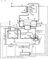
- Fig. 1 is a block diagram of a liquid heating device according to an embodiment.
- the liquid heating device is composed of a use-side heat medium circuit 30, and a refrigeration cycle device which is a supercritical steam compression type refrigeration cycle.
- the refrigeration cycle device is composed of a main refrigerant circuit 10 and a bypass refrigerant circuit 20.
- the main refrigerant circuit 10 is formed by sequentially connecting, to one another through a pipe 16, a compression mechanism 11 which compresses refrigerant, a radiator 12 which is a use-side heat exchanger, an economizer 13 which is an intermediate heat exchanger, a main expansion valve 14 which is a first expanding device, and an evaporator 15 which is a heat source-side heat exchanger.
- Carbon dioxide (CO 2 ) is used as the refrigerant.
- the refrigerant it is optimal to carbon dioxide, but it is also possible to use zeotropic refrigerant mixture such as R407C, pseudo azeotropic refrigerant mixture such as R410A, single refrigerant such as R32, and flammable refrigerant such as propane.
- zeotropic refrigerant mixture such as R407C
- pseudo azeotropic refrigerant mixture such as R410A
- single refrigerant such as R32
- flammable refrigerant such as propane.
- the compression mechanism 11 injects refrigerant from the bypass refrigerant circuit 20 on the way of compression of refrigerant by the rotating element, the compression mechanism 11 makes the refrigerant from the bypass refrigerant circuit 20 and the refrigerant which is on the way of compression merge with each other, and the compression mechanism 11 again compresses them.
- the radiator 12 heats the use-side heat medium by the refrigerant discharged from the compression mechanism 11.
- the bypass refrigerant circuit 20 branches off from the pipe 16 located between the radiator 12 and the main expansion valve 14, and the bypass refrigerant circuit 20 is connected to the compression chamber which is on the way of compression of the compression mechanism 11.
- the bypass refrigerant circuit 20 is provided with a bypass expansion valve 21 which is a second expanding device.
- a portion of high pressure refrigerant after it passes through the radiator 12 or a portion of high pressure refrigerant after it passes through the economizer 13 is decompressed by the bypass expansion valve 21 and becomes intermediate pressure refrigerant.
- the intermediate pressure refrigerant exchanges, in the economizer 13, heat with high pressure refrigerant which flows through the main refrigerant circuit 10, the intermediate pressure refrigerant is injected into the rotating element of the compression mechanism 11, and the intermediate pressure refrigerant merges with refrigerant which is on the way of compression of the main refrigerant circuit 10.
- the use-side heat medium circuit 30 is formed by sequentially connecting the radiator 12, a transfer pump 31 which is a transfer device and heating terminal 32a to one another through a heat medium pipe 33. Water or antifreeze liquid is used as the use-side heat medium.
- the use-side heat medium circuit 30 in the embodiment includes a heating terminal 32a and a hot water tank 32b located in parallel thereto. By switching between a first switching valve 34 and a second switching valve 35, the use-side heat medium is circulated through the heating terminal 32a or the hot water tank 32b. It is only necessary that the use-side heat medium circuit 30 includes any one of the heating terminal 32a and the hot water tank 32b.
- High temperature water produced by the radiator 12 radiates heat in the heating terminal 32a, the heat is used for heating homes, and low temperature water which radiates heat in the heating terminal 32a is again heated by the radiator 12.
- the high temperature water produced by the radiator 12 in introduced into the hot water tank 32b from an upper portion of the hot water tank 32b, low temperature water is derived from a lower portion of the hot water tank 32b and is heated by the radiator 12.
- a hot water supply-heat exchanger 42 is placed in the hot water tank 32b, and exchanges heat between water supplied from the water supply pipe 43 and high temperature water in the hot water tank 32b. That is, if the hot water tap 41 is opened, water is supplied from the water supply pipe 43 into the hot water supply-heat exchanger 42. The water is heated by the hot water supply-heat exchanger 42, temperature of the water is adjusted to a predetermined value by the hot water tap 41, and hot water is supplied from the hot water tap 41. Water is supplied from the water supply pipe 43 and is heated by the hot water supply-heat exchanger 42. Hot water supplied from the hot water tap 41 and high temperature water in the hot water tank 32b are not mixed with each other and they are heated indirectly.
- the hot water supply-heat exchanger 42 is a water heat exchanger using a copper pipe or a stainless pipe as a heattransfer pipe. As shown in Fig. 1 , the hot water supply-heat exchanger 42 is connected to the water supply pipe 43 and the hot water tap 41 extending from a water-supply source (waterline).
- the water supply pipe 43 introduces ordinary temperature water to a lower end of the hot water supply-heat exchanger 42, i.e., to a lower portion in the hot water tank 32b.
- the ordinary temperature water introduced from the water supply pipe 43 into the hot water supply-heat exchanger 42 takes heat from high temperature water in the hot water tank 32b while moving upward from a lower portion in the hot water tank 32b.
- the ordinary temperature water becomes high temperature heated water and is supplied from the hot water tap 41.
- a plurality of hot water tank temperature thermistors measure temperature of hot water at a plurality of different height positions.
- a first hot water tank temperature thermistor 55a, a second hot water tank temperature thermistor 55b and a third hot water tank temperature thermistor 55c are provided.
- the ordinary temperature Water which enters the hot water supply-heat exchanger 42 from the water supply pipe 43 takes heat from high temperature water in the hot water tank 32b while moving upward from a lower portion in the hot water tank 32b. Hence, temperature of the hot water in the hot water tank 32b naturally becomes high in its upper portion and lower in its lower portion.
- the main refrigerant circuit 10 is provided with a high pressure-side pressure detecting device 51 in the pipe 16 on a discharge-side of the compression mechanism 11.
- the high pressure-side pressure detecting device 51 is provided in the main refrigerant circuit 10 from a discharge-side of the compression mechanism 11 to an upstream-side of the main expansion valve 14. It is only necessary that the high pressure-side pressure detecting device 51 can detect the pressure of the high pressure refrigerant of the main refrigerant circuit 10.
- An intermediate heat exchanger main refrigerant inlet thermistor 57 is provided in the pipe 16 on a downstream-side of the use-side heat exchanger 12 of the main refrigerant circuit 10, i.e., on an upstream-side of the economizer 13.
- the intermediate heat exchanger main refrigerant inlet thermistor 57 detects temperature of refrigerant which flows out from the use-side heat exchanger 12.
- the bypass refrigerant circuit 20 is provided with an intermediate heat exchanger bypass inlet thermistor 56.
- the intermediate heat exchanger bypass inlet thermistor 56 detects temperature of refrigerant which flows out from a second expanding device 21 on a downstream-side of the second expanding device 21, i.e., on the upstream side of the economizer 13.
- the use-side heat medium circuit 30 includes a heat medium outlet temperature thermistor 53 and a heat medium inlet temperature thermistor 54.
- the heat medium outlet temperature thermistor 53 detects temperature of use-side heat medium which flows out from the use-side heat exchanger 12.
- the heat medium inlet temperature thermistor 54 detects temperature of use-side heat medium which flows into the use-side heat exchanger 12.
- the bypass refrigerant circuit 20 includes the intermediate heat exchanger bypass inlet thermistor 56, an intermediate heat exchanger bypass outlet thermistor 58 and an intermediate pressure-side pressure detecting device 52.
- the intermediate heat exchanger bypass inlet thermistor 56 detects refrigerant temperature on the upstream side of the economizer 13.
- the intermediate heat exchanger bypass outlet thermistor 58 detects refrigerant temperature on the downstream-side of the economizer 13.
- the intermediate pressure-side pressure detecting device 52 directly or indirectly detects pressure on the downstream side of the second expanding device 21.
- this pressure detecting device 52 directly detects the pressure, this pressure detecting device 52 directly, i.e., mechanically detects pressure of refrigerant.
- a control device 60 calculates a value of pressure (intermediate pressure) of refrigerant after this pressure is reduced by the second expanding device 21 based on detection pressure detected by the high pressure-side pressure detecting device 51 and detection pressure detected by the intermediate heat exchanger main refrigerant inlet thermistor 57. Further, the control device 60 calculates a value of intermediate pressure based on detection temperature detected by the heat medium inlet temperature thermistor 54 and detection temperature detected by the intermediate heat exchanger bypass inlet thermistor 56. The control device 60 has arithmetic processing function.
- control device 60 memorizes a pressure-enthalpy diagram (P-h diagram) as shown in Fig. 2 .
- the high pressure-side pressure detecting device 51 detects, every predetermined time, high pressure-side pressure (discharge pressure of high-stage side compression rotating element 11b), the intermediate heat exchanger main refrigerant inlet thermistor 57 detects, every predetermined time, outlet temperature (point A) of the use-side heat exchanger 12, and the intermediate heat exchanger bypass inlet thermistor 56 detects, every predetermined time, inlet temperature (point e) of refrigerant of the bypass refrigerant circuit 20 of the intermediate heat exchanger 13.
- the control device 60 calculates pressure and the enthalpy at the point e. According to this, it is possible to calculate a value of pressure (intermediate pressure) of refrigerant after the pressure is reduced by the second expanding device 21, and it is possible to determine whether the pressure is equal to or higher than critical pressure by the calculated value.
- pressure (intermediate pressure) of refrigerant after this pressure is reduced by the second expanding device 21 is equal to or higher than the critical pressure based on the discharge pressure of the compression mechanism 11, based on the outlet temperature (point A) of refrigerant of the use-side heat exchanger 12, and based on the inlet temperature (point e) of refrigerant of the bypass refrigerant circuit 20 of the intermediate heat exchanger 13, or based on temperature of the use-side heat medium which flows into the use-side heat exchanger 12.
- the intermediate pressure-side pressure detecting device 52 includes any one of the pressure detecting devices which directly or indirectly detect pressure.
- the control device 60 controls operating frequency of the compression mechanism 11, opening degrees of the main expansion valve 14 and the bypass expansion valve 21, and the transfer pump 31 based on detection pressures detected by the high pressure-side pressure detecting device 51 and the intermediate pressure-side pressure detecting device 52, and based on detection temperatures detected by the heat medium outlet temperature thermistor 53 and the heat medium inlet temperature thermistor 54.
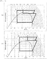
- Figs. 2 are pressure-enthalpy diagrams (P-h diagrams) under an ideal condition concerning a refrigeration cycle device, wherein Fig. 2(a) shows a case in which high pressure is lower than predetermined pressure, and Fig. 2(b) shows a case in which high pressure is equal to or higher than the predetermined pressure. Points a to e and point A to B in Fig. 2 correspond to respective points of the liquid heating device shown in Fig. 1 .
- high pressure refrigerant (point a) discharged from the compression mechanism 11 radiates heat in the radiator 12 and then, the high pressure refrigerant branches off from the main refrigerant circuit 10 at a refrigerant branch point A.
- the high pressure refrigerant is reduced in pressure to intermediate pressure by the bypass expansion valve 21, the pressure becomes equal to the intermediate pressure refrigerant (point e), and the intermediate pressure refrigerant exchanges heat in the economizer 13.
- the high pressure refrigerant which flows through the main refrigerant circuit 10 after it radiates heat in the radiator 12 is cooled by the intermediate pressure refrigerant (point e) which flows through the bypass refrigerant circuit 20, and the refrigerant is reduced in pressure by the main expansion valve 14 in a state where its enthalpy is reduced (point b).
- refrigerant enthalpy of the refrigerant (point c) which flows into the evaporator 15 is also reduced. Dryness of the refrigerant when it flows into the evaporator 15 is lowered, and liquid component of the refrigerant is increased. Hence, this fact contributes to evaporation in the evaporator 15, a ratio of the refrigerant is increased, heat absorption from the outside air is increased, and the refrigerant returns to the suction side (point d) of the compression mechanism 11.
- the dryness of the refrigerant is a ratio of weight occupied by gas phase component with respect to the entire refrigerant.
- refrigerant of an amount corresponding to an amount of gas phase component which does not contribute to evaporation in the evaporator 15 bypasses to the bypass refrigerant circuit 20 and becomes low temperature intermediate pressure refrigerant (point e).
- the intermediate pressure refrigerant is heated by high pressure refrigerant which flows through the main refrigerant circuit 10 in the economizer 13. In a state where refrigerant enthalpy becomes high, the intermediate pressure refrigerant reaches a merging point B of refrigerant which is on the way of compression of the compression mechanism 11.
- Discharge pressure of the compression mechanism 11 rises and exceeds a predetermined value, the control device 60 starts controlling a vale opening degree of the bypass expansion valve 21 such that pressure of refrigerant after it is reduced by the bypass expansion valve 21 exceeds the critical pressure as shown in Fig. 2(b) .
- the control device 60 starts the operation to increase the valve opening degree of the bypass expansion valve 21.
- control device 60 operates to increase the valve opening degree of the bypass expansion valve 21 as shown in Fig. 2(b) .
- the control device 60 increases operating frequency of the compression mechanism 11, and increases a circulation amount of refrigerant which flows through the bypass refrigerant circuit 20.
- the control device 60 controls such that detection pressure detected by the high pressure-side pressure detecting device 51 becomes equal to a second predetermined high pressure value which is a target high pressure value.
- the second predetermined high pressure value is higher than the first predetermined high pressure value.
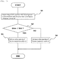
- the control device 60 controls the valve opening degree of the bypass expansion valve 21 as shown in a control flow in Fig. 3 .
- degrees of superheat SHm of refrigerant which is on the way of compression of the compression mechanism 11 and refrigerant before merging are acquired (S1).
- the control device 60 When it is determined that the degrees of superheat SHm are lower than a predetermined value SHt (YES in S2), the control device 60 operates to reduce the valve opening degree of the bypass expansion valve 21 and a flow rate of refrigerant is reduced (S3). According to this, a temperature rising width of refrigerant caused by heat exchange with the main refrigerant circuit 10 is increased and on the downstream side of the economizer 13, the degrees of superheat SHm of the refrigerant which is on the way of compression of the compression mechanism 11 and the refrigerant before merging rise. Hence, refrigerant which is injected to the compression mechanism 11 becomes gas.
- the control device 60 When it is determined that the acquired degree of superheat SHm of refrigerant on the downstream side of the economizer 13 exceeds the predetermined value SHt (NO in S2), the control device 60 operates to increase the valve opening degree of the bypass expansion valve 21, and the flow rate of refrigerant is increased (S4). According to this, the temperature rising width of refrigerant caused by heat exchange with the main refrigerant circuit 10 becomes small and on the downstream side of the economizer 13, the degrees of superheat SHm of the refrigerant which is on the way of compression of the compression mechanism 11 and the refrigerant before the merging are reduced. Further, temperature of refrigerant which merges with the main refrigerant circuit 10 on the way of compression of the compression mechanism 11 is lowered, and discharge temperature which is temperature of refrigerant discharged from the compression mechanism 11 is lowered.
- the degree of superheat SHm of refrigerant injected into the compression mechanism 11 can be calculated from a difference between temperature obtained from the intermediate heat exchanger bypass inlet thermistor 56 and temperature obtained from the intermediate heat exchanger bypass outlet thermistor 58 while taking pressure loss of the economizer 13 into account. This is because that when pressure (intermediate pressure) of refrigerant after it is reduced by the second expanding device 21 is lower than the critical pressure, temperature detected by the intermediate heat exchanger bypass inlet thermistor 56 becomes saturated temperature.
- the degree of superheat SHm can also be calculated from pressure information detected by the intermediate pressure-side pressure detecting device 52 and temperature information detected by the intermediate heat exchanger bypass outlet thermistor 58.
- the first hot water tank temperature thermistor 55a is positioned at the highest position in the hot water tank 32b. For example, when detection temperature detected by the first hot water tank temperature thermistor 55a is lower than the predetermined value, the control device 60 determines that high temperature water is insufficient in the hot water tank 32b.
- control device 60 operates the compression mechanism 11 and heats low temperature water by the radiator 12. According to this, the transfer pump 31 is operated such that detection temperature detected by the heat medium outlet temperature thermistor 53 which is heated produced temperature becomes equal to target temperature.
- low temperature water derived from the lower portion in the hot water tank 32b is heated by the radiator 12. According to this, high temperature water is produced, and the produced high temperature water is introduced into the hot water tank 32b from the upper portion in the hot water tank 32b. At that time, since the detection temperature detected by the heat medium inlet temperature thermistor 54 is equal to or lower than third predetermined temperature, the transfer pump 31 is operated in the state shown in Fig. 2(a) .
- control device 60 controls such that the valve opening degree of the bypass expansion valve 21 is increased, and the operating frequency of the compression mechanism 11 is increased, thus the circulation amount of refrigerant flowing through the bypass refrigerant circuit 20 is increased, and detection pressure detected by the high pressure-side pressure detecting device 51 becomes equal to the second predetermined high pressure which is the target high pressure value.
- control device 60 operates such that detection pressure detected by the intermediate pressure-side pressure detecting device 52 becomes equal to predetermined intermediate pressure which is the target intermediate pressure value.
- inlet temperature of heat medium entering the radiator 12 becomes high, and an enthalpy difference (a-A) of refrigerant in the radiator 12 becomes small.
- a-A enthalpy difference
- heating ability of refrigerant in the radiator 12 is enhanced. According to this, it is possible to keep supplying the high temperature water to the hot water tank 32b.
- the control device 60 reduces the operating frequency of the compression mechanism 11. According to this, it is possible to store the high temperature water in the hot water tank 32b such that pressure of high pressure refrigerant in the radiator 12 does not exceeds the second predetermined high pressure value which is the target high pressure value while suppressing the pressure rise of the high pressure refrigerant in the radiator 12.
- the same operating action may be executed respectively using the first predetermined high pressure value and the second predetermined high pressure value which are detection pressures detected by the high pressure-side pressure detecting device 51 as the threshold values instead of using the third predetermined temperature and the first predetermined temperature which are detection temperatures detected by the heat medium inlet temperature thermistor 54.
- the control device 60 operates the compression mechanism 11 and heats circulating water by the radiator 12.
- the control device 60 operates the transfer pump 31 such that a temperature difference between the detection temperature detected by the heat medium outlet temperature thermistor 53 and the detection temperature detected by the heat medium inlet temperature thermistor 54 becomes equal to the target temperature difference.
- high temperature water produced by the radiator 12 radiates heat in the heating terminal 32a, and the heat is used for heating homes, and low temperature water which radiates heat in the heating terminal 32a is again heated by the radiator 12.
- control is performed such that the temperature difference between the detection temperature detected by the heat medium outlet temperature thermistor 53 and the detection temperature detected by the heat medium inlet temperature thermistor 54 becomes equal to the target temperature difference.
- the transfer pump 31 is operated in the state shown in Fig. 2(a) .
- the home-heating load gradually becomes small. Therefore, since the control is performed such that the temperature difference between the detection temperature detected by the heat medium outlet temperature thermistor 53 and the detection temperature detected by the heat medium inlet temperature thermistor 54 becomes equal to the target temperature difference, the detection temperature detected by the heat medium outlet temperature thermistor 53 and the detection temperature detected by the heat medium inlet temperature thermistor 54 are gradually rising. Thereafter, when the detection temperature detected by the heat medium outlet temperature thermistor 53 exceeds the fourth predetermined temperature, the transfer pump 31 is operated in the state shown in Fig. 2(b) .
- control device 60 controls such that the valve opening degree of the bypass expansion valve 21 is increased, and the operating frequency of the compression mechanism 11 is increased, thus the circulation amount of refrigerant flowing through the bypass refrigerant circuit 20 is increased, and the detection pressure detected by the high pressure-side pressure detecting device 51 becomes equal to the second predetermined high pressure value which is the target high pressure value.
- the control device 60 controls the valve opening degree of the bypass expansion valve 21 as shown in the control flowchart shown in Fig. 3 .
- the degrees of superheat SHm of the refrigerant on the way of compression of the compression mechanism 11 and refrigerant before merging are acquired (S1).
- the control device 60 operates to reduce the valve opening degree of the bypass expansion valve 21, and the flow rate of refrigerant is reduced (S3).
- the temperature rising width of refrigerant caused by heat exchange with the main refrigerant circuit 10 becomes large, and the degrees of superheat SHm of refrigerant on the way of compression of the compression mechanism 11 and the refrigerant before merging rise on the downstream side of the economizer 13. Therefore, refrigerant injected into the compression mechanism 11 becomes gas.
- the control device 60 operates to increase the valve opening degree of the bypass expansion valve 21, and the flow rate of refrigerant is increased (S4).
- the temperature rising width of the refrigerant caused by the heat exchange with the main refrigerant circuit 10 becomes small, the degrees of superheat SHm of the refrigerant on the way of compression of the compression mechanism 11 and the refrigerant before merging are lowered, temperature of refrigerant which merges with the main refrigerant circuit 10 on the way of compression of the compression mechanism 11 is lowered, and discharge temperature which is temperature of refrigerant discharged from the compression mechanism 11 is lowered.
- the degree of superheat SHm of refrigerant injected into the compression mechanism 11 can be calculated from a difference between temperature obtained by the intermediate heat exchanger bypass inlet thermistor 56 and temperature obtained by the intermediate heat exchanger bypass outlet thermistor 58 while taking the pressure loss of the economizer 13 into account. This is because that when pressure (intermediate pressure) of refrigerant after it is reduced by the second expanding device 21 is lower than the critical pressure, temperature detected by the intermediate heat exchanger bypass inlet thermistor 56 becomes the saturated temperature.
- the degree of superheat SHm of refrigerant injected into the compression mechanism 11 can also be calculated from pressure information detected by the intermediate pressure-side pressure detecting device 52 and temperature information detected by the intermediate heat exchanger bypass outlet thermistor 58.
- the home-heating load becomes small, and the enthalpy difference (a-A) of refrigerant in the radiator 12 becomes small.
- the heating ability of refrigerant in the radiator 12 is enhanced. According to this, it is possible to keep supplying high temperature water to the heating terminal 32a.
- the control device 60 reduces the operating frequency of the compression mechanism 11. According to this, it is possible to utilize the liquid heating device as a home-heating device using high temperature water while suppressing the pressure rise of high pressure refrigerant in the radiator 12 such that pressure of the high pressure refrigerant in the radiator 12 does not exceed the second predetermined high pressure value which is the target high pressure value.
- the predetermined value SHt which operates to increase the valve opening degree of the bypass expansion valve 21 and the predetermined value SHt which operates to reduce the valve opening degree of the bypass expansion valve 21 may be the same or different from each other. That is, the predetermined value SHt which operates to increase the valve opening degree of the bypass expansion valve 21 may be higher than the predetermined value SHt which operates to reduce the valve opening degree of the bypass expansion valve 21.
- the same operating action may be executed using the first predetermined high pressure value and the second predetermined high pressure value which are detection pressures detected by the high pressure-side pressure detecting device 51 as the threshold values instead of using the fourth predetermined temperature and the second predetermined temperature which are detection temperatures detected by the heat medium outlet temperature thermistor 53.
- carbon dioxide is used as the refrigerant. This is because that temperature of the use-side heat medium can be made high in the radiator 12 when the use-side heat medium is heated by the carbon dioxide which is the refrigerant.
- high temperature water can be used the heating terminal 32a or can be stored in the hot water tank 32b.
- the refrigeration cycle device of the present invention includes the main refrigerant circuit having the intermediate heat exchanger and the bypass refrigerant circuit.
- the degree of superheat of refrigerant injected from the bypass refrigerant circuit into the compression mechanism equal to or higher than the predetermined value, it is possible to prevent liquid compression from being generated in the compression mechanism.
- the present invention is useful for a liquid heating device of a refrigerator, an air conditioner, hot water supply system and a home-heating device using the refrigeration cycle device.
Landscapes
- Engineering & Computer Science (AREA)
- Physics & Mathematics (AREA)
- Mechanical Engineering (AREA)
- Thermal Sciences (AREA)
- General Engineering & Computer Science (AREA)
- Chemical & Material Sciences (AREA)
- Chemical Kinetics & Catalysis (AREA)
- Heat-Pump Type And Storage Water Heaters (AREA)
Abstract
Description
- The present invention relates to a refrigeration cycle device and a liquid heating device having the same.
-
Patent document 1 discloses a supercritical steam compression type refrigeration cycle including a compressor which compresses refrigerant in two stages, and two expanding devices which expand refrigerant in two stages. Carbon dioxide is used as refrigerant. - The supercritical steam compression type refrigeration cycle of
patent document 1 includes a gas-liquid separator. Refrigerant having gas phase in the gas-liquid separator as main component is intermediately injected into a refrigerant mixer located on the way to an intermediate connection circuit of the compressor from the injection circuit. The refrigerant is mixed into refrigerant discharged from a low-stage side rotation compression rotating element, and the mixed refrigerant is sucked into a high-stage side rotation compression rotating element. - In
patent document 1, a ratio (displacement capacity ratio) of displacement capacity of the high-stage side rotation compression rotating element in comparison with displacement capacity of the low-stage side rotation compression rotating element is equal to or higher than isentropic index root of quotient obtained by dividing suction pressure of the compressor by refrigerant saturated liquid pressure in a first expanding device. According to this, discharge pressure of the low-stage side rotation compression rotating element is set equal to or lower than critical pressure of the refrigerant. - Further, as refrigerant,
patent document 2 uses refrigerant other than carbon dioxide.Patent document 2 discloses a refrigeration device including a compressor which compresses refrigerant in two stages, and two expanding devices which expand refrigerant in two stages. - The refrigeration device of
patent document 2 includes a supercooling heat exchanger and an injection circuit. The injection circuit decompresses a portion of refrigerant discharged from the compressor by a bypass expansion valve, and the decompressed refrigerant is heated by the supercooling heat exchanger. Thereafter, the heated decompressed refrigerant is injected into the intermediate port which is in communication with a low-stage side and a high-stage side of the compressor. Refrigerant from the injection circuit and refrigerant discharged from the low stage are mixed with each other in the intermediate port. The mixed refrigerant is sucked into the high-stage side rotating element. An opening degree of the bypass expansion valve is adjusted in accordance with a degree of superheat of the sucked refrigerant, thereby preventing liquid from returning to the compressor. -
- [Patent Document 1]
Japanese Patent Application Laid-open No.2010-071643 - [Patent Document 2]
Japanese Patent Application Laid-open No.2009-192164 - However, according to the above-described conventional configuration, the intermediate port is connected directly to a compression chamber of the compressor, and refrigerant which passes through the supercooling heat exchanger (intermediate heat exchanger) is injected into the compression chamber. In the case of the compressor having such a configuration that injected refrigerant and refrigerant which is on the way to be compressed are mixed in the compression chamber and again compressed in this way, if the injected refrigerant is liquid refrigerant, there is a problem that liquid back is generated, and reliability of the compressor is deteriorated. Further, it is difficult to directly measure a degree of superheat of refrigerant which is obtained after refrigerant injected in the compression chamber and refrigerant which is on the way to be compressed are mixed with each other.
- The present invention is for solving the above problem, and it is an object of the invention to provide a reliable refrigeration cycle device which prevents liquid back by bringing, equal to or higher than a predetermined value, a degree of superheat of refrigerant after it passes through an intermediate heat exchanger. It is another object of the invention to provide a liquid heating device having the above-described refrigeration cycle device.
- To solve the conventional problem, a refrigeration cycle device of the present invention including: a main refrigerant circuit formed by sequentially connecting, to one another through a pipe, a compression mechanism composed of a compression rotating element, a use-side heat exchanger for heating use-side heat medium by refrigerant discharged from the compression rotating element, an intermediate heat exchanger, a first expanding device and a heat source-side heat exchanger; a bypass refrigerant circuit which branches off from the pipe between the use-side heat exchanger and the first expanding device, in which after the refrigerant which is branched is decompressed by a second expanding device, the branched refrigerant exchanges heat, in the intermediate heat exchanger, with the refrigerant flowing through the main refrigerant circuit, and merges with refrigerant which is on the way of compression of the compression rotating element; a pre-cooling temperature sensor for detecting temperature of the refrigerant flowing through the bypass refrigerant circuit located upstream of the intermediate heat exchanger; a post-cooling temperature sensor for detecting temperature of the refrigerant flowing through the bypass refrigerant circuit located downstream of the intermediate heat exchanger; and a control device, wherein the control device calculates a degree of superheat of the refrigerant which merges with the compression rotating element based on temperature data acquired from the pre-cooling temperature sensor and from the post-cooling temperature sensor, and when the calculated degree of superheat is lower than a predetermined value, the control device operates to reduce a valve opening degree of the second expanding device.
- According to this, it is possible to prevent the liquid back which is generated when liquid refrigerant is mixed into the compression chamber of the compression rotating element.
- According to the present invention, it is possible to prevent the increase of the vibration of a compression mechanism which is caused by generation of the liquid back, and it is possible to secure the reliability of the compression mechanism. Especially, when the second expansion valve is opened to a predetermined position at the time of actuation, it is possible to prevent refrigerant from being gasified and from being injected while keeping its liquid state. Hence, it is possible to provide a reliable refrigeration cycle device and a liquid heating device having the same.
-
-
Fig. 1 is a block diagram of a liquid heating device according to an embodiment of the present invention; -
Figs. 2(a) and (b) are pressure-enthalpy diagrams (P-h diagrams) under an ideal condition concerning a refrigeration cycle device; and -
Fig. 3 is a flowchart of control of a bypass expansion valve in the embodiment. - In a refrigeration cycle in which refrigerant heated by an inter-cooler is injected into a compression chamber, an optimum injection amount differs depending upon outside temperature and water temperature at the time of operation. Hence, it is a general control method to adjust the injection amount of refrigerant by a pressure reducing valve. However, when the injection amount is adjusted, the injection amount of refrigerant becomes too much, intermediate pressure-side refrigerant cannot entirely evaporate and flows into the compressor in its liquid state. Therefore, liquid compression is generated, and reliability of the compressor is deteriorated in some cases. Generally, to secure the reliability of the compressor, control is performed to prevent the liquid compression on the suction side. Not only that, in the case of a refrigeration cycle in which injection is carried out, it is necessary to also take the liquid compression in the injection. To solve this problem, the subject matter of the present disclosure is configured.
- The present disclosure provides a reliable refrigeration cycle device which prevents liquid back of refrigerant which is injected after it passes through an intermediate heat exchanger, and also provides a liquid heating device having the same.
- An embodiment will be described in detail below with reference to the drawings. However, description which is detail more than necessary will be omitted in some cases. For example, detailed description of already well known matters, or redundant description of substantially the same configuration will be omitted in some cases. This is for preventing the following description from becoming redundant more than necessary, and for making it easy for a person skilled in the art to understand the present disclosure.
- The accompanying drawing and the following description are provided so that a person skilled in the art can sufficiently understand the present disclosure, and it is not intended that they limit the subject matter described in claims.
-
Fig. 1 is a block diagram of a liquid heating device according to an embodiment. The liquid heating device is composed of a use-sideheat medium circuit 30, and a refrigeration cycle device which is a supercritical steam compression type refrigeration cycle. The refrigeration cycle device is composed of amain refrigerant circuit 10 and abypass refrigerant circuit 20. - The
main refrigerant circuit 10 is formed by sequentially connecting, to one another through apipe 16, acompression mechanism 11 which compresses refrigerant, aradiator 12 which is a use-side heat exchanger, aneconomizer 13 which is an intermediate heat exchanger, amain expansion valve 14 which is a first expanding device, and anevaporator 15 which is a heat source-side heat exchanger. Carbon dioxide (CO2) is used as the refrigerant. - As the refrigerant, it is optimal to carbon dioxide, but it is also possible to use zeotropic refrigerant mixture such as R407C, pseudo azeotropic refrigerant mixture such as R410A, single refrigerant such as R32, and flammable refrigerant such as propane.
- The
compression mechanism 11 injects refrigerant from thebypass refrigerant circuit 20 on the way of compression of refrigerant by the rotating element, thecompression mechanism 11 makes the refrigerant from thebypass refrigerant circuit 20 and the refrigerant which is on the way of compression merge with each other, and thecompression mechanism 11 again compresses them. Theradiator 12 heats the use-side heat medium by the refrigerant discharged from thecompression mechanism 11. - The
bypass refrigerant circuit 20 branches off from thepipe 16 located between theradiator 12 and themain expansion valve 14, and thebypass refrigerant circuit 20 is connected to the compression chamber which is on the way of compression of thecompression mechanism 11. - The
bypass refrigerant circuit 20 is provided with abypass expansion valve 21 which is a second expanding device. A portion of high pressure refrigerant after it passes through theradiator 12 or a portion of high pressure refrigerant after it passes through theeconomizer 13 is decompressed by thebypass expansion valve 21 and becomes intermediate pressure refrigerant. Thereafter, the intermediate pressure refrigerant exchanges, in theeconomizer 13, heat with high pressure refrigerant which flows through the mainrefrigerant circuit 10, the intermediate pressure refrigerant is injected into the rotating element of thecompression mechanism 11, and the intermediate pressure refrigerant merges with refrigerant which is on the way of compression of the mainrefrigerant circuit 10. - The use-side
heat medium circuit 30 is formed by sequentially connecting theradiator 12, atransfer pump 31 which is a transfer device andheating terminal 32a to one another through aheat medium pipe 33. Water or antifreeze liquid is used as the use-side heat medium. - The use-side
heat medium circuit 30 in the embodiment includes aheating terminal 32a and ahot water tank 32b located in parallel thereto. By switching between afirst switching valve 34 and asecond switching valve 35, the use-side heat medium is circulated through theheating terminal 32a or thehot water tank 32b. It is only necessary that the use-sideheat medium circuit 30 includes any one of theheating terminal 32a and thehot water tank 32b. - High temperature water produced by the
radiator 12 radiates heat in theheating terminal 32a, the heat is used for heating homes, and low temperature water which radiates heat in theheating terminal 32a is again heated by theradiator 12. - The high temperature water produced by the
radiator 12 in introduced into thehot water tank 32b from an upper portion of thehot water tank 32b, low temperature water is derived from a lower portion of thehot water tank 32b and is heated by theradiator 12. - A hot water supply-
heat exchanger 42 is placed in thehot water tank 32b, and exchanges heat between water supplied from thewater supply pipe 43 and high temperature water in thehot water tank 32b. That is, if thehot water tap 41 is opened, water is supplied from thewater supply pipe 43 into the hot water supply-heat exchanger 42. The water is heated by the hot water supply-heat exchanger 42, temperature of the water is adjusted to a predetermined value by thehot water tap 41, and hot water is supplied from thehot water tap 41. Water is supplied from thewater supply pipe 43 and is heated by the hot water supply-heat exchanger 42. Hot water supplied from thehot water tap 41 and high temperature water in thehot water tank 32b are not mixed with each other and they are heated indirectly. - The hot water supply-
heat exchanger 42 is a water heat exchanger using a copper pipe or a stainless pipe as a heattransfer pipe. As shown inFig. 1 , the hot water supply-heat exchanger 42 is connected to thewater supply pipe 43 and thehot water tap 41 extending from a water-supply source (waterline). Thewater supply pipe 43 introduces ordinary temperature water to a lower end of the hot water supply-heat exchanger 42, i.e., to a lower portion in thehot water tank 32b. The ordinary temperature water introduced from thewater supply pipe 43 into the hot water supply-heat exchanger 42 takes heat from high temperature water in thehot water tank 32b while moving upward from a lower portion in thehot water tank 32b. The ordinary temperature water becomes high temperature heated water and is supplied from thehot water tap 41. - In the
hot water tank 32b, a plurality of hot water tank temperature thermistors measure temperature of hot water at a plurality of different height positions. For example, a first hot water tank temperature thermistor 55a, a second hot watertank temperature thermistor 55b and a third hot water tank temperature thermistor 55c are provided. The ordinary temperature Water which enters the hot water supply-heat exchanger 42 from thewater supply pipe 43 takes heat from high temperature water in thehot water tank 32b while moving upward from a lower portion in thehot water tank 32b. Hence, temperature of the hot water in thehot water tank 32b naturally becomes high in its upper portion and lower in its lower portion. - The main
refrigerant circuit 10 is provided with a high pressure-sidepressure detecting device 51 in thepipe 16 on a discharge-side of thecompression mechanism 11. The high pressure-sidepressure detecting device 51 is provided in the mainrefrigerant circuit 10 from a discharge-side of thecompression mechanism 11 to an upstream-side of themain expansion valve 14. It is only necessary that the high pressure-sidepressure detecting device 51 can detect the pressure of the high pressure refrigerant of the mainrefrigerant circuit 10. - An intermediate heat exchanger main
refrigerant inlet thermistor 57 is provided in thepipe 16 on a downstream-side of the use-side heat exchanger 12 of the mainrefrigerant circuit 10, i.e., on an upstream-side of theeconomizer 13. The intermediate heat exchanger mainrefrigerant inlet thermistor 57 detects temperature of refrigerant which flows out from the use-side heat exchanger 12. Further, thebypass refrigerant circuit 20 is provided with an intermediate heat exchangerbypass inlet thermistor 56. The intermediate heat exchangerbypass inlet thermistor 56 detects temperature of refrigerant which flows out from a second expandingdevice 21 on a downstream-side of the second expandingdevice 21, i.e., on the upstream side of theeconomizer 13. - The use-side
heat medium circuit 30 includes a heat mediumoutlet temperature thermistor 53 and a heat mediuminlet temperature thermistor 54. The heat mediumoutlet temperature thermistor 53 detects temperature of use-side heat medium which flows out from the use-side heat exchanger 12. The heat mediuminlet temperature thermistor 54 detects temperature of use-side heat medium which flows into the use-side heat exchanger 12. - Further, the
bypass refrigerant circuit 20 includes the intermediate heat exchangerbypass inlet thermistor 56, an intermediate heat exchangerbypass outlet thermistor 58 and an intermediate pressure-sidepressure detecting device 52. The intermediate heat exchangerbypass inlet thermistor 56 detects refrigerant temperature on the upstream side of theeconomizer 13. The intermediate heat exchangerbypass outlet thermistor 58 detects refrigerant temperature on the downstream-side of theeconomizer 13. The intermediate pressure-sidepressure detecting device 52 directly or indirectly detects pressure on the downstream side of the second expandingdevice 21. - When the intermediate pressure-side
pressure detecting device 52 directly detects the pressure, thispressure detecting device 52 directly, i.e., mechanically detects pressure of refrigerant. - When the intermediate pressure-side
pressure detecting device 52 indirectly detects the pressure, acontrol device 60 calculates a value of pressure (intermediate pressure) of refrigerant after this pressure is reduced by the second expandingdevice 21 based on detection pressure detected by the high pressure-sidepressure detecting device 51 and detection pressure detected by the intermediate heat exchanger mainrefrigerant inlet thermistor 57. Further, thecontrol device 60 calculates a value of intermediate pressure based on detection temperature detected by the heat mediuminlet temperature thermistor 54 and detection temperature detected by the intermediate heat exchangerbypass inlet thermistor 56. Thecontrol device 60 has arithmetic processing function. - That is, the
control device 60 memorizes a pressure-enthalpy diagram (P-h diagram) as shown inFig. 2 . - The high pressure-side
pressure detecting device 51 detects, every predetermined time, high pressure-side pressure (discharge pressure of high-stage side compression rotating element 11b), the intermediate heat exchanger mainrefrigerant inlet thermistor 57 detects, every predetermined time, outlet temperature (point A) of the use-side heat exchanger 12, and the intermediate heat exchangerbypass inlet thermistor 56 detects, every predetermined time, inlet temperature (point e) of refrigerant of thebypass refrigerant circuit 20 of theintermediate heat exchanger 13. - Based on an ideal condition that enthalpies at the point A and the point e are substantially the same, the
control device 60 calculates pressure and the enthalpy at the point e. According to this, it is possible to calculate a value of pressure (intermediate pressure) of refrigerant after the pressure is reduced by the second expandingdevice 21, and it is possible to determine whether the pressure is equal to or higher than critical pressure by the calculated value. - It is possible to use detection temperature which is detected by the heat medium
inlet temperature thermistor 54 instead of using the detection value detected by the intermediate heat exchanger mainrefrigerant inlet thermistor 57 because these values are substantially the same. - That is, it is possible to determine that pressure (intermediate pressure) of refrigerant after this pressure is reduced by the second expanding
device 21 is equal to or higher than the critical pressure based on the discharge pressure of thecompression mechanism 11, based on the outlet temperature (point A) of refrigerant of the use-side heat exchanger 12, and based on the inlet temperature (point e) of refrigerant of thebypass refrigerant circuit 20 of theintermediate heat exchanger 13, or based on temperature of the use-side heat medium which flows into the use-side heat exchanger 12. - It is only necessary that the intermediate pressure-side
pressure detecting device 52 includes any one of the pressure detecting devices which directly or indirectly detect pressure. - The
control device 60 controls operating frequency of thecompression mechanism 11, opening degrees of themain expansion valve 14 and thebypass expansion valve 21, and thetransfer pump 31 based on detection pressures detected by the high pressure-sidepressure detecting device 51 and the intermediate pressure-sidepressure detecting device 52, and based on detection temperatures detected by the heat mediumoutlet temperature thermistor 53 and the heat mediuminlet temperature thermistor 54. -
Figs. 2 are pressure-enthalpy diagrams (P-h diagrams) under an ideal condition concerning a refrigeration cycle device, whereinFig. 2(a) shows a case in which high pressure is lower than predetermined pressure, andFig. 2(b) shows a case in which high pressure is equal to or higher than the predetermined pressure. Points a to e and point A to B inFig. 2 correspond to respective points of the liquid heating device shown inFig. 1 . - Action of the refrigeration cycle device will be described using
Figs. 2 . - First, high pressure refrigerant (point a) discharged from the
compression mechanism 11 radiates heat in theradiator 12 and then, the high pressure refrigerant branches off from the mainrefrigerant circuit 10 at a refrigerant branch point A. The high pressure refrigerant is reduced in pressure to intermediate pressure by thebypass expansion valve 21, the pressure becomes equal to the intermediate pressure refrigerant (point e), and the intermediate pressure refrigerant exchanges heat in theeconomizer 13. - The high pressure refrigerant which flows through the main
refrigerant circuit 10 after it radiates heat in theradiator 12 is cooled by the intermediate pressure refrigerant (point e) which flows through thebypass refrigerant circuit 20, and the refrigerant is reduced in pressure by themain expansion valve 14 in a state where its enthalpy is reduced (point b). - According to this, after the pressure is reduced by the
main expansion valve 14, refrigerant enthalpy of the refrigerant (point c) which flows into theevaporator 15 is also reduced. Dryness of the refrigerant when it flows into theevaporator 15 is lowered, and liquid component of the refrigerant is increased. Hence, this fact contributes to evaporation in theevaporator 15, a ratio of the refrigerant is increased, heat absorption from the outside air is increased, and the refrigerant returns to the suction side (point d) of thecompression mechanism 11. The dryness of the refrigerant is a ratio of weight occupied by gas phase component with respect to the entire refrigerant. - On the other hand, refrigerant of an amount corresponding to an amount of gas phase component which does not contribute to evaporation in the
evaporator 15 bypasses to thebypass refrigerant circuit 20 and becomes low temperature intermediate pressure refrigerant (point e). The intermediate pressure refrigerant is heated by high pressure refrigerant which flows through the mainrefrigerant circuit 10 in theeconomizer 13. In a state where refrigerant enthalpy becomes high, the intermediate pressure refrigerant reaches a merging point B of refrigerant which is on the way of compression of thecompression mechanism 11. - Therefore, at the merging point (point B) of the
compression mechanism 11, since the refrigerant pressure is higher than that on the suction side (point d) of thecompression mechanism 11, refrigerant density is higher. At the same time, refrigerant which merges with refrigerant which is on the way of compression of thecompression mechanism 11 is further compressed by thecompression mechanism 11 and discharged. Hence, a flow rate of the refrigerant which flows into theradiator 12 is largely increased, and ability for heating water which is the use-side heat medium is largely enhanced. - Discharge pressure of the
compression mechanism 11 rises and exceeds a predetermined value, thecontrol device 60 starts controlling a vale opening degree of thebypass expansion valve 21 such that pressure of refrigerant after it is reduced by thebypass expansion valve 21 exceeds the critical pressure as shown inFig. 2(b) . - More specifically, when it is determined that the detection pressure detected by the high pressure-side
pressure detecting device 51 rises and exceeds a first predetermined high pressure value, if detection pressure detected by the intermediate pressure-sidepressure detecting device 52 is equal to or lower than the critical pressure, thecontrol device 60 starts the operation to increase the valve opening degree of thebypass expansion valve 21. - Then, the
control device 60 operates to increase the valve opening degree of thebypass expansion valve 21 as shown inFig. 2(b) . At the same time, thecontrol device 60 increases operating frequency of thecompression mechanism 11, and increases a circulation amount of refrigerant which flows through thebypass refrigerant circuit 20. According to this, thecontrol device 60 controls such that detection pressure detected by the high pressure-sidepressure detecting device 51 becomes equal to a second predetermined high pressure value which is a target high pressure value. The second predetermined high pressure value is higher than the first predetermined high pressure value. - At the same time, as shown in
Fig. 2(a) , when pressure (intermediate pressure) of refrigerant after it is reduced by the second expandingdevice 21 is lower than the critical pressure, thecontrol device 60 controls the valve opening degree of thebypass expansion valve 21 as shown in a control flow inFig. 3 . On the downstream side of theeconomizer 13 of thebypass refrigerant circuit 20, degrees of superheat SHm of refrigerant which is on the way of compression of thecompression mechanism 11 and refrigerant before merging are acquired (S1). When it is determined that the degrees of superheat SHm are lower than a predetermined value SHt (YES in S2), thecontrol device 60 operates to reduce the valve opening degree of thebypass expansion valve 21 and a flow rate of refrigerant is reduced (S3). According to this, a temperature rising width of refrigerant caused by heat exchange with the mainrefrigerant circuit 10 is increased and on the downstream side of theeconomizer 13, the degrees of superheat SHm of the refrigerant which is on the way of compression of thecompression mechanism 11 and the refrigerant before merging rise. Hence, refrigerant which is injected to thecompression mechanism 11 becomes gas. When it is determined that the acquired degree of superheat SHm of refrigerant on the downstream side of theeconomizer 13 exceeds the predetermined value SHt (NO in S2), thecontrol device 60 operates to increase the valve opening degree of thebypass expansion valve 21, and the flow rate of refrigerant is increased (S4). According to this, the temperature rising width of refrigerant caused by heat exchange with the mainrefrigerant circuit 10 becomes small and on the downstream side of theeconomizer 13, the degrees of superheat SHm of the refrigerant which is on the way of compression of thecompression mechanism 11 and the refrigerant before the merging are reduced. Further, temperature of refrigerant which merges with the mainrefrigerant circuit 10 on the way of compression of thecompression mechanism 11 is lowered, and discharge temperature which is temperature of refrigerant discharged from thecompression mechanism 11 is lowered. - At that time, the degree of superheat SHm of refrigerant injected into the
compression mechanism 11 can be calculated from a difference between temperature obtained from the intermediate heat exchangerbypass inlet thermistor 56 and temperature obtained from the intermediate heat exchangerbypass outlet thermistor 58 while taking pressure loss of theeconomizer 13 into account. This is because that when pressure (intermediate pressure) of refrigerant after it is reduced by the second expandingdevice 21 is lower than the critical pressure, temperature detected by the intermediate heat exchangerbypass inlet thermistor 56 becomes saturated temperature. The degree of superheat SHm can also be calculated from pressure information detected by the intermediate pressure-sidepressure detecting device 52 and temperature information detected by the intermediate heat exchangerbypass outlet thermistor 58. - Action when the
hot water tank 32b is used in the use-sideheat medium circuit 30 will be described below. - Of the plurality of hot water tank temperature thermistors, the first hot water tank temperature thermistor 55a is positioned at the highest position in the
hot water tank 32b. For example, when detection temperature detected by the first hot water tank temperature thermistor 55a is lower than the predetermined value, thecontrol device 60 determines that high temperature water is insufficient in thehot water tank 32b. - Thus, the
control device 60 operates thecompression mechanism 11 and heats low temperature water by theradiator 12. According to this, thetransfer pump 31 is operated such that detection temperature detected by the heat mediumoutlet temperature thermistor 53 which is heated produced temperature becomes equal to target temperature. - According to this, low temperature water derived from the lower portion in the
hot water tank 32b is heated by theradiator 12. According to this, high temperature water is produced, and the produced high temperature water is introduced into thehot water tank 32b from the upper portion in thehot water tank 32b. At that time, since the detection temperature detected by the heat mediuminlet temperature thermistor 54 is equal to or lower than third predetermined temperature, thetransfer pump 31 is operated in the state shown inFig. 2(a) . - Since high temperature water is gradually stored in the
hot water tank 32b from above, detection temperature detected by the heat mediuminlet temperature thermistor 54 is gradually rising. Thereafter, when the detection temperature detected by the heat mediuminlet temperature thermistor 54 exceeds the third predetermined temperature, thetransfer pump 31 is operated in the state shown inFig. 2(b) . - That is, the
control device 60 controls such that the valve opening degree of thebypass expansion valve 21 is increased, and the operating frequency of thecompression mechanism 11 is increased, thus the circulation amount of refrigerant flowing through thebypass refrigerant circuit 20 is increased, and detection pressure detected by the high pressure-sidepressure detecting device 51 becomes equal to the second predetermined high pressure which is the target high pressure value. At the same time, thecontrol device 60 operates such that detection pressure detected by the intermediate pressure-sidepressure detecting device 52 becomes equal to predetermined intermediate pressure which is the target intermediate pressure value. - According to this, inlet temperature of heat medium entering the
radiator 12 becomes high, and an enthalpy difference (a-A) of refrigerant in theradiator 12 becomes small. To compensate this reduced enthalpy difference, heating ability of refrigerant in theradiator 12 is enhanced. According to this, it is possible to keep supplying the high temperature water to thehot water tank 32b. - When the detection temperature detected by the heat medium
inlet temperature thermistor 54 exceeds the first predetermined temperature which is higher than the third predetermined temperature, thecontrol device 60 reduces the operating frequency of thecompression mechanism 11. According to this, it is possible to store the high temperature water in thehot water tank 32b such that pressure of high pressure refrigerant in theradiator 12 does not exceeds the second predetermined high pressure value which is the target high pressure value while suppressing the pressure rise of the high pressure refrigerant in theradiator 12. - The same operating action may be executed respectively using the first predetermined high pressure value and the second predetermined high pressure value which are detection pressures detected by the high pressure-side
pressure detecting device 51 as the threshold values instead of using the third predetermined temperature and the first predetermined temperature which are detection temperatures detected by the heat mediuminlet temperature thermistor 54. - A case where the
heating terminal 32a is used in the use-sideheat medium circuit 30 will be described. - The
control device 60 operates thecompression mechanism 11 and heats circulating water by theradiator 12. Thecontrol device 60 operates thetransfer pump 31 such that a temperature difference between the detection temperature detected by the heat mediumoutlet temperature thermistor 53 and the detection temperature detected by the heat mediuminlet temperature thermistor 54 becomes equal to the target temperature difference. - According to this, high temperature water produced by the
radiator 12 radiates heat in theheating terminal 32a, and the heat is used for heating homes, and low temperature water which radiates heat in theheating terminal 32a is again heated by theradiator 12. At that time, control is performed such that the temperature difference between the detection temperature detected by the heat mediumoutlet temperature thermistor 53 and the detection temperature detected by the heat mediuminlet temperature thermistor 54 becomes equal to the target temperature difference. At the same time, since the detection temperature detected by the heat mediumoutlet temperature thermistor 53 is equal to or lower than fourth predetermined temperature, thetransfer pump 31 is operated in the state shown inFig. 2(a) . - The home-heating load gradually becomes small. Therefore, since the control is performed such that the temperature difference between the detection temperature detected by the heat medium
outlet temperature thermistor 53 and the detection temperature detected by the heat mediuminlet temperature thermistor 54 becomes equal to the target temperature difference, the detection temperature detected by the heat mediumoutlet temperature thermistor 53 and the detection temperature detected by the heat mediuminlet temperature thermistor 54 are gradually rising. Thereafter, when the detection temperature detected by the heat mediumoutlet temperature thermistor 53 exceeds the fourth predetermined temperature, thetransfer pump 31 is operated in the state shown inFig. 2(b) . - That is, the
control device 60 controls such that the valve opening degree of thebypass expansion valve 21 is increased, and the operating frequency of thecompression mechanism 11 is increased, thus the circulation amount of refrigerant flowing through thebypass refrigerant circuit 20 is increased, and the detection pressure detected by the high pressure-sidepressure detecting device 51 becomes equal to the second predetermined high pressure value which is the target high pressure value. - At the same time, when pressure (intermediate pressure) of refrigerant after it is reduced by the second expanding
device 21 is lower than the critical pressure, thecontrol device 60 controls the valve opening degree of thebypass expansion valve 21 as shown in the control flowchart shown inFig. 3 . On the downstream side of theeconomizer 13 of thebypass refrigerant circuit 20, the degrees of superheat SHm of the refrigerant on the way of compression of thecompression mechanism 11 and refrigerant before merging are acquired (S1). When it is determined that the degree of superheat SHm becomes lower than the predetermined value SHt (YES in S2), thecontrol device 60 operates to reduce the valve opening degree of thebypass expansion valve 21, and the flow rate of refrigerant is reduced (S3). According to this, the temperature rising width of refrigerant caused by heat exchange with the mainrefrigerant circuit 10 becomes large, and the degrees of superheat SHm of refrigerant on the way of compression of thecompression mechanism 11 and the refrigerant before merging rise on the downstream side of theeconomizer 13. Therefore, refrigerant injected into thecompression mechanism 11 becomes gas. When it is determined that the acquired degree of superheat SHm of refrigerant on the downstream side of theeconomizer 13 exceeds the predetermined value SHt (NO in S2), thecontrol device 60 operates to increase the valve opening degree of thebypass expansion valve 21, and the flow rate of refrigerant is increased (S4). According to this, the temperature rising width of the refrigerant caused by the heat exchange with the mainrefrigerant circuit 10 becomes small, the degrees of superheat SHm of the refrigerant on the way of compression of thecompression mechanism 11 and the refrigerant before merging are lowered, temperature of refrigerant which merges with the mainrefrigerant circuit 10 on the way of compression of thecompression mechanism 11 is lowered, and discharge temperature which is temperature of refrigerant discharged from thecompression mechanism 11 is lowered. - At that time, the degree of superheat SHm of refrigerant injected into the
compression mechanism 11 can be calculated from a difference between temperature obtained by the intermediate heat exchangerbypass inlet thermistor 56 and temperature obtained by the intermediate heat exchangerbypass outlet thermistor 58 while taking the pressure loss of theeconomizer 13 into account. This is because that when pressure (intermediate pressure) of refrigerant after it is reduced by the second expandingdevice 21 is lower than the critical pressure, temperature detected by the intermediate heat exchangerbypass inlet thermistor 56 becomes the saturated temperature. The degree of superheat SHm of refrigerant injected into thecompression mechanism 11 can also be calculated from pressure information detected by the intermediate pressure-sidepressure detecting device 52 and temperature information detected by the intermediate heat exchangerbypass outlet thermistor 58. - According to this, the home-heating load becomes small, and the enthalpy difference (a-A) of refrigerant in the
radiator 12 becomes small. To compensate this reduced enthalpy difference, the heating ability of refrigerant in theradiator 12 is enhanced. According to this, it is possible to keep supplying high temperature water to theheating terminal 32a. - When detection temperature detected by the heat medium
outlet temperature thermistor 53 exceeds the second predetermined temperature which is higher than the fourth predetermined temperature, thecontrol device 60 reduces the operating frequency of thecompression mechanism 11. According to this, it is possible to utilize the liquid heating device as a home-heating device using high temperature water while suppressing the pressure rise of high pressure refrigerant in theradiator 12 such that pressure of the high pressure refrigerant in theradiator 12 does not exceed the second predetermined high pressure value which is the target high pressure value. - When the degrees of superheat SHm of the refrigerant on the way of compression of the
compression mechanism 11 and the refrigerant before merging become lower than the predetermined value SHt on the downstream side of theeconomizer 13 of thebypass refrigerant circuit 20, operation is carried out such that the valve opening degree of thebypass expansion valve 21 becomes small. According to this, the degrees of superheat SHm of the refrigerant on the way of compression of thecompression mechanism 11 and the refrigerant before merging rise on the downstream side of theeconomizer 13. Hence, it is possible to prevent refrigerant injected into thecompression mechanism 11 from being compressed in a liquid state. - When the degrees of superheat SHm of the refrigerant on the way of compression of the
compression mechanism 11 and the refrigerant before merging exceed the predetermined value SHt on the downstream side of theeconomizer 13, operation is carried out such that the valve opening degree of thebypass expansion valve 21 becomes large. According to this, the degrees of superheat SHm of the refrigerant on the way of compression of thecompression mechanism 11 and the refrigerant before merging are lowered on the downstream side of theeconomizer 13, and the discharge temperature which is temperature of refrigerant discharged from thecompression mechanism 11 can also be lowered. Hence, excessive rise of discharge temperature exceeding a range of use can be suppressed. - From these facts, by controlling the degrees of superheat SHm of the refrigerant on the way of compression of the
compression mechanism 11 and the refrigerant before merging on the downstream side of theeconomizer 13 using thebypass expansion valve 21, it is possible to secure the reliability of thecompression mechanism 11. The predetermined value SHt which operates to increase the valve opening degree of thebypass expansion valve 21 and the predetermined value SHt which operates to reduce the valve opening degree of thebypass expansion valve 21 may be the same or different from each other. That is, the predetermined value SHt which operates to increase the valve opening degree of thebypass expansion valve 21 may be higher than the predetermined value SHt which operates to reduce the valve opening degree of thebypass expansion valve 21. - The same operating action may be executed using the first predetermined high pressure value and the second predetermined high pressure value which are detection pressures detected by the high pressure-side
pressure detecting device 51 as the threshold values instead of using the fourth predetermined temperature and the second predetermined temperature which are detection temperatures detected by the heat mediumoutlet temperature thermistor 53. - It is preferable that in the refrigeration cycle device of the embodiment, carbon dioxide is used as the refrigerant. This is because that temperature of the use-side heat medium can be made high in the
radiator 12 when the use-side heat medium is heated by the carbon dioxide which is the refrigerant. - If water or antifreeze liquid is used as the use-side heat medium, high temperature water can be used the
heating terminal 32a or can be stored in thehot water tank 32b. - As described above, the refrigeration cycle device of the present invention includes the main refrigerant circuit having the intermediate heat exchanger and the bypass refrigerant circuit. By making the degree of superheat of refrigerant injected from the bypass refrigerant circuit into the compression mechanism equal to or higher than the predetermined value, it is possible to prevent liquid compression from being generated in the compression mechanism. Hence, the present invention is useful for a liquid heating device of a refrigerator, an air conditioner, hot water supply system and a home-heating device using the refrigeration cycle device.
-
- 10 main refrigerant circuit
- 11 compression mechanism
- 12 radiator (use-side heat exchanger)
- 13 economizer (intermediate heat exchanger)
- 14 main expansion valve (first expanding device)
- 15 evaporator (heat source-side heat exchanger)
- 16 pipe
- 20 bypass refrigerant circuit
- 21 bypass expansion valve (second expanding device)
- 30 use-side heat medium circuit
- 31 transfer pump (transfer device)
- 32a heating terminal
- 32b hot water tank
- 33 heat medium pipe
- 34 first switching valve
- 35 second switching valve
- 41 hot water tap
- 42 hot water supply-heat exchanger
- 43 water supply pipe
- 51 high pressure-side pressure detecting device
- 52 intermediate pressure-side pressure detecting device
- 53 heat medium outlet temperature thermistor
- 54 heat medium inlet temperature thermistor
- 55a first hot water tank temperature thermistor
- 55b second hot water tank temperature thermistor
- 55c third hot water tank temperature thermistor
- 56 intermediate heat exchanger bypass inlet thermistor (pre-cooling temperature sensor)
- 57 intermediate heat exchanger main refrigerant inlet thermistor
- 58 intermediate heat exchanger bypass outlet thermistor (post-cooling temperature sensor)
- 60 control device
Claims (10)
- A refrigeration cycle device comprising:a main refrigerant circuit (10) formed by sequentially connecting, to one another through a pipe (16), a compression mechanism (11) composed of a compression rotating element, a use-side heat exchanger (12) for heating use-side heat medium by refrigerant discharged from the compression rotating element, an intermediate heat exchanger (13), a first expanding device (14) and a heat source-side heat exchanger (15);a bypass refrigerant circuit (20) which branches off from the pipe (16) between the use-side heat exchanger (12) and the first expanding device (14), in which after the refrigerant which is branched is decompressed by a second expanding device (21), the branched refrigerant exchanges heat, in the intermediate heat exchanger (13), with the refrigerant flowing through the main refrigerant circuit (10), and merges with the refrigerant which is on the way of compression of the compression rotating element;a pre-cooling temperature sensor (56) for detecting temperature of the refrigerant flowing through the bypass refrigerant circuit (20) located upstream of the intermediate heat exchanger (13);a post-cooling temperature sensor (58) for detecting temperature of the refrigerant flowing through the bypass refrigerant circuit (20) located downstream of the intermediate heat exchanger (13); anda control device (60), whereinthe control device (60) calculates a degree of superheat of the refrigerant which merges with the compression rotating element based on temperature data acquired from the pre-cooling temperature sensor (56) and from the post-cooling temperature sensor (58), and when the calculated degree of superheat is lower than a predetermined value, the control device (60) operates to reduce a valve opening degree of the second expanding device (21).
- The refrigeration cycle device according to claim 1, wherein
the control device (60) calculates the degree of superheat of the refrigerant which merges with the compression rotating element based on the temperature data acquired from the pre-cooling temperature sensor (56) and from the post-cooling temperature sensor (58), and when the calculated degree of superheat is equal to or higher than the predetermined value, the control device (60) operates to increase the valve opening degree of the second expanding device (21). - The refrigeration cycle device according to claim 2, further comprising an intermediate pressure-side pressure detecting device (52) for detecting pressure of the refrigerant flowing through the bypass refrigerant circuit (20) located downstream of the second expanding device (21), wherein
when detection pressure detected by the intermediate pressure-side pressure detecting device (52) is equal to or lower than a critical pressure, the control device (60) operates to increase the valve opening degree of the second expanding device (21). - The refrigeration cycle device according to claim 3, wherein
the control device (60) increases operating frequency of the compression rotating element. - The refrigeration cycle device according to claim 4, further comprising a high pressure-side pressure detecting device (51) for detecting high pressure-side pressure of the main refrigerant circuit (10), wherein
when detection pressure detected by the high pressure-side pressure detecting device (51) exceeds a predetermined value, the control device (60) reduces the operating frequency of the compression rotating element. - The refrigeration cycle device according to any one of claims 1 to 5, wherein
the refrigerant is carbon dioxide. - A liquid heating device comprising the refrigeration cycle device according to any one of claims 1 to 5, and a use-side heat medium circuit (30) for circulating the use-side heat medium by a transfer device (31).
- The liquid heating device according to claim 7, comprisinga heat medium outlet temperature thermistor (53) for detecting temperature of the use-side heat medium which flows out from the use-side heat exchanger (12), anda heat medium inlet temperature thermistor (54) for detecting temperature of the use-side heat medium which flows into the use-side heat exchanger (12), whereinthe control device (60) operates the transfer device (31) such that detection temperature detected by the heat medium outlet temperature thermistor (53) becomes equal to a target temperature, and when the detection temperature detected by the heat medium inlet temperature thermistor (54) exceeds first predetermined temperature, the control device (60) reduces operating frequency of the compression rotating element.
- The liquid heating device according to claim 7, comprisinga heat medium outlet temperature thermistor (53) for detecting temperature of the use-side heat medium which flows out from the use-side heat exchanger (12), anda heat medium inlet temperature thermistor (54) for detecting temperature of the use-side heat medium which flows into the use-side heat exchanger (12), whereinthe control device (60) operates the transfer device (31) such that a temperature difference between detection temperature detected by the heat medium outlet temperature thermistor (53) and detection temperature detected by the heat medium inlet temperature thermistor (54) becomes equal to a target temperature difference, and when the detection temperature of the heat medium outlet temperature thermistor (53) exceeds second predetermined temperature, the control device (60) reduces operating frequency of the compression rotating element.
- The liquid heating device according to any one of claims 7 to 9, wherein
the use-side heat medium is water or antifreeze liquid.
Applications Claiming Priority (1)
| Application Number | Priority Date | Filing Date | Title |
|---|---|---|---|
| JP2021081277A JP7689289B2 (en) | 2021-05-12 | 2021-05-12 | Refrigeration cycle device and liquid heating device equipped with the same |
Publications (1)
| Publication Number | Publication Date |
|---|---|
| EP4089345A1 true EP4089345A1 (en) | 2022-11-16 |
Family
ID=81585093
Family Applications (1)
| Application Number | Title | Priority Date | Filing Date |
|---|---|---|---|
| EP22171958.6A Pending EP4089345A1 (en) | 2021-05-12 | 2022-05-06 | Refrigeration cycle device and liquid heating device having the same |
Country Status (2)
| Country | Link |
|---|---|
| EP (1) | EP4089345A1 (en) |
| JP (1) | JP7689289B2 (en) |
Cited By (1)
| Publication number | Priority date | Publication date | Assignee | Title |
|---|---|---|---|---|
| EP4390269A1 (en) * | 2022-12-20 | 2024-06-26 | Panasonic Intellectual Property Management Co., Ltd. | Refrigeration cycle device |
Families Citing this family (1)
| Publication number | Priority date | Publication date | Assignee | Title |
|---|---|---|---|---|
| WO2024189696A1 (en) * | 2023-03-10 | 2024-09-19 | ダイキン工業株式会社 | Refrigeration cycle device |
Citations (5)
| Publication number | Priority date | Publication date | Assignee | Title |
|---|---|---|---|---|
| JP2009192164A (en) | 2008-02-15 | 2009-08-27 | Mitsubishi Electric Corp | Refrigeration equipment |
| JP2010071643A (en) | 2009-11-27 | 2010-04-02 | Mitsubishi Electric Corp | Supercritical vapor compression type refrigerating cycle, and heating and cooling air conditioning equipment and heat pump water heater using the same |
| DE112016004544T5 (en) * | 2015-10-05 | 2018-06-21 | Denso Corporation | Refrigeration cycle device |
| KR20200009765A (en) * | 2018-07-20 | 2020-01-30 | 엘지전자 주식회사 | An air conditioning system and a method for controlling the same |
| EP3683520A1 (en) * | 2019-01-18 | 2020-07-22 | Panasonic Intellectual Property Management Co., Ltd. | Refrigeration cycle device and liquid heating device having the same |
Family Cites Families (1)
| Publication number | Priority date | Publication date | Assignee | Title |
|---|---|---|---|---|
| WO2019230070A1 (en) * | 2018-05-31 | 2019-12-05 | パナソニックIpマネジメント株式会社 | Supercritical steam compression-type refrigeration cycle and liquid heating device |
-
2021
- 2021-05-12 JP JP2021081277A patent/JP7689289B2/en active Active
-
2022
- 2022-05-06 EP EP22171958.6A patent/EP4089345A1/en active Pending
Patent Citations (5)
| Publication number | Priority date | Publication date | Assignee | Title |
|---|---|---|---|---|
| JP2009192164A (en) | 2008-02-15 | 2009-08-27 | Mitsubishi Electric Corp | Refrigeration equipment |
| JP2010071643A (en) | 2009-11-27 | 2010-04-02 | Mitsubishi Electric Corp | Supercritical vapor compression type refrigerating cycle, and heating and cooling air conditioning equipment and heat pump water heater using the same |
| DE112016004544T5 (en) * | 2015-10-05 | 2018-06-21 | Denso Corporation | Refrigeration cycle device |
| KR20200009765A (en) * | 2018-07-20 | 2020-01-30 | 엘지전자 주식회사 | An air conditioning system and a method for controlling the same |
| EP3683520A1 (en) * | 2019-01-18 | 2020-07-22 | Panasonic Intellectual Property Management Co., Ltd. | Refrigeration cycle device and liquid heating device having the same |
Cited By (1)
| Publication number | Priority date | Publication date | Assignee | Title |
|---|---|---|---|---|
| EP4390269A1 (en) * | 2022-12-20 | 2024-06-26 | Panasonic Intellectual Property Management Co., Ltd. | Refrigeration cycle device |
Also Published As
| Publication number | Publication date |
|---|---|
| JP7689289B2 (en) | 2025-06-06 |
| JP2022175115A (en) | 2022-11-25 |
Similar Documents
| Publication | Publication Date | Title |
|---|---|---|
| CN101749805B (en) | Air conditioner and control method thereof | |
| JP5318099B2 (en) | Refrigeration cycle apparatus and control method thereof | |
| CN102734969B (en) | The hot-water central heating system of freezing cycle device and this freezing cycle device of outfit | |
| KR100856991B1 (en) | Refrigerating air conditioner, operation control method of refrigerating air conditioner, and refrigerant quantity control method of refrigerating air conditioner | |
| US9200820B2 (en) | Heat pump apparatus with ejector cycle | |
| JP5452138B2 (en) | Refrigeration air conditioner | |
| CN102419024B (en) | Refrigeration cycle apparatus and hot-water heating apparatus | |
| CN102829568B (en) | Refrigerating circulatory device and the hot-water central heating device possessing this device | |
| CN102620459B (en) | The hot-water central heating system of refrigerating circulatory device and this refrigerating circulatory device of use | |
| JP2009243793A (en) | Heat pump type hot water supply outdoor unit | |
| EP4089345A1 (en) | Refrigeration cycle device and liquid heating device having the same | |
| EP3805663A1 (en) | Supercritical steam compression-type refrigeration cycle and liquid heating device | |
| JP5573370B2 (en) | Refrigeration cycle apparatus and control method thereof | |
| JP7012208B2 (en) | Refrigeration cycle device and liquid heating device equipped with it | |
| JP4407689B2 (en) | Heat pump water heater | |
| EP4317853A1 (en) | Vapor compression refrigeration cycle device | |
| JP6820205B2 (en) | Refrigerant circuit system and control method | |
| JP2020134122A (en) | Heat pump system | |
| KR102460317B1 (en) | Refrigeration cycle device and its control method | |
| EP3671049B1 (en) | Heat pump system | |
| EP3835687B1 (en) | Heat pump system | |
| JP2021004687A (en) | Refrigeration cycle device and fluid heater including the same | |
| CN111051794A (en) | Refrigeration cycle device and liquid heating device provided with same | |
| JP2020148381A (en) | Refrigeration cycle device and liquid heating device equipped with it | |
| CN111912140A (en) | Refrigeration cycle device and liquid heating device with same |
Legal Events
| Date | Code | Title | Description |
|---|---|---|---|
| PUAI | Public reference made under article 153(3) epc to a published international application that has entered the european phase |
Free format text: ORIGINAL CODE: 0009012 |
|
| STAA | Information on the status of an ep patent application or granted ep patent |
Free format text: STATUS: THE APPLICATION HAS BEEN PUBLISHED |
|
| AK | Designated contracting states |
Kind code of ref document: A1 Designated state(s): AL AT BE BG CH CY CZ DE DK EE ES FI FR GB GR HR HU IE IS IT LI LT LU LV MC MK MT NL NO PL PT RO RS SE SI SK SM TR |
|
| STAA | Information on the status of an ep patent application or granted ep patent |
Free format text: STATUS: REQUEST FOR EXAMINATION WAS MADE |
|
| 17P | Request for examination filed |
Effective date: 20230516 |
|
| RBV | Designated contracting states (corrected) |
Designated state(s): AL AT BE BG CH CY CZ DE DK EE ES FI FR GB GR HR HU IE IS IT LI LT LU LV MC MK MT NL NO PL PT RO RS SE SI SK SM TR |
|
| STAA | Information on the status of an ep patent application or granted ep patent |
Free format text: STATUS: EXAMINATION IS IN PROGRESS |