EP4088788A1 - Rowing machine including a gear shift mechanism - Google Patents
Rowing machine including a gear shift mechanism Download PDFInfo
- Publication number
- EP4088788A1 EP4088788A1 EP22172936.1A EP22172936A EP4088788A1 EP 4088788 A1 EP4088788 A1 EP 4088788A1 EP 22172936 A EP22172936 A EP 22172936A EP 4088788 A1 EP4088788 A1 EP 4088788A1
- Authority
- EP
- European Patent Office
- Prior art keywords
- rowing machine
- gear
- resistance unit
- frame
- chain
- Prior art date
- Legal status (The legal status is an assumption and is not a legal conclusion. Google has not performed a legal analysis and makes no representation as to the accuracy of the status listed.)
- Withdrawn
Links
- 230000007246 mechanism Effects 0.000 title claims abstract description 31
- 230000008261 resistance mechanism Effects 0.000 description 9
- 150000001875 compounds Chemical class 0.000 description 5
- 230000005540 biological transmission Effects 0.000 description 3
- XLYOFNOQVPJJNP-UHFFFAOYSA-N water Substances O XLYOFNOQVPJJNP-UHFFFAOYSA-N 0.000 description 3
- 238000000034 method Methods 0.000 description 2
- 238000012986 modification Methods 0.000 description 2
- 230000004048 modification Effects 0.000 description 2
- BXNJHAXVSOCGBA-UHFFFAOYSA-N Harmine Chemical compound N1=CC=C2C3=CC=C(OC)C=C3NC2=C1C BXNJHAXVSOCGBA-UHFFFAOYSA-N 0.000 description 1
- 238000004891 communication Methods 0.000 description 1
- 230000001276 controlling effect Effects 0.000 description 1
- 230000005484 gravity Effects 0.000 description 1
- 238000005259 measurement Methods 0.000 description 1
- 238000011084 recovery Methods 0.000 description 1
- 230000001105 regulatory effect Effects 0.000 description 1
Images


Classifications
-
- A—HUMAN NECESSITIES
- A63—SPORTS; GAMES; AMUSEMENTS
- A63B—APPARATUS FOR PHYSICAL TRAINING, GYMNASTICS, SWIMMING, CLIMBING, OR FENCING; BALL GAMES; TRAINING EQUIPMENT
- A63B22/00—Exercising apparatus specially adapted for conditioning the cardio-vascular system, for training agility or co-ordination of movements
- A63B22/0076—Rowing machines for conditioning the cardio-vascular system
-
- A—HUMAN NECESSITIES
- A63—SPORTS; GAMES; AMUSEMENTS
- A63B—APPARATUS FOR PHYSICAL TRAINING, GYMNASTICS, SWIMMING, CLIMBING, OR FENCING; BALL GAMES; TRAINING EQUIPMENT
- A63B21/00—Exercising apparatus for developing or strengthening the muscles or joints of the body by working against a counterforce, with or without measuring devices
- A63B21/005—Exercising apparatus for developing or strengthening the muscles or joints of the body by working against a counterforce, with or without measuring devices using electromagnetic or electric force-resisters
- A63B21/0051—Exercising apparatus for developing or strengthening the muscles or joints of the body by working against a counterforce, with or without measuring devices using electromagnetic or electric force-resisters using eddy currents induced in moved elements, e.g. by permanent magnets
- A63B21/0052—Exercising apparatus for developing or strengthening the muscles or joints of the body by working against a counterforce, with or without measuring devices using electromagnetic or electric force-resisters using eddy currents induced in moved elements, e.g. by permanent magnets induced by electromagnets
-
- A—HUMAN NECESSITIES
- A63—SPORTS; GAMES; AMUSEMENTS
- A63B—APPARATUS FOR PHYSICAL TRAINING, GYMNASTICS, SWIMMING, CLIMBING, OR FENCING; BALL GAMES; TRAINING EQUIPMENT
- A63B21/00—Exercising apparatus for developing or strengthening the muscles or joints of the body by working against a counterforce, with or without measuring devices
- A63B21/008—Exercising apparatus for developing or strengthening the muscles or joints of the body by working against a counterforce, with or without measuring devices using hydraulic or pneumatic force-resisters
-
- A—HUMAN NECESSITIES
- A63—SPORTS; GAMES; AMUSEMENTS
- A63B—APPARATUS FOR PHYSICAL TRAINING, GYMNASTICS, SWIMMING, CLIMBING, OR FENCING; BALL GAMES; TRAINING EQUIPMENT
- A63B21/00—Exercising apparatus for developing or strengthening the muscles or joints of the body by working against a counterforce, with or without measuring devices
- A63B21/02—Exercising apparatus for developing or strengthening the muscles or joints of the body by working against a counterforce, with or without measuring devices using resilient force-resisters
- A63B21/04—Exercising apparatus for developing or strengthening the muscles or joints of the body by working against a counterforce, with or without measuring devices using resilient force-resisters attached to static foundation, e.g. a user
- A63B21/0407—Anchored at two end points, e.g. installed within an apparatus
- A63B21/0428—Anchored at two end points, e.g. installed within an apparatus the ends moving relatively by linear reciprocation
-
- A—HUMAN NECESSITIES
- A63—SPORTS; GAMES; AMUSEMENTS
- A63B—APPARATUS FOR PHYSICAL TRAINING, GYMNASTICS, SWIMMING, CLIMBING, OR FENCING; BALL GAMES; TRAINING EQUIPMENT
- A63B21/00—Exercising apparatus for developing or strengthening the muscles or joints of the body by working against a counterforce, with or without measuring devices
- A63B21/15—Arrangements for force transmissions
- A63B21/151—Using flexible elements for reciprocating movements, e.g. ropes or chains
-
- A—HUMAN NECESSITIES
- A63—SPORTS; GAMES; AMUSEMENTS
- A63B—APPARATUS FOR PHYSICAL TRAINING, GYMNASTICS, SWIMMING, CLIMBING, OR FENCING; BALL GAMES; TRAINING EQUIPMENT
- A63B21/00—Exercising apparatus for developing or strengthening the muscles or joints of the body by working against a counterforce, with or without measuring devices
- A63B21/15—Arrangements for force transmissions
- A63B21/157—Ratchet-wheel links; Overrunning clutches; One-way clutches
-
- A—HUMAN NECESSITIES
- A63—SPORTS; GAMES; AMUSEMENTS
- A63B—APPARATUS FOR PHYSICAL TRAINING, GYMNASTICS, SWIMMING, CLIMBING, OR FENCING; BALL GAMES; TRAINING EQUIPMENT
- A63B21/00—Exercising apparatus for developing or strengthening the muscles or joints of the body by working against a counterforce, with or without measuring devices
- A63B21/22—Resisting devices with rotary bodies
- A63B21/225—Resisting devices with rotary bodies with flywheels
-
- A—HUMAN NECESSITIES
- A63—SPORTS; GAMES; AMUSEMENTS
- A63B—APPARATUS FOR PHYSICAL TRAINING, GYMNASTICS, SWIMMING, CLIMBING, OR FENCING; BALL GAMES; TRAINING EQUIPMENT
- A63B21/00—Exercising apparatus for developing or strengthening the muscles or joints of the body by working against a counterforce, with or without measuring devices
- A63B21/40—Interfaces with the user related to strength training; Details thereof
- A63B21/4027—Specific exercise interfaces
- A63B21/4033—Handles, pedals, bars or platforms
- A63B21/4035—Handles, pedals, bars or platforms for operation by hand
-
- A—HUMAN NECESSITIES
- A63—SPORTS; GAMES; AMUSEMENTS
- A63B—APPARATUS FOR PHYSICAL TRAINING, GYMNASTICS, SWIMMING, CLIMBING, OR FENCING; BALL GAMES; TRAINING EQUIPMENT
- A63B71/00—Games or sports accessories not covered in groups A63B1/00 - A63B69/00
- A63B71/06—Indicating or scoring devices for games or players, or for other sports activities
- A63B71/0619—Displays, user interfaces and indicating devices, specially adapted for sport equipment, e.g. display mounted on treadmills
- A63B71/0622—Visual, audio or audio-visual systems for entertaining, instructing or motivating the user
-
- A—HUMAN NECESSITIES
- A63—SPORTS; GAMES; AMUSEMENTS
- A63B—APPARATUS FOR PHYSICAL TRAINING, GYMNASTICS, SWIMMING, CLIMBING, OR FENCING; BALL GAMES; TRAINING EQUIPMENT
- A63B22/00—Exercising apparatus specially adapted for conditioning the cardio-vascular system, for training agility or co-ordination of movements
- A63B22/0076—Rowing machines for conditioning the cardio-vascular system
- A63B2022/0079—Rowing machines for conditioning the cardio-vascular system with a pulling cable
-
- A—HUMAN NECESSITIES
- A63—SPORTS; GAMES; AMUSEMENTS
- A63B—APPARATUS FOR PHYSICAL TRAINING, GYMNASTICS, SWIMMING, CLIMBING, OR FENCING; BALL GAMES; TRAINING EQUIPMENT
- A63B2220/00—Measuring of physical parameters relating to sporting activity
- A63B2220/17—Counting, e.g. counting periodical movements, revolutions or cycles, or including further data processing to determine distances or speed
-
- A—HUMAN NECESSITIES
- A63—SPORTS; GAMES; AMUSEMENTS
- A63B—APPARATUS FOR PHYSICAL TRAINING, GYMNASTICS, SWIMMING, CLIMBING, OR FENCING; BALL GAMES; TRAINING EQUIPMENT
- A63B2220/00—Measuring of physical parameters relating to sporting activity
- A63B2220/50—Force related parameters
-
- A—HUMAN NECESSITIES
- A63—SPORTS; GAMES; AMUSEMENTS
- A63B—APPARATUS FOR PHYSICAL TRAINING, GYMNASTICS, SWIMMING, CLIMBING, OR FENCING; BALL GAMES; TRAINING EQUIPMENT
- A63B2220/00—Measuring of physical parameters relating to sporting activity
- A63B2220/62—Time or time measurement used for time reference, time stamp, master time or clock signal
Definitions
- the present invention generally relates to exercise equipment, and more particularly to rowing machines utilizing gear changing mechanisms.
- Rowing machines are stationary exercise devices that simulate the motion and forces during rowing.
- Rowing machines generally include a frame having a movable seat and foot rests and a handle that is connected to a resistance unit. During the drive portion of the stroke, the handle pulls on the resistance unit, which provides resistance to the motion of the handle. During the recovery portion of the stoke, there is no resistance to the motion of the handles.
- the handle is connected to the resistance unit through a chain or cord attached to the handle and a mechanism to take up slack of the chain or cord during the stroke.
- Resistance units for such rowing machines may include one or more of a flywheel, an air or water resistance mechanism, or a magnetic resistance mechanism which provide a resistance force to the pulling of the handle that increases with the speed of the handle.
- Magnetic resistance mechanisms are electronically controllable, and when used in combination a flywheels and/or an air or water resistance mechanism, can vary the resistance force to the pulling of the handle over a wide range.
- rowing machines do not provide an easy way for the rower to adjust the resistance during practice.
- the rowing machine may adjust the resistance through a magnetic resistance mechanism, the rower must work against this resistance and cannot, as in bicycles, for example, shift the resistance mechanism to obtain a larger or smaller resistance during rowing.
- an rowing machine that provides the rower with a greater degree of resistance control during rowing.
- Such a rowing machine should be easy for the rower to operate and should be comprised of standard exercise equipment mechanisms.
- the present invention overcomes some of the disadvantages of prior art by providing a rowing machine connected to a resistance unit by a chain and gear cassette/derailleur configuration in which the chain extends from a handle, through the derailleur, and though the gears.
- This configuration provides for a smooth operation not found in other systems.
- a rowing machine comprising: a resistance unit including a gear cassette comprising a plurality of gears coupled to a mechanism to resist the rotation of the gear cassette; a frame adapted for placing on the ground and attached to the resistance unit; a seat movable along the frame; a handle; a chain having a first end attached to the handle and a second end attached to the frame; a derailleur attached to the frame; and a gear shifter operably connected to the derailleur.
- the chain extends, sequentially, from the handle, through the derailleur, and engages a gear of the plurality of gears, such that the engaged gear is selectable using the gear shifter.
- the rowing machine attachment connectable to a resistance unit, where the resistance unit includes an axle and a gear cassette comprising a plurality of gears coupled to a mechanism to resist the rotation of the gear cassette.
- the rowing machine attachment includes: a frame adapted for placing on the ground and including a fork end adapted to accept the axle of the resistance unit; a seat movable along the frame; a handle; a chain having a first end attached to the handle and a second end attached to the frame; a derailleur attached to the frame; and a gear shifter operably connected to the derailleur.
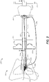
- FIGURES 1 and 2 are side and top views, respectively, of a first embodiment rowing machine 200, with a rower R in at the end of a stroke
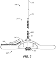
- FIGURE 3 is a top view of a handle 237 and chain 233
- FIGURE 4 is a side view illustrating the chain and a resistance unit 250
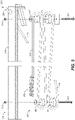
- FIGURE 5 is an exploded view 5-5 of showing one embodiment of a chain return mechanism 232.
- rowing machine 200 includes a frame 210, a resistance unit 250, and power transmission components 230 connecting the frame and resistance unit.
- Frame 210 includes a first portion 211, a second portion 219 and a third portion 221.
- First portion 211 is generally horizontal.
- Second portion 219 is attached to first portion 211 and includes a first end 223 that extends to the ground and a second, forked end 225 attached to an axle 253 of resistance unit 250 and includes legs 213 for supporting the rowing attachment on the ground and a foot support 215 including foot straps 216.
- Third portion 221 is attached to and extends above second portion 219.
- Resistance unit 250 includes a freewheel or freehub assembly including a cassette of gears 251 connected to axle 253 through a one-way clutch that engages with a resistance mechanism (both of which are not shown) within the resistance unit.
- Resistance unit 250 may, for example and without limitation, be generally similar to prior art resistance units of a wheel off bicycle trainer, such as the Tacx NEO (Garmin Ltd, Schaffhausen, Switzerland). Such resistance units provide a force to resist the rotation of the cassette of gears 251 in one direction and provides little force to resist the rotation of the cassette of gears in the opposite direction.
- Resistance unit 250 may include one or more of a flywheel, an air or water resistance mechanism, or a magnetic resistance mechanism that is electronically controllable.
- Resistance unit 250 also includes sensors to measure the power and cadence of the cassette of gears 251, and electronics to accept the sensor measurements, control the resistance to the cassette of gears, and provide information for display on a screen 255.
- Power transmission components 230 include chain 233 coupled to the handle 237 with an attachment ring 301, a first chain guide 241 attached to third frame portion 221, a derailleur 243 attached to second end 225 in a position that is above cassette of gears 251 (as shown in FIG. 4 ), a second chain guide 245 attached to second portion 219, and a chain return mechanism 232.
- Power transmission components 230 also include a gear shifter 247 attached to the handle 237 and a cable 249 connecting the gear shifter and derailleur 243, and a seat 217 including rollers to allow the seat to move along first frame portion 210.
- first portion 211 is angled relative to the horizontal to aid the return of rower and at the end of the stroke.
- derailleur 243 may be an electronic system, such as a Shimano Di2 electric drivetrain (Shimano Inc, Sakai, Japan) or Campagnolo EPS (Campagnolo Vicenza, Italy), or a wireless system, such as SRAM eTap (SRAM, Chicago, IL).
- Shimano Di2 electric drivetrain Shimano Inc, Sakai, Japan
- Campagnolo EPS Campagnolo Vicenza, Italy
- SRAM eTap SRAM, Chicago, IL
- Chain return mechanism 232 is generally contained within second portion 219 and includes an elastic cord 235 coupled to an end of chain 233, rollers 501, 503, 505, and 507 supported on second frame portion 219 by bolts 511 and nuts 513.
- An end 239 of elastic cord 235 is attached to first end 223.
- the handle 237 also includes a mount 303 for a mobile device (not shown).
- the combination of chain 233 and elastic cord 235 referred to herein as a compound cable 231, extends from the handle 237 to first end 223, with chain 233 being guided over first chain guide 241, through derailleur 243, over gears 251, and guided over second chain guide 245.
- Elastic cord 235 extend from chain 233 around rollers 501, 503, 505, and 507 and is attached to frame 210 at first end 223.
- chain return mechanism is a spring loaded cylinder that takes up the slack in chain 233, or a gravity return mechanism (see, for example, US Patent Application Publication No. US20140243163A1 , the content of which are incorporated by reference).
- Resistance unit 250 thus provides a force that counters forces provided by a rower.
- the force provided by resistance unit 250 is transferred from axle 253, to one of gears of gear cassette 251, to chain 233 of compound cable 231, to the handle 237.
- the gear shifter 247 and deraille 243 allow for rower to control the resistance. Slack in chain 233 is taken up by chain return mechanism 232.
- a rowing machine attachment 260 is provided that is connectable to a resistance unit, such as resistance unit 250.
- the rowing machine attachment includes the following components of rowing machine 200 described above: frame 200 adapted for placing on the ground and including a fork end adapted to accept the axle of the resistance unit; seat 217 movable along the frame; a handle 237; chain 233 having a first end attached to the handle and a second end attached to the frame; derailleur 243 attached to the frame; and gear shifter 247 operably connected to the derailleur.
- frame is attached to the axle of the resistance unit, as illustrated in FIG. 1 , and where the chain extends, sequentially, from the handle, through the derailleur, and engages a gear of the plurality of gears, such that the engaged gear is selectable using the gear shifter.
- FIG. 1 is a side view of the first embodiment rowing machine attached to the bicycle trainer resistance unit, with the rower at the beginning of a stroke.
- a tension is provided to chain 233 by resistance unit 250 and while elastic cord 235 takes up any slack in compound cable 231.
- the tension in chain 233 is provided by the force required to rotate gears 251, which may be regulated by the rower using gear shifter 247 to activate derailleur 243 and thus select a gear of gears 251.
- the force required to rotate gears 251 may be adjusted using software in resistance unit 250.
- certain embodiments of resistance unit 250 include sensors to monitor the rotation speed of gears 251 and electronics to determine power expended during rowing.
- resistance unit 250 is in communication with a computer or electronic device, such as a smartphone, which can receive information from resistance unit 250 and which may also provide instructions to the resistance unit to modify the resistance provided by the resistance unit.
- a computer or electronic device such as a smartphone
- the end of stroke is illustrated in FIG. 1 .
- rower R moves forward to the position shown in FIG 6 .
- the one-way clutch permits the chain to move without resistance through resistance unit 250 and return mechanism 232 takes up slack in compound chain 231.
- a rowing machine having a derailleur below the gears provides engagement of the one way-clutch at the beginning of a stroke that is not smooth.
- shifting under load as on an upstroke
- placing the derailleur above the gears, as in FIG. 4 forces the gear shift to happen on a down stroke, when system is not under load and helps to dampen one way-clutch engagement at the beginning of a stroke, resulting in a smoother and more natural motion.
Landscapes
- Health & Medical Sciences (AREA)
- General Health & Medical Sciences (AREA)
- Physical Education & Sports Medicine (AREA)
- Life Sciences & Earth Sciences (AREA)
- Biophysics (AREA)
- Orthopedic Medicine & Surgery (AREA)
- Cardiology (AREA)
- Vascular Medicine (AREA)
- Physics & Mathematics (AREA)
- Electromagnetism (AREA)
- Engineering & Computer Science (AREA)
- Multimedia (AREA)
- Human Computer Interaction (AREA)
- Rehabilitation Tools (AREA)
Abstract
Description
- The present invention generally relates to exercise equipment, and more particularly to rowing machines utilizing gear changing mechanisms.
- Rowing machines are stationary exercise devices that simulate the motion and forces during rowing. Rowing machines generally include a frame having a movable seat and foot rests and a handle that is connected to a resistance unit. During the drive portion of the stroke, the handle pulls on the resistance unit, which provides resistance to the motion of the handle. During the recovery portion of the stoke, there is no resistance to the motion of the handles.
- In certain rowing machines, the handle is connected to the resistance unit through a chain or cord attached to the handle and a mechanism to take up slack of the chain or cord during the stroke. Resistance units for such rowing machines may include one or more of a flywheel, an air or water resistance mechanism, or a magnetic resistance mechanism which provide a resistance force to the pulling of the handle that increases with the speed of the handle. Magnetic resistance mechanisms are electronically controllable, and when used in combination a flywheels and/or an air or water resistance mechanism, can vary the resistance force to the pulling of the handle over a wide range.
- One limitation of rowing machines is that they do not provide an easy way for the rower to adjust the resistance during practice. Thus, while the rowing machine may adjust the resistance through a magnetic resistance mechanism, the rower must work against this resistance and cannot, as in bicycles, for example, shift the resistance mechanism to obtain a larger or smaller resistance during rowing. There is need in the art for an rowing machine that provides the rower with a greater degree of resistance control during rowing. Such a rowing machine should be easy for the rower to operate and should be comprised of standard exercise equipment mechanisms.
- The present invention overcomes some of the disadvantages of prior art by providing a rowing machine connected to a resistance unit by a chain and gear cassette/derailleur configuration in which the chain extends from a handle, through the derailleur, and though the gears. This configuration provides for a smooth operation not found in other systems.
- It is one aspect to provide a rowing machine comprising: a resistance unit including a gear cassette comprising a plurality of gears coupled to a mechanism to resist the rotation of the gear cassette; a frame adapted for placing on the ground and attached to the resistance unit; a seat movable along the frame; a handle; a chain having a first end attached to the handle and a second end attached to the frame; a derailleur attached to the frame; and a gear shifter operably connected to the derailleur. The chain extends, sequentially, from the handle, through the derailleur, and engages a gear of the plurality of gears, such that the engaged gear is selectable using the gear shifter.
- It is another aspect to provide a rowing machine attachment connectable to a resistance unit, where the resistance unit includes an axle and a gear cassette comprising a plurality of gears coupled to a mechanism to resist the rotation of the gear cassette. The rowing machine attachment includes: a frame adapted for placing on the ground and including a fork end adapted to accept the axle of the resistance unit; a seat movable along the frame; a handle; a chain having a first end attached to the handle and a second end attached to the frame; a derailleur attached to the frame; and a gear shifter operably connected to the derailleur. When frame is attached to the axle of the resistance unit and where the chain extends, sequentially, from the handle, through the derailleur, and engages a gear of the plurality of gears, such that the engaged gear is selectable using the gear shifter.
- These features together with the various ancillary provisions and features which will become apparent to those skilled in the art from the following detailed description, are attained by the exercise equipment of the present invention, preferred embodiments thereof being shown with reference to the accompanying drawings, by way of example only, wherein:
-
FIGS. 1 and2 are side and top views, respectively, of a first embodiment rowing machine with the rower at the end of a stroke; -
FIG. 3 is a view of a handle and chain; -
FIG. 4 is a side view illustrating one embodiment of the connection of the chain and resistance unit; -
FIG. 5 is an exploded view 5-5 of showing one embodiment of a chain return mechanism; and -
FIG. 6 is a side view of the first embodiment rowing attachment attached to the bicycle trainer resistance unit, with the rower at the beginning of a stroke. - Reference symbols are used in the Figures to indicate certain components, aspects or features shown therein, with reference symbols common to more than one Figure indicating like components, aspects or features shown therein.
-
FIGURES 1 and2 are side and top views, respectively, of a firstembodiment rowing machine 200, with a rower R in at the end of a stroke,FIGURE 3 is a top view of ahandle 237 andchain 233;FIGURE 4 is a side view illustrating the chain and aresistance unit 250; andFIGURE 5 is an exploded view 5-5 of showing one embodiment of achain return mechanism 232. - As shown in
FIGS. 1 and2 ,rowing machine 200 includes aframe 210, aresistance unit 250, andpower transmission components 230 connecting the frame and resistance unit.Frame 210 includes afirst portion 211, asecond portion 219 and athird portion 221.First portion 211 is generally horizontal.Second portion 219 is attached tofirst portion 211 and includes afirst end 223 that extends to the ground and a second, forkedend 225 attached to anaxle 253 ofresistance unit 250 and includeslegs 213 for supporting the rowing attachment on the ground and afoot support 215 including foot straps 216.Third portion 221 is attached to and extends abovesecond portion 219. -
Resistance unit 250 includes a freewheel or freehub assembly including a cassette ofgears 251 connected toaxle 253 through a one-way clutch that engages with a resistance mechanism (both of which are not shown) within the resistance unit.Resistance unit 250 may, for example and without limitation, be generally similar to prior art resistance units of a wheel off bicycle trainer, such as the Tacx NEO (Garmin Ltd, Schaffhausen, Switzerland). Such resistance units provide a force to resist the rotation of the cassette ofgears 251 in one direction and provides little force to resist the rotation of the cassette of gears in the opposite direction.Resistance unit 250 may include one or more of a flywheel, an air or water resistance mechanism, or a magnetic resistance mechanism that is electronically controllable.Resistance unit 250 also includes sensors to measure the power and cadence of the cassette ofgears 251, and electronics to accept the sensor measurements, control the resistance to the cassette of gears, and provide information for display on ascreen 255. -
Power transmission components 230 includechain 233 coupled to thehandle 237 with anattachment ring 301, afirst chain guide 241 attached tothird frame portion 221, aderailleur 243 attached tosecond end 225 in a position that is above cassette of gears 251 (as shown inFIG. 4 ), asecond chain guide 245 attached tosecond portion 219, and achain return mechanism 232.Power transmission components 230 also include agear shifter 247 attached to thehandle 237 and acable 249 connecting the gear shifter andderailleur 243, and aseat 217 including rollers to allow the seat to move alongfirst frame portion 210. In certain embodiments,first portion 211 is angled relative to the horizontal to aid the return of rower and at the end of the stroke. - In an alternative embodiment,
derailleur 243 may be an electronic system, such as a Shimano Di2 electric drivetrain (Shimano Inc, Sakai, Japan) or Campagnolo EPS (Campagnolo Vicenza, Italy), or a wireless system, such as SRAM eTap (SRAM, Chicago, IL). -
Chain return mechanism 232, shown inFIGS. 3 and5 , is generally contained withinsecond portion 219 and includes anelastic cord 235 coupled to an end ofchain 233,rollers second frame portion 219 bybolts 511 and nuts 513. Anend 239 ofelastic cord 235 is attached tofirst end 223. Thehandle 237 also includes amount 303 for a mobile device (not shown). The combination ofchain 233 andelastic cord 235, referred to herein as acompound cable 231, extends from thehandle 237 tofirst end 223, withchain 233 being guided overfirst chain guide 241, throughderailleur 243, overgears 251, and guided oversecond chain guide 245.Elastic cord 235 extend fromchain 233 aroundrollers first end 223. - In an alternative embodiment,
chain return mechanism 232 includes an elastic cord that pulls on an end ofchain 233 as provided, for example and without limitation, by the Concept2 skewer assembly (Morrisville, Vermont) (see, for example, https://shop.concept2.com/ model-b/249-skewer-assembly. html?search_query=skewer+assembly&results=6). In another alternative embodiment, chain return mechanism is a spring loaded cylinder that takes up the slack inchain 233, or a gravity return mechanism (see, for example, US Patent Application Publication No.US20140243163A1 , the content of which are incorporated by reference). -
Resistance unit 250 thus provides a force that counters forces provided by a rower. The force provided byresistance unit 250 is transferred fromaxle 253, to one of gears ofgear cassette 251, tochain 233 ofcompound cable 231, to thehandle 237. In addition to resistance due to a flywheel or an electromagnetic or other mechanism for controlling the resistance, thegear shifter 247 andderailleurs 243 allow for rower to control the resistance. Slack inchain 233 is taken up bychain return mechanism 232. - In another embodiment, a
rowing machine attachment 260 is provided that is connectable to a resistance unit, such asresistance unit 250. The rowing machine attachment includes the following components ofrowing machine 200 described above: frame 200 adapted for placing on the ground and including a fork end adapted to accept the axle of the resistance unit;seat 217 movable along the frame; ahandle 237;chain 233 having a first end attached to the handle and a second end attached to the frame;derailleur 243 attached to the frame; andgear shifter 247 operably connected to the derailleur. When frame is attached to the axle of the resistance unit, as illustrated inFIG. 1 , and where the chain extends, sequentially, from the handle, through the derailleur, and engages a gear of the plurality of gears, such that the engaged gear is selectable using the gear shifter. - One use of
rowing machine 200 and of arowing machine attachment 260 connected toresistance unit 250 is illustrated with reference toFIG. 1 and withFIGURE 6 , which is a side view of the first embodiment rowing machine attached to the bicycle trainer resistance unit, with the rower at the beginning of a stroke. - At the beginning of a stroke, as shown in
FIG. 6 , the arms of rower R are fully extended,seat 217 is in a forward position, andelastic cord 235 retractscompound cable 231 towardsfirst end 223. Rower R then pulls on thehandle 237 towards their body while pushing their feet againstfoot support 215 and extending their legs. Bothseat 217 and thehandle 237 then move backwards, withchain 233 being pulled through theresistance unit 250 and withelastic cord 235 elongating. During astroke resistance unit 250 provides a resistance simulating the force during rowing. - During a stoke, as the
handle 237 is pulled backwards and away fromresistance unit 250, a tension is provided to chain 233 byresistance unit 250 and whileelastic cord 235 takes up any slack incompound cable 231. The tension inchain 233 is provided by the force required to rotategears 251, which may be regulated by the rower usinggear shifter 247 to activatederailleur 243 and thus select a gear ofgears 251. Alternatively, or in combination withgear shifter 247, the force required to rotategears 251 may be adjusted using software inresistance unit 250. Thus, for example, certain embodiments ofresistance unit 250 include sensors to monitor the rotation speed ofgears 251 and electronics to determine power expended during rowing. In certain other embodiments,resistance unit 250 is in communication with a computer or electronic device, such as a smartphone, which can receive information fromresistance unit 250 and which may also provide instructions to the resistance unit to modify the resistance provided by the resistance unit. The end of stroke is illustrated inFIG. 1 . - After the end of the stroke, rower R moves forward to the position shown in
FIG 6 . The one-way clutch permits the chain to move without resistance throughresistance unit 250 andreturn mechanism 232 takes up slack incompound chain 231. - The inventor found that a rowing machine having a derailleur below the gears, as is generally provided on bicycles or bicycle trainers provides engagement of the one way-clutch at the beginning of a stroke that is not smooth. Thus, for example, shifting under load, as on an upstroke, can be painful for the rower. In contrast, placing the derailleur above the gears, as in
FIG. 4 forces the gear shift to happen on a down stroke, when system is not under load and helps to dampen one way-clutch engagement at the beginning of a stroke, resulting in a smoother and more natural motion. - Reference throughout this specification to "one embodiment" or "an embodiment" means that a particular feature, structure, or characteristic described in connection with the embodiment is included in at least one embodiment of the present invention. Thus, appearances of the phrases "in one embodiment" or "in an embodiment" in various places throughout this specification are not necessarily all referring to the same embodiment. Furthermore, the particular features, structures or characteristics may be combined in any suitable manner, as would be apparent to one of ordinary skill in the art from this disclosure, in one or more embodiments.
- Similarly, it should be appreciated that in the above description of exemplary embodiments of the invention, various features of the invention are sometimes grouped together in a single embodiment, figure, or description thereof for the purpose of streamlining the disclosure and aiding in the understanding of one or more of the various inventive aspects. This method of disclosure, however, is not to be interpreted as reflecting an intention that the claimed invention requires more features than are expressly recited in each claim. Rather, as the following claims reflect, inventive aspects lie in less than all features of a single foregoing disclosed embodiment. Thus, the claims following the Detailed Description are hereby expressly incorporated into this Detailed Description, with each claim standing on its own as a separate embodiment of this invention.
- Thus, while there has been described what is believed to be the preferred embodiments of the invention, those skilled in the art will recognize that other and further modifications may be made thereto without departing from the spirit of the invention, and it is intended to claim all such changes and modifications as fall within the scope of the invention. Steps may be added or deleted to methods described within the scope of the present invention.
Claims (14)
- A rowing machine attachment connectable to a resistance unit, where the resistance unit includes an axle and a gear cassette comprising a plurality of gears coupled to a mechanism to resist the rotation of the gear cassette, said rowing machine attachment comprising:a frame adapted for placing on the ground and including a fork end adapted to accept the axle of the resistance unit;a seat movable along the frame;a handle;a chain having a first end attached to the handle and a second end attached to the frame;a derailleur attached to the frame; anda gear shifter operably connected to the derailleur,where, when the fork end of the frame is attached to the axle of the resistance unit and where the chain extends, sequentially, from the handle, through the derailleur, and engages a gear of the plurality of gears,such that the engaged gear is selectable using the gear shifter.
- The rowing machine attachment of claim 1, where the resistance unit is an off-wheel bicycle trainer resistance unit.
- The rowing machine attachment of claim 1 or 2, where the mechanism to resist the rotation of the gears includes a one-way clutch connecting the mechanism to the gear cassette.
- The rowing machine attachment of any of claims 1 to 3, where the mechanism to resist the rotation of the gears includes a flywheel.
- The rowing machine attachment of any of claims 1 to 4, where the mechanism to resist the rotation of the gears includes an electromagnet.
- The rowing machine attachment of any of claims 1 to 5, where the rowing machine includes a return mechanism disposed between the second end of the chain and the frame.
- The rowing machine attachment of claim 6, where the return mechanism includes an elastic cord.
- A rowing machine comprising:a resistance unit including a gear cassette comprising a plurality of gears coupled to a mechanism to resist the rotation of the gear cassette;a frame adapted for placing on the ground and attached to the resistance unit;a seat movable along the frame;a handle;a chain having a first end attached to the handle and a second end attached to the frame;a derailleur attached to the frame; anda gear shifter operably connected to the derailleur,where the chain extends, sequentially, from the handle, through the derailleur, and engages a gear of the plurality of gears,such that the engaged gear is selectable using the gear shifter.
- The rowing machine of claim 8, where the resistance unit is an off-wheel bicycle trainer resistance unit.
- The rowing machine of claim 8 or 9, where the mechanism to resist the rotation of the gears includes a one-way clutch connecting the mechanism to the gear cassette.
- The rowing machine of any of claims 8 to 10, where the mechanism to resist the rotation of the gears includes a flywheel.
- The rowing machine of any of claims 8 to 11, where the mechanism to resist the rotation of the gears includes an electromagnet.
- The rowing machine of any of claims 8 to 12, where the rowing machine includes a return mechanism disposed between the second end of the chain and the frame.
- The rowing machine of claim 13, where the return mechanism includes an elastic cord.
Applications Claiming Priority (1)
| Application Number | Priority Date | Filing Date | Title |
|---|---|---|---|
| US17/319,016 US20220362623A1 (en) | 2021-05-12 | 2021-05-12 | Rowing machine including a gear shift mechanism |
Publications (1)
| Publication Number | Publication Date |
|---|---|
| EP4088788A1 true EP4088788A1 (en) | 2022-11-16 |
Family
ID=81648552
Family Applications (1)
| Application Number | Title | Priority Date | Filing Date |
|---|---|---|---|
| EP22172936.1A Withdrawn EP4088788A1 (en) | 2021-05-12 | 2022-05-12 | Rowing machine including a gear shift mechanism |
Country Status (4)
| Country | Link |
|---|---|
| US (1) | US20220362623A1 (en) |
| EP (1) | EP4088788A1 (en) |
| AU (1) | AU2022203137A1 (en) |
| CA (1) | CA3160335A1 (en) |
Families Citing this family (3)
| Publication number | Priority date | Publication date | Assignee | Title |
|---|---|---|---|---|
| CN115721917A (en) * | 2022-11-25 | 2023-03-03 | 杭州英吉士电机有限公司 | A loading motor of a rowing machine |
| US20250144462A1 (en) * | 2023-11-07 | 2025-05-08 | Paul S. Pflum | Compact exercise apparatus |
| IL315915A (en) | 2024-09-25 | 2026-04-01 | Raz Malchi | Modular training system |
Citations (5)
| Publication number | Priority date | Publication date | Assignee | Title |
|---|---|---|---|---|
| US4396188A (en) * | 1981-07-15 | 1983-08-02 | Dreissigacker Peter D | Stationary rowing unit |
| CA1183559A (en) * | 1983-11-25 | 1985-03-05 | Michael Terpenning | Rowing ergometer |
| US4772013A (en) * | 1985-12-09 | 1988-09-20 | Tarlow Jr Elliot S | Rowing exercise machine |
| US20140243163A1 (en) | 2013-02-26 | 2014-08-28 | Robert Edmondson | Gravity return rowing exercise device |
| EP3357544A1 (en) * | 2017-02-02 | 2018-08-08 | RP3 Rowing B.V. | Exercise device |
Family Cites Families (13)
| Publication number | Priority date | Publication date | Assignee | Title |
|---|---|---|---|---|
| US4886287A (en) * | 1988-03-15 | 1989-12-12 | Jack Cherubini | Row bar-actuated land vehicle |
| US4928986A (en) * | 1988-05-06 | 1990-05-29 | P. D. Enterprises, Inc. | Arm and leg powered cycle |
| US5833256A (en) * | 1995-11-20 | 1998-11-10 | Gilmore; Roger C. | User powered vehicle and propulsion mechanism |
| US6588786B2 (en) * | 2001-08-24 | 2003-07-08 | Darrold Efflandt, Sr. | Chain driven front wheel drive and rear wheel steering bicycle |
| US7753386B2 (en) * | 2002-03-20 | 2010-07-13 | Robert Drymalski | Steering mechanism and method for a manually powered vehicle |
| JP4145836B2 (en) * | 2004-06-15 | 2008-09-03 | 株式会社シマノ | Bicycle shift drive |
| US7237786B2 (en) * | 2004-08-19 | 2007-07-03 | Iaz's Custom Welding, Inc. | Rowing bicycle |
| WO2008157439A1 (en) * | 2007-06-13 | 2008-12-24 | Reyes Rodolfo Rudy | Systems and methods for a front wheel drive bicycle |
| US7946963B1 (en) * | 2008-02-12 | 2011-05-24 | Josef Schreiner | Exercise cycle |
| US20160279464A1 (en) * | 2015-03-26 | 2016-09-29 | Kuo-Lung Liu | Exercise device for rowing motion simulation |
| ITUA20163168A1 (en) * | 2016-05-05 | 2017-11-05 | Technogym Spa | Perfected rower. |
| US10279214B2 (en) * | 2017-08-21 | 2019-05-07 | Johnson Health Tech Co., Ltd. | Exercise apparatus |
| US10752317B1 (en) * | 2018-07-03 | 2020-08-25 | Bill B. Jones | Leg and arm powered vehicle |
-
2021
- 2021-05-12 US US17/319,016 patent/US20220362623A1/en not_active Abandoned
-
2022
- 2022-05-11 AU AU2022203137A patent/AU2022203137A1/en not_active Abandoned
- 2022-05-11 CA CA3160335A patent/CA3160335A1/en active Pending
- 2022-05-12 EP EP22172936.1A patent/EP4088788A1/en not_active Withdrawn
Patent Citations (5)
| Publication number | Priority date | Publication date | Assignee | Title |
|---|---|---|---|---|
| US4396188A (en) * | 1981-07-15 | 1983-08-02 | Dreissigacker Peter D | Stationary rowing unit |
| CA1183559A (en) * | 1983-11-25 | 1985-03-05 | Michael Terpenning | Rowing ergometer |
| US4772013A (en) * | 1985-12-09 | 1988-09-20 | Tarlow Jr Elliot S | Rowing exercise machine |
| US20140243163A1 (en) | 2013-02-26 | 2014-08-28 | Robert Edmondson | Gravity return rowing exercise device |
| EP3357544A1 (en) * | 2017-02-02 | 2018-08-08 | RP3 Rowing B.V. | Exercise device |
Also Published As
| Publication number | Publication date |
|---|---|
| US20220362623A1 (en) | 2022-11-17 |
| AU2022203137A1 (en) | 2022-12-01 |
| CA3160335A1 (en) | 2022-11-12 |
Similar Documents
| Publication | Publication Date | Title |
|---|---|---|
| EP4088788A1 (en) | Rowing machine including a gear shift mechanism | |
| US8333681B2 (en) | Speed controlled strength machine | |
| US7641597B2 (en) | Dynamic isokinetic exercise apparatus | |
| US10874893B2 (en) | Hybrid resistance system | |
| EP2326393B1 (en) | Continuous rope pulling exercise apparatus | |
| US5199931A (en) | Exercise machine for simulating stair climbing | |
| US10279214B2 (en) | Exercise apparatus | |
| US6302829B1 (en) | Speed-control exercise method and apparatus | |
| US8409059B2 (en) | Power assisted arm driven treadmill | |
| US4928986A (en) | Arm and leg powered cycle | |
| US8562495B2 (en) | Upper body exercise apparatus for stationary bike | |
| CN101484350A (en) | Continuously variable drivetrain | |
| US6695332B1 (en) | Bicycle transmission device for unidirectional output from bi-directional input | |
| US5871221A (en) | Driving apparatus for bicycles and the like | |
| US7267639B2 (en) | Compound bicycle exercising device | |
| CN201424108Y (en) | rowing bicycle | |
| EP0768233A2 (en) | A cycle | |
| CN101870329B (en) | rowing bicycle | |
| US7303202B1 (en) | Apparatus for the transfer of linear human power to a rotating member | |
| RU133500U1 (en) | KICK SCOOTER | |
| WO2007056837A1 (en) | Power pedal for a bicycle | |
| EP1700621A1 (en) | Compound bicycle exercising device |
Legal Events
| Date | Code | Title | Description |
|---|---|---|---|
| PUAI | Public reference made under article 153(3) epc to a published international application that has entered the european phase |
Free format text: ORIGINAL CODE: 0009012 |
|
| STAA | Information on the status of an ep patent application or granted ep patent |
Free format text: STATUS: THE APPLICATION HAS BEEN PUBLISHED |
|
| AK | Designated contracting states |
Kind code of ref document: A1 Designated state(s): AL AT BE BG CH CY CZ DE DK EE ES FI FR GB GR HR HU IE IS IT LI LT LU LV MC MK MT NL NO PL PT RO RS SE SI SK SM TR |
|
| STAA | Information on the status of an ep patent application or granted ep patent |
Free format text: STATUS: REQUEST FOR EXAMINATION WAS MADE |
|
| 17P | Request for examination filed |
Effective date: 20230516 |
|
| RBV | Designated contracting states (corrected) |
Designated state(s): AL AT BE BG CH CY CZ DE DK EE ES FI FR GB GR HR HU IE IS IT LI LT LU LV MC MK MT NL NO PL PT RO RS SE SI SK SM TR |
|
| STAA | Information on the status of an ep patent application or granted ep patent |
Free format text: STATUS: THE APPLICATION IS DEEMED TO BE WITHDRAWN |
|
| 18D | Application deemed to be withdrawn |
Effective date: 20241203 |