EP4088764B1 - Medikamenteninjektionsgerät - Google Patents
Medikamenteninjektionsgerät Download PDFInfo
- Publication number
- EP4088764B1 EP4088764B1 EP22172246.5A EP22172246A EP4088764B1 EP 4088764 B1 EP4088764 B1 EP 4088764B1 EP 22172246 A EP22172246 A EP 22172246A EP 4088764 B1 EP4088764 B1 EP 4088764B1
- Authority
- EP
- European Patent Office
- Prior art keywords
- drug
- dose
- rack
- dose setting
- injection device
- Prior art date
- Legal status (The legal status is an assumption and is not a legal conclusion. Google has not performed a legal analysis and makes no representation as to the accuracy of the status listed.)
- Active
Links
Images


Classifications
-
- A—HUMAN NECESSITIES
- A61—MEDICAL OR VETERINARY SCIENCE; HYGIENE
- A61M—DEVICES FOR INTRODUCING MEDIA INTO, OR ONTO, THE BODY; DEVICES FOR TRANSDUCING BODY MEDIA OR FOR TAKING MEDIA FROM THE BODY; DEVICES FOR PRODUCING OR ENDING SLEEP OR STUPOR
- A61M5/00—Devices for bringing media into the body in a subcutaneous, intra-vascular or intramuscular way; Accessories therefor, e.g. filling or cleaning devices, arm-rests
- A61M5/178—Syringes
- A61M5/24—Ampoule syringes, i.e. syringes with needle for use in combination with replaceable ampoules or carpules, e.g. automatic
-
- A—HUMAN NECESSITIES
- A61—MEDICAL OR VETERINARY SCIENCE; HYGIENE
- A61M—DEVICES FOR INTRODUCING MEDIA INTO, OR ONTO, THE BODY; DEVICES FOR TRANSDUCING BODY MEDIA OR FOR TAKING MEDIA FROM THE BODY; DEVICES FOR PRODUCING OR ENDING SLEEP OR STUPOR
- A61M5/00—Devices for bringing media into the body in a subcutaneous, intra-vascular or intramuscular way; Accessories therefor, e.g. filling or cleaning devices, arm-rests
- A61M5/178—Syringes
- A61M5/31—Details
- A61M5/3129—Syringe barrels
-
- A—HUMAN NECESSITIES
- A61—MEDICAL OR VETERINARY SCIENCE; HYGIENE
- A61M—DEVICES FOR INTRODUCING MEDIA INTO, OR ONTO, THE BODY; DEVICES FOR TRANSDUCING BODY MEDIA OR FOR TAKING MEDIA FROM THE BODY; DEVICES FOR PRODUCING OR ENDING SLEEP OR STUPOR
- A61M5/00—Devices for bringing media into the body in a subcutaneous, intra-vascular or intramuscular way; Accessories therefor, e.g. filling or cleaning devices, arm-rests
- A61M5/178—Syringes
- A61M5/31—Details
- A61M5/315—Pistons; Piston-rods; Guiding, blocking or restricting the movement of the rod or piston; Appliances on the rod for facilitating dosing ; Dosing mechanisms
- A61M5/31501—Means for blocking or restricting the movement of the rod or piston
-
- A—HUMAN NECESSITIES
- A61—MEDICAL OR VETERINARY SCIENCE; HYGIENE
- A61M—DEVICES FOR INTRODUCING MEDIA INTO, OR ONTO, THE BODY; DEVICES FOR TRANSDUCING BODY MEDIA OR FOR TAKING MEDIA FROM THE BODY; DEVICES FOR PRODUCING OR ENDING SLEEP OR STUPOR
- A61M5/00—Devices for bringing media into the body in a subcutaneous, intra-vascular or intramuscular way; Accessories therefor, e.g. filling or cleaning devices, arm-rests
- A61M5/178—Syringes
- A61M5/31—Details
- A61M5/315—Pistons; Piston-rods; Guiding, blocking or restricting the movement of the rod or piston; Appliances on the rod for facilitating dosing ; Dosing mechanisms
- A61M5/31511—Piston or piston-rod constructions, e.g. connection of piston with piston-rod
-
- A—HUMAN NECESSITIES
- A61—MEDICAL OR VETERINARY SCIENCE; HYGIENE
- A61M—DEVICES FOR INTRODUCING MEDIA INTO, OR ONTO, THE BODY; DEVICES FOR TRANSDUCING BODY MEDIA OR FOR TAKING MEDIA FROM THE BODY; DEVICES FOR PRODUCING OR ENDING SLEEP OR STUPOR
- A61M5/00—Devices for bringing media into the body in a subcutaneous, intra-vascular or intramuscular way; Accessories therefor, e.g. filling or cleaning devices, arm-rests
- A61M5/178—Syringes
- A61M5/31—Details
- A61M5/315—Pistons; Piston-rods; Guiding, blocking or restricting the movement of the rod or piston; Appliances on the rod for facilitating dosing ; Dosing mechanisms
- A61M5/31533—Dosing mechanisms, i.e. setting a dose
- A61M5/31535—Means improving security or handling thereof, e.g. blocking means, means preventing insufficient dosing, means allowing correction of overset dose
- A61M5/31541—Means preventing setting of a dose beyond the amount remaining in the cartridge
-
- A—HUMAN NECESSITIES
- A61—MEDICAL OR VETERINARY SCIENCE; HYGIENE
- A61M—DEVICES FOR INTRODUCING MEDIA INTO, OR ONTO, THE BODY; DEVICES FOR TRANSDUCING BODY MEDIA OR FOR TAKING MEDIA FROM THE BODY; DEVICES FOR PRODUCING OR ENDING SLEEP OR STUPOR
- A61M5/00—Devices for bringing media into the body in a subcutaneous, intra-vascular or intramuscular way; Accessories therefor, e.g. filling or cleaning devices, arm-rests
- A61M5/178—Syringes
- A61M5/31—Details
- A61M5/315—Pistons; Piston-rods; Guiding, blocking or restricting the movement of the rod or piston; Appliances on the rod for facilitating dosing ; Dosing mechanisms
- A61M5/31533—Dosing mechanisms, i.e. setting a dose
- A61M5/31545—Setting modes for dosing
- A61M5/31548—Mechanically operated dose setting member
- A61M5/3155—Mechanically operated dose setting member by rotational movement of dose setting member, e.g. during setting or filling of a syringe
- A61M5/31551—Mechanically operated dose setting member by rotational movement of dose setting member, e.g. during setting or filling of a syringe including axial movement of dose setting member
-
- A—HUMAN NECESSITIES
- A61—MEDICAL OR VETERINARY SCIENCE; HYGIENE
- A61M—DEVICES FOR INTRODUCING MEDIA INTO, OR ONTO, THE BODY; DEVICES FOR TRANSDUCING BODY MEDIA OR FOR TAKING MEDIA FROM THE BODY; DEVICES FOR PRODUCING OR ENDING SLEEP OR STUPOR
- A61M5/00—Devices for bringing media into the body in a subcutaneous, intra-vascular or intramuscular way; Accessories therefor, e.g. filling or cleaning devices, arm-rests
- A61M5/178—Syringes
- A61M5/31—Details
- A61M5/315—Pistons; Piston-rods; Guiding, blocking or restricting the movement of the rod or piston; Appliances on the rod for facilitating dosing ; Dosing mechanisms
- A61M5/31533—Dosing mechanisms, i.e. setting a dose
- A61M5/31545—Setting modes for dosing
- A61M5/31548—Mechanically operated dose setting member
- A61M5/3155—Mechanically operated dose setting member by rotational movement of dose setting member, e.g. during setting or filling of a syringe
- A61M5/31553—Mechanically operated dose setting member by rotational movement of dose setting member, e.g. during setting or filling of a syringe without axial movement of dose setting member
-
- A—HUMAN NECESSITIES
- A61—MEDICAL OR VETERINARY SCIENCE; HYGIENE
- A61M—DEVICES FOR INTRODUCING MEDIA INTO, OR ONTO, THE BODY; DEVICES FOR TRANSDUCING BODY MEDIA OR FOR TAKING MEDIA FROM THE BODY; DEVICES FOR PRODUCING OR ENDING SLEEP OR STUPOR
- A61M5/00—Devices for bringing media into the body in a subcutaneous, intra-vascular or intramuscular way; Accessories therefor, e.g. filling or cleaning devices, arm-rests
- A61M5/178—Syringes
- A61M5/31—Details
- A61M5/315—Pistons; Piston-rods; Guiding, blocking or restricting the movement of the rod or piston; Appliances on the rod for facilitating dosing ; Dosing mechanisms
- A61M5/31533—Dosing mechanisms, i.e. setting a dose
- A61M5/31545—Setting modes for dosing
- A61M5/31548—Mechanically operated dose setting member
- A61M5/31561—Mechanically operated dose setting member using freely adjustable volume steps
-
- A—HUMAN NECESSITIES
- A61—MEDICAL OR VETERINARY SCIENCE; HYGIENE
- A61M—DEVICES FOR INTRODUCING MEDIA INTO, OR ONTO, THE BODY; DEVICES FOR TRANSDUCING BODY MEDIA OR FOR TAKING MEDIA FROM THE BODY; DEVICES FOR PRODUCING OR ENDING SLEEP OR STUPOR
- A61M5/00—Devices for bringing media into the body in a subcutaneous, intra-vascular or intramuscular way; Accessories therefor, e.g. filling or cleaning devices, arm-rests
- A61M5/178—Syringes
- A61M5/31—Details
- A61M5/315—Pistons; Piston-rods; Guiding, blocking or restricting the movement of the rod or piston; Appliances on the rod for facilitating dosing ; Dosing mechanisms
- A61M5/31533—Dosing mechanisms, i.e. setting a dose
- A61M5/31545—Setting modes for dosing
- A61M5/31548—Mechanically operated dose setting member
- A61M5/31563—Mechanically operated dose setting member interacting with a displaceable stop member
-
- A—HUMAN NECESSITIES
- A61—MEDICAL OR VETERINARY SCIENCE; HYGIENE
- A61M—DEVICES FOR INTRODUCING MEDIA INTO, OR ONTO, THE BODY; DEVICES FOR TRANSDUCING BODY MEDIA OR FOR TAKING MEDIA FROM THE BODY; DEVICES FOR PRODUCING OR ENDING SLEEP OR STUPOR
- A61M5/00—Devices for bringing media into the body in a subcutaneous, intra-vascular or intramuscular way; Accessories therefor, e.g. filling or cleaning devices, arm-rests
- A61M5/178—Syringes
- A61M5/31—Details
- A61M5/315—Pistons; Piston-rods; Guiding, blocking or restricting the movement of the rod or piston; Appliances on the rod for facilitating dosing ; Dosing mechanisms
- A61M5/31565—Administration mechanisms, i.e. constructional features, modes of administering a dose
- A61M5/31576—Constructional features or modes of drive mechanisms for piston rods
- A61M5/31578—Constructional features or modes of drive mechanisms for piston rods based on axial translation, i.e. components directly operatively associated and axially moved with plunger rod
- A61M5/3158—Constructional features or modes of drive mechanisms for piston rods based on axial translation, i.e. components directly operatively associated and axially moved with plunger rod performed by axially moving actuator operated by user, e.g. an injection button
-
- A—HUMAN NECESSITIES
- A61—MEDICAL OR VETERINARY SCIENCE; HYGIENE
- A61M—DEVICES FOR INTRODUCING MEDIA INTO, OR ONTO, THE BODY; DEVICES FOR TRANSDUCING BODY MEDIA OR FOR TAKING MEDIA FROM THE BODY; DEVICES FOR PRODUCING OR ENDING SLEEP OR STUPOR
- A61M5/00—Devices for bringing media into the body in a subcutaneous, intra-vascular or intramuscular way; Accessories therefor, e.g. filling or cleaning devices, arm-rests
- A61M5/178—Syringes
- A61M5/31—Details
- A61M5/315—Pistons; Piston-rods; Guiding, blocking or restricting the movement of the rod or piston; Appliances on the rod for facilitating dosing ; Dosing mechanisms
- A61M5/31565—Administration mechanisms, i.e. constructional features, modes of administering a dose
- A61M5/3159—Dose expelling manners
- A61M5/31593—Multi-dose, i.e. individually set dose repeatedly administered from the same medicament reservoir
-
- A—HUMAN NECESSITIES
- A61—MEDICAL OR VETERINARY SCIENCE; HYGIENE
- A61M—DEVICES FOR INTRODUCING MEDIA INTO, OR ONTO, THE BODY; DEVICES FOR TRANSDUCING BODY MEDIA OR FOR TAKING MEDIA FROM THE BODY; DEVICES FOR PRODUCING OR ENDING SLEEP OR STUPOR
- A61M2205/00—General characteristics of the apparatus
- A61M2205/27—General characteristics of the apparatus preventing use
Definitions
- the present invention relates to a drug injection device.
- US 10569024B2 , US 2012/0283648A1 and US 2019/0366007A1 disclose drug injection devices which, in addition to comprising members configured to allow the user to set a desired dose before delivering such a dose, further comprise members configured to prevent the user to set a dose exceeding the dose volume remaining in the cartridge after having delivered one or more doses.
- the term “axial” and the corresponding term “axially” are used to refer to a longitudinal direction of the injection device, which corresponds to the longitudinal direction of the cartridge housing, whereas the term “radial” and the corresponding term “radially” are used to refer to a any direction perpendicular to the abovementioned longitudinal direction.
- the terms “radial” and radially” are used to indicate any direction perpendicular to such an axis.
- a longitudinal direction oriented from the hand of the user who handles the injection device during the injection operation toward the injection site is herein also referred to with the term "distal direction”, whereas a longitudinal direction oriented from the injection site toward the hand of the user who handles the injection device during the injection operation is herein also referred to with the term "proximal direction”.
- correlated is used to indicate a mutual dependency relationship between two parameters, like for example two linear dimensions or a linear dimension and a volume. This means that the amount or size or extent of a first parameter is a function of (or depends on) the amount or size or extent of a second parameter and/or vice versa.
- the Applicant has perceived that the provision in the drug injection device of a pinion-rack coupling wherein, during each dose setting operation, the pinion is prevented to move axially with respect to the dose setting service element while being driven in rotation by the dose setting service element and the rack moves with respect to the cartridge housing due to the engagement with the pinion causes, during the first dose setting operation and any further dose setting operation subsequent to the first dose delivery operation, for the rack to travel a corresponding partial axial length which depends on the specific dose actually set and delivered each time, so that from the first dose setting and delivery operation to the last dose setting and delivery operation the rack travels a total axial length which depends on the maximum dispensable drug volume provided within the cartridge.
- the Applicant has though that the provision in the pinion and in the rack of respective abutment elements configured to abut with each other when the rack has travelled the abovementioned total axial length obstruct a further rotation of the pinion (and therefore of the dose setting service element) after having reached, during any further dose setting operation subsequent to the first dose delivery operation, a dose equal to the dose volume currently present in the cartridge, thus preventing the user to set a dose greater than the one still available.
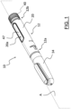
- the injection device is of the pen-type, so as to allow an easy portability, handling, storing and operation of the injection device by the user.
- the injection device of the invention is compact irrespective of the provision of the last dose setting device.
- the size of the injection device can be the same as that of the injection devices of DE 202012001411U1 and US 8512296B2 , which do not include any last dose setting devices.
- the injection device can be of the re-usable or disposable type, whereas the disposable use is the most preferred one.
- the dose setting service element does not move along said longitudinal direction.
- the dose setting service element is configured to move along said longitudinal direction toward the cartridge housing (thus along the distal direction) during the drug dose delivery.
- the dose setting mechanism and the dose delivery mechanism share a same structural element (namely, the dose setting service element), to the benefit of the compactness of the injection device.
- the dose setting service element does not rotate about said longitudinal axis.
- the rotational movement of the dose setting service element only during the dose setting operation and the axial movement of the dose setting service element only during the dose delivery operation allow these two operations to be structurally and functionally separate from each other while sharing a same structural element, namely the dose setting service element.
- the rack has a predetermined axial dimension which is correlated to an axial length travelled by the dose setting service element for delivering the predetermined drug volume.
- This specific provision allows to select the specific axial dimension of the rack depending on the specific drug volume contained in the cartridge to be used, thus ensuring an identical effective operation of the injection device when new cartridges having the same volume of drug are used.
- the pinion is located at a first free end of the rack closer to the cartridge housing.
- the pinion is located at a second free end of the rack opposite to said first free end of the rack.
- the axial length travelled by the rack from the first dose setting and delivery operation to the last dose setting and delivery operation is equal to the axial dimension of the rack.
- said mutual abutment elements comprise a first rotational end stop element associated with the pinion.
- said mutual abutment elements comprise a second rotational end stop element associated with the rack.
- the provision of rotational end stop elements allows an effective stop to the rotation of the pinion and, accordingly, to the axial movement of the rack during the last dose setting operation.
- the dose setting service element has at least one planar surface and the pinion has at least one planar profile portion coupled to the at least one planar surface of the dose setting service element.
- This allows an effective rotational coupling between pinion and dose setting service element during the dose setting operation as well as an effective sliding coupling between pinion and dose setting service element during the dose delivery operation.
- a cartridge housing 16 extending coaxially with the longitudinal axis X is removably coupled to the main body 12 at the first free end 12a so as to be housed within the cap case 14 when the latter is coupled to the main body 12.
- the cartridge housing 16 is configured to house a cartridge 17 including a predetermined drug volume to be delivered.
- the main body 12 comprises an outer case 20, which preferably is substantially cylindrically-shaped.
- dose setting mechanism 30 and dose delivery mechanism 35 can be foreseen in the injection device 10 of the invention, they are not described in detail herein.
- the dose setting mechanism 30 and dose delivery mechanism 35 can be of the same type as described in DE 202012001411U1 and US 8512296B2 .
- the dose delivery mechanism 30 of the injection device 10 differs from the one of the devices of these two prior art documents in that it further includes a last dose setting device 60, shown in figure 2 and described in more details below with reference to figures 3-6 .
- the dose setting mechanism 30 and the dose delivery mechanism 35 share a knob 40 provided at a second free end 12b of the main body 12 opposite the first free end 12a thereof and a dose setting service element arranged within the outer case 20 coaxially to the longitudinal axis X and having a free end operatively connected to the knob 40.
- the abovementioned dose setting service element is a piston rod 44 extending coaxially to the longitudinal axis X.
- the knob 40 is configured to be driven by the user in rotation clockwise and counterclockwise about the longitudinal axis X to drive the dose setting mechanism 30 and to be pushed by the user along a longitudinal (or distal) direction P parallel to the longitudinal axis X to drive the dose delivery mechanism 35.
- the piston rod 44 rotates about the longitudinal axis X and is prevented to move along the longitudinal direction P, whereas in the dose delivery configuration the piston rod 44 moves along the longitudinal direction P and is prevented to rotate about the longitudinal axis X.
- the piston rod 44 is coupled to a dose setting sleeve 46 which rotates about the longitudinal axis X both in the dose setting configuration and in the dose delivery configuration.
- a dose setting sleeve 46 which rotates about the longitudinal axis X both in the dose setting configuration and in the dose delivery configuration.
- the rotation of the dose setting sleeve 46 and of the piston rod 44 is driven by the clutch device 50 which in turn is driven by the rotation of the knob 40 about the longitudinal axis X, whereas in the dose delivery configuration the rotation of the dose setting sleeve 46 is caused by an axial thrust exerted by the user on the knob 40 along the longitudinal direction P.
- the dose setting sleeve 46 comprises an outer surface 47 (shown in figure 1 ) having a plurality of numbers (or generally indicia, not shown), each number being correlated to a respective dose of all the settable doses.
- a display window 20a is formed in the outer case 20.
- the user rotates the knob 40 clockwise or counterclockwise till the number correlated to the desired dose to be set and delivered is displayed through at the display window 20a, thus providing the user with a visual indication about the dose actually set.
- Rotation in both directions during the dose setting operation allows the user to set the desired dose in case he/she initially sets a dose greater or lower than the desired dose.
- the user pushes the knob 40 along the longitudinal direction P to deliver such a dose.
- the axial movement of the knob 40 causes the clutch device 50 to switch the injection device 10 from the dose setting configuration to the dose delivery configuration. In the latter configuration the knob 40 is prevented to rotate.
- a stopper 55 (shown in figure 2 ) is coupled to the free end of the piston rod 44 opposite to the knob 40.
- the stopper 55 is initially inserted within the cartridge 17, provided within the cartridge housing 16, at a free end of the cartridge 17 located at the free end 12a of the main body 12. Due to the axial movement of the piston rod 44 caused by the axial movement of the knob 40 during the dose delivery operation, the stopper 55 axially moves within the cartridge 17 along the longitudinal direction P toward the opposite free end of the cartridge 17 thus forcing the desired dose to exit from the cartridge 17 at the opposite free end thereof.
- a last dose setting device 60 is arranged between the dose setting sleeve 46 and the cartridge housing 16 in order to prevent the user to set a dose greater than the one remaining in the cartridge 17 after the previous dose delivery/ies.
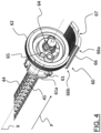
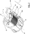
- the last dose setting device 60 comprises a pinion 62 coupled within the outer case 20 at a fixed axial position of the outer case 20 and a rack 66 engaged with the pinion 62 and slidingly coupled with an internal surface of the outer case 20.
- the fixed axial position of the pinion 62 within the outer case 20 is defined by positioning a collar 61a formed at a free end of a mandrel 61 of the pinion 62 in abutment against an abutment surface 21 projecting radially inwardly from the internal surface of the outer case 20 and by positioning a free end portion 61b (or the collar 61a) of the mandrel 61 in abutment against another abutment surface 22 projecting radially inwardly from the internal surface of the outer case 20.
- the pinion 62 is arranged coaxially to the longitudinal axis X and includes a central hole 64 coupled with the piston rod 44.
- the coupling between the pinion 62 and the piston rod 44 is such that during the dose setting operation the piston rod 44 drags in rotation the pinion 62 whereas during the dose delivery operation the piston rod 44 slides axially within the central hole 64.
- the piston rod 44 has a longitudinal planar surface 45 and the central hole 64 has a planar profile portion 65 coupled to the longitudinal planar surface 45.
- two ribs 63 are formed on the internal surface of the outer case 20 on a portion of the latter arranged on the opposite side of the rack 66, so that the pinion 62 is arranged between the ribs 63 and the rack 66.
- the ribs 63 are preferably located on the opposite sides with respect to a radial plane of the pinion 62 coinciding with a longitudinal median plane of the rack 66.
- a clockwise rotation of the pinion 62 causes an axial movement of the rack 66 toward the cartridge housing 16, that is along the distal direction
- a counterclockwise rotation of the pinion 62 causes an axial movement of the rack 66 toward the dose setting sleeve 46, that is along the proximal direction.
- the axial movement of the rack 66 is obtained thanks to the sliding coupling between an axial guide groove 67 formed in the rack 66 and extending along the longitudinal direction X and an axial guide rail 25 provided on an internal surface of the outer case 20 and also extending along the longitudinal direction X.
- the rack 66 is designed such that the axial length travelled by the rack 66 during all the dose setting operations performed in order to delivery the maximum dispensable drug volume initially contained in the cartridge 17 is correlated to such a whole drug volume.
- the rack 66 has a predetermined axial dimension which is equal or proportional to an axial length travelled by the piston rod 44 for delivering the abovementioned whole drug volume.
- the rack 66 is at a new axial position closer to the cartridge 17 than the previously second axial position.
- An example of the new axial position reached by the rack 66 is shown in figure 4 .
Landscapes
- Health & Medical Sciences (AREA)
- Vascular Medicine (AREA)
- Engineering & Computer Science (AREA)
- Anesthesiology (AREA)
- Biomedical Technology (AREA)
- Heart & Thoracic Surgery (AREA)
- Hematology (AREA)
- Life Sciences & Earth Sciences (AREA)
- Animal Behavior & Ethology (AREA)
- General Health & Medical Sciences (AREA)
- Public Health (AREA)
- Veterinary Medicine (AREA)
- Infusion, Injection, And Reservoir Apparatuses (AREA)
- Acyclic And Carbocyclic Compounds In Medicinal Compositions (AREA)
Claims (14)
- Medikamenteninjektionsvorrichtung (10), umfassend:- ein Patronengehäuse (16), das sich entlang einer Längsachse (X) erstreckt und dazu konfiguriert ist, eine Patrone (17) aufzunehmen, die ein vorbestimmtes Medikamentenvolumen enthält;- einen Dosiseinstellmechanismus (30), der dazu konfiguriert ist, eine aus der Patrone (17) abzugebende Medikamentendosis einzustellen;- einen Dosisabgabemechanismus (40), der dazu konfiguriert ist, die durch den Dosiseinstellmechanismus (30) eingestellte Medikamentendosis abzugeben;wobei der Dosiseinstellmechanismus (30) umfasst:- ein Dosiseinstelldienstelement (44), das dazu konfiguriert ist, sich während der Medikamentendosiseinstellung um die Längsachse (X) zu drehen;- eine Einstellvorrichtung (60) der letzten Dosis, die dazu konfiguriert ist, einen Benutzer zu hindern, eine Medikamentendosis einzustellen, die größer als das in der Patrone (17) nach mindestens einer vorherigen Medikamentendosisabgabe verbleibende Medikamentenvolumen ist, wobei die Einstellvorrichtung (60) der letzten Dosis umfasst:- ein Ritzel (62), das koaxial zu der Längsachse (X) in einer axialen Festposition in Bezug auf das Patronengehäuse (16) angeordnet ist;- eine Zahnstange (66), die mit dem Ritzel (62) in Eingriff steht und entlang einer Längsrichtung (P) parallel zur Längsachse (X) beweglich ist, wenn sich das Ritzel (62) dreht;dadurch gekennzeichnet, dass das Ritzel (62) dazu konfiguriert ist, sich zusammen mit dem Dosiseinstelldienstelement (44) während der Medikamentendosiseinstellung um die Längsachse (X) zu drehen, und dass das Ritzel (62) und die Zahnstange (66) gegenseitige Angrenzenelemente (70, 80) aufweisen, die dazu konfiguriert sind, aneinander anzugrenzen und eine weitere Drehung des Ritzels (62) zu verhindern, nachdem die Zahnstange (66) eine axiale Länge zurückgelegt hat, die dem vorbestimmten Medikamentenvolumen zugeordnet ist.
- Medikamenteninjektionsvorrichtung (10) nach Anspruch 1, wobei während der Medikamentendosiseinstellung das Dosiseinstelldienstelement (44) so eingerichtet ist, sich nicht entlang der Längsrichtung (P) zu bewegen.
- Medikamenteninjektionsvorrichtung (10) nach Anspruch 1 oder 2, wobei das Dosiseinstelldienstelement (44) dazu konfiguriert ist, sich während der Medikamentendosisabgabe entlang der Längsrichtung (P) zu dem Patronengehäuse (16) zu bewegen.
- Medikamenteninjektionsvorrichtung (10) nach Anspruch 3, wobei das Dosiseinstelldienstelement (44) während der Medikamentendosisabgabe so eingerichtet ist, sich nicht um die Längsachse (X) zu drehen.
- Medikamenteninjektionsvorrichtung (10) nach Anspruch 3 oder 4, wobei die Zahnstange (66) eine vorbestimmte axiale Abmessung aufweist, die einer axialen Länge zugeordnet ist, die von dem Dosiseinstelldienstelement (44) zur Abgabe des vorbestimmten Medikamentenvolumens zurückgelegt wird.
- Medikamenteninjektionsvorrichtung (10) nach einem der vorhergehenden Ansprüche, wobei das Ritzel (62), bevor eine erste Medikamentendosis eingestellt wird, an einem ersten freien Ende (66a) der Zahnstange (66) näher am Patronengehäuse (16) angeordnet ist und wobei das Ritzel (62), nachdem die letzte Medikamentendosis eingestellt hat, an einem zweiten freien Ende (66b) der Zahnstange (66) gegenüber dem ersten freien Ende (66a) der Zahnstange (66) angeordnet ist.
- Medikamenteninjektionsvorrichtung (10) nach einem der vorhergehenden Ansprüche, wobei die gegenseitigen Angrenzenelemente (70, 80) ein erstes Drehendhalteelement (70) umfassen, das dem Ritzel (62) zugeordnet ist und ein zweites Drehendhalteelement (80) umfassen, das der Zahnstange (66) zugeordnet ist.
- Medikamenteninjektionsvorrichtung (10) nach Anspruch 7 wenn in Abhängigkeit von Anspruch 6, wobei das erste Drehendhalteelement (70) einer Fläche (62a) des Ritzels (62) zugeordnet ist, die auf die gegenüberliegende Seite in Bezug auf das Patronengehäuse (16) positioniert ist und wobei das zweite Drehendhalteelement (80) am zweiten freien Ende (66b) der Zahnstange (66) angeordnet ist.
- Medikamenteninjektionsvorrichtung (10) nach einem der vorhergehenden Ansprüche, wobei die Zahnstange (66) gleitend mit einem Außenkasten (20) der Medikamenteninjektionsvorrichtung (10) gekoppelt ist.
- Medikamenteninjektionsvorrichtung (10) nach Anspruch 9, wobei die Zahnstange (66) eine axiale Führungsnut (67) aufweist, die gleitend mit einer axialen Führungsschiene (25) gekoppelt ist, die an einer Innenfläche des Aussenkastens (20) der Medikamenteninjektionsvorrichtung (10) vorgesehen ist.
- Medikamenteninjektionsvorrichtung (10) nach Anspruch 9 oder 10, wobei das Ritzel (62) zwischen der Zahnstange (66) und mindestens einer Rippe (63) angeordnet ist, die an einer Innenfläche des Außenkastens (20) ausgebildet wird, die sich auf die in Bezug auf die Zahnstange (66) gegenüberliegende Seite befindet.
- Medikamenteninjektionsvorrichtung (10) nach einem der vorhergehenden Ansprüche, wobei das Dosiseinstelldienstelement (44) mindestens eine ebene Fläche (45) aufweist und das Ritzel (62) mindestens einen ebenen Profilabschnitt (65) aufweist, der mit der mindestens einen ebenen Fläche (45) des Dosiseinstelldienstelements (44) gekoppelt ist.
- Medikamenteninjektionsvorrichtung (10) nach einem der vorhergehenden Ansprüche, wobei das Dosiseinstelldienstelement (44) eine Kolbenstange (44) ist, die sich entlang der Längsachse (X) erstreckt.
- Medikamenteninjektionsvorrichtung (10) nach Anspruch 13, wenn in Abhängigkeit von Anspruch 12, wobei das Ritzel (62) eine Zentralbohrung (64) aufweist, die mit der Kolbenstange (44) gekoppelt ist, und wobei der mindestens eine ebene Profilabschnitt (65) durch einen Flächenabschnitt der Zentralbohrung (64) definiert wird.
Applications Claiming Priority (1)
| Application Number | Priority Date | Filing Date | Title |
|---|---|---|---|
| IT102021000012020A IT202100012020A1 (it) | 2021-05-11 | 2021-05-11 | Dispositivo di iniezione di un farmaco |
Publications (3)
| Publication Number | Publication Date |
|---|---|
| EP4088764A1 EP4088764A1 (de) | 2022-11-16 |
| EP4088764B1 true EP4088764B1 (de) | 2025-07-02 |
| EP4088764C0 EP4088764C0 (de) | 2025-07-02 |
Family
ID=77022085
Family Applications (1)
| Application Number | Title | Priority Date | Filing Date |
|---|---|---|---|
| EP22172246.5A Active EP4088764B1 (de) | 2021-05-11 | 2022-05-09 | Medikamenteninjektionsgerät |
Country Status (7)
| Country | Link |
|---|---|
| US (1) | US11696987B2 (de) |
| EP (1) | EP4088764B1 (de) |
| CN (1) | CN115317723B (de) |
| ES (1) | ES3038633T3 (de) |
| HU (1) | HUE072854T2 (de) |
| IT (1) | IT202100012020A1 (de) |
| PL (1) | PL4088764T3 (de) |
Families Citing this family (1)
| Publication number | Priority date | Publication date | Assignee | Title |
|---|---|---|---|---|
| USD1071166S1 (en) * | 2023-10-12 | 2025-04-15 | Stevanato Group S.P.A. | Medical syringe |
Family Cites Families (15)
| Publication number | Priority date | Publication date | Assignee | Title |
|---|---|---|---|---|
| GB9503969D0 (en) * | 1995-02-28 | 1995-04-19 | Sams Bernard | Incrementing mechanism |
| JP4350525B2 (ja) * | 2002-03-18 | 2009-10-21 | イーライ リリー アンド カンパニー | 機械的利点を与えるギヤーセット付き薬剤分与装置 |
| US20090043264A1 (en) * | 2005-04-24 | 2009-02-12 | Novo Nordisk A/S | Injection Device |
| DE102007026083A1 (de) | 2007-05-25 | 2008-11-27 | Haselmeier S.A.R.L. | Injektionsgerät |
| RU2515486C2 (ru) * | 2008-12-12 | 2014-05-10 | Санофи-Авентис Дойчланд Гмбх | Механизм привода с установкой в исходное состояние для устройства подачи лекарственного средства и устройство подачи лекарственного средства |
| CA2774563A1 (en) * | 2009-09-30 | 2011-04-07 | Sanofi-Aventis Deutschland Gmbh | Drive mechanism for a drug delivery device |
| DE202012001411U1 (de) | 2012-02-10 | 2013-05-13 | Haselmeier Gmbh | Injektionsgerät |
| WO2014166904A1 (en) * | 2013-04-10 | 2014-10-16 | Sanofi | Hand-held drug injection device and dose setting limiter mechanism therefor |
| EP3046606A1 (de) * | 2013-09-16 | 2016-07-27 | Novo Nordisk A/S | Injektionsvorrichtung zur selektiven fixen oder variablen dosierung |
| CN105579085B (zh) * | 2013-09-23 | 2019-09-27 | 赛诺菲-安万特德国有限公司 | 用于药物输送装置的组件和药物输送装置 |
| EP3057629B1 (de) * | 2013-10-16 | 2021-12-08 | Novo Nordisk A/S | Medikamentenabgabevorrichtung mit bremsvorrichtung |
| WO2016016184A1 (en) * | 2014-07-28 | 2016-02-04 | Novo Nordisk A/S | A stop mechanism for a hypocycloid end-of-content mechanism in an injection device |
| EP3162397B1 (de) * | 2015-10-29 | 2019-07-31 | TecPharma Licensing AG | Dosiseinstellmechanismus für eine spritzgiessmaschine mit einem dosisbegrenzer |
| GB201615455D0 (en) | 2016-09-12 | 2016-10-26 | Norton Healthcare Ltd | Last dose protection |
| WO2020205255A1 (en) * | 2019-03-29 | 2020-10-08 | Eli Lilly And Company | Medication delivery device with gear set dosage system |
-
2021
- 2021-05-11 IT IT102021000012020A patent/IT202100012020A1/it unknown
-
2022
- 2022-05-09 PL PL22172246.5T patent/PL4088764T3/pl unknown
- 2022-05-09 EP EP22172246.5A patent/EP4088764B1/de active Active
- 2022-05-09 HU HUE22172246A patent/HUE072854T2/hu unknown
- 2022-05-09 ES ES22172246T patent/ES3038633T3/es active Active
- 2022-05-11 US US17/662,854 patent/US11696987B2/en active Active
- 2022-05-11 CN CN202210511448.4A patent/CN115317723B/zh active Active
Also Published As
| Publication number | Publication date |
|---|---|
| US20220362477A1 (en) | 2022-11-17 |
| CN115317723B (zh) | 2026-02-24 |
| ES3038633T3 (en) | 2025-10-14 |
| PL4088764T3 (pl) | 2025-10-06 |
| HUE072854T2 (hu) | 2025-12-28 |
| EP4088764C0 (de) | 2025-07-02 |
| CN115317723A (zh) | 2022-11-11 |
| US11696987B2 (en) | 2023-07-11 |
| IT202100012020A1 (it) | 2022-11-11 |
| EP4088764A1 (de) | 2022-11-16 |
Similar Documents
| Publication | Publication Date | Title |
|---|---|---|
| KR101566132B1 (ko) | 주입 장치 | |
| JP5001001B2 (ja) | 医薬品送達装置において使用されるのに適した投与量ダイヤルおよび駆動機構 | |
| KR101544682B1 (ko) | 주입 장치 | |
| EP2493533B1 (de) | Automatischer applikator für flüssige pharmazeutische zubereitungen, im besonderen für insulin | |
| EP2586478B1 (de) | Injektor mit einem reaktivierbaren element | |
| EP3164172B1 (de) | Federanordnung und arzneimittelabgabevorrichtung hiermit | |
| EP2351591A1 (de) | Anordnung für eine Arzneimittelabgabevorrichtung und Arzneimittelabgabevorrichtung | |
| EP2452711A1 (de) | Antriebsmechanismus für eine Arzneimittelabgabevorrichtung und Arzneimittelabgabevorrichtung | |
| EP0918555A2 (de) | Inkrementierungsmechanismus, insbesondere zum gebrauch mit einer medizinischen spritze | |
| US20250073395A1 (en) | Drive mechanism for an injection device | |
| EP4088764B1 (de) | Medikamenteninjektionsgerät | |
| US11918790B2 (en) | Drug injection device | |
| EP3337540B1 (de) | Medikamentenverabreichungsvorrichtung | |
| EP3397323B1 (de) | Medikamentenverabreichungsvorrichtung |
Legal Events
| Date | Code | Title | Description |
|---|---|---|---|
| PUAI | Public reference made under article 153(3) epc to a published international application that has entered the european phase |
Free format text: ORIGINAL CODE: 0009012 |
|
| STAA | Information on the status of an ep patent application or granted ep patent |
Free format text: STATUS: THE APPLICATION HAS BEEN PUBLISHED |
|
| AK | Designated contracting states |
Kind code of ref document: A1 Designated state(s): AL AT BE BG CH CY CZ DE DK EE ES FI FR GB GR HR HU IE IS IT LI LT LU LV MC MK MT NL NO PL PT RO RS SE SI SK SM TR |
|
| STAA | Information on the status of an ep patent application or granted ep patent |
Free format text: STATUS: REQUEST FOR EXAMINATION WAS MADE |
|
| 17P | Request for examination filed |
Effective date: 20230509 |
|
| P01 | Opt-out of the competence of the unified patent court (upc) registered |
Effective date: 20230508 |
|
| RBV | Designated contracting states (corrected) |
Designated state(s): AL AT BE BG CH CY CZ DE DK EE ES FI FR GB GR HR HU IE IS IT LI LT LU LV MC MK MT NL NO PL PT RO RS SE SI SK SM TR |
|
| GRAP | Despatch of communication of intention to grant a patent |
Free format text: ORIGINAL CODE: EPIDOSNIGR1 |
|
| STAA | Information on the status of an ep patent application or granted ep patent |
Free format text: STATUS: GRANT OF PATENT IS INTENDED |
|
| INTG | Intention to grant announced |
Effective date: 20250212 |
|
| GRAS | Grant fee paid |
Free format text: ORIGINAL CODE: EPIDOSNIGR3 |
|
| GRAA | (expected) grant |
Free format text: ORIGINAL CODE: 0009210 |
|
| STAA | Information on the status of an ep patent application or granted ep patent |
Free format text: STATUS: THE PATENT HAS BEEN GRANTED |
|
| AK | Designated contracting states |
Kind code of ref document: B1 Designated state(s): AL AT BE BG CH CY CZ DE DK EE ES FI FR GB GR HR HU IE IS IT LI LT LU LV MC MK MT NL NO PL PT RO RS SE SI SK SM TR |
|
| REG | Reference to a national code |
Ref country code: GB Ref legal event code: FG4D |
|
| REG | Reference to a national code |
Ref country code: CH Ref legal event code: EP |
|
| REG | Reference to a national code |
Ref country code: DE Ref legal event code: R096 Ref document number: 602022016704 Country of ref document: DE |
|
| REG | Reference to a national code |
Ref country code: IE Ref legal event code: FG4D |
|
| U01 | Request for unitary effect filed |
Effective date: 20250715 |
|
| U07 | Unitary effect registered |
Designated state(s): AT BE BG DE DK EE FI FR IT LT LU LV MT NL PT RO SE SI Effective date: 20250721 |
|
| REG | Reference to a national code |
Ref country code: ES Ref legal event code: FG2A Ref document number: 3038633 Country of ref document: ES Kind code of ref document: T3 Effective date: 20251014 |
|
| REG | Reference to a national code |
Ref country code: GR Ref legal event code: EP Ref document number: 20250401965 Country of ref document: GR Effective date: 20251112 |
|
| REG | Reference to a national code |
Ref country code: HU Ref legal event code: AG4A Ref document number: E072854 Country of ref document: HU |
|
| PG25 | Lapsed in a contracting state [announced via postgrant information from national office to epo] |
Ref country code: IS Free format text: LAPSE BECAUSE OF FAILURE TO SUBMIT A TRANSLATION OF THE DESCRIPTION OR TO PAY THE FEE WITHIN THE PRESCRIBED TIME-LIMIT Effective date: 20251102 |
|
| PG25 | Lapsed in a contracting state [announced via postgrant information from national office to epo] |
Ref country code: NO Free format text: LAPSE BECAUSE OF FAILURE TO SUBMIT A TRANSLATION OF THE DESCRIPTION OR TO PAY THE FEE WITHIN THE PRESCRIBED TIME-LIMIT Effective date: 20251002 |
|
| PG25 | Lapsed in a contracting state [announced via postgrant information from national office to epo] |
Ref country code: HR Free format text: LAPSE BECAUSE OF FAILURE TO SUBMIT A TRANSLATION OF THE DESCRIPTION OR TO PAY THE FEE WITHIN THE PRESCRIBED TIME-LIMIT Effective date: 20250702 |
|
| PG25 | Lapsed in a contracting state [announced via postgrant information from national office to epo] |
Ref country code: RS Free format text: LAPSE BECAUSE OF FAILURE TO SUBMIT A TRANSLATION OF THE DESCRIPTION OR TO PAY THE FEE WITHIN THE PRESCRIBED TIME-LIMIT Effective date: 20251002 |
|
| PG25 | Lapsed in a contracting state [announced via postgrant information from national office to epo] |
Ref country code: SM Free format text: LAPSE BECAUSE OF FAILURE TO SUBMIT A TRANSLATION OF THE DESCRIPTION OR TO PAY THE FEE WITHIN THE PRESCRIBED TIME-LIMIT Effective date: 20250702 |
|
| PG25 | Lapsed in a contracting state [announced via postgrant information from national office to epo] |
Ref country code: SK Free format text: LAPSE BECAUSE OF FAILURE TO SUBMIT A TRANSLATION OF THE DESCRIPTION OR TO PAY THE FEE WITHIN THE PRESCRIBED TIME-LIMIT Effective date: 20250702 |