EP4088694A2 - Dispositif médical - Google Patents
Dispositif médical Download PDFInfo
- Publication number
- EP4088694A2 EP4088694A2 EP22171687.1A EP22171687A EP4088694A2 EP 4088694 A2 EP4088694 A2 EP 4088694A2 EP 22171687 A EP22171687 A EP 22171687A EP 4088694 A2 EP4088694 A2 EP 4088694A2
- Authority
- EP
- European Patent Office
- Prior art keywords
- plastic film
- medical device
- support structure
- resilient member
- nasal dilator
- Prior art date
- Legal status (The legal status is an assumption and is not a legal conclusion. Google has not performed a legal analysis and makes no representation as to the accuracy of the status listed.)
- Granted
Links
Images


Classifications
-
- A—HUMAN NECESSITIES
- A61—MEDICAL OR VETERINARY SCIENCE; HYGIENE
- A61F—FILTERS IMPLANTABLE INTO BLOOD VESSELS; PROSTHESES; DEVICES PROVIDING PATENCY TO, OR PREVENTING COLLAPSING OF, TUBULAR STRUCTURES OF THE BODY, e.g. STENTS; ORTHOPAEDIC, NURSING OR CONTRACEPTIVE DEVICES; FOMENTATION; TREATMENT OR PROTECTION OF EYES OR EARS; BANDAGES, DRESSINGS OR ABSORBENT PADS; FIRST-AID KITS
- A61F5/00—Orthopaedic methods or devices for non-surgical treatment of bones or joints; Nursing devices ; Anti-rape devices
- A61F5/01—Orthopaedic devices, e.g. long-term immobilising or pressure directing devices for treating broken or deformed bones such as splints, casts or braces
- A61F5/08—Devices for correcting deformities of the nose ; Devices for enlarging the nostril, e.g. for breathing improvement
-
- A—HUMAN NECESSITIES
- A61—MEDICAL OR VETERINARY SCIENCE; HYGIENE
- A61F—FILTERS IMPLANTABLE INTO BLOOD VESSELS; PROSTHESES; DEVICES PROVIDING PATENCY TO, OR PREVENTING COLLAPSING OF, TUBULAR STRUCTURES OF THE BODY, e.g. STENTS; ORTHOPAEDIC, NURSING OR CONTRACEPTIVE DEVICES; FOMENTATION; TREATMENT OR PROTECTION OF EYES OR EARS; BANDAGES, DRESSINGS OR ABSORBENT PADS; FIRST-AID KITS
- A61F13/00—Bandages or dressings; Absorbent pads
- A61F13/02—Adhesive bandages or dressings
- A61F13/023—Adhesive bandages or dressings wound covering film layers without a fluid retention layer
-
- A—HUMAN NECESSITIES
- A61—MEDICAL OR VETERINARY SCIENCE; HYGIENE
- A61F—FILTERS IMPLANTABLE INTO BLOOD VESSELS; PROSTHESES; DEVICES PROVIDING PATENCY TO, OR PREVENTING COLLAPSING OF, TUBULAR STRUCTURES OF THE BODY, e.g. STENTS; ORTHOPAEDIC, NURSING OR CONTRACEPTIVE DEVICES; FOMENTATION; TREATMENT OR PROTECTION OF EYES OR EARS; BANDAGES, DRESSINGS OR ABSORBENT PADS; FIRST-AID KITS
- A61F13/00—Bandages or dressings; Absorbent pads
- A61F13/12—Bandages or dressings; Absorbent pads specially adapted for the head or neck
- A61F13/122—Bandages or dressings; Absorbent pads specially adapted for the head or neck specially adapted for the face
- A61F13/126—Bandages or dressings; Absorbent pads specially adapted for the head or neck specially adapted for the face specially adapted for the nose
Definitions
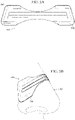
- the present disclosure relates to a medical device as well as to a nasal dilator as well as to a method using a nasal dilator.
- a medical device comprising a plastic film and a support structure.
- the plastic film may be a flimsy plastic film that, for lack of intrinsic stability, droops during handling by a user, e.g. when the user is attempting to adhere the medical device to a person's skin.
- the support structure can inhibit such drooping by supporting at least a portion of the plastic film, thus making it easier for the user to accurately apply the medical device to a person's skin and/or preventing sections of the medical device from contacting other sections of the medical device, in particular adhesive sections, in a manner that could degrade the utility of the medical device.
- the support structure may be manually inseparable from the plastic film, which can ease overall handling of the medical device and prevent misuse that could degrade the utility of the medical device.
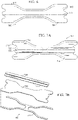
- a nasal dilator comprising a plastic film, at least one resilient member and tripartite release liner.
- the plastic film may be a flimsy plastic film that, for lack of intrinsic stability, droops during handling by a user, e.g. when the user is attempting to adhere the nasal dilator to their nose.
- the tripartite release liner can inhibit such drooping by retaining support for at least a portion of the plastic film during application to a user's nose, thus making it easier for the user to accurately apply the nasal dilator and/or preventing sections of the nasal dilator from contacting other sections of the nasal dilator, in particular adhesive sections, in a manner that could degrade the utility of the nasal dilator.
- the present disclosure discloses a medical device.
- the medical device may be a bandage, a wound care article, or a nasal dilator, in particular an external nasal dilator.
- the medical device may be a (thin, supple, or flexible) medical device, e.g. a medical device adhesively securable to human skin.
- the medical device may comprise a plastic film.
- the plastic film may have a thickness of less than 0.1 mm, less than 0.05 mm, or less than 0.025 mm.
- the plastic film may be a medical grade and/or a biocompatible film.
- the plastic film may be a thermoplastic and/or polyurethane film.
- the plastic film may be a microporous film.
- the plastic film may comprise at least 20 pores, at least 50 pores or at least 100 pores per square centimeter. Each of the pores may have a respective maximum diameter of less than 2 ⁇ m, less than 5 ⁇ m, or less than 10 ⁇ m.
- the plastic film may be devoid of pores or openings having a diameter larger than 2 ⁇ m, 5 ⁇ m, or 10 ⁇ m.
- the plastic film may have a moisture vapor transmission rate of at least 200 grams, at least 400 grams, or at least 800 grams per square meter per 24 hours.
- the moisture vapor transmission rate may be determined by a standard test such as, for example, ASTM F1249, ASTM E96, or ASTM2622.
- the medical device and/or plastic film may be dimensioned such that a maximum length along a longitudinal axis of the medical device / plastic film is not more than 10 times, not more than 5 times, or not more than 2 times a maximum width of the medical device / plastic film along a transverse axis perpendicular to the longitudinal axis.
- the medical device and/or plastic film may have a(n overall and/or general) shape of a quadrilateral, e.g. the shape of a rectangle, square, kite, parallelogram, trapezoid or rhombus.
- the medical device and/or plastic film may have a(n overall and/or general) shape of an oval, circle, polygon, or star.
- the medical device and/or plastic film may have a(n overall and/or general) shape of a dog-bone or barbell.
- a dog-bone or barbell shape may be understood as a shape consisting of two identical rectangles joined by a third rectangle, the three rectangles sharing a common axis of symmetry that constitutes a longitudinal axis of the dog-bone or barbell shape, the third rectangle having a width perpendicular to the longitudinal axis that is at least 10% or at least 20% less than a respective, individual width of the two identical rectangles perpendicular to the longitudinal axis.
- the medical device and/or plastic film may have a(n overall and/or general) butterfly shape.
- a dog-butterfly shape may be understood as a shape consisting of two identical (isosceles) triangles joined by a rectangle, the rectangle having a width perpendicular to an axis of symmetry of the rectangle that extends from the one triangle to the other that is at least 10% or at least 20% less than a respective, individual width of the two triangles perpendicular to said axis of symmetry of the rectangle.
- the two triangles may share a common axis of symmetry with the rectangle.f
- the shape need not be geometrically perfect, i.e. need not be a geometrically perfect rectangular, square, kite, circular, polygon, star, dog-bone, etc.
- the medical device and/or plastic film may be shaped such that an imaginary area of any one of the aforementioned shapes (rectangular, square, kite, circular, polygon, star, dog-bone, etc.) may be found such that not more than 15%, not more than 10% or not more than 5% of a total area of the medical device / plastic film does not overlap / coincide with the imaginary area, i.e. falls outside the imaginary area and/or is void, i.e. not present, within the bounds of the imaginary area.
- an imaginary area of any one of the aforementioned shapes rectangular, square, kite, circular, polygon, star, dog-bone, etc.
- the outermost peripheral edge of the plastic film may define an entire outermost peripheral edge of the medical device or at least 60%, at least 80%, or at least 90% of an entire outermost peripheral edge of the medical device.
- the plastic film may be an elastic film.
- the plastic film may be capable of stretching elastically in response to a (dilating / stretching) force in the plane of the plastic film.
- the plastic film may inherently return to an initial, unbiased state in response to cessation of such a (dilating / stretching) force.
- the plastic film, per se may have insufficient intrinsic stability to retain a(n overall) shape, e.g. at a macroscopic level (of observation) and/or in response to forces perpendicular to the plane of the plastic film. More specifically, the plastic film, per se, may have insufficient intrinsic stability to retain a(n overall) planar shape against (forces perpendicular to the plane of the plastic film arising from) standard gravity, e.g.
- the plastic film ( per se) may be incapable of retaining a (macroscopically) planar shape in a cantilever arrangement in which the plastic film extends horizontally from a support by more than 4 mm or more than 8 mm.
- the plastic film ( per se) may bend (as a result of its own mass) with a radius of curvature less than 2 mm, less than 1 mm or less than 0.5 mm when subjected to standard gravity, e.g. when the plastic film is in a cantilever arrangement (where a portion of the plastic film is supported and a remaining, extending portion is permitted to (freely) droop in response to gravity).
- the expression “ per se” may be understood as meaning “in and of itself” or “on its own” or “by itself”.
- an "intrinsic stability of the plastic film, per se” may be understood as meaning an intrinsic stability (purely) of the plastic film itself, i.e. as if the plastic film were a homogeneous plastic film (devoid of any support structure).
- the plastic film may comprise a first major surface and a second major surface.
- the first major surface of the plastic film may (be a surface configured to) face a user's skin during use.
- At least 10%, at least 20%, at least 50%, at least 80%, or at least 90% of the first major surface of the plastic film may be coated with a (biocompatible) adhesive, e.g. for (releasably) affixing the medical device to a user's skin.
- the adhesive may be a pressure-sensitive adhesive.
- the medical device may comprise a support structure, e.g. a support structure that supports (an area of) the plastic film.
- the support structure may (visually and/or materially) distinct from the plastic film. Regardless of whether the support structure is (visually and/or materially) distinct from the plastic film, the support structure may be integrally formed with the plastic film and/or may be an integral component of the plastic film.
- the support structure may support (an area of) the plastic film such that the plastic film is inhibited from curling and/or folding against itself / against other portions of the medical device.
- the support structure may support (an area of) the plastic film such that an entire area of the plastic film or such that at least 60%, at least 80%, at least 90%, or at least 95% of an entire area of the plastic film is inhibited from (macroscopically) deforming.
- the area inhibited from deforming may be inhibited from deforming, e.g. bending (as a result of the mass of the plastic film) to a radius of curvature less than 5 mm, less than 10 mm or less than 20 mm when subjected to standard gravity.
- the ability of the support structure to inhibit such deforming of an entire area / a percentage of an entire area of the plastic film may be independent of an orientation (of the medical device).
- the support structure may inhibit such deforming regardless of an orientation (of the medical device).
- the support structure may comprise / consist of a plurality of components, e.g. a plurality of discrete components, a plurality of permanently joined components, a plurality of integrally-formed components, or a combination of discrete and/or permanently joined and/or integrally-formed components.
- the plurality of components may comprise, e.g. as described in further detail infra, any combination of components individually selected from the group consisting of a resilient member, a strut, a strip of (sheet-shaped) material, a support member and a fiber.
- the support structure may be affixed to the first major surface of the plastic film.
- the support structure may be affixed to the second major surface of the plastic film.
- a first set of (components belonging to) the plurality of components (belonging to the support structure) may be affixed to the first major surface of the plastic film, and a second set of (components belonging to) the plurality of components (belonging to the support structure) may be affixed to the second major surface of the plastic film.
- the first and second sets may collectively constitute the plurality of components.
- the support structure may be (manually) inseparable from the plastic film, e.g. in the sense that the support structure may be affixed to and/or integrated into the plastic film in a manner that inhibits and/or prevents the support structure from being (manually) separated from the plastic film (without incurring damage to the support structure and/or the plastic film, e.g. damage that would impair the function of the support structure and/or the plastic film).
- the term "manually” may be understood as meaning using (no other tool than) human hands.
- the medical device may comprise a (sheet-like) release liner that covers the adhesive on the first major surface of the plastic film (prior to use).
- the release liner may be releasably adhered to the plastic film (via the adhesive).
- the release liner may be manually removable from the medical device, e.g. to expose the adhesive (immediately prior to affixing the medical device to a user's skin).
- the release liner may support (an area of) the plastic film such that the plastic film is inhibited from curling and/or folding against itself / against other portions of the medical device.
- the release liner may support (an area of) the plastic film such that an entire area of the plastic film or such that at least 60%, at least 80%, at least 90%, or at least 95% of an entire area of the plastic film is inhibited from (macroscopically) deforming.
- the area inhibited from deforming may be inhibited from deforming, e.g. bending (as a result of the mass of the plastic film) to a radius of curvature less than 5 mm, less than 10 mm or less than 20 mm when subjected to standard gravity.
- the ability of the release liner to inhibit such deforming of an entire area / a percentage of an entire area of the plastic film may be independent of an orientation (of the medical device).
- the release liner may inhibit such deforming regardless of an orientation (of the medical device).
- the release liner may comprise a substrate of a (Kraft) paper and/or a synthetic material, e.g. a plastic film.
- the substrate may be coated with a release agent, e.g. silicone, or other coating.
- the release liner may constitute an outermost component of the medical device.
- the release liner may be a tripartite release liner.
- the tripartite release liner may consist of a first (liner) portion, a second (liner) portion, and an intermediate (liner) portion.
- the intermediate (liner) portion may be situated intermediate the first (liner) portion and the second (liner) portion.
- Each of the first (liner) portion, the second (liner) portion, and the intermediate (liner) portion may (respectively / individually) constitute not more than 40%, not more than 50%, or not more than 60% of a total (contact) area of the tripartite release liner.
- Each of the first (liner) portion, the second (liner) portion, and the intermediate (liner) portion may (respectively / individually) constitute not less than 20%, or not less than 30% of a total (contact) area of the tripartite release liner.
- the term "contact area” may be understood as the (overall) area of the regions in which the (tripartite) release liner contacts other elements of the medical device.
- the "contact area” may be the total area the plastic film.
- the "contact area" may likewise be the total area the plastic film.
- the intermediate (liner) portion may comprise a first tab and/or a second tab.
- the first tab may overlap the first (liner) portion, e.g. on a side of the first (liner) portion opposite the adhesive.
- the second tab may overlap the second (liner) portion, e.g. on a side of the first (liner) portion opposite the adhesive.
- the first (liner) portion may comprise a third tab.
- the third tab may overlap the intermediate (liner) portion, e.g. on a side of the intermediate (liner) portion opposite the adhesive.
- the second (liner) portion may comprise a fourth tab.
- the fourth tab may overlap the intermediate (liner) portion, e.g. on a side of the intermediate (liner) portion opposite the adhesive.
- the medical device may comprise a (manually removable) cover liner.
- the cover liner may be (manually removably) affixed, e.g. via an adhesive, to an outermost (excepting the cover liner) surface of the medical device, e.g. to the second major surface of the plastic film.
- the cover liner may cover an entire area of the medical device / the plastic film or at least 60%, at least 80%, at least 90%, or at least 95% of an entire area of the medical device / the plastic film.
- the cover liner may comprise a sheet-like material such as (Kraft) paper and/or plastic film.
- the medical device may be devoid of (such) a cover liner.
- the cover liner may constitute an outermost component of the medical device, e.g. on a side of the medical device opposite the release liner.
- the second major surface of the plastic film may face the cover liner.
- the cover liner may be a carrier liner, e.g. a (so-called) carrier liner that provides support to the plastic film during (initial) manufacture and/or (subsequent) transport of the plastic film.
- the medical device may be (manually) deformable, e.g. for the sake of affixing the medical device to an area of human skin (via the adhesive (on the first major surface of the plastic film)).
- Such deformation of the medical device may be a plastic deformation or an elastic deformation.
- the deformation may comprise a bending ( i.e. a plastic or elastic deformation) of the medical device or a (resilient) flexing (i.e. an elastic deformation) of the medical device.
- Deformation of the medical device to affix the medical device to an area of human skin may comprise bending an entirety of the medical device, e.g. such that an entire longitudinal axis of the medical device is bent, e.g.
- the medical device may ( e.g. on account of an optional resiliency of the support structure, which support structure need not comprise a "resilient member" as described below to exhibit resilience) exert return forces in response to the deformation, e.g. return forces that, in the absence of other forces, would return the medical device to an undeformed / unbiased state.
- return forces e.g. return forces that, in the absence of other forces, would return the medical device to an undeformed / unbiased state.
- a medical device devoid of a resilient member e.g. in a bandage and wound care article, at least 60%, at least 80%, or at least 90% of the return forces may emanate from the support structure.
- a medical device comprising a resilient member e.g.
- the return forces emanating from the resilient member(s) may constitute at least 80%, at least 90%, or at least 95% of the (overall) return forces emanating from the medical device.
- the adhesive (on the first major surface of the plastic film) may counteract the (overall) return forces (emanating from the medical device (as a whole)).
- the (overall) return forces (emanating from the medical device (as a whole)) may be of insufficient magnitude to overcome adhesive forces of the adhesive affixing the medical device to the area of human skin.
- the adhesive may retain the medical device on a user's skin despite deformation of the medical device (to conform to a shape of the user's skin (at a location where the medical device is affixed)).
- the support structure may be (manually) deformable, e.g. in response to (manual) forces perpendicular to a (major) planar surface (e.g. as described below) defined by the support structure.
- Such deformation of the support structure may be a plastic deformation or an elastic deformation.
- the deformation may comprise a bending ( i.e. a plastic or elastic deformation) of the support structure or a (resilient) flexing (i.e. an elastic deformation) of the support structure.
- such deformation of the support structure may comprise bending the support structure such that a longitudinal axis of the support structure is bent.
- Deformation of the support structure to affix the medical device to an area of human skin may comprise bending (an entirety of) the support structure, e.g. such that a(n entire) longitudinal axis of the support structure is bent, e.g. at a radius of curvature of at least 60 mm, at least 40 mm, or at least 20 mm.
- the support structure may ( e.g. on account of an optional resiliency of the support structure, which support structure need not comprise a "resilient member" as described below to exhibit resilience) exert return forces in response to the deformation, e.g. return forces that, in the absence of other forces, would return the support structure to an undeformed / unbiased state.
- the adhesive may counteract the return forces (emanating from the support structure).
- the return forces (emanating from the support structure) may be of insufficient magnitude to overcome adhesive forces of the adhesive affixing the medical device to the area of human skin.
- the adhesive may retain the medical device on a user's skin despite deformation of the medical device / the support structure (to conform to a shape of the user's skin (at a location where the medical device is affixed)).
- the support structure may exhibit rigidity and/or no (macroscopic) elasticity in response to (manual) forces parallel to a (major) planar surface (e.g. as described below) defined by the support structure.
- the support structure (e.g. in an unbiased state) may define a (major) planar surface. More specifically, the support structure (e.g. in an unbiased state) may define a plurality of support regions (in planar arrangement) that define a (major) planar surface and/or correspond to regions of a (major) planar surface.
- the support regions may be regions (of the support structure) that contact and/or support the plastic film.
- the support regions may be distributed such that any contiguous region - defined by the intersection of a rectangular bounding box and an area bounded by an outermost perimeter of the plastic film and constituting 20% of the total area of the plastic film - is supported by / contacts not less than 10% or not less than 5% of a total area of the support regions.
- the support regions may be distributed such that any contiguous region - defined by the intersection of a rectangular bounding box and an area bounded by an outermost perimeter of the plastic film and constituting 10% of the total area of the plastic film - is supported by / contacts not less than 5% or not less than 2% of a total area of the support regions.
- the support structure may be a sheet-like structure.
- the support structure may have a(n overall) planar / sheet-like shape.
- the support structure may have a (maximum) thickness of less than 2 mm, less than 1 mm, or less than 0.5 mm (in a direction perpendicular to the defined (major) planar surface.
- the support structure may fit between two imaginary parallel planes separated by 2 mm, 1 mm, or 0.5 mm.
- the support structure may occupy less than 40%, less than 20%, less than 20%, less than 5%, or less than 2% of the entire area of the plastic film. More specifically, a total area occupied by the support structure, e.g. as viewed in a direction perpendicular to a major surface of the support structure and/or the plastic film, may be less than 40%, less than 20%, less than 20%, less than 5%, or less than 2% of the total area of the plastic film. Similarly, a total area occupied by the support regions of the support structure, e.g. as viewed in a direction perpendicular to a major surface of the support structure and/or the plastic film, may be less than 40%, less than 20%, less than 20%, less than 5%, or less than 2% of the total area of the plastic film.
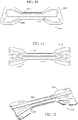
- the medical device may comprise at least one resilient member.
- the term "resilient member” may be understood as a component of the medical device configured to provide therapeutic function by stretching and/or dilating an anatomical structure of a user, e.g. a nasal passage. Additionally or alternatively, the term “resilient member” may be understood as a component of the medical device configured to be flexed over the bridge of a user's nose to dilate a nasal passage.
- the at least one resilient member may constitute a (direct) sub-component of the medical device, per se, or may constitute a sub-sub-component of the medical device, namely a sub-component of the "support structure" sub-component of the medical device.
- the at least one resilient member may constitute a sub-component of the support structure, i.e. may constitute a tertiary (sub-sub-) level component of the medical device.
- the at least one resilient member may constitute a sub-component of the medical device, per se , i.e. may constitute a secondary (sub-) level component of the medical device.
- descriptions of embodiments comprising a tripartite release liner need not employ the "support structure" nomenclature in references to the at least one resilient member, i.e. may forsake the intermediate concept of a "support structure”.
- the support structure may comprise the at least one resilient member.
- each of the at least one resilient member may constitute a corresponding component of the support structure.
- the support structure may comprise at least one support element, e.g. for supporting the plastic film in regions not sufficiently supported by the at least one resilient member.
- the support structure may consist of the at least one resilient member and the at least one support element.
- the term "resilient member" may be understood, additionally or alternatively to the previous descriptions, as a component of the support structure that (even in weakest arrangement) provides a supporting force several orders of magnitude larger, e.g.
- the term "resilient member” may be understood as encompassing, exclusively or non-exclusively, a component of the support structure that (in weakest arrangement) exhibits that maximum stiffness of any component of the support structure. Additionally or alternatively, the term “resilient member” may be understood as a component of the support structure that (in weakest arrangement) exhibits a stiffness of at least 20%, at least 40%, at least 60% or at least 80% of a stiffness (in weakest arrangement) of a stiffest (in weakest arrangement) component of the support structure.
- the term "support element” may be understood as a component of the support structure that (in weakest arrangement) has a stiffness less than 1%, less than 5%, less than 10%, or less than 20% of a stiffness (in weakest arrangement) of a stiffest (in weakest arrangement) of the at least one resilient member.
- stiffness may be understood as a stiffness in response to a non-torsional force and/or in response to a force perpendicular to a major surface of the respective component of the support structure.
- the certain component may be understood as constituting a support element if the minimum stiffness A is less than 1%, less than 5%, less than 10%, or less than 20% of the largest minimum stiffness B n respectively, individually exhibited by any one of the at least one resilient member.
- the support structure may comprise / consist of a plurality of fibers.
- Each fiber of the plurality of fibers may constitute a support element of the support structure.
- the plurality of fibers may comprise / consist of multi-strand fibers, single-strand fibers, or a combination of multi-strand and single-strand fibers.
- the plurality of fibers may comprise / consist of natural fibers, synthetic fibers, or a combination of natural and synthetic fibers.
- the plurality of fibers may comprise / consist of plastically deformable fibers, elastically deformable fibers, or a combination of plastically and elastically deformable fibers.
- the elastically deformable fibers may be (straight) fibers that strive to return to an initial / unbiased state in response to a deformation that bends a longitudinal axis of the respective fiber.
- an entire length of the respective fiber or at least 50% of an entire length of the respective fiber may constitute a support region of the support structure.
- the fibers may be arranged in crisscrossing arrangement.
- the fibers may be arranged in perpendicular arrangement.
- a first set of fibers belonging to the plurality of fibers may be arranged in (straight or zigzag) parallel arrangement, i.e.
- each individual fiber belonging to the first set being (straight / zigzag,) offset and parallel to each other fiber belonging to the first set
- a second set of fibers belonging to the plurality of fibers may be arranged in (straight or zigzag) parallel arrangement, i.e. with each individual fiber belonging to the second set being (straight / zigzag,) offset and parallel to each other fiber belonging to the second set, where (a respective overall longitudinal axis of) each individual fiber of the first set is perpendicular to (a respective overall longitudinal axis of) each individual fiber of the second set.
- the fibers may be arranged in skewed arrangement, e.g.
- a first set of fibers belonging to the plurality of fibers may be arranged in (straight or zigzag) parallel arrangement, i.e. with each individual fiber belonging to the first set being (straight / zigzag,) offset and parallel to each other fiber belonging to the first set, and a second set of fibers belonging to the plurality of fibers may be arranged in (straight or zigzag) parallel arrangement, i.e.
- each individual fiber belonging to the second set being (straight / zigzag,) offset and parallel to each other fiber belonging to the second set, where (a respective overall longitudinal axis of) each individual fiber of the first set is skewed relative to (a respective overall longitudinal axis of) each individual fiber of the second set, e.g. at an angle of not less than 45°, not less than 30° or not less than 20°.
- the support structure may comprise at least one strut, e.g. a strut having an overall longitudinal axis perpendicular or oblique (by at least 45° or by at least 60°) to a longitudinal axis of any one of the at least one resilient member.
- the support structure may comprise at least one strut having an overall longitudinal axis parallel or oblique (by no more than 5° or by no more than 10°) to a longitudinal axis of any one of the at least one resilient member.
- the strut may have a length of less than 90%, or less than 95% of an edge-to-edge dimension of the medical device (as measured along an imaginary line coaxial to a longitudinal axis of the (respective) strut).
- Each longitudinal end of the strut may be distanced from an outermost peripheral edge of the medical device, e.g. by at least 5% or at least 10% of a length of the medical device (along a longitudinal axis of the medical device coaxial to a longitudinal axis of the (respective) strut).
- the strut may have a length of not less than 80%, not less than 90%, or not less than 95% of an edge-to-edge dimension of the medical device (as measured along an imaginary line coaxial to a longitudinal axis of the (respective) strut).
- the ends of the strut may coincide with respective edges of the medical device.
- the strut may be of a natural material, a synthetic material, or a combination of natural and synthetic materials.
- the strut may comprise a thermoplastic resin, e.g. a (biaxially oriented) polyester resin such as (biaxially oriented) poly(ethylene terephthalate), often referred to by the abbreviation boPET / PET.
- the strut may be of the same material as the at least one resilient member.
- the strut may have a maximum thickness that is less than 20%, less than 10%, or less than 5% of a minimum thickness of the at least one resilient member.
- the strut may have a maximum width that is less than a minimum width of the at least one resilient member or less than 50% of the minimum width of the at least one resilient member.
- At least 40%, at least 60%, or at least 80% of a major surface of the strut may be fastened, e.g. glued, to the plastic film.
- the strut may constitute a support element or a resilient element of the support structure.
- the support structure may comprise at least one strip of (sheet-shaped) material.
- the strip of material may be draped across (any of) the at least one resilient member, e.g. on a side of (any of) the at least one resilient member opposite the plastic film.
- a longitudinal axis of the strip of material may be within 45°, within 30°, or within 15° of perpendicular to a longitudinal axis of (any of) the at least one resilient member.
- the strip of material may be of a natural material, a synthetic material, or a combination of natural and synthetic materials.
- the strip of material may comprise a (sheet of) woven material and/or a film of material.
- the strip of material may be of the same material as the plastic film.
- the strip of material may have a width (perpendicular to a longitudinal axis of the strip of material and/or parallel to a longitudinal axis of the medical device) of at least 5% or at least 10% of a minimum length of the medical device.
- the strip of material may have a width of not more than 10% of not more than 20% of a minimum length of the medical device.
- the strip of material may have a length of not less than 80%, not less than 90%, or not less than 95% of a width of the medical device (along a transverse axis of the medical device coaxial to a longitudinal axis of the (respective) strip of material).
- the ends of the strip of material may coincide with respective edges of the medical device.
- At least 40%, at least 60%, or at least 80% of a major surface of the strip of material may be fastened, e.g. glued, to the plastic film.
- the strip of material may constitute a support element of the support structure.
- the support structure may comprise at least one support member that extends along a peripheral edge of the plastic film. Collectively, the at least one support member may extend along less than 80% or less than 90% of an entire peripheral edge of the plastic film. Collectively, the at least one support member may extend along at least 60%, at least 80%, or at least 90% of an entire peripheral edge of the plastic film. The support member may extend along an entirety of a peripheral edge of the plastic film. A first (portion of the) support member may extend along an entirety of a first longitudinal peripheral edge of the plastic film, and a second (portion of the) support member may extend along an entirety of a second longitudinal peripheral edge of the plastic film.
- the support member may have a length of less than 90%, or less than 95% of an edge-to-edge dimension of the medical device (as measured along an imaginary line coaxial to a longitudinal axis of the (respective) support member).
- Each longitudinal end of the support member may be distanced from an outermost peripheral edge of the medical device, e.g. by at least 5% or at least 10% of a length of the medical device (along a longitudinal axis of the medical device coaxial to a longitudinal axis of the (respective) support member).
- the support member may have a length of not less than 80%, not less than 90%, or not less than 95% of an edge-to-edge dimension of the medical device (as measured along an imaginary line coaxial to a longitudinal axis of the (respective) strut).
- the ends of the support member may coincide with respective edges of the medical device.
- the support member may be of a natural material, a synthetic material, or a combination of natural and synthetic materials.
- the support member may comprise a thermoplastic resin, e.g. a (biaxially oriented) polyester resin such as (biaxially oriented) poly(ethylene terephthalate), often referred to by the abbreviation boPET / PET.
- the support member may be of the same material as the at least one resilient member.
- the support member may have a maximum thickness that is less than 20%, less than 10%, or less than 5% of a minimum thickness of the at least one resilient member.
- the support member may have a maximum width that is less than a minimum width of the at least one resilient member or less than 50% of the minimum width of the at least one resilient member.
- the at least one support member may be integrally formed with the at least one resilient member. An entirety or at least a portion of a peripheral edge of the at least one support member may coincide with a corresponding entirety / portion of a peripheral edge of the plastic film or the medical device.
- an entirety or at least a portion of a peripheral edge of the at least one support member may be inwardly offset (by less than 10% or less than 5% of a maximum width of the plastic film (perpendicular to a longitudinal axis of the plastic film)) from a corresponding portion of a peripheral edge of the plastic film or the medical device.
- the at least one support member may comprise at least one C-shaped support member.
- a first C-shaped support member may extend along (a first portion of) a first longitudinal peripheral edge of the plastic film, along (an entirety of) a (first transverse) peripheral edge of the plastic film intermediate the first longitudinal peripheral edge and a second longitudinal peripheral edge of the plastic film, and along (a first portion of) the second longitudinal peripheral edge.
- the first portion of the first / second longitudinal peripheral edge may constitute less than 40%, less than 30%, or less than 20% of the first / second longitudinal peripheral edge.
- a second C-shaped support member may extend along (a second portion of) the first longitudinal peripheral edge of the plastic film, along (an entirety of) a (second transverse) peripheral edge of the plastic film intermediate the first longitudinal peripheral edge and the second longitudinal peripheral edge, and along (a second portion of) the second longitudinal peripheral edge.
- the second portion of the first / second longitudinal peripheral edge may constitute less than 40%, less than 30%, or less than 20% of the first / second longitudinal peripheral edge.
- An overall longitudinal axis of the first / second transverse peripheral edge may be perpendicular or oblique (by at least 45° or by at least 60°) to a(n overall) longitudinal axis of the plastic film.
- the medical device / support structure may comprise at least one resilient member.
- the medical device / support structure may comprise one, two or three resilient member(s).
- the resilient member may be of a natural material, a synthetic material, or a combination of natural and synthetic materials.
- the resilient member may comprise a thermoplastic resin, e.g. a (biaxially oriented) polyester resin such as (biaxially oriented) poly(ethylene terephthalate), often referred to by the abbreviation boPET / PET.
- the resilient member may have a thickness (in a direction perpendicular to a major surface of the resilient member) in the range of 0.05 mm to 1 mm, e.g.
- the resilient member may have a width of not less than 10%, not less than 20%, or not less than 30% of a minimum width of the medical device (perpendicular to a longitudinal axis of the medical device).
- the resilient member may have a width of not more than 30%, not more than 40%, or not more than 50% of a minimum width of the medical device (perpendicular to a longitudinal axis of the medical device).
- the resilient member may have a length (along a longitudinal axis of the medical device coaxial to a longitudinal axis of the (respective) resilient member) of less than 90%, or less than 95% of a length of the medical device (along a longitudinal axis of the medical device coaxial to a longitudinal axis of the (respective) resilient member).
- Each longitudinal end of the resilient member may be distanced from an outermost peripheral edge of the medical device, e.g. by at least 5% or at least 10% of a length of the medical device (along a longitudinal axis of the medical device coaxial to a longitudinal axis of the (respective) resilient member).
- the resilient member may have a length of not less than 80%, not less than 90%, or not less than 95% of a length of the medical device (along a longitudinal axis of the medical device coaxial to a longitudinal axis of the (respective) resilient member).
- the ends of the resilient member may coincide with respective edges of the medical device. End regions of the resilient member may be forked.
- a longitudinal axis of any one of the at least one resilient member may be parallel or oblique (by no more than 5° or by no more than 10°) to a longitudinal axis of any other of the at least one resilient member.
- Each of the at least one resilient member may comprise a first major surface and a second major surface.
- any of the at least one resilient member may exhibit rigidity and/or no (macroscopic) elasticity in response to (manual) forces parallel to the first / second major surface.
- Any of the at least one resilient member may be (manually) deformable.
- Any of the at least one resilient member may be (manually) deformable in response to (manual) forces perpendicular to the first / second major surface.
- Such deformation of the respective resilient member may comprise resiliently flexing the respective resilient member such that a longitudinal axis of the respective resilient member is bent.
- the at least one resilient member may be deformed as a result of an affixing of the medical device to an area of human skin, e.g. as described above.
- the at least one resilient member may be deformed as a result of a (resilient) flexing of the medical device / nasal dilator over a bridge of a (user's) nose, i.e. as a result of a (resilient) flexing of the medical device / nasal dilator to at least partially conform to a contour of the bridge of the (user's) nose. More specifically, the at least one resilient member may be deformed as a result of an affixing of the medical device / nasal dilator to a user's nostrils across a bridge of a (user's) nose.
- the at least one resilient member may exert return forces in response to the deformation, e.g. return forces that, in the absence of other forces, would return the at least one resilient member to an undeformed / unbiased state.
- the return forces emanating from the at least one resilient member e.g. in in response to a deformation of the at least one resilient member resulting from an affixing of the medical device / nasal dilator to a user's nostrils across a bridge of a nose, may (be sufficient to) dilate a nasal passage of the (user's) nose.
- the medical device may comprise a(n absorbent) pad, e.g. a pad of a soft (relative to human skin) and/or absorbent material such as cotton gauze or cotton.
- the pad may be affixed to (a central region of) the first major surface of the plastic film.
- the pad may occupy at least 20%, at least 40% or at least 60% of a total area of the plastic film.
- the pad may occupy not more than 20%, not more than 40% or not more than 60% of a total area of the plastic film.
- the pad may be distanced from an outermost peripheral edge of the plastic film, e.g.
- the pad may be distanced from an outermost peripheral edge of the plastic film, e.g. such that, for every diameter across the plastic film, an outermost peripheral edge of the pad is distanced from a closest point belonging to the outermost peripheral edge of the plastic film by at least 5% or at least 10% of a dimension of the plastic film along the respective diameter.
- the present disclosure furthermore discloses a method using a nasal dilator, e.g. a nasal dilator as disclosed supra comprising a tripartite release liner.
- the method may comprise manually removing the intermediate portion of the tripartite release liner from the plastic film, e.g. to expose an intermediate portion of the adhesive coating on an intermediate region of the first major surface of the plastic film.
- the method may comprise affixing the intermediate region to the bridge of a user's nose via the exposed intermediate portion of the adhesive coating,
- the method may comprise manually removing the first portion of the tripartite release liner from the plastic film, e.g. to expose a first portion of the adhesive coating on a first region of the first major surface of the plastic film.
- the method may comprise affixing the first region to the bridge of a user's nose via the exposed first portion of the adhesive coating.
- the method may comprise manually removing the second portion of the tripartite release liner from the plastic film, e.g. to expose a second portion of the adhesive coating on a second region of the first major surface of the plastic film.
- the method may comprise affixing the second region to the bridge of a user's nose via the exposed second portion of the adhesive coating.
- the step of removing the intermediate portion of the tripartite release liner from the plastic film may be effected after the steps of removing the first portion of the tripartite release liner from the plastic film and affixing the first region to the bridge of a user's nose.
- the step of removing the intermediate portion of the tripartite release liner from the plastic film may be effected after the steps of removing the second portion of the tripartite release liner from the plastic film and affixing the second region to the bridge of a user's nose.
- the step of removing the first portion of the tripartite release liner from the plastic film may be effected after the steps of removing the intermediate portion of the tripartite release liner from the plastic film and affixing the intermediate region to the bridge of a user's nose.
- the step of removing the first portion of the tripartite release liner from the plastic film may be effected after the steps of removing the second portion of the tripartite release liner from the plastic film and affixing the second region to the bridge of a user's nose.
- the step of removing the second portion of the tripartite release liner from the plastic film may be effected after the steps of removing the intermediate portion of the tripartite release liner from the plastic film and affixing the intermediate region to the bridge of a user's nose.
- the step of removing the second portion of the tripartite release liner from the plastic film may be effected after the steps of removing the first portion of the tripartite release liner from the plastic film and affixing the first region to the bridge of a user's nose.
- the verb "may” is used to designate optionality / noncompulsoriness. In other words, something that “may” can, but need not.
- the verb “comprise” may be understood in the sense of including. Accordingly, the verb “comprise” does not exclude the presence of other elements / actions.
- relational terms such as “first,” “second,” “top,” “bottom” and the like may be used solely to distinguish one entity or action from another entity or action without necessarily requiring or implying any actual such relationship or order between such entities or actions.
- any may be understood as designating any number of the respective elements, e.g. as designating one, at least one, at least two, each or all of the respective elements.
- any may be understood as designating any collection(s) of the respective elements, e.g. as designating one or more collections of the respective elements, wherein a (respective) collection may comprise one, at least one, at least two, each or all of the respective elements.
- the respective collections need not comprise the same number of elements.
- the expression “at least one” is used to designate any (integer) number or range of (integer) numbers (that is technically reasonable in the given context).
- the expression “at least one” may, inter alia, be understood as one, two, three, four, five, ten, fifteen, twenty or one hundred.
- the expression “at least one” may, inter alia, be understood as “one or more,” “two or more” or “five or more.”
- expressions in parentheses may be understood as being optional.
- quotation marks may emphasize that the expression in quotation marks may also be understood in a figurative sense.
- quotation marks may identify a particular expression under discussion.
- a medical device comprising:
- said support structure occupies not more than a first given percentage of said entire area of said plastic film, where said first given percentage is selected from the group consisting of 5%, 10%, 20% and 40%.
- said support structure comprises a plurality of fibers in crisscrossing arrangement.
- said support structure defines a plurality of support regions, in planar arrangement, that support said plastic film.
- said support structure defines a plurality of distributed support regions, in planar arrangement, that support said plastic film.
- said plastic film has a moisture vapor transmission rate of at least 200 grams per square meter per 24 hours.
- said plastic film has a thickness of less than 0.025 mm.
- said support structure comprises at least one support element.
- each of said at least one support element has a respective stiffness that is less than a second given percentage of a stiffness of a stiffest of said at least one resilient member, where said second given percentage is selected from the group consisting of 5%, 10% and 20%.
- each of said at least one support element is individually selected from the group consisting of:
- An external nasal dilator comprising:
- the external nasal dilator of any one of Embodiments 13-16 wherein: return forces emanating from said at least one resilient member in response to a deformation of said at least one resilient member resulting from an affixing of said external nasal dilator to a user's nostrils across a bridge of a nose dilate said nostrils.
- each of said first portion, said second portion, and said intermediate portion individually constitutes not more than 50% of a total area of said tripartite release liner.
Landscapes
- Health & Medical Sciences (AREA)
- Engineering & Computer Science (AREA)
- Biomedical Technology (AREA)
- Heart & Thoracic Surgery (AREA)
- Vascular Medicine (AREA)
- Life Sciences & Earth Sciences (AREA)
- Animal Behavior & Ethology (AREA)
- General Health & Medical Sciences (AREA)
- Public Health (AREA)
- Veterinary Medicine (AREA)
- Otolaryngology (AREA)
- Pulmonology (AREA)
- Nursing (AREA)
- Orthopedic Medicine & Surgery (AREA)
- Materials For Medical Uses (AREA)
Applications Claiming Priority (1)
| Application Number | Priority Date | Filing Date | Title |
|---|---|---|---|
| US202163201692P | 2021-05-09 | 2021-05-09 |
Publications (3)
| Publication Number | Publication Date |
|---|---|
| EP4088694A2 true EP4088694A2 (fr) | 2022-11-16 |
| EP4088694A3 EP4088694A3 (fr) | 2023-03-22 |
| EP4088694B1 EP4088694B1 (fr) | 2024-07-03 |
Family
ID=81581137
Family Applications (1)
| Application Number | Title | Priority Date | Filing Date |
|---|---|---|---|
| EP22171687.1A Active EP4088694B1 (fr) | 2021-05-09 | 2022-05-04 | Dispositif médical |
Country Status (2)
| Country | Link |
|---|---|
| US (1) | US20220370229A1 (fr) |
| EP (1) | EP4088694B1 (fr) |
Families Citing this family (2)
| Publication number | Priority date | Publication date | Assignee | Title |
|---|---|---|---|---|
| USD932620S1 (en) * | 2019-09-03 | 2021-10-05 | Joseph V. Ierulli | Nasal dilator with relief cuts |
| USD1069115S1 (en) * | 2023-05-24 | 2025-04-01 | Eurosirel Spa | Nasal dilator |
Family Cites Families (10)
| Publication number | Priority date | Publication date | Assignee | Title |
|---|---|---|---|---|
| CA1192825A (fr) * | 1980-11-10 | 1985-09-03 | Minnesota Mining And Manufacturing Company | Methode et dispositif d'enrobage en couche mince |
| NZ206837A (en) * | 1983-01-27 | 1986-08-08 | Johnson & Johnson Prod Inc | Thin film adhesive dressing:backing material in three sections |
| US4619654A (en) * | 1984-01-10 | 1986-10-28 | George Abplanalp | Ointment applicator |
| CA1320409C (fr) * | 1988-11-04 | 1993-07-20 | Steven B. Heinecke | Bandage a contour adhesif |
| US5653224A (en) * | 1991-06-10 | 1997-08-05 | Creative Integration & Design, Inc. | Nasal dilator with areas of adhesive engagement of varying strength |
| US6769428B2 (en) * | 1997-01-29 | 2004-08-03 | Peter J. Cronk | Adhesively applied external nasal strips and dilators containing medications and fragrances |
| US20100228282A1 (en) * | 2004-06-30 | 2010-09-09 | Cns, Inc. | Nasal devices including dilation and user communication and methods of using same |
| DE102005003391A1 (de) * | 2005-01-24 | 2006-08-03 | Beiersdorf Ag | Filmpflaster |
| US8062329B2 (en) * | 2007-04-21 | 2011-11-22 | Joseph Vincent Ierulli | Nasal dilator with means to direct resilient properties |
| US8617199B2 (en) * | 2008-09-30 | 2013-12-31 | 3M Innovative Properties Company | Thin film nasal dilator with delivery system |
-
2022
- 2022-05-04 EP EP22171687.1A patent/EP4088694B1/fr active Active
- 2022-05-04 US US17/736,284 patent/US20220370229A1/en active Pending
Also Published As
| Publication number | Publication date |
|---|---|
| US20220370229A1 (en) | 2022-11-24 |
| EP4088694A3 (fr) | 2023-03-22 |
| EP4088694B1 (fr) | 2024-07-03 |
Similar Documents
| Publication | Publication Date | Title |
|---|---|---|
| EP4088694A2 (fr) | Dispositif médical | |
| US10010442B2 (en) | Nasal dilator with elastic membrane structure | |
| US9901481B2 (en) | Overlapping resilient member structures in nasal dilator devices | |
| US5599289A (en) | Medical dressing with semi-peripheral delivery system | |
| US9901480B2 (en) | Nasal dilator with means to direct resilient properties | |
| US7135606B1 (en) | Wound dressing | |
| CN102170843B (zh) | 具有输送系统的薄膜鼻扩张器 | |
| US10893971B2 (en) | External nasal dilator with multiple discrete dilation points | |
| CN109789039B (zh) | 可适形伤口敷料和递送系统 | |
| AU716270B2 (en) | Wound dressing | |
| US20250143929A1 (en) | Medical dressings with stiffening systems | |
| JP5235384B2 (ja) | 貼付シート | |
| WO1995014451A1 (fr) | Pansement | |
| WO2012092121A1 (fr) | Bande élastique | |
| EP3485858A1 (fr) | Matériau de pansement médical | |
| JPH033294Y2 (fr) | ||
| WO2025075183A1 (fr) | Pansement pour orifice vc | |
| KR20180110397A (ko) | 롤형 의료용 밴드 | |
| JP2015523161A (ja) | 固定用組立体 | |
| US20180092779A1 (en) | Easy to apply dressings | |
| CN211095255U (zh) | 一种硅凝胶胶带 | |
| US20190021472A1 (en) | Ear Cover and Method | |
| EP2981232A1 (fr) | Dilatateur nasal avec structure de membrane élastique | |
| JP7058821B2 (ja) | 管状体固定具 | |
| KR20230146289A (ko) | 의료용 드레싱 밴드 및 제조방법 |
Legal Events
| Date | Code | Title | Description |
|---|---|---|---|
| PUAI | Public reference made under article 153(3) epc to a published international application that has entered the european phase |
Free format text: ORIGINAL CODE: 0009012 |
|
| STAA | Information on the status of an ep patent application or granted ep patent |
Free format text: STATUS: THE APPLICATION HAS BEEN PUBLISHED |
|
| AK | Designated contracting states |
Kind code of ref document: A2 Designated state(s): AL AT BE BG CH CY CZ DE DK EE ES FI FR GB GR HR HU IE IS IT LI LT LU LV MC MK MT NL NO PL PT RO RS SE SI SK SM TR |
|
| PUAL | Search report despatched |
Free format text: ORIGINAL CODE: 0009013 |
|
| AK | Designated contracting states |
Kind code of ref document: A3 Designated state(s): AL AT BE BG CH CY CZ DE DK EE ES FI FR GB GR HR HU IE IS IT LI LT LU LV MC MK MT NL NO PL PT RO RS SE SI SK SM TR |
|
| RAP1 | Party data changed (applicant data changed or rights of an application transferred) |
Owner name: HORIZON IP TECH, LLC |
|
| RIC1 | Information provided on ipc code assigned before grant |
Ipc: A61F 13/12 20060101ALI20230214BHEP Ipc: A61F 13/02 20060101ALI20230214BHEP Ipc: A61F 5/08 20060101AFI20230214BHEP |
|
| STAA | Information on the status of an ep patent application or granted ep patent |
Free format text: STATUS: REQUEST FOR EXAMINATION WAS MADE |
|
| 17P | Request for examination filed |
Effective date: 20230920 |
|
| RBV | Designated contracting states (corrected) |
Designated state(s): AL AT BE BG CH CY CZ DE DK EE ES FI FR GB GR HR HU IE IS IT LI LT LU LV MC MK MT NL NO PL PT RO RS SE SI SK SM TR |
|
| GRAP | Despatch of communication of intention to grant a patent |
Free format text: ORIGINAL CODE: EPIDOSNIGR1 |
|
| STAA | Information on the status of an ep patent application or granted ep patent |
Free format text: STATUS: GRANT OF PATENT IS INTENDED |
|
| INTG | Intention to grant announced |
Effective date: 20231128 |
|
| GRAS | Grant fee paid |
Free format text: ORIGINAL CODE: EPIDOSNIGR3 |
|
| GRAA | (expected) grant |
Free format text: ORIGINAL CODE: 0009210 |
|
| STAA | Information on the status of an ep patent application or granted ep patent |
Free format text: STATUS: THE PATENT HAS BEEN GRANTED |
|
| AK | Designated contracting states |
Kind code of ref document: B1 Designated state(s): AL AT BE BG CH CY CZ DE DK EE ES FI FR GB GR HR HU IE IS IT LI LT LU LV MC MK MT NL NO PL PT RO RS SE SI SK SM TR |
|
| REG | Reference to a national code |
Ref country code: CH Ref legal event code: EP |
|
| REG | Reference to a national code |
Ref country code: DE Ref legal event code: R096 Ref document number: 602022004242 Country of ref document: DE |
|
| REG | Reference to a national code |
Ref country code: LT Ref legal event code: MG9D |
|
| REG | Reference to a national code |
Ref country code: NL Ref legal event code: MP Effective date: 20240703 |
|
| PG25 | Lapsed in a contracting state [announced via postgrant information from national office to epo] |
Ref country code: PT Free format text: LAPSE BECAUSE OF FAILURE TO SUBMIT A TRANSLATION OF THE DESCRIPTION OR TO PAY THE FEE WITHIN THE PRESCRIBED TIME-LIMIT Effective date: 20241104 |
|
| REG | Reference to a national code |
Ref country code: AT Ref legal event code: MK05 Ref document number: 1699052 Country of ref document: AT Kind code of ref document: T Effective date: 20240703 |
|
| PG25 | Lapsed in a contracting state [announced via postgrant information from national office to epo] |
Ref country code: NL Free format text: LAPSE BECAUSE OF FAILURE TO SUBMIT A TRANSLATION OF THE DESCRIPTION OR TO PAY THE FEE WITHIN THE PRESCRIBED TIME-LIMIT Effective date: 20240703 |
|
| PG25 | Lapsed in a contracting state [announced via postgrant information from national office to epo] |
Ref country code: PT Free format text: LAPSE BECAUSE OF FAILURE TO SUBMIT A TRANSLATION OF THE DESCRIPTION OR TO PAY THE FEE WITHIN THE PRESCRIBED TIME-LIMIT Effective date: 20241104 Ref country code: NL Free format text: LAPSE BECAUSE OF FAILURE TO SUBMIT A TRANSLATION OF THE DESCRIPTION OR TO PAY THE FEE WITHIN THE PRESCRIBED TIME-LIMIT Effective date: 20240703 |
|
| PG25 | Lapsed in a contracting state [announced via postgrant information from national office to epo] |
Ref country code: NO Free format text: LAPSE BECAUSE OF FAILURE TO SUBMIT A TRANSLATION OF THE DESCRIPTION OR TO PAY THE FEE WITHIN THE PRESCRIBED TIME-LIMIT Effective date: 20241003 |
|
| PG25 | Lapsed in a contracting state [announced via postgrant information from national office to epo] |
Ref country code: GR Free format text: LAPSE BECAUSE OF FAILURE TO SUBMIT A TRANSLATION OF THE DESCRIPTION OR TO PAY THE FEE WITHIN THE PRESCRIBED TIME-LIMIT Effective date: 20241004 Ref country code: FI Free format text: LAPSE BECAUSE OF FAILURE TO SUBMIT A TRANSLATION OF THE DESCRIPTION OR TO PAY THE FEE WITHIN THE PRESCRIBED TIME-LIMIT Effective date: 20240703 Ref country code: PL Free format text: LAPSE BECAUSE OF FAILURE TO SUBMIT A TRANSLATION OF THE DESCRIPTION OR TO PAY THE FEE WITHIN THE PRESCRIBED TIME-LIMIT Effective date: 20240703 |
|
| PG25 | Lapsed in a contracting state [announced via postgrant information from national office to epo] |
Ref country code: BG Free format text: LAPSE BECAUSE OF FAILURE TO SUBMIT A TRANSLATION OF THE DESCRIPTION OR TO PAY THE FEE WITHIN THE PRESCRIBED TIME-LIMIT Effective date: 20240703 |
|
| PG25 | Lapsed in a contracting state [announced via postgrant information from national office to epo] |
Ref country code: LV Free format text: LAPSE BECAUSE OF FAILURE TO SUBMIT A TRANSLATION OF THE DESCRIPTION OR TO PAY THE FEE WITHIN THE PRESCRIBED TIME-LIMIT Effective date: 20240703 |
|
| PG25 | Lapsed in a contracting state [announced via postgrant information from national office to epo] |
Ref country code: IS Free format text: LAPSE BECAUSE OF FAILURE TO SUBMIT A TRANSLATION OF THE DESCRIPTION OR TO PAY THE FEE WITHIN THE PRESCRIBED TIME-LIMIT Effective date: 20241103 Ref country code: AT Free format text: LAPSE BECAUSE OF FAILURE TO SUBMIT A TRANSLATION OF THE DESCRIPTION OR TO PAY THE FEE WITHIN THE PRESCRIBED TIME-LIMIT Effective date: 20240703 |
|
| PG25 | Lapsed in a contracting state [announced via postgrant information from national office to epo] |
Ref country code: HR Free format text: LAPSE BECAUSE OF FAILURE TO SUBMIT A TRANSLATION OF THE DESCRIPTION OR TO PAY THE FEE WITHIN THE PRESCRIBED TIME-LIMIT Effective date: 20240703 Ref country code: CZ Free format text: LAPSE BECAUSE OF FAILURE TO SUBMIT A TRANSLATION OF THE DESCRIPTION OR TO PAY THE FEE WITHIN THE PRESCRIBED TIME-LIMIT Effective date: 20240703 |
|
| PG25 | Lapsed in a contracting state [announced via postgrant information from national office to epo] |
Ref country code: RS Free format text: LAPSE BECAUSE OF FAILURE TO SUBMIT A TRANSLATION OF THE DESCRIPTION OR TO PAY THE FEE WITHIN THE PRESCRIBED TIME-LIMIT Effective date: 20241003 Ref country code: ES Free format text: LAPSE BECAUSE OF FAILURE TO SUBMIT A TRANSLATION OF THE DESCRIPTION OR TO PAY THE FEE WITHIN THE PRESCRIBED TIME-LIMIT Effective date: 20240703 |
|
| PG25 | Lapsed in a contracting state [announced via postgrant information from national office to epo] |
Ref country code: RS Free format text: LAPSE BECAUSE OF FAILURE TO SUBMIT A TRANSLATION OF THE DESCRIPTION OR TO PAY THE FEE WITHIN THE PRESCRIBED TIME-LIMIT Effective date: 20241003 Ref country code: PL Free format text: LAPSE BECAUSE OF FAILURE TO SUBMIT A TRANSLATION OF THE DESCRIPTION OR TO PAY THE FEE WITHIN THE PRESCRIBED TIME-LIMIT Effective date: 20240703 Ref country code: NO Free format text: LAPSE BECAUSE OF FAILURE TO SUBMIT A TRANSLATION OF THE DESCRIPTION OR TO PAY THE FEE WITHIN THE PRESCRIBED TIME-LIMIT Effective date: 20241003 Ref country code: LV Free format text: LAPSE BECAUSE OF FAILURE TO SUBMIT A TRANSLATION OF THE DESCRIPTION OR TO PAY THE FEE WITHIN THE PRESCRIBED TIME-LIMIT Effective date: 20240703 Ref country code: IS Free format text: LAPSE BECAUSE OF FAILURE TO SUBMIT A TRANSLATION OF THE DESCRIPTION OR TO PAY THE FEE WITHIN THE PRESCRIBED TIME-LIMIT Effective date: 20241103 Ref country code: HR Free format text: LAPSE BECAUSE OF FAILURE TO SUBMIT A TRANSLATION OF THE DESCRIPTION OR TO PAY THE FEE WITHIN THE PRESCRIBED TIME-LIMIT Effective date: 20240703 Ref country code: GR Free format text: LAPSE BECAUSE OF FAILURE TO SUBMIT A TRANSLATION OF THE DESCRIPTION OR TO PAY THE FEE WITHIN THE PRESCRIBED TIME-LIMIT Effective date: 20241004 Ref country code: FI Free format text: LAPSE BECAUSE OF FAILURE TO SUBMIT A TRANSLATION OF THE DESCRIPTION OR TO PAY THE FEE WITHIN THE PRESCRIBED TIME-LIMIT Effective date: 20240703 Ref country code: ES Free format text: LAPSE BECAUSE OF FAILURE TO SUBMIT A TRANSLATION OF THE DESCRIPTION OR TO PAY THE FEE WITHIN THE PRESCRIBED TIME-LIMIT Effective date: 20240703 Ref country code: CZ Free format text: LAPSE BECAUSE OF FAILURE TO SUBMIT A TRANSLATION OF THE DESCRIPTION OR TO PAY THE FEE WITHIN THE PRESCRIBED TIME-LIMIT Effective date: 20240703 Ref country code: BG Free format text: LAPSE BECAUSE OF FAILURE TO SUBMIT A TRANSLATION OF THE DESCRIPTION OR TO PAY THE FEE WITHIN THE PRESCRIBED TIME-LIMIT Effective date: 20240703 Ref country code: AT Free format text: LAPSE BECAUSE OF FAILURE TO SUBMIT A TRANSLATION OF THE DESCRIPTION OR TO PAY THE FEE WITHIN THE PRESCRIBED TIME-LIMIT Effective date: 20240703 |
|
| REG | Reference to a national code |
Ref country code: DE Ref legal event code: R097 Ref document number: 602022004242 Country of ref document: DE |
|
| PG25 | Lapsed in a contracting state [announced via postgrant information from national office to epo] |
Ref country code: SM Free format text: LAPSE BECAUSE OF FAILURE TO SUBMIT A TRANSLATION OF THE DESCRIPTION OR TO PAY THE FEE WITHIN THE PRESCRIBED TIME-LIMIT Effective date: 20240703 Ref country code: DK Free format text: LAPSE BECAUSE OF FAILURE TO SUBMIT A TRANSLATION OF THE DESCRIPTION OR TO PAY THE FEE WITHIN THE PRESCRIBED TIME-LIMIT Effective date: 20240703 Ref country code: RO Free format text: LAPSE BECAUSE OF FAILURE TO SUBMIT A TRANSLATION OF THE DESCRIPTION OR TO PAY THE FEE WITHIN THE PRESCRIBED TIME-LIMIT Effective date: 20240703 |
|
| PG25 | Lapsed in a contracting state [announced via postgrant information from national office to epo] |
Ref country code: EE Free format text: LAPSE BECAUSE OF FAILURE TO SUBMIT A TRANSLATION OF THE DESCRIPTION OR TO PAY THE FEE WITHIN THE PRESCRIBED TIME-LIMIT Effective date: 20240703 |
|
| PG25 | Lapsed in a contracting state [announced via postgrant information from national office to epo] |
Ref country code: SK Free format text: LAPSE BECAUSE OF FAILURE TO SUBMIT A TRANSLATION OF THE DESCRIPTION OR TO PAY THE FEE WITHIN THE PRESCRIBED TIME-LIMIT Effective date: 20240703 Ref country code: IT Free format text: LAPSE BECAUSE OF FAILURE TO SUBMIT A TRANSLATION OF THE DESCRIPTION OR TO PAY THE FEE WITHIN THE PRESCRIBED TIME-LIMIT Effective date: 20240703 |
|
| PLBE | No opposition filed within time limit |
Free format text: ORIGINAL CODE: 0009261 |
|
| STAA | Information on the status of an ep patent application or granted ep patent |
Free format text: STATUS: NO OPPOSITION FILED WITHIN TIME LIMIT |
|
| 26N | No opposition filed |
Effective date: 20250404 |
|
| PGFP | Annual fee paid to national office [announced via postgrant information from national office to epo] |
Ref country code: MC Payment date: 20250528 Year of fee payment: 4 |
|
| PGFP | Annual fee paid to national office [announced via postgrant information from national office to epo] |
Ref country code: DE Payment date: 20250528 Year of fee payment: 4 |
|
| PGFP | Annual fee paid to national office [announced via postgrant information from national office to epo] |
Ref country code: LU Payment date: 20250526 Year of fee payment: 4 Ref country code: BE Payment date: 20250526 Year of fee payment: 4 |
|
| PGFP | Annual fee paid to national office [announced via postgrant information from national office to epo] |
Ref country code: FR Payment date: 20250527 Year of fee payment: 4 |
|
| PGFP | Annual fee paid to national office [announced via postgrant information from national office to epo] |
Ref country code: CH Payment date: 20250601 Year of fee payment: 4 |
|
| PGFP | Annual fee paid to national office [announced via postgrant information from national office to epo] |
Ref country code: IE Payment date: 20250522 Year of fee payment: 4 |
|
| PG25 | Lapsed in a contracting state [announced via postgrant information from national office to epo] |
Ref country code: SE Free format text: LAPSE BECAUSE OF FAILURE TO SUBMIT A TRANSLATION OF THE DESCRIPTION OR TO PAY THE FEE WITHIN THE PRESCRIBED TIME-LIMIT Effective date: 20240703 |