EP4087508B1 - Dichtung für chirurgisches instrument - Google Patents
Dichtung für chirurgisches instrument Download PDFInfo
- Publication number
- EP4087508B1 EP4087508B1 EP21835412.4A EP21835412A EP4087508B1 EP 4087508 B1 EP4087508 B1 EP 4087508B1 EP 21835412 A EP21835412 A EP 21835412A EP 4087508 B1 EP4087508 B1 EP 4087508B1
- Authority
- EP
- European Patent Office
- Prior art keywords
- sealing
- seal
- end effector
- clevis
- cables
- Prior art date
- Legal status (The legal status is an assumption and is not a legal conclusion. Google has not performed a legal analysis and makes no representation as to the accuracy of the status listed.)
- Active
Links
Images


Classifications
-
- A—HUMAN NECESSITIES
- A61—MEDICAL OR VETERINARY SCIENCE; HYGIENE
- A61B—DIAGNOSIS; SURGERY; IDENTIFICATION
- A61B18/00—Surgical instruments, devices or methods for transferring non-mechanical forms of energy to or from the body
- A61B18/04—Surgical instruments, devices or methods for transferring non-mechanical forms of energy to or from the body by heating
- A61B18/12—Surgical instruments, devices or methods for transferring non-mechanical forms of energy to or from the body by heating by passing a current through the tissue to be heated, e.g. high-frequency current
- A61B18/14—Probes or electrodes therefor
- A61B18/1442—Probes having pivoting end effectors, e.g. forceps
- A61B18/1445—Probes having pivoting end effectors, e.g. forceps at the distal end of a shaft, e.g. forceps or scissors at the end of a rigid rod
-
- A—HUMAN NECESSITIES
- A61—MEDICAL OR VETERINARY SCIENCE; HYGIENE
- A61B—DIAGNOSIS; SURGERY; IDENTIFICATION
- A61B18/00—Surgical instruments, devices or methods for transferring non-mechanical forms of energy to or from the body
- A61B18/04—Surgical instruments, devices or methods for transferring non-mechanical forms of energy to or from the body by heating
- A61B18/12—Surgical instruments, devices or methods for transferring non-mechanical forms of energy to or from the body by heating by passing a current through the tissue to be heated, e.g. high-frequency current
- A61B18/14—Probes or electrodes therefor
- A61B18/1482—Probes or electrodes therefor having a long rigid shaft for accessing the inner body transcutaneously in minimal invasive surgery, e.g. laparoscopy
-
- B—PERFORMING OPERATIONS; TRANSPORTING
- B29—WORKING OF PLASTICS; WORKING OF SUBSTANCES IN A PLASTIC STATE IN GENERAL
- B29C—SHAPING OR JOINING OF PLASTICS; SHAPING OF MATERIAL IN A PLASTIC STATE, NOT OTHERWISE PROVIDED FOR; AFTER-TREATMENT OF THE SHAPED PRODUCTS, e.g. REPAIRING
- B29C45/00—Injection moulding, i.e. forcing the required volume of moulding material through a nozzle into a closed mould; Apparatus therefor
- B29C45/14—Injection moulding, i.e. forcing the required volume of moulding material through a nozzle into a closed mould; Apparatus therefor incorporating preformed parts or layers, e.g. injection moulding around inserts or for coating articles
- B29C45/14336—Coating a portion of the article, e.g. the edge of the article
-
- B—PERFORMING OPERATIONS; TRANSPORTING
- B29—WORKING OF PLASTICS; WORKING OF SUBSTANCES IN A PLASTIC STATE IN GENERAL
- B29C—SHAPING OR JOINING OF PLASTICS; SHAPING OF MATERIAL IN A PLASTIC STATE, NOT OTHERWISE PROVIDED FOR; AFTER-TREATMENT OF THE SHAPED PRODUCTS, e.g. REPAIRING
- B29C45/00—Injection moulding, i.e. forcing the required volume of moulding material through a nozzle into a closed mould; Apparatus therefor
- B29C45/14—Injection moulding, i.e. forcing the required volume of moulding material through a nozzle into a closed mould; Apparatus therefor incorporating preformed parts or layers, e.g. injection moulding around inserts or for coating articles
- B29C45/14467—Joining articles or parts of a single article
-
- B—PERFORMING OPERATIONS; TRANSPORTING
- B29—WORKING OF PLASTICS; WORKING OF SUBSTANCES IN A PLASTIC STATE IN GENERAL
- B29C—SHAPING OR JOINING OF PLASTICS; SHAPING OF MATERIAL IN A PLASTIC STATE, NOT OTHERWISE PROVIDED FOR; AFTER-TREATMENT OF THE SHAPED PRODUCTS, e.g. REPAIRING
- B29C45/00—Injection moulding, i.e. forcing the required volume of moulding material through a nozzle into a closed mould; Apparatus therefor
- B29C45/14—Injection moulding, i.e. forcing the required volume of moulding material through a nozzle into a closed mould; Apparatus therefor incorporating preformed parts or layers, e.g. injection moulding around inserts or for coating articles
- B29C45/14549—Coating rod-like, wire-like or belt-like articles
-
- B—PERFORMING OPERATIONS; TRANSPORTING
- B29—WORKING OF PLASTICS; WORKING OF SUBSTANCES IN A PLASTIC STATE IN GENERAL
- B29C—SHAPING OR JOINING OF PLASTICS; SHAPING OF MATERIAL IN A PLASTIC STATE, NOT OTHERWISE PROVIDED FOR; AFTER-TREATMENT OF THE SHAPED PRODUCTS, e.g. REPAIRING
- B29C45/00—Injection moulding, i.e. forcing the required volume of moulding material through a nozzle into a closed mould; Apparatus therefor
- B29C45/14—Injection moulding, i.e. forcing the required volume of moulding material through a nozzle into a closed mould; Apparatus therefor incorporating preformed parts or layers, e.g. injection moulding around inserts or for coating articles
- B29C45/14598—Coating tubular articles
-
- B—PERFORMING OPERATIONS; TRANSPORTING
- B29—WORKING OF PLASTICS; WORKING OF SUBSTANCES IN A PLASTIC STATE IN GENERAL
- B29C—SHAPING OR JOINING OF PLASTICS; SHAPING OF MATERIAL IN A PLASTIC STATE, NOT OTHERWISE PROVIDED FOR; AFTER-TREATMENT OF THE SHAPED PRODUCTS, e.g. REPAIRING
- B29C45/00—Injection moulding, i.e. forcing the required volume of moulding material through a nozzle into a closed mould; Apparatus therefor
- B29C45/17—Component parts, details or accessories; Auxiliary operations
- B29C45/26—Moulds
- B29C45/2602—Mould construction elements
- B29C45/2606—Guiding or centering means
-
- A—HUMAN NECESSITIES
- A61—MEDICAL OR VETERINARY SCIENCE; HYGIENE
- A61B—DIAGNOSIS; SURGERY; IDENTIFICATION
- A61B17/00—Surgical instruments, devices or methods
- A61B2017/00367—Details of actuation of instruments, e.g. relations between pushing buttons, or the like, and activation of the tool, working tip, or the like
- A61B2017/00398—Details of actuation of instruments, e.g. relations between pushing buttons, or the like, and activation of the tool, working tip, or the like using powered actuators, e.g. stepper motors, solenoids
-
- A—HUMAN NECESSITIES
- A61—MEDICAL OR VETERINARY SCIENCE; HYGIENE
- A61B—DIAGNOSIS; SURGERY; IDENTIFICATION
- A61B17/00—Surgical instruments, devices or methods
- A61B2017/00477—Coupling
-
- A—HUMAN NECESSITIES
- A61—MEDICAL OR VETERINARY SCIENCE; HYGIENE
- A61B—DIAGNOSIS; SURGERY; IDENTIFICATION
- A61B17/00—Surgical instruments, devices or methods
- A61B2017/00526—Methods of manufacturing
-
- A—HUMAN NECESSITIES
- A61—MEDICAL OR VETERINARY SCIENCE; HYGIENE
- A61B—DIAGNOSIS; SURGERY; IDENTIFICATION
- A61B17/00—Surgical instruments, devices or methods
- A61B17/28—Surgical forceps
- A61B17/29—Forceps for use in minimally invasive surgery
- A61B2017/2901—Details of shaft
- A61B2017/2902—Details of shaft characterized by features of the actuating rod
-
- A—HUMAN NECESSITIES
- A61—MEDICAL OR VETERINARY SCIENCE; HYGIENE
- A61B—DIAGNOSIS; SURGERY; IDENTIFICATION
- A61B17/00—Surgical instruments, devices or methods
- A61B17/28—Surgical forceps
- A61B17/29—Forceps for use in minimally invasive surgery
- A61B2017/2948—Sealing means, e.g. for sealing the interior from fluid entry
-
- A—HUMAN NECESSITIES
- A61—MEDICAL OR VETERINARY SCIENCE; HYGIENE
- A61B—DIAGNOSIS; SURGERY; IDENTIFICATION
- A61B18/00—Surgical instruments, devices or methods for transferring non-mechanical forms of energy to or from the body
- A61B2018/00053—Mechanical features of the instrument of device
- A61B2018/00172—Connectors and adapters therefor
-
- A—HUMAN NECESSITIES
- A61—MEDICAL OR VETERINARY SCIENCE; HYGIENE
- A61B—DIAGNOSIS; SURGERY; IDENTIFICATION
- A61B18/00—Surgical instruments, devices or methods for transferring non-mechanical forms of energy to or from the body
- A61B2018/00053—Mechanical features of the instrument of device
- A61B2018/00184—Moving parts
- A61B2018/00202—Moving parts rotating
- A61B2018/00208—Moving parts rotating actively driven, e.g. by a motor
-
- A—HUMAN NECESSITIES
- A61—MEDICAL OR VETERINARY SCIENCE; HYGIENE
- A61B—DIAGNOSIS; SURGERY; IDENTIFICATION
- A61B18/00—Surgical instruments, devices or methods for transferring non-mechanical forms of energy to or from the body
- A61B2018/00571—Surgical instruments, devices or methods for transferring non-mechanical forms of energy to or from the body for achieving a particular surgical effect
- A61B2018/00589—Coagulation
-
- A—HUMAN NECESSITIES
- A61—MEDICAL OR VETERINARY SCIENCE; HYGIENE
- A61B—DIAGNOSIS; SURGERY; IDENTIFICATION
- A61B18/00—Surgical instruments, devices or methods for transferring non-mechanical forms of energy to or from the body
- A61B2018/00571—Surgical instruments, devices or methods for transferring non-mechanical forms of energy to or from the body for achieving a particular surgical effect
- A61B2018/00595—Cauterization
-
- A—HUMAN NECESSITIES
- A61—MEDICAL OR VETERINARY SCIENCE; HYGIENE
- A61B—DIAGNOSIS; SURGERY; IDENTIFICATION
- A61B18/00—Surgical instruments, devices or methods for transferring non-mechanical forms of energy to or from the body
- A61B2018/00571—Surgical instruments, devices or methods for transferring non-mechanical forms of energy to or from the body for achieving a particular surgical effect
- A61B2018/00607—Coagulation and cutting with the same instrument
-
- A—HUMAN NECESSITIES
- A61—MEDICAL OR VETERINARY SCIENCE; HYGIENE
- A61B—DIAGNOSIS; SURGERY; IDENTIFICATION
- A61B18/00—Surgical instruments, devices or methods for transferring non-mechanical forms of energy to or from the body
- A61B2018/00571—Surgical instruments, devices or methods for transferring non-mechanical forms of energy to or from the body for achieving a particular surgical effect
- A61B2018/00619—Welding
-
- A—HUMAN NECESSITIES
- A61—MEDICAL OR VETERINARY SCIENCE; HYGIENE
- A61B—DIAGNOSIS; SURGERY; IDENTIFICATION
- A61B18/00—Surgical instruments, devices or methods for transferring non-mechanical forms of energy to or from the body
- A61B2018/00571—Surgical instruments, devices or methods for transferring non-mechanical forms of energy to or from the body for achieving a particular surgical effect
- A61B2018/0063—Sealing
-
- A—HUMAN NECESSITIES
- A61—MEDICAL OR VETERINARY SCIENCE; HYGIENE
- A61B—DIAGNOSIS; SURGERY; IDENTIFICATION
- A61B18/00—Surgical instruments, devices or methods for transferring non-mechanical forms of energy to or from the body
- A61B18/04—Surgical instruments, devices or methods for transferring non-mechanical forms of energy to or from the body by heating
- A61B18/12—Surgical instruments, devices or methods for transferring non-mechanical forms of energy to or from the body by heating by passing a current through the tissue to be heated, e.g. high-frequency current
- A61B18/14—Probes or electrodes therefor
- A61B18/1442—Probes having pivoting end effectors, e.g. forceps
- A61B2018/1452—Probes having pivoting end effectors, e.g. forceps including means for cutting
-
- A—HUMAN NECESSITIES
- A61—MEDICAL OR VETERINARY SCIENCE; HYGIENE
- A61B—DIAGNOSIS; SURGERY; IDENTIFICATION
- A61B34/00—Computer-aided surgery; Manipulators or robots specially adapted for use in surgery
- A61B34/30—Surgical robots
- A61B2034/305—Details of wrist mechanisms at distal ends of robotic arms
- A61B2034/306—Wrists with multiple vertebrae
-
- A—HUMAN NECESSITIES
- A61—MEDICAL OR VETERINARY SCIENCE; HYGIENE
- A61B—DIAGNOSIS; SURGERY; IDENTIFICATION
- A61B34/00—Computer-aided surgery; Manipulators or robots specially adapted for use in surgery
- A61B34/30—Surgical robots
-
- A—HUMAN NECESSITIES
- A61—MEDICAL OR VETERINARY SCIENCE; HYGIENE
- A61B—DIAGNOSIS; SURGERY; IDENTIFICATION
- A61B34/00—Computer-aided surgery; Manipulators or robots specially adapted for use in surgery
- A61B34/30—Surgical robots
- A61B34/37—Leader-follower robots
-
- A—HUMAN NECESSITIES
- A61—MEDICAL OR VETERINARY SCIENCE; HYGIENE
- A61B—DIAGNOSIS; SURGERY; IDENTIFICATION
- A61B34/00—Computer-aided surgery; Manipulators or robots specially adapted for use in surgery
- A61B34/70—Manipulators specially adapted for use in surgery
- A61B34/71—Manipulators operated by drive cable mechanisms
-
- B—PERFORMING OPERATIONS; TRANSPORTING
- B29—WORKING OF PLASTICS; WORKING OF SUBSTANCES IN A PLASTIC STATE IN GENERAL
- B29L—INDEXING SCHEME ASSOCIATED WITH SUBCLASS B29C, RELATING TO PARTICULAR ARTICLES
- B29L2031/00—Other particular articles
- B29L2031/753—Medical equipment; Accessories therefor
- B29L2031/7546—Surgical equipment
Definitions
- a variety of surgical instruments include an end effector for use in conventional medical treatments and procedures conducted by a medical professional operator, as well as applications in robotically assisted surgeries. Such surgical instruments may be directly gripped and manipulated by a surgeon or incorporated into robotically assisted surgery. In the case of robotically assisted surgery, the surgeon may operate a master controller to remotely control the motion of such surgical instruments at a surgical site.
- the controller may be separated from the patient by a significant distance (e.g., across the operating room, in a different room, or in a completely different building than the patient). Alternatively, a controller may be positioned quite near the patient in the operating room.
- the controller may include one or more hand input devices (such as joysticks, exoskeletal gloves, master manipulators, or the like), which are coupled by a servo mechanism to the surgical instrument.
- a servo motor moves a manipulator supporting the surgical instrument based on the surgeon's manipulation of the hand input devices.
- the surgeon may employ, via a robotic surgical system, a variety of surgical instruments including an ultrasonic blade, radio frequency tissue cutters and scissors, a tissue grasper, a needle driver, an electrosurgical cautery probes, etc.
- Each of these structures performs functions for the surgeon, for example, cutting tissue, coagulating tissue, holding or driving a needle, grasping a blood vessel, dissecting tissue, or cauterizing tissue.
- employed surgical instruments are operable to cut and/or seal tissue by applying radiofrequency (RF) electrosurgical energy to the tissue.
- RF radiofrequency
- Examples of such devices and related concepts are disclosed in U.S. Pat. No. 7,354,440, entitled “Electrosurgical Instrument and Method of Use,” issued April 8, 2008 , the disclosure of which is referred to herein; and U.S. Pat. No. 7,381,209, entitled “Electrosurgical Instrument,” issued June 3, 2008 , the disclosure of which is referred to herein.
- Document US 2010/016852 A1 discloses an electrically energized medical instrument that uses one or more drive cables to both actuate mechanical components of a wrist mechanism or an effector and to electrically energize the effector. Electrical isolation can be achieved by using an insulating main tube through which the drive cables extend from a backend mechanism to the effector, with an insulating end cover that leaves only the desired portions of the effector exposed, and one or more seals to prevent electrically conductive liquid from entering the main tube.
- proximal and distal are defined herein relative to a human or robotic operator of the surgical instrument.
- proximal refers the position of an element closer to the human or robotic operator of the surgical instrument and further away from the surgical end effector of the surgical instrument.
- distal refers to the position of an element closer to the surgical end effector of the surgical instrument and further away from the human or robotic operator of the surgical instrument.
- upper,” “lower,” “lateral,” “transverse,” “bottom,” “top,” are relative terms to provide additional clarity to the figure descriptions provided below.
- FIG. 1 shows an exemplary electrosurgical tool (100).
- Tool (100) includes an elongate shaft (102), an end effector (104) coupled to a distal end of the shaft (102), and a proximal housing portion (106) including a housing (110) coupled to a proximal end of shaft (102).
- End effector (104) in the present example includes first and second jaw members (108a, 108b), also referred to herein as "jaws,” and is configured to move between an open configuration and a closed configuration. End effector (104) is shown in the open configuration in FIG. 1 .
- First and second jaw members (108a, 108b) are generally of a straight configuration, but in other examples one or both of first and second jaw members (108a, 108b) can be of a curved configuration. Jaw members (108a, 108b) are configured to close to thereby capture or engage tissue so as to clamp or grasp the tissue therebetween. Thus, it should be understood that first and second jaw members (108a, 108b) are generally configured to apply compression to clamped tissue.
- first and second jaw members (108a, 108b) may include an electrode for providing electrosurgical energy to tissue.
- each of first and second jaw members (108a, 108b) may include at least one electrode, e.g., tool (100) is bipolar, such that electrical current can flow between the electrodes in the opposing jaw members (108a, 108b) and through tissue positioned therebetween.
- first jaw member (108a) has an electrode (112a) on a tissue-facing surface thereof and second jaw member (108b) has an electrode (112b) on a tissue-facing surface thereof.
- jaw members (108a, 108b) of the present example are configured with a bipolar electrode configuration
- jaw members (108a, 108b) may be configured with a monopolar configuration where only one jaw member (108 a, 108 b) of jaw members (108a, 108b) includes an electrode (112a, 112b).
- Electrodes (112a, 112b) are each generally configured to be positioned against and/or positioned relative to tissue such that electrical current can flow through the tissue.
- the electrical current may generate heat in the tissue that, in turn, causes one or more hemostatic seals to form within the tissue and/or between tissues.
- tissue heating caused by the electrical current may at least partially denature proteins within the tissue.
- Such proteins such as collagen
- this biological "weld” may be reabsorbed by the body's wound healing process.
- the energy applied can include high frequency alternating current such as RF energy.
- RF energy When applied to tissue, RF energy may cause ionic agitation or friction, increasing the temperature of the tissue.
- RF energy may cause ionic agitation or friction, increasing the temperature of the tissue.
- tool (100) may include a cutting element (not shown), which can be configured as a knife on an I-beam or other suitable structure. Suitable cutting elements may be configured to translate along the axial length of end effector (104), to thereby cut or transect tissue positioned between jaws members (108a, 108b). Such cutting may occur during or after the application of electrosurgical energy.
- a cutting element not shown
- Suitable cutting elements may be configured to translate along the axial length of end effector (104), to thereby cut or transect tissue positioned between jaws members (108a, 108b). Such cutting may occur during or after the application of electrosurgical energy.
- Tool (100) is configured to operatively couple with a generator (118).
- Tool (100) is connected to generator (118) with a cable (120) in the present example, but can connect thereto in other ways, as will be appreciated by a person skilled in the art.
- Generator (118) is configured as an energy source, e.g., an RF source, an ultrasonic source, a direct current source, etc., to deliver energy to tool (100) to permit electrodes (112 a, 112 b) to apply energy to tissue.
- generator (118) may be coupled to a controller, such as a control unit.
- the control unit may be formed integrally with generator (118) or may be provided as a separate and independent device electrically coupled to generator (118) (shown in phantom in FIG. 1 to illustrate this option).
- a suitable control unit may be configured to regulate the energy delivered by generator (118) which in turn delivers energy to electrodes (112 a, 112 b). The energy delivery may be initiated in any suitable manner.
- tool (100) may be energized by generator (118) via actuation of a foot switch. When actuated, the foot switch (or other actuated actuator) triggers generator (118) to deliver energy to end effector (104).
- the control unit can be configured to regulate the power generated by generator (118), as discussed for example further below.
- the control unit as a separate and independent device from generator (118) can be part of a robotic surgical system.
- tool (100) may include a drive system having one or more separate drive systems configured to drive various components of tool (100).
- the drive system may include separate or combined drive assemblies configured to drive rotation of shaft (102), drive rotation of end defector, drive articulation of end effector (104) in opposed first and second directions (FD, SD), drive articulation of end effector (104) in opposed third and fourth directions (TD, FTHD), drive a closure assembly to selectively cause opening and closing of end effector (104), and/or etc.
- each drive system may include one or more mechanical or electromechanical components operable to drive the various movements of shaft (102) and/or end effector (104) described above. Additionally, one or more of each drive system can be in communication with another drive system to, for example, drive multiple movements using a single rotary input.
- suitable mechanical or electromechanical components may include gears, cables, springs, belts, lead screws, splines, linear actuators, cylinders, pistons, racks, pinions, and/or etc.
- each drive system can be configured in accordance with at least some of the teachings of U.S. Patent Publication No. 2019/0059987 entitled “Methods, Systems, and Devices for Controlling Electrosurgical Tools” filed Aug. 29, 2017 , the disclosure of which is referred to herein in entirety.
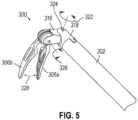
- FIGS. 2-5 show an exemplary alternative electrosurgical tool (300) that is substantially similar to tool (100) described above unless otherwise noted herein.
- tool (300) of the present example is generally configured and used similar to tool (100) of FIG. 1 and likewise includes an elongate shaft (302), an end effector (304) coupled to a distal end of shaft (302) and including first and second jaw members (306 a, 306 b), and a proximal housing portion (not shown) including a drive system (not shown) coupled to a proximal end of shaft (302).
- One or both jaw members (306a, 306b) may include an electrode operable to deliver RF energy to tissue.
- the proximal housing portion of tool (300) may be configured to operably couple to a tool driver of a robotic surgical system, or the proximal housing portion can be configured to be handheld and operated manually.
- Tool (300) includes a plurality of elongate actuatable drive members shown in the form of cables (308, 310, 312, 314) that are configured to be actuated to selectively cause opening of end effector (304), closing of end effector (304), and articulation of end effector (304) relative to shaft (302). Cables (308, 310, 312, 314) are attached to end effector (304) and extend along solid surfaces of guide channels in end effector (304), a distal clevis (316), and a proximal clevis (318), and from there extend proximally through shaft (302) to the proximal housing portion.
- cables (308, 310, 312, 314) that are configured to be actuated to selectively cause opening of end effector (304), closing of end effector (304), and articulation of end effector (304) relative to shaft (302). Cables (308, 310, 312, 314) are attached to end effector (304) and extend along solid surfaces of guide channels in end effector (304), a distal clevis (316
- tool (300) may also include one or more elongate conductive members shown in the form of wires (319) extending through shaft (302) to end effector (304) or other portions of tool (300).
- wires (319) may extend through shaft (302), proximal clevis (318), and distal clevis (316) to end effector (304).
- Such one or more wires (319) may be used for a variety of conductive purposes.
- tool (300) configured to operatively connect to a generator substantially similar to generator (118) for generating energy that can be used in connection with end effector (304).
- end effector (304) can be equipped with electrodes similar to electrodes (112 a, 112 b) described above.
- one or more wires (319) may be used to supply RF energy from the generator to the electrodes.
- various alternative uses for one or more wires (319) may be used as will be apparent to those of ordinary skill in the art in view of the teachings herein.
- distal clevis (316) is configured to rotate (322) relative to proximal clevis (318) about a pin (324) that defines a pitch axis. Rotation of distal clevis (316) relative to proximal clevis (318) is driven about the pitch axis in response to cable actuation.
- a drive system in response to control thereof (e.g., in response to motor force delivered thereto) pulls in identical lengths of third and fourth cables (312, 314) while releasing the same lengths of first and second cables (308, 310).
- Third and fourth cables (312, 314) apply forces to distal clevis (316) at moment arms defined by guide channels of third and fourth cables (312, 314) through distal clevis (316).
- the drive system in response to control thereof pulls in identical lengths of first and second cables (308, 310) while releasing the same lengths of third and fourth cables (312, 314).
- Proximal clevis (318) is fastened to the distal end of shaft (302) and extends distally therefrom.
- Proximal clevis (318) is generally configured to receive a portion of distal clevis (316) to permit rotation (322) of distal clevis (316) relative to shaft (302).
- proximal clevis (318) provides a point of connection between distal clevis (316) and shaft (302) to promote movement of distal clevis (316) relative to shaft (302).
- distal clevis (316) is fastened to proximal clevis (318) by pin (324), which defines the pitch axis.
- proximal clevis (318) is generally hollow such that cables (308, 310, 312, 314) and/or one or more wires (319) may extend through proximal clevis (318) to distal clevis (316) and/or end effector (304).
- a pin (320) in distal clevis (316) is perpendicular to pin (324) and defines a pivot or yaw axis, about which end effector (304) is configured to rotate (326) relative to distal clevis (316) and about which jaw members (306 a, 306 b) are configured to individually rotate (328) to open and close in response to cable actuation.
- first and second cables (308, 310) attach to first jaw member (306 a)
- third and fourth cables (312, 314) attach to second jaw member (306 b).
- first and second cables (308, 310) to first jaw member (306 a) is such that pulling in a length of one cable (308 or 310) while releasing the same length of the other cable (308 or 310) causes first jaw member (306 a) to rotate about pin (320).
- attachment of third and fourth cables (312, 314) to second jaw member (306 b) is such that pulling in a length of one cable (312 or 314) while releasing the same length of the other cable (312 or 314) causes second jaw member (306 b) to rotate about pin (320).
- a closure assembly of tool (300) thus includes cables (308, 310, 312, 314).
- Cables (308, 310, 312, 314) may be driven by one or more drive systems configured to selectively pull cables (308, 310, 312, 314) in proximal directions. It will be appreciated that such drive systems and other features and functions of surgical tool (300) may be configured in accordance with at least some of the teachings of U.S. Patent Publication No. 2019/0059987 . Exemplary embodiments of electrosurgical tools are further described in U.S. Pat. No. 9,119,657 entitled “Rotary Actuatable Closure Arrangement For Surgical End Effector” filed Jun. 28, 2012 and U.S. Pat. No. 8,771,270 entitled “Bipolar Cautery Instrument” filed Jul. 16, 2008 , which are hereby referred to herein in their entireties.
- sealing components may be desirable to prevent fluid ingress into the tools (100, 300) and to maintain insufflation of a patient's body cavity during a laparoscopic surgical procedure.
- Fluid ingress is generally undesirable in both robotic and hand-held applications of the instrument. For instance, fluid ingress in certain shaft portions of a surgical instrument can be particularly challenging to effectively clean and/or sterilize between surgical procedures. Moreover, fluid ingress can be indicative of an ineffectively sealed structure that is thus prone to leaking insufflation gas from an insufflated body cavity, which can reduce the efficiency of a surgical procedure.
- sealing components it is generally desirable to incorporate robust sealing components into various portions of electrosurgical tools (100, 300).
- sealing components will be described in greater detail below. However, it should be understood that various alternative configurations may be used without departing from the nature of the subject matter described herein. Additionally, although sealing components described herein are described in connection with electrosurgical tools (100, 300), it should be understood that such sealing components may be readily incorporated into various alternative surgical tools different from those described herein, such as surgical tools configured to grasp, cut, and/or staple tissue, where such tools may or may not be configured to apply RF energy to tissue.
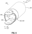
- FIG. 6 depicts an exemplary alternative proximal clevis (418) that is substantially similar to proximal clevis (318) described above.
- proximal clevis (418) can be readily incorporated into electrosurgical instrument (300) or other suitable surgical tools or instruments in lieu of proximal clevis (318) described above.
- electrosurgical instrument (300) or other suitable surgical tools or instruments in lieu of proximal clevis (318) described above.
- proximal clevis to refer to proximal clevis (418) is used herein, in some contexts the terms “coupling member,” “coupler,” or simply “clevis” may be used to refer to proximal clevis (418).
- proximal clevis (418) of the present example is configured to fasten to the distal end of shaft (302) and extend distally therefrom.
- proximal clevis (418) is generally configured to receive a portion of distal clevis (316) to permit rotation of distal clevis (316) relative to shaft (302).
- proximal clevis (418) provides a point of connection between distal clevis (316) and shaft (302) to promote movement of distal clevis (316) relative to shaft (302).
- proximal clevis (418) may be fastened to proximal clevis (418) by pin (324), which defines the pitch axis for rotation of distal clevis (316).
- proximal clevis (418) is generally hollow such that cables (308, 310, 312, 314) and/or one or more wires (319) may extend through proximal clevis (418) to distal clevis (316) and/or end effector (304).
- proximal clevis (418) may include certain structural features such as an annular base having an irregular shaped central opening.
- proximal clevis (418) may further include a pair of arms extending distally from the annular base to support pin (324) and distal clevis (316) as noted above.
- proximal clevis (418) of the present example includes a sealing feature (430) disposed within an interior portion of clevis (418).
- Sealing feature (430) is generally configured to provide a robust fluid tight seal at the distal end of shaft (302) to prevent fluid ingress (e.g., liquid and gas ingress) into shaft (302) from the exterior of shaft (302).
- sealing feature (430) is also generally configured to permit various components such as cables and/or wires to readily communicate with end effector (304) while maintaining the robust fluid seal noted above. As will be discussed in greater detail below, such communication with end effector (304) through sealing feature (430) may include movement of various components relative to sealing feature (430).
- sealing feature (430) includes certain features to promote movement of components relative thereto, while also maintaining a fluid tight seal. Although sealing feature (430) is discussed herein in connection with clevis (418), it should be understood that in other examples, sealing feature (430) can be readily incorporated into other components of tool (300) or other tools or instruments entirely.
- Sealing feature (430) of the present example is generally formed of a unitary compliant material overmolded into the interior of clevis (418). Use of a compliant material for sealing feature (430) is generally desirable to promote reduced wear. Use of a compliant material for sealing feature (430) is further desirable to provide flexion of sealing feature (430) while maintaining a sufficient seal with elongate components extending through sealing feature (430). In some examples, suitable compliant materials may include silicone or other similar materials. Although sealing feature (430) is described herein as being overmolded into proximal clevis (418), it should be understood that in some examples, sealing feature (430) may alternatively be molded separately and then attached to proximal clevis (418) by adhesive bonding, welding, and/or mechanical fastening.
- sealing feature (430) includes a seal body (432), and a plurality of projections, referred to herein as dimples, (440, 450) that extend axially relative to seal body (430).
- Seal body (432) generally extends transversely across the hollow interior defined by proximal clevis (418) to seal the interior of shaft (302) relative to the exterior of shaft (302).
- seal body (432) is generally continuous across the hollow interior of proximal clevis (418) to prevent the flow of fluid therethrough.
- Seal body (432) is generally configured to conform to the interior structure of proximal clevis (418).
- seal body (432) has a generally irregular shape that in some ways may be characterized as a multi-part structure with a distal sealing portion (434), a proximal sealing portion (436), and a gap (438) positioned therebetween.
- a structure of seal body (432) can be formed by at least a portion of proximal clevis (418) to provide additional structural rigidity to seal body (432).
- gap (438) may be formed by an internal structure, or structures, of proximal clevis (418) extending through the hollow interior of proximal clevis (418). During the overmolding process, such internal structure or structures may be surrounded with material forming seal body (432).
- seal body (432) may take on a variety of forms depending on the internal structure of proximal clevis (418). Suitable forms for seal body (432) and/or proximal clevis (418) may be configured in accordance with a variety of considerations such as the desired rigidity of seal body (432), ease of manufacturability, the desired surface area of contact between seal body (432) and proximal clevis (418), and/or etc.
- sealing feature (430) is configured to seal the interior of proximal clevis (418) while still permitting communication of various components with end effector (304).
- sealing feature (430) is configured to receive one or more components of tool (300) so that such components may pass through sealing feature (430) to end effector (304).
- sealing feature (430) includes dimples (440, 450) positioned to receive one or more components of tool (300) as will be described in greater detail below.
- each dimple (440, 450) extends both proximally within seal body (432) from distal sealing portion (434) and proximally from proximal sealing portion (436) of seal body (432). Accordingly, each dimple (440, 450) defines a generally cone-shaped protrusion through which certain portions of tool (300) may extend. Although each dimple (440, 450) is shown in the present example as projecting proximally, it should be understood that in other examples, one or more of dimples (440, 450) can alternatively project distally rather than proximally. In such configurations, the various structures of dimples (440, 450) described herein would be generally reversed from proximal to distal or distal to proximal.
- Each dimple (440, 450) includes a tapered receiving portion (442, 452) and a sealing portion (446, 456).
- Receiving portion (442, 452) of each dimple (440, 450) is defined by seal body (432) as a bore extending through seal body (432).
- the shape of receiving portion (442, 452) of each dimple (440, 450) is generally cylindrical and tapered, similar to a countersink.
- the taper angle of each receiving portion (442, 452) may be about 8°.
- Sealing portion (446, 456) of each dimple (440, 450) projects proximally from a corresponding receiving portion (442, 452). Additionally, each sealing portion (446, 456) projects proximally from a proximal face of seal body (432). As will be described in greater detail below, each sealing portion (446, 456) may be configured to bend or flex to maintain a fluid-tight seal in response to movement of one or more components of tool (300).
- Sealing portion (446, 456) of each dimple (440, 450) includes a sealing bore (448, 458) extending longitudinally through the entirety of sealing portion (446, 456).
- Each sealing bore (448, 458) is in communication with a corresponding receiving portion (442, 452) to define a continuous longitudinal path through the entirety of sealing feature (430). As will be described in greater detail below, this continuous longitudinal path generally permits various elongate components of tool (300) to pass through sealing feature (430).
- Each sealing bore (448, 458) of the present example defines a generally cylindrical shape.
- the particular diameter of each sealing bore (448, 458) generally corresponds to the diameter of a particular component of tool (300) as will be described in greater detail below.
- the diameter of each sealing bore (448, 458) is configured to provide a sealing fit with the particular component received therein.
- this sealing fit may be characterized as a compression or interference fit. Additionally, such a sealing fit may still be configured to provide at least some translation movement of corresponding components of tool (300) relative to each sealing portion (446, 456).
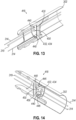
- FIGS. 11A through 12 show an exemplary process for forming each sealing bore (448, 458) during the overmolding process noted above.
- a first mold portion (472) of a mold (470) may include a core pin (474), pin, or other structure may be used to form through holes similar to each sealing bore (448, 458).
- the scale of each sealing bore (448, 458) could lead to core pin (474) or other similar structures contacting an opposing surface of a second mold portion (476) of mold (470) used in the overmolding process. This is a generally undesirable condition because it may result in damage to core pin (474) or other portions of mold (470).
- each core pin (474) of mold (470) is shortened such that only a portion of each sealing bore (448, 458) is formed by the respective core pin (474) itself. This may result in a proximal end portion of each sealing bore (448, 458) being capped or filled with a thin layer of excess material or web (460), where web (460) is formed integrally with the proximal end of the respective dimple (440, 450) and thus is disposed opposite to and in confronting relation with the free end of the respective core pin (474) during the overmolding process. Each web (460) may later be removed to form a proximal end opening of each sealing bore (448, 458) after the molding process is complete.
- each web (460) can be removed from the respective dimple (440, 450) using a variety of processes.
- a screw, hook, or other gripping feature (482) may be integrated into second mold portion (476) of mold (470) or a similar portion thereof that opposes the particular mold portion containing core pins (474) and at locations aligned with each dimple (440, 450) being formed such that a free end of each gripping feature projects toward and confronts a free end of the corresponding core pin (474).
- Such a screw, hook, or gripping feature may engage web (460) during molding , for example by being partially embedded within web (460), and subsequently tear web (460) along with any other excess material away from the respective formed dimple (440, 450) when the mold portions (472, 476) are separated from one another after molding is complete.
- web (460) may be formed with a thickness in an axial direction that is less than the wall thickness of the sealing portion (446, 456) in a radial direction.
- web (460) and any excess material can be removed from the proximal end portion of each formed dimple (440, 450) via piercing with a sharp object.
- web (460) and any excess material can be removed using a laser cutting process. Still other alternative processes for removal of web (460) and any excess materials will be apparent to those of ordinary skill in the art in view of the teachings herein.
- Dimples (440, 450) of the present example may be configured to receive differently sized components of tool (300).
- sealing feature (430) of the present example includes four cable dimples (440) configured to receive cables (308, 310, 312, 314), respectively, described above.
- sealing bore (448) of each cable dimple (440) has a diameter corresponding to the outer diameter of a corresponding cable (308, 310, 312, 314) such that sealing portion (446) of each cable dimple (440) is configured to sealingly engage a corresponding cable (308, 310, 312, 314).
- the particular number of cable dimples (440) corresponds to the particular number of cables (308, 310, 312, 314).
- sealing feature (430) may likewise include more or less cable dimples (440).
- Sealing feature (430) of the present example also includes two wire dimples (450) configured to receive respective wires (319) described above.
- sealing bore (458) of each wire dimple (450) has a diameter corresponding to the outer diameter of a corresponding wire (319) such that sealing portion (456) of each wire dimple (450) is configured to sealingly engage a corresponding wire (319).
- the particular number of each wire dimple (450) corresponds to the particular number of wires (319).
- sealing feature (430) may likewise include more or less wire dimples (450).
- dimples (440, 450) are described herein in the context of receiving either cables (308, 310, 312, 314) or wires (319), it should be understood that in other examples, dimples (440, 450) may be configured to readily receive other components of surgical tool (300).
- tool (300) may include tubes, cannulas, and/or etc. to provide various fluids to end effector (304).
- sealing feature (430) may likewise include structures similar to dimples (440, 450) for receiving such tubes, cannulas, and/or etc.
- each cable dimple (440) is configured to receive a corresponding cable (308, 310, 312, 314) such that the corresponding cable (308, 310, 312, 314) remains free to slide and/or translate longitudinally through and relative to sealing feature (430). Additionally, each cable dimple (440) is configured to transversely flex relative to a longitudinal axis of shaft (302) to accommodate transverse movement of cables (308, 310, 312, 314). Such transverse flexion may be desirable to accommodate articulation of end effector (304). For instance, in use, articulation of end effector (304) may result in some deflection of cables (308, 310, 312, 314) during the course of articulation.
- each cable dimple (440) With each cable dimple (440) flexing in response to such deflection of cables (308, 310, 312, 314), each cable dimple (440) is configured to maintain sealing engagement with each corresponding cable (308, 310, 312, 314) despite such deflection.
- wire dimples (450) may likewise support such deflection of wires (319) during articulation of end effector (304).
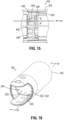
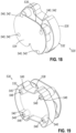
- FIG. 15 depicts another exemplary alternative proximal clevis (518) that is substantially similar to proximal clevis (318) described above.
- proximal clevis (518) can be readily incorporated into electrosurgical instrument (300) or other suitable surgical tools or instruments in lieu of proximal clevis (318) described above.
- proximal clevis (518) of the present example is configured to fasten to the distal end of shaft (302) and extend distally therefrom.
- proximal clevis (518) is generally configured to receive a portion of distal clevis (316) to permit rotation of distal clevis (316) relative to shaft (302).
- proximal clevis (518) provides a point of connection between distal clevis (316) and shaft (302) to promote movement of distal clevis (316) relative to shaft (302).
- distal clevis (316) may be fastened to proximal clevis (518) by pin (324), which defines the pitch axis for rotation of distal clevis (316).
- proximal clevis (518) is generally hollow such that cables (308, 310, 312, 314) and/or one or more wires (319) may extend through proximal clevis (518) to distal clevis (316) and/or end effector (304).
- proximal clevis (518) of the present example includes a sealing feature (530) disposed within an interior portion of clevis (518).
- Sealing feature (530) is generally configured to provide a robust fluid tight seal at the distal end of shaft (302) to prevent fluid ingress into shaft (302) from the exterior of shaft (302).
- sealing feature (530) is also generally configured to permit various components such as cables (308, 310, 312, 314) and/or wires (319) to readily communicate with end effector (304) while maintaining the robust fluid seal noted above.
- such communication with end effector (304) through sealing feature (530) may include movement of various components relative to sealing feature (530).
- sealing feature (530) includes certain components to promote movement of components relative thereto, while also maintaining a fluid tight seal. Although sealing feature (530) is discussed herein in connection with clevis (518), it should be understood that in other examples, sealing feature (530) can be readily incorporated into other components of tool (300) or other tools and/or instruments entirely.
- Sealing feature (530) of the present example is generally substantially similar to sealing feature (430) described above.
- sealing feature of the present example is formed of a unitary compliant material overmolded or otherwise fastened into the interior of proximal clevis (518).
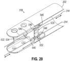
- Sealing feature (530) also includes a seal body (532), similar to seal body (432), defining a plurality of dimples (540).
- seal body (532) generally extends transversely across the hollow interior defined by proximal clevis (518) to seal the interior of shaft (302) relative to the exterior of shaft (302).
- seal body (532) of the present example has a generally irregular shape defining a distal sealing portion (534), a proximal sealing portion (536), and a gap (538) positioned therebetween.
- a structure of seal body (532) can be formed by at least a portion of proximal clevis (518) to provide additional structural rigidity to seal body (532).
- gap (538) may be formed by an internal structure, or structures, of proximal clevis (518) extending through the hollow interior of proximal clevis (518). During the overmolding process, such internal structure or structures may be surrounded with material forming seal body (532).
- sealing feature (530) of the present example includes dimples (540) positioned to receive one or more components of tool (300).
- each dimple (540) extends both proximally within seal body (532) from distal sealing portion (534) and proximally from proximal sealing portion (536) of seal body (532).
- each dimple (540) defines a generally cone-shaped protrusion through which certain portions of tool (300) may extend.
- each dimple (540) is shown in the present example as projecting proximally, it should be understood that in other examples, one or more of dimples (540) can alternatively project distally rather than proximally. In such configurations, the various structures of dimples (540) described herein would be generally reversed from proximal to distal or distal to proximal.
- each dimple (540) includes a tapered receiving portion (542) and sealing portion (546).
- Receiving portion (542) of each dimple (540) is defined by seal body (532) as a tapered bore extending through seal body (532).
- sealing portion (546) of each dimple (540) projects proximally from a corresponding receiving portion (542) and also projects proximally from a proximal face of seal body (532).
- Sealing portion (546) of each dimple (540) also includes a sealing bore (548), similar to sealing bore (448), extending longitudinally through the entirety of sealing portion (546).
- each sealing bore (548) of the present example defines a generally cylindrical shape generally corresponds to the diameter of a particular component of tool (300) therein to provide a sealing fit with such a component of tool (300).
- Dimples (540) of the present example may be configured to receive differently sized components of tool (300).
- sealing feature (530) of the present example includes four cable dimples (540) configured to receive cables (308, 310, 312, 314) described above.
- sealing bore (548) of each cable dimple (540) has a diameter corresponding to the outer diameter of a corresponding cable (308, 310, 312, 314) such that sealing portion (546) of each cable dimple (540) is configured to sealingly engage a corresponding cable (308, 310, 312, 314).
- the particular number of each cable dimple (540) corresponds to the particular number of cables (308, 310, 312, 314).
- sealing feature (530) may likewise include more or less cable dimples (540).
- sealing feature (530) of the present example omits structures similar to wire dimples (450).
- sealing feature (540) of the present example is configured for use in version of tool (300) without one or more wires (319), or versions of tool (300) where wires (319) are present, but do not extend all the way to end effector (304).
- dimples (540) are described herein in the context of receiving cables (308, 310, 312, 314), it should be understood that in other examples, dimples (540) may be configured to readily receive other components.
- tool (300) may include tubes, cannulas, and/or etc. to provide various fluids to end effector (304).
- sealing feature (530) may likewise include structures similar to dimples (540) for receiving such tubes, cannulas, and/or etc.
- each cable dimple (540) is configured to receive a corresponding cable (308, 310, 312, 314) such that the corresponding cable (308, 310, 312, 314) remains free to slide and/or translate relative to sealing feature (530). Additionally, each cable dimple (540) is configured to transversely flex to accommodate transverse movement of cables (308, 310, 312, 314). Such transverse flexion may be desirable to accommodate articulation of end effector (304). For instance, in use, articulation of end effector (304) may result in some deflection of cables (308, 310, 312, 314) during the course of articulation.
- each cable dimple (540) With each cable dimple (540) flexing in response to such deflection of cables (308, 310, 312, 314), each cable dimple (540) is configured to maintain sealing engagement with each corresponding cable (308, 310, 312, 314) despite such deflection.
- Versions of the devices described above may have application in conventional medical treatments and procedures conducted by a medical professional, as well as application in robotic-assisted medical treatments and procedures.
- various teachings herein may be readily incorporated into a robotic surgical system such as the DAVINCI TM system by Intuitive Surgical, Inc., of Sunnyvale, California.
- Versions of the devices described above may be designed to be disposed of after a single use, or they can be designed to be used multiple times. Versions may, in either or both cases, be reconditioned for reuse after at least one use. Reconditioning may include any combination of the steps of disassembly of the device, followed by cleaning or replacement of particular pieces, and subsequent reassembly. In particular, some versions of the device may be disassembled, and any number of the particular pieces or parts of the device may be selectively replaced or removed in any combination. Upon cleaning and/or replacement of particular parts, some versions of the device may be reassembled for subsequent use either at a reconditioning facility, or by a user immediately prior to a procedure.
- reconditioning of a device may utilize a variety of techniques for disassembly, cleaning/replacement, and reassembly. Use of such techniques, and the resulting reconditioned device, are all within the scope of the present application.
- versions described herein may be sterilized before and/or after a procedure.
- the device is placed in a closed and sealed container, such as a plastic or TYVEK bag.
- the container and device may then be placed in a field of radiation that can penetrate the container, such as gamma radiation, x-rays, or high-energy electrons.
- the radiation may kill bacteria on the device and in the container.
- the sterilized device may then be stored in the sterile container for later use.
- a device may also be sterilized using any other technique known in the art, including but not limited to beta or gamma radiation, ethylene oxide, or steam.
Landscapes
- Engineering & Computer Science (AREA)
- Health & Medical Sciences (AREA)
- Surgery (AREA)
- Life Sciences & Earth Sciences (AREA)
- Manufacturing & Machinery (AREA)
- Mechanical Engineering (AREA)
- Plasma & Fusion (AREA)
- Otolaryngology (AREA)
- Nuclear Medicine, Radiotherapy & Molecular Imaging (AREA)
- Physics & Mathematics (AREA)
- Biomedical Technology (AREA)
- Heart & Thoracic Surgery (AREA)
- Medical Informatics (AREA)
- Molecular Biology (AREA)
- Animal Behavior & Ethology (AREA)
- General Health & Medical Sciences (AREA)
- Public Health (AREA)
- Veterinary Medicine (AREA)
- Surgical Instruments (AREA)
Claims (16)
- Chirurgische Einrichtung (100, 300), umfassend(a) einen Körper (110);(b) eine Wellenanordnung (102,302), die sich von dem Körper distal erstreckt, wobei die Wellenanordnung ein distales Ende einschließt;(c) einen Endeffektor (104);(d) ein Kopplungselement (418), das an dem distalen Ende der Wellenanordnung eingerichtet ist, um den Endeffektor mit der Wellenanordnung bewegbar zu koppeln; und(e) ein Dichtungsmerkmal (430), das mit dem Kopplungselement in Eingriff steht, wobei das Dichtungsmerkmal einen Dichtungskörper (432) und eine Vielzahl von Vorsprüngen (440, 450) einschließt, die sich von dem Dichtungskörper erstreckt, wobei jeder Vorsprung der Vielzahl von Vorsprüngen konfiguriert ist, um ein jeweiliges längliches Element, das mit dem Endeffektor verknüpft ist, dahindurch gleitend aufzunehmen,dadurch gekennzeichnet, dass das Dichtungsmerkmal in die Struktur des Kopplungselements integriert ist.
- Einrichtung nach Anspruch 1, wobei jeder Vorsprung einen Aufnahmeabschnitt (442, 452) und einen dichtenden Abschnitt (446, 456) definiert, wobei der dichtende Abschnitt konfiguriert ist, um mit dem länglichen Element dichtend in Eingriff zu stehen.
- Einrichtung nach Anspruch 2, wobei der dichtende Abschnitt konfiguriert ist, um sich als Reaktion auf eine Querbewegung des länglichen Elements relativ zu einer Längsachse der Wellenanordnung zu biegen.
- Einrichtung nach Anspruch 2, wobei der dichtende Abschnitt konfiguriert ist, um sich als Reaktion auf die Querbewegung des länglichen Elements relativ zu einer Längsachse der Wellenanordnung zu biegen, während der dichtende Eingriff mit dem länglichen Element aufrechterhalten wird.
- Einrichtung nach Anspruch 1, wobei der dichtende Abschnitt eine Dichtungsbohrung (448, 458) definiert, wobei die Dichtungsbohrung einen Durchmesser definiert, der ungefähr gleich einem Durchmesser des länglichen Elements ist.
- Einrichtung nach Anspruch 1, wobei der Aufnahmeabschnitt eine konische Bohrung definiert, die sich dahindurch erstreckt, die mit mindestens einem Abschnitt des dichtenden Abschnitts in Kommunikation steht.
- Einrichtung nach Anspruch 1, ferner umfassend eine Vielzahl von Kabeln (308, 310, 312, 314), die sich von dem Körper durch die Wellenanordnung hindurch zu dem Endeffektor erstreckt, wobei jedes Kabel relativ zu dem Körper bewegbar ist, um eine Bewegung des Endeffektors anzutreiben, wobei jeder Vorsprung der Vielzahl von Vorsprüngen konfiguriert ist, um ein entsprechendes Kabel verschiebbar aufzunehmen, um die Bewegung des Endeffektors über ein oder mehrere Kabel der Vielzahl von Kabeln zu ermöglichen.
- Einrichtung nach Anspruch 7, wobei jeder Vorsprung konfiguriert ist, um sich als Reaktion auf eine Querdurchbiegung eines entsprechenden Kabels über die Bewegung des Endeffektors quer zu biegen.
- Einrichtung nach Anspruch 1, ferner umfassend eine Vielzahl von Kabeln, die konfiguriert ist, um den Endeffektor anzutreiben, und einen oder mehrere Drähte (319), die konfiguriert sind, um HF-Energie an den Endeffektor zu kommunizieren, wobei die Vielzahl von Kabeln und der eine oder die mehreren Drähte sich von dem Körper durch die Wellenanordnung hindurch zu dem Endeffektor erstrecken, wobei ein oder mehrere Vorsprünge der Vielzahl von Vorsprüngen konfiguriert sind, ein Kabel der Vielzahl von Kabeln verschiebbar aufzunehmen, wobei ein oder mehrere Vorsprünge der Vielzahl von Vorsprüngen (450) konfiguriert sind, um einen Draht der einen oder mehreren Drähte verschiebbar aufzunehmen.
- Einrichtung nach Anspruch 9, wobei jeder Vorsprung der Vielzahl von Vorsprüngen konfiguriert ist, um sich als Reaktion auf die Querbewegung eines jeweiligen Kabels oder Drahts zu biegen.
- Einrichtung nach Anspruch 1, wobei sich jeder Vorsprung der Vielzahl von Vorsprüngen von dem Dichtungskörper proximal erstreckt.
- Einrichtung nach Anspruch 1, wobei das Dichtungsmerkmal ein nachgiebiges Material umfasst.
- Einrichtung nach Anspruch 12, wobei das Dichtungsmerkmal Silikon umfasst.
- Einrichtung nach Anspruch 1, wobei der Dichtungskörper einen distalen Abschnitt und einen proximalen Abschnitt einschließt, wobei zwischen dem proximalen Abschnitt und dem distalen Abschnitt ein Spalt definiert ist, wobei sich ein Abschnitt des Kopplungselements durch den Spalt hindurch zwischen dem proximalen Abschnitt und dem distalen Abschnitt erstreckt.
- Verfahren zum Umspritzen eines Dichtungsmerkmals (430) auf einen Gabelkopf (418), das für eine Verwendung mit einem chirurgischen Instrument (100, 300) konfiguriert ist, das Verfahren umfassend:(a) Positionieren des Gabelkopfs innerhalb einer Form (470), die einen ersten Formabschnitt (472) und einen zweiten Formabschnitt (476) aufweist, wobei der erste Formabschnitt einen Stift (474) einschließt, der ein freies Ende aufweist, das sich zu einer gegenüberliegenden Oberfläche des zweiten Formabschnitts hin erstreckt und von dieser beabstandet ist;(b) Leiten von Material in die Form und um den Stift herum, wobei dadurch das Dichtungsmerkmal aus dem Material derart ausgebildet wird, dass der Stift eine dichtende Bohrung des Dichtungsmerkmals definiert, wobei das Dichtungsmerkmal eine Schicht des Materials zwischen dem freien Ende des Stifts und der gegenüberliegenden Oberfläche des zweiten Formabschnitts derart einschließt, dass sich die Materialschicht an einem Ende der dichtende Bohrung befindet;(c) nachdem das Material ausgehärtet ist, Entfernen der Materialschicht von dem Dichtungsmerkmal, um eine Öffnung zu der dichtende Bohrung auszubilden; und(d) Koppeln des Gabelkopfs, der das Dichtungsmerkmal aufweist, mit einem distalen Ende einer Wellenanordnung eines chirurgischen Instruments.
- Verfahren nach Anspruch 15, wobei der zweite Formabschnitt einen Greifvorsprung (482) einschließt, der sich zu dem freien Ende des Stifts des ersten Formabschnitts hin erstreckt und diesem gegenüberliegt, wobei der Schritt des Entfernens der Materialschicht durch Trennen des ersten Formabschnitts von dem zweiten Formabschnitt derart durchgeführt wird, dass der Greifvorsprung die Materialschicht von dem Dichtungsmerkmal wegreißt.
Applications Claiming Priority (2)
| Application Number | Priority Date | Filing Date | Title |
|---|---|---|---|
| US17/129,013 US20220192732A1 (en) | 2020-12-21 | 2020-12-21 | Seal for surgical instrument |
| PCT/IB2021/062030 WO2022137086A1 (en) | 2020-12-21 | 2021-12-20 | Seal for surgical instrument |
Publications (3)
| Publication Number | Publication Date |
|---|---|
| EP4087508A1 EP4087508A1 (de) | 2022-11-16 |
| EP4087508C0 EP4087508C0 (de) | 2024-12-18 |
| EP4087508B1 true EP4087508B1 (de) | 2024-12-18 |
Family
ID=79170823
Family Applications (1)
| Application Number | Title | Priority Date | Filing Date |
|---|---|---|---|
| EP21835412.4A Active EP4087508B1 (de) | 2020-12-21 | 2021-12-20 | Dichtung für chirurgisches instrument |
Country Status (6)
| Country | Link |
|---|---|
| US (1) | US20220192732A1 (de) |
| EP (1) | EP4087508B1 (de) |
| JP (1) | JP7767432B2 (de) |
| KR (1) | KR20230123483A (de) |
| CN (1) | CN116648205A (de) |
| WO (1) | WO2022137086A1 (de) |
Families Citing this family (2)
| Publication number | Priority date | Publication date | Assignee | Title |
|---|---|---|---|---|
| GB2609637B (en) * | 2021-08-10 | 2023-10-04 | Gyrus Medical Ltd | Surgical device seal |
| WO2025186528A1 (en) * | 2024-03-08 | 2025-09-12 | Cmr Surgical Limited | Resilient barrier for inclusion within a robotic surgical instrument |
Family Cites Families (16)
| Publication number | Priority date | Publication date | Assignee | Title |
|---|---|---|---|---|
| DE2748057C3 (de) * | 1977-10-26 | 1980-04-30 | Machida Endoscope Co., Ltd., Tokio | Endoskopisches Auszugs- oder Schneidgerät |
| CA2442681C (en) * | 2001-04-06 | 2011-03-22 | Sherwood Services Ag | Vessel sealer and divider |
| US7354440B2 (en) | 2001-10-22 | 2008-04-08 | Surgrx, Inc. | Electrosurgical instrument and method of use |
| US7189233B2 (en) | 2001-10-22 | 2007-03-13 | Surgrx, Inc. | Electrosurgical instrument |
| US9204923B2 (en) * | 2008-07-16 | 2015-12-08 | Intuitive Surgical Operations, Inc. | Medical instrument electronically energized using drive cables |
| US8771270B2 (en) | 2008-07-16 | 2014-07-08 | Intuitive Surgical Operations, Inc. | Bipolar cautery instrument |
| US10441345B2 (en) | 2009-10-09 | 2019-10-15 | Ethicon Llc | Surgical generator for ultrasonic and electrosurgical devices |
| US9161803B2 (en) | 2010-11-05 | 2015-10-20 | Ethicon Endo-Surgery, Inc. | Motor driven electrosurgical device with mechanical and electrical feedback |
| US9119657B2 (en) | 2012-06-28 | 2015-09-01 | Ethicon Endo-Surgery, Inc. | Rotary actuatable closure arrangement for surgical end effector |
| US9802033B2 (en) | 2014-01-28 | 2017-10-31 | Ethicon Llc | Surgical devices having controlled tissue cutting and sealing |
| WO2018013217A1 (en) * | 2016-07-14 | 2018-01-18 | Intuitive Surgical Operations, Inc. | Instruments with electrically isolated components, related systems and methods |
| US20190059987A1 (en) | 2017-08-29 | 2019-02-28 | Ethicon Llc | Methods, systems, and devices for controlling electrosurgical tools |
| US10881391B2 (en) * | 2017-11-03 | 2021-01-05 | Covidien Lp | Sealing pack assembly for use with endoscopic stitching device |
| JP6741731B2 (ja) * | 2018-08-28 | 2020-08-19 | 株式会社メディカロイド | ロボット手術器具およびその組み立て方法 |
| JP6878622B2 (ja) * | 2018-08-28 | 2021-05-26 | 株式会社メディカロイド | ロボット手術器具 |
| US11717364B2 (en) * | 2018-12-31 | 2023-08-08 | Asensus Surgical Us, Inc. | Articulating surgical instrument |
-
2020
- 2020-12-21 US US17/129,013 patent/US20220192732A1/en active Pending
-
2021
- 2021-12-20 CN CN202180085538.5A patent/CN116648205A/zh active Pending
- 2021-12-20 EP EP21835412.4A patent/EP4087508B1/de active Active
- 2021-12-20 KR KR1020237023337A patent/KR20230123483A/ko active Pending
- 2021-12-20 WO PCT/IB2021/062030 patent/WO2022137086A1/en not_active Ceased
- 2021-12-20 JP JP2023537563A patent/JP7767432B2/ja active Active
Also Published As
| Publication number | Publication date |
|---|---|
| JP2024501234A (ja) | 2024-01-11 |
| JP7767432B2 (ja) | 2025-11-11 |
| CN116648205A (zh) | 2023-08-25 |
| EP4087508C0 (de) | 2024-12-18 |
| EP4087508A1 (de) | 2022-11-16 |
| KR20230123483A (ko) | 2023-08-23 |
| US20220192732A1 (en) | 2022-06-23 |
| WO2022137086A1 (en) | 2022-06-30 |
Similar Documents
| Publication | Publication Date | Title |
|---|---|---|
| US11602394B2 (en) | Electrosurgical device with disposable shaft having modular subassembly | |
| US10568684B2 (en) | Electrosurgical device with disposable shaft having clamshell coupling | |
| EP3629952B1 (de) | Kombination eines ultraschall- und elektrochirurgischen instrumentes mit einem ultraschall-wellenleiter und einem distalen umformenden element | |
| US10478186B2 (en) | Electrosurgical device with disposable shaft having rack and pinion drive | |
| US9980777B2 (en) | Electrosurgical device with disposable shaft having translating gear and snap fit | |
| KR102149652B1 (ko) | 관절운동식 엔드 이펙터를 갖는 로봇 초음파 수술 장치 | |
| US11311344B2 (en) | Electrosurgical device with drum-driven articulation | |
| US20140364852A1 (en) | Surgical instrument with modular motor | |
| CN105764568A (zh) | 具有压电密封头的超声吻合器械 | |
| US20140371737A1 (en) | Surgical instrument with articulation indicator | |
| EP4087508B1 (de) | Dichtung für chirurgisches instrument | |
| US10646270B2 (en) | Surgical instrument with articulating portion |
Legal Events
| Date | Code | Title | Description |
|---|---|---|---|
| STAA | Information on the status of an ep patent application or granted ep patent |
Free format text: STATUS: UNKNOWN |
|
| STAA | Information on the status of an ep patent application or granted ep patent |
Free format text: STATUS: THE INTERNATIONAL PUBLICATION HAS BEEN MADE |
|
| PUAI | Public reference made under article 153(3) epc to a published international application that has entered the european phase |
Free format text: ORIGINAL CODE: 0009012 |
|
| STAA | Information on the status of an ep patent application or granted ep patent |
Free format text: STATUS: REQUEST FOR EXAMINATION WAS MADE |
|
| 17P | Request for examination filed |
Effective date: 20220809 |
|
| AK | Designated contracting states |
Kind code of ref document: A1 Designated state(s): AL AT BE BG CH CY CZ DE DK EE ES FI FR GB GR HR HU IE IS IT LI LT LU LV MC MK MT NL NO PL PT RO RS SE SI SK SM TR |
|
| DAV | Request for validation of the european patent (deleted) | ||
| DAX | Request for extension of the european patent (deleted) | ||
| GRAP | Despatch of communication of intention to grant a patent |
Free format text: ORIGINAL CODE: EPIDOSNIGR1 |
|
| STAA | Information on the status of an ep patent application or granted ep patent |
Free format text: STATUS: GRANT OF PATENT IS INTENDED |
|
| INTG | Intention to grant announced |
Effective date: 20240617 |
|
| GRAJ | Information related to disapproval of communication of intention to grant by the applicant or resumption of examination proceedings by the epo deleted |
Free format text: ORIGINAL CODE: EPIDOSDIGR1 |
|
| STAA | Information on the status of an ep patent application or granted ep patent |
Free format text: STATUS: REQUEST FOR EXAMINATION WAS MADE |
|
| GRAP | Despatch of communication of intention to grant a patent |
Free format text: ORIGINAL CODE: EPIDOSNIGR1 |
|
| STAA | Information on the status of an ep patent application or granted ep patent |
Free format text: STATUS: GRANT OF PATENT IS INTENDED |
|
| INTC | Intention to grant announced (deleted) | ||
| INTG | Intention to grant announced |
Effective date: 20240814 |
|
| GRAS | Grant fee paid |
Free format text: ORIGINAL CODE: EPIDOSNIGR3 |
|
| GRAA | (expected) grant |
Free format text: ORIGINAL CODE: 0009210 |
|
| STAA | Information on the status of an ep patent application or granted ep patent |
Free format text: STATUS: THE PATENT HAS BEEN GRANTED |
|
| AK | Designated contracting states |
Kind code of ref document: B1 Designated state(s): AL AT BE BG CH CY CZ DE DK EE ES FI FR GB GR HR HU IE IS IT LI LT LU LV MC MK MT NL NO PL PT RO RS SE SI SK SM TR |
|
| REG | Reference to a national code |
Ref country code: CH Ref legal event code: EP |
|
| REG | Reference to a national code |
Ref country code: DE Ref legal event code: R096 Ref document number: 602021023687 Country of ref document: DE |
|
| REG | Reference to a national code |
Ref country code: IE Ref legal event code: FG4D |
|
| U01 | Request for unitary effect filed |
Effective date: 20250110 |
|
| U07 | Unitary effect registered |
Designated state(s): AT BE BG DE DK EE FI FR IT LT LU LV MT NL PT RO SE SI Effective date: 20250120 |
|
| U20 | Renewal fee for the european patent with unitary effect paid |
Year of fee payment: 4 Effective date: 20250124 |
|
| PG25 | Lapsed in a contracting state [announced via postgrant information from national office to epo] |
Ref country code: HR Free format text: LAPSE BECAUSE OF FAILURE TO SUBMIT A TRANSLATION OF THE DESCRIPTION OR TO PAY THE FEE WITHIN THE PRESCRIBED TIME-LIMIT Effective date: 20241218 |
|
| PG25 | Lapsed in a contracting state [announced via postgrant information from national office to epo] |
Ref country code: NO Free format text: LAPSE BECAUSE OF FAILURE TO SUBMIT A TRANSLATION OF THE DESCRIPTION OR TO PAY THE FEE WITHIN THE PRESCRIBED TIME-LIMIT Effective date: 20250318 |
|
| PG25 | Lapsed in a contracting state [announced via postgrant information from national office to epo] |
Ref country code: GR Free format text: LAPSE BECAUSE OF FAILURE TO SUBMIT A TRANSLATION OF THE DESCRIPTION OR TO PAY THE FEE WITHIN THE PRESCRIBED TIME-LIMIT Effective date: 20250319 |
|
| PG25 | Lapsed in a contracting state [announced via postgrant information from national office to epo] |
Ref country code: RS Free format text: LAPSE BECAUSE OF FAILURE TO SUBMIT A TRANSLATION OF THE DESCRIPTION OR TO PAY THE FEE WITHIN THE PRESCRIBED TIME-LIMIT Effective date: 20250318 |
|
| PG25 | Lapsed in a contracting state [announced via postgrant information from national office to epo] |
Ref country code: SM Free format text: LAPSE BECAUSE OF FAILURE TO SUBMIT A TRANSLATION OF THE DESCRIPTION OR TO PAY THE FEE WITHIN THE PRESCRIBED TIME-LIMIT Effective date: 20241218 |
|
| PG25 | Lapsed in a contracting state [announced via postgrant information from national office to epo] |
Ref country code: PL Free format text: LAPSE BECAUSE OF FAILURE TO SUBMIT A TRANSLATION OF THE DESCRIPTION OR TO PAY THE FEE WITHIN THE PRESCRIBED TIME-LIMIT Effective date: 20241218 |
|
| PG25 | Lapsed in a contracting state [announced via postgrant information from national office to epo] |
Ref country code: ES Free format text: LAPSE BECAUSE OF FAILURE TO SUBMIT A TRANSLATION OF THE DESCRIPTION OR TO PAY THE FEE WITHIN THE PRESCRIBED TIME-LIMIT Effective date: 20241218 |
|
| PG25 | Lapsed in a contracting state [announced via postgrant information from national office to epo] |
Ref country code: IS Free format text: LAPSE BECAUSE OF FAILURE TO SUBMIT A TRANSLATION OF THE DESCRIPTION OR TO PAY THE FEE WITHIN THE PRESCRIBED TIME-LIMIT Effective date: 20250418 |
|
| PG25 | Lapsed in a contracting state [announced via postgrant information from national office to epo] |
Ref country code: SK Free format text: LAPSE BECAUSE OF FAILURE TO SUBMIT A TRANSLATION OF THE DESCRIPTION OR TO PAY THE FEE WITHIN THE PRESCRIBED TIME-LIMIT Effective date: 20241218 |
|
| PG25 | Lapsed in a contracting state [announced via postgrant information from national office to epo] |
Ref country code: CZ Free format text: LAPSE BECAUSE OF FAILURE TO SUBMIT A TRANSLATION OF THE DESCRIPTION OR TO PAY THE FEE WITHIN THE PRESCRIBED TIME-LIMIT Effective date: 20241218 |
|
| REG | Reference to a national code |
Ref country code: CH Ref legal event code: PL |
|
| PG25 | Lapsed in a contracting state [announced via postgrant information from national office to epo] |
Ref country code: MC Free format text: LAPSE BECAUSE OF FAILURE TO SUBMIT A TRANSLATION OF THE DESCRIPTION OR TO PAY THE FEE WITHIN THE PRESCRIBED TIME-LIMIT Effective date: 20241218 |
|
| PG25 | Lapsed in a contracting state [announced via postgrant information from national office to epo] |
Ref country code: CH Free format text: LAPSE BECAUSE OF NON-PAYMENT OF DUE FEES Effective date: 20241231 |
|
| PG25 | Lapsed in a contracting state [announced via postgrant information from national office to epo] |
Ref country code: IE Free format text: LAPSE BECAUSE OF NON-PAYMENT OF DUE FEES Effective date: 20241220 |
|
| PLBE | No opposition filed within time limit |
Free format text: ORIGINAL CODE: 0009261 |
|
| STAA | Information on the status of an ep patent application or granted ep patent |
Free format text: STATUS: NO OPPOSITION FILED WITHIN TIME LIMIT |
|
| 26N | No opposition filed |
Effective date: 20250919 |