EP4087271A1 - Verfahren und vorrichtung zur dienstübertragung, sendeende und speichermedium - Google Patents
Verfahren und vorrichtung zur dienstübertragung, sendeende und speichermedium Download PDFInfo
- Publication number
- EP4087271A1 EP4087271A1 EP21796980.7A EP21796980A EP4087271A1 EP 4087271 A1 EP4087271 A1 EP 4087271A1 EP 21796980 A EP21796980 A EP 21796980A EP 4087271 A1 EP4087271 A1 EP 4087271A1
- Authority
- EP
- European Patent Office
- Prior art keywords
- transmission
- entity
- service
- preempted
- transmission entity
- Prior art date
- Legal status (The legal status is an assumption and is not a legal conclusion. Google has not performed a legal analysis and makes no representation as to the accuracy of the status listed.)
- Pending
Links
Images

Classifications
-
- H—ELECTRICITY
- H04—ELECTRIC COMMUNICATION TECHNIQUE
- H04Q—SELECTING
- H04Q11/00—Selecting arrangements for multiplex systems
- H04Q11/0001—Selecting arrangements for multiplex systems using optical switching
- H04Q11/0062—Network aspects
-
- H—ELECTRICITY
- H04—ELECTRIC COMMUNICATION TECHNIQUE
- H04Q—SELECTING
- H04Q11/00—Selecting arrangements for multiplex systems
- H04Q11/0001—Selecting arrangements for multiplex systems using optical switching
- H04Q11/0062—Network aspects
- H04Q11/0067—Provisions for optical access or distribution networks, e.g. Gigabit Ethernet Passive Optical Network (GE-PON), ATM-based Passive Optical Network (A-PON), PON-Ring
-
- H—ELECTRICITY
- H04—ELECTRIC COMMUNICATION TECHNIQUE
- H04B—TRANSMISSION
- H04B10/00—Transmission systems employing electromagnetic waves other than radio-waves, e.g. infrared, visible or ultraviolet light, or employing corpuscular radiation, e.g. quantum communication
- H04B10/40—Transceivers
-
- H—ELECTRICITY
- H04—ELECTRIC COMMUNICATION TECHNIQUE
- H04B—TRANSMISSION
- H04B10/00—Transmission systems employing electromagnetic waves other than radio-waves, e.g. infrared, visible or ultraviolet light, or employing corpuscular radiation, e.g. quantum communication
- H04B10/50—Transmitters
-
- H—ELECTRICITY
- H04—ELECTRIC COMMUNICATION TECHNIQUE
- H04B—TRANSMISSION
- H04B10/00—Transmission systems employing electromagnetic waves other than radio-waves, e.g. infrared, visible or ultraviolet light, or employing corpuscular radiation, e.g. quantum communication
- H04B10/60—Receivers
-
- H—ELECTRICITY
- H04—ELECTRIC COMMUNICATION TECHNIQUE
- H04Q—SELECTING
- H04Q11/00—Selecting arrangements for multiplex systems
- H04Q11/0001—Selecting arrangements for multiplex systems using optical switching
- H04Q11/0062—Network aspects
- H04Q2011/0064—Arbitration, scheduling or medium access control aspects
-
- H—ELECTRICITY
- H04—ELECTRIC COMMUNICATION TECHNIQUE
- H04Q—SELECTING
- H04Q11/00—Selecting arrangements for multiplex systems
- H04Q11/0001—Selecting arrangements for multiplex systems using optical switching
- H04Q11/0062—Network aspects
- H04Q2011/0086—Network resource allocation, dimensioning or optimisation
-
- H—ELECTRICITY
- H04—ELECTRIC COMMUNICATION TECHNIQUE
- H04Q—SELECTING
- H04Q2213/00—Indexing scheme relating to selecting arrangements in general and for multiplex systems
- H04Q2213/1301—Optical transmission, optical switches
Definitions
- Embodiments of the present application relate to, but not limited to, the technical field of communication, and more particularly, to a service transmission method and apparatus, a sender and a storage medium.
- a Passive Optical Network is a typical passive optical network.
- a PON system usually comprises an Optical Line Terminal (OLT) at the local side, an Optical Network Unit (ONU) at the user side and an Optical Distribution Network (ODN).
- OLT Optical Line Terminal
- ONU Optical Network Unit
- ODN Optical Distribution Network
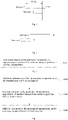
- a service 1 has a higher priority than a service 2.
- the service 2 is being sent. At this time, the service 2 has to wait to be sent before the service 1 is sent.
- this transmission mode causes the transmission of the high-priority service to have a certain delay, and the magnitude of the delay is shown in Fig. 1 .
- Embodiments of the present application provide a service transmission method and apparatus, a sender and a storage medium to reduce a transmission delay of a time-sensitive service.
- an embodiment provides a service transmission method applied to a sender.
- the method includes a following step: preempting, by one transmission entity, a transmission opportunity of another transmission entity to perform service transmission.
- an embodiment further provides a service transmission apparatus arranged at a sender.
- the apparatus includes: a first control module configured to control one transmission entity to preempt a transmission opportunity of another transmission entity to perform service transmission.
- an embodiment further provides a sender, including: a controller; a transmission entity configured to transmit a service; and a memory configured to store one or more programs which, when executed by the controller, cause the controller to implement the service transmission method as described above.
- an embodiment further provides a storage medium storing a computer program which, when executed by a controller, causes the controller to implement the service transmission method as described above.
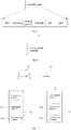
- Fig. 3 is a flowchart of a service transmission method provided in an embodiment of the present application. This embodiment is applied to service transmission of a Passive Optical Network (PON) system to reduce a transmission delay of a time-sensitive service.
- the method may be executed by a service transmission apparatus which may be implemented by means of software and/or hardware, and is generally integrated in a sender which may be either an Optical Network Unit (ONU) or an Optical Line Terminal (OLT).
- ONU Optical Network Unit
- OLT Optical Line Terminal
- the sender is an ONU
- a receiver is an OLT
- the sender is an OLT
- the receiver is an ONU
- a transmission direction from the ONU to the OLT is referred to as an uplink direction
- a transmission direction from the OLT to the ONU is referred to as a downlink direction.
- the uplink direction is similar to the downlink direction in service transmission process.
- the uplink direction is taken as an example, and is applied to a same ONU
- the method includes a following step of S110: At S110, one transmission entity preempts a transmission opportunity of another transmission entity to perform service transmission.
- a service transmission process in this embodiment may be implemented in an active way or a passive way, where the active way is that the transmission entity actively preempts the transmission opportunity to perform service transmission, and the passive way is that the transmission entity preempts the transmission opportunity to perform service transmission under control, for example, a certain one transmission entity preempts a transmission opportunity of another transmission entity under the control of a controller.
- the passive way is taken as an example.
- a transmission entity is an apparatus used to transmit a service received by a sender to a receiver.
- a transmission opportunity is an opportunity for the transmission entity to perform service transmission, and the transmission entity performs service transmission when having the transmission opportunity.
- the transmission opportunity of the transmission entity may be obtained by preemption, especially when a Time Sensitive Network (TSN) service is transmitted, a transmission delay of the TSN service may be reduced by preempting a transmission opportunity.
- TSN Time Sensitive Network
- whether a transmission entity can be preempted may be determined according to identification information of the transmission entity. For example, when a certain transmission entity is identified as being allowed to be preempted, it means that all transmission opportunities of the transmission entity can be preempted. Whether a transmission opportunity can be preempted may be determined according to identification information of the transmission opportunity. For example, when a certain transmission opportunity is identified as being allowed to be preempted, it means that the transmission opportunity can be preempted. Generally, the identification information of the transmission entity may be set according to a priority of the transmission entity, for example, a high-priority transmission entity may preempt a low-priority transmission entity.
- Transmission entities with different priorities may correspond to services with different priorities.
- the priorities of the services may be determined by the user side, and then sent to the sender through corresponding ports of the sender. Priorities of corresponding services are obtained by the sender according to different ports, and may also be determined by the sender. For example, the user side sends services to the sender through a same port in the form of data packets, and the sender determines priorities of all the services by parsing the data packets. After receiving the services, the sender may allocate the services to corresponding transmission entities according to the priorities of the services, and the transmission entities send the services to the receiver.
- a high-priority service may be allocated to a high-priority transmission entity, and a low-priority service may be allocated to a low-priority transmission entity.
- a transmission entity A is identified as being allowed to preempt, and a transmission entity B is identified as being allowed to be preempted.
- the transmission entity A may be controlled to preempt a transmission opportunity of the transmission entity B, so that the transmission entity A may preemptively transmit the high-priority TSN service, thereby reducing a transmission delay of the high-priority service.
- An embodiment of the present application provides a service transmission method.
- the method includes following step: preempting, by one transmission entity, a transmission opportunity of another transmission entity to perform service transmission.
- the transmission entity of this scheme can implement service transmission by preempting a transmission opportunity, effectively reducing a transmission delay of a service.
- Fig. 4 is a flowchart of another service transmission method provided in an embodiment of the present application.
- attribute information of the transmission opportunity or the transmission entity is configured.
- the attribute information of the transmission opportunity includes a preemption attribute of the transmission opportunity.
- the attribute information of the transmission entity includes a priority attribute and/or a preemption attribute of the transmission entity.
- the preemption attribute of the transmission opportunity is configured by an OLT and configured to identify whether the transmission opportunity is allowed to be preempted.
- the transmission opportunity may be a bandwidth
- the OLT may identify the bandwidth that is allowed to be preempted in a BWmap of bandwidth allocation.
- a type of the bandwidth is not limited, for example, the bandwidth may be one or more of a fix bandwidth (fix), an assured bandwidth (Assured), a non-assured bandwidth (non-Assured), and a best-effort bandwidth (Best-Effort).
- Fig. 5 is a structural diagram of a BWmap provided by an embodiment of the present application.
- the BWmap includes N Allocation structures configured to allocate the bandwidth allocated by the OLT to the ONU.
- Each allocation structure includes a bandwidth Allocation Identifier (Alloc-ID) field, a bandwidth allocation option (Flags) field, a start time (StartTime) field, a grant size (Grant Size) field, a forced waking up indication (FWI) field, burst overhead parameter (Bprofile) field and a hybrid error correction (HEC) field.
- Flags refer to the option of bandwidth allocation, which takes up two bits.
- StartTime indicates a position of a first byte of the XG-PON transmission convergence burst (XGTC burst) sent by the ONU in an uplink frame of 125us.
- XGTC burst XG-PON transmission convergence burst
- a length of the sent data is a length of data that is parsed by the ONU according to the grant size in the allocation structure and can be sent by the ONU
- the StartTime field and the Grant Size field may be reduced, and the Flags field may be expanded, to indicate whether the bandwidth is allowed to be preempted in the Flags field.
- the StartTime field and the Grant Size field are respectively reduced from an original 16 bits to 14 bits, and 4 bits are added to the Flags field.
- the 4 bits may be set to 1, and when the bandwidth is not allowed to be preempted, the 4 bits may be set to 0.
- the four bits may be set to one of 0, 1, 2, ..., 7, and different values represent different priorities, for example, 0 represents a lowest priority, 7 represents a highest priority. A bandwidth with a low priority can be preempted by a bandwidth with a high priority.
- other identification modes may also be adopted, which are not limited in the embodiments.
- the priority attribute and preemption attribute of the transmission entity may be configured in the ONU, where the priority attribute is used to identify a priority of the transmission entity.
- an attribute may be added to an ONU Management and Control Interface (OMCI) attribute of the transmission entity to identify the priority of the transmission entity, and a transmission entity with a high priority may preempt a transmission opportunity of a transmission entity with a low priority.
- the preemption attribute of the transmission entity is used to identify whether the transmission entity is allowed to preempt.
- an Alloc-ID may be identified and the Alloc-ID is used to uniquely identify the transmission entity, or an attribute may be added to the OMCI attribute to identify whether the transmission entity is allowed to preempt.
- a certain transmission entity When a certain transmission entity is identified as being allowed to be preempted, it means that all transmission opportunities of the transmission entity can be preempted, for example, when the transmission opportunities are bandwidths, it means that all bandwidths allocated to the transmission entity can be preempted.
- one transmission entity preempts a transmission opportunity of another transmission entity to perform service transmission.
- the transmission entity includes a transmission channel (GEM Port) and a transmission container.
- the transmission channel is configured to send a service received by the sender to the transmission container, and the transmission container sends the service to the receiver.
- a sender may include one or more transmission entities, one transmission entity includes one transmission container, and one or more transmission channels may be integrated on one transmission container.
- that a sender includes multiple transmission entities and multiple transmission channels are integrated on one transmission container is taken as an example. Different transmission channels may have different priorities, and different transmission containers may have different priorities.
- the transmission container includes an uplink transmission container and a downlink transmission container.
- the uplink transmission container is configured for service transmission in an uplink direction
- the downlink transmission container is configured for service transmission in a downlink direction.
- the uplink transmission container is referred to as a Transmission CONT (T-CONT)
- the downlink transmission container is referred to as a slice
- the transmission entity that preempts the transmission opportunity is referred to as a preempting transmission entity
- the transmission entity of which the transmission opportunity is preempted is referred to as a preempted transmission entity.
- the preempting transmission entity preempts a transmission opportunity of the preempted transmission entity to perform service transmission.
- This case may be applied to preemption between different T-CONTS.
- the transmission entity being a T-CONT, and the transmission opportunity being a bandwidth are taken as an example, when a service arrives at a preempting T-CONT, if a preempted T-CONT is not currently transmitting a service, the preempting T-CONT may directly preempt a bandwidth of the preempted T-CONT to complete the transmission of its own service.
- the preempting transmission entity preempts the transmission opportunity of the preempted transmission entity to perform service transmission.
- the transmission entity is a T-CONT
- the preempting T-CONT preempts remaining bandwidth of the preempted T-CONT, and the preempted T-CONT suspends transmission.
- That the transmission channel A completes service transmission means that transmission channel A completes the transmission of data packets, that is, when the transmission channel A is transmitting a certain data packet, the preempting T-CONT may preempt the remaining bandwidth of the preempted T-CONT after the transmission channel A completes the transmission of a current data packet.
- the preempting transmission entity preempts a transmission opportunity of the preempted transmission entity, and the preempted transmission entity suspends the transmission of the current service.
- the transmission entity is a T-CONT
- the transmission channel A of the preempted T-CONT suspends the transmission of the current service
- the preempting T-CONT preempts the remaining bandwidth of the preempted T-CONT.
- preemption occurs between transmission channels as well as between T-CONTs, so the transmission delay of the service can be further reduced.
- the preempted transmission channel When the transmission entity is a transmission channel, if the preempted transmission channel is currently transmitting a service, a preempting transmission channel preferentially transmits a service, and the preempted transmission channel suspends the transmission of the current service. In this case, preemption may occur between different transmission channels of a same T-CONT.
- the preempted transmission entity continues to perform service transmission.
- the transmission entity when the transmission entity is a transmission channel, if the transmission of the current service is suspended by a low-priority transmission channel due to the preemption of a high-priority transmission channel, the low-priority transmission channel continues to transmit the uncompleted service after the preemption.
- the transmission entity is a T-CONT, if the preempted T-CONT is not currently transmitting a service, after the preemption, the preempted T-CONT performs service transmission after obtaining the transmission opportunity.
- a data acquisition mode of the transmission entity may also be changed to allow one transmission entity to preempt a transmission opportunity of another transmission entity.
- the method further includes:
- Traditional service transmission is performed in the form of complete data packets, that is, when a service arrives at a high-priority transmission entity, if a low-priority transmission entity is transmitting a service, the high-priority transmission entity may wait for the low-priority transmission entity to finish the data packet transmission before the high-priority transmission entity can transmit the service, resulting in a certain transmission delay of a high-priority service.
- This embodiment supports preemption among transmission entities by changing a data acquisition mode of the transmission entities.
- the transmission entity can acquire the data segments to be transmitted at set intervals.
- the high-priority transmission entity can preempt the transmission opportunity of the low-priority transmission entity at any time for preemptive transmission, thus reducing the transmission delay.
- the time intervals may be kept constant, for example, data segments to be transmitted may be acquired at every fixed time interval, or may be randomly changed or changed according to a certain rule, which is not limited herein. The same holds true for the size of the data segments to be transmitted.
- a transmission container may be understood as a group of transmission channels. After a data acquisition mode of the transmission container is changed, a data acquisition mode of the transmission channels under the transmission container is changed correspondingly, and the change mode is identical.
- Fig. 6 is a flowchart of another service transmission method provided in an embodiment of the present application.
- the method may include steps S310 to S320.
- one transmission entity preempts a transmission opportunity of another transmission entity to perform service transmission.
- preemption indication information is sent to a receiver, so that the receiver compensates the preempted transmission entity or caches a preempted service according to the preemption indication information.
- the preemption prompt information is configured to instruct the receiver to compensate the preempted transmission entity or cache the preempted service.
- the preemption prompt information may be added to an XGTC header of the XGTC burst.
- Fig. 7 is a structural diagram of an XGTC header provided in an embodiment of the present application.
- the XGTC header includes an ONU-ID field (10 bits), an Ind field (9 bits), an HEC field (13 bits) and a PLOAMu field (0 or 48 bits).
- the ONU-ID is configured to uniquely identify the ONU. In some embodiments, whether preemption has occurred may be identified by the Ind field.
- whether preemption has occurred may be indicated by identifying bit7, for example, if bit7 is 1, it indicates that T-CONT bandwidth preemption has occurred, and if bit7 is 0, it indicates that T-CONT bandwidth preemption has not occurred.
- bandwidth compensation may be performed on the preempted T-CONT according to an identifier of the preempted T-CONT to ensure the transmission performance of the T-CONT.
- the preemption prompt information may also be added to the XGEM header.
- Fig. 8 is a structural diagram of an XGEM header provided in an embodiment of the present application.
- the XGEM header includes a PLI field (14 bits), a Keyindex (2 bits), an XGEM port-ID field (16 bits), an Options field (18 bits), an LF field (1 bit) and an HEC field (13 bits).
- the XGEM port-ID is configured to uniquely identify a transmission channel of the T-CONT.
- a last bit of the Options field may be used to identify whether the transmission channel is preempted, for example, if the bit is 1, it indicates that preemption has occurred, and if the bit is 0, it indicates that preemption has not occurred.
- the receiver detects that the last bit of the Options field is 1, a service corresponding to the transmission channel is cached, so that the rest of the subsequent data packets can be reassembled after arrival to obtain a complete data packet.
- the method further includes: receiving, by the transmission entity allowed to be preempted, a transmission opportunity allocated by an Optical Line Terminal (OLT).
- OLT Optical Line Terminal
- a bandwidth is taken as an example for the transmission opportunity. After determining a transmission entity allowed to preempt and a transmission entity allowed to be preempted, the OLT can continue to allocate the remaining bandwidth to the transmission entity allowed to be preempted, so as to prevent the subsequent transmission performance of the transmission entity from being affected due to bandwidth preemption.
- the configuring the attribute information of the transmission entity includes: configuring a transmission entity dedicated to be preempted.
- a bandwidth is taken as an example for a transmission opportunity.
- a certain T-CONT allowed to be preempted may be configured as a dedicated T-CONT.
- the dedicated T-CONT is not linked to a specific service, that is, a bandwidth of the dedicated T-CONT is only available for preemption by other T-CONTs.
- the method further includes: when multiple transmission entities preempt a same transmission opportunity and a conflict occurs, receiving, by a preempted transmission entity corresponding to the transmission opportunity, a transmission opportunity allocated by the OLT; or receiving, by a preempting transmission entity, a transmission opportunity allocated by the OLT.
- the service transmission method provided by this embodiment may be applied not only to the same sender, but also to different senders, and preemption among various transmission entities may be performed actively or passively.
- the service transmission method is applied to different senders and actively executed, if multiple transmission entities preempt a same transmission opportunity and a conflict occurs, in order to eliminate the preemption conflict, in one way, a transmission opportunity can be allocated to the preempted transmission entity corresponding to the transmission opportunity, and in another way, a transmission opportunity can also be separately allocated to the preempting transmission entity.
- the OLT can continue to allocate a transmission opportunity to the preempted transmission entity or separately allocate a transmission opportunity to the preempting transmission entity.
- Fig. 9 is a structural diagram of a service transmission apparatus provided in an embodiment of the present application.
- the apparatus is arranged at a sender.
- the apparatus includes a first control module 41.
- the first control module 41 is configured to control one transmission entity to preempt a transmission opportunity of another transmission entity to perform service transmission.
- An embodiment of the present application provides a service transmission apparatus.
- one transmission entity preempts a transmission opportunity of another transmission entity to preferentially transmit a service, effectively reducing a service transmission delay of the preempting transmission entity.
- the first control module 41 includes a first control unit.
- the first control unit is configured to control the preempting transmission entity to preempt a transmission opportunity of the preempted transmission entity to perform service transmission if the preempted transmission entity is not currently transmitting a service.
- the first control module 41 includes a second control unit.
- the second control unit is configured to control the preempting transmission entity to preempt a transmission opportunity of the preempted transmission entity to perform service transmission after the preempted transmission entity completes service transmission if the preempted transmission entity is currently transmitting a service.
- the first control module 41 includes a third control unit.
- the third control unit is configured to control the preempting transmission entity to preempt a transmission opportunity of the preempted transmission entity and the preempted transmission entity to suspend the transmission of a current service if the preempted transmission entity is currently transmitting a service.
- the apparatus further includes a second control module.
- the second control module is configured to control the preempted transmission entity to continue to perform service transmission after the preemption.
- the apparatus further includes an information sending module.
- the information sending module is configured to send preemption indication information to the receiver after one transmission entity preempts the transmission opportunity of another transmission entity to perform service transmission, so that the receiver compensates the preempted transmission entity or caches the preempted service according to the preemption indication information.
- the apparatus further includes a first configuration module.
- the first configuration module is configured to configure attribute information of the transmission opportunity or the transmission entity before one transmission entity preempts a transmission opportunity of another transmission entity to perform service transmission.
- the attribute information of the transmission opportunity includes a preemption attribute of the transmission opportunity, and the attribute information of the transmission entity includes a priority attribute and/or a preemption attribute of the transmission entity.
- the apparatus further includes a third control module.
- the third control module is configured to control the transmission entity allowed to be preempted to receive a transmission opportunity allocated by the OLT after the attribute information of the transmission opportunity or the transmission entity is configured.
- the first configuration module is configured to: configure a transmission entity dedicated to being preempted.
- the apparatus further includes a fourth control module.
- the fourth control module is configured to control the preempted transmission entity corresponding to the transmission opportunity to receive the transmission opportunity allocated by the OLT or control the preempting transmission entity to receive the transmission opportunity allocated by the optical line terminal when multiple transmission entities preempt a same transmission opportunity and a conflict occurs.
- the apparatus further includes a fifth control module and a sixth control module.
- the fifth control module is configured to control a transmission entity to acquire data segments to be transmitted at set intervals before one transmission entity preempts a transmission opportunity of another transmission entity to perform service transmission.
- the sixth control module is configured to control the transmission entity to end acquiring the data segments to be transmitted and send the acquired data segments to be transmitted when the transmission entity is preempted.
- the service transmission apparatus provided by the embodiment of the present application can execute the service transmission method in the above embodiment, and has corresponding functional modules and beneficial effects for executing the method.
- Fig. 10 is a structural diagram of a sender provided in an embodiment of the present application.
- the sender may be either an ONU or an OLT.
- using an ONU as the sender is taken as an example.
- the sender includes a controller 51, a transmission entity 52 and a memory 53.
- the number of controllers 51 in the sender may be one or more, and one controller 51 is taken as an example in Fig. 10 .
- the transmission entity 52 is configured to transmit the service received by the sender to the receiver.
- the same sender may include one or more transmission entities 52.
- multiple transmission entities 52 are taken as an example, and the transmission entities 52 include transmission channels 520 and transmission containers 521.
- the same transmission entity 52 includes one transmission container 521 and one or more transmission channels 520.
- multiple transmission channels 520 are taken as an example.
- the sender includes multiple transmission entities 52, and each transmission entity 52 includes multiple transmission channels 520, different transmission channels 520 may correspond to different priorities, and different transmission containers 521 may correspond to different priorities.
- one transmission entity 52 may be controlled to preempt a transmission opportunity of another transmission entity 52 according to the attributes of each transmission channel 520 and each transmission container 521 to perform service transmission.
- the attributes of each transmission channel 520 and each transmission container 521 may be configured in advance.
- the controller 51, the transmission entity 52 and the memory 53 can be connected by bus or other means.
- bus connection is taken as an example.
- the memory 53 may be configured to store software programs, computer executable programs and modules, such as program instructions/modules corresponding to the service transmission method in the embodiment of the present application.
- the controller 51 executes various functional applications and data processing of the sender by running software programs, instructions and modules stored in the memory 53, that is, implements the service transmission method of the above embodiment.
- the memory 53 may mainly include a program storage area and a data storage area.
- the program storage area may store an operating system, and an application program required for at least one function.
- the data storage area may store data, etc., created according to the use of the terminal.
- the memory 53 may include a high-speed random access memory, and may also include nonvolatile memory, such as at least one magnetic disk storage device, flash memory device, or other nonvolatile solid state storage device.
- the memory 53 may further include memories remotely located with respect to the controller 51, and these remote memories may be connected to the sender through networks. Examples of the above networks include, but not limited to, the Internet, intranet, local area network, mobile communication network and combinations thereof.
- the sender provided by the embodiment of the present application belongs to the same concept as the service transmission method provided by the above embodiment.
- An embodiment of the present application further provides a storage medium storing a computer program which, when executed by a controller, causes the controller to implement the service transmission method as described in the above embodiment of the present application.
- the computer executable instruction is not limited to be configured to execute operations in the above service transmission method, but is also configured to execute related operations in the service transmission method provided in any embodiment of the present application, and has corresponding functions and beneficial effects.
- the present application can be realized with the help of software and necessary general hardware, and Certainly can also be realized by hardware, but in many cases the former is a better implementation.
- the technical schemes of the present application may be embodied in the form of software products in essence or the parts that make contributions to some situations, and the computer software products may be stored in a computer readable storage medium, such as a computer floppy disk, Read-Only Memory (ROM), Random Access Memory (RAM), Flash Memory (FLASH), hard disk or CD, etc., including a plurality of instructions to make a computer device (which may be a robot, a personal computer, a server, or a network device, or the like) executes the service transmission methods of the above embodiments of the present application.
- a computer device which may be a robot, a personal computer, a server, or a network device, or the like
- An embodiment of the present application provides a service transmission method and apparatus, a sender and a storage medium.
- the sender one transmission entity preempts a transmission opportunity of another transmission entity to preferentially transmit a service, effectively reducing the service transmission delay of the preempting transmission entity.
Landscapes
- Engineering & Computer Science (AREA)
- Computer Networks & Wireless Communication (AREA)
- Mobile Radio Communication Systems (AREA)
- Optical Communication System (AREA)
Applications Claiming Priority (2)
| Application Number | Priority Date | Filing Date | Title |
|---|---|---|---|
| CN202010366934.2A CN113596628A (zh) | 2020-04-30 | 2020-04-30 | 一种业务传输方法、装置、发送端及存储介质 |
| PCT/CN2021/090866 WO2021219061A1 (zh) | 2020-04-30 | 2021-04-29 | 一种业务传输方法、装置、发送端及存储介质 |
Publications (2)
| Publication Number | Publication Date |
|---|---|
| EP4087271A1 true EP4087271A1 (de) | 2022-11-09 |
| EP4087271A4 EP4087271A4 (de) | 2023-06-28 |
Family
ID=78237598
Family Applications (1)
| Application Number | Title | Priority Date | Filing Date |
|---|---|---|---|
| EP21796980.7A Pending EP4087271A4 (de) | 2020-04-30 | 2021-04-29 | Verfahren und vorrichtung zur dienstübertragung, sendeende und speichermedium |
Country Status (4)
| Country | Link |
|---|---|
| US (1) | US12192687B2 (de) |
| EP (1) | EP4087271A4 (de) |
| CN (1) | CN113596628A (de) |
| WO (1) | WO2021219061A1 (de) |
Families Citing this family (3)
| Publication number | Priority date | Publication date | Assignee | Title |
|---|---|---|---|---|
| US12035352B2 (en) * | 2021-06-01 | 2024-07-09 | Charter Communications Operating, Llc | Spectrum usage notifications and protected use in a shared wireless network |
| CN115378874B (zh) * | 2022-10-20 | 2023-01-24 | 北京智芯微电子科技有限公司 | 数据发送、接收方法、装置、电子设备、芯片及存储介质 |
| CN116321493A (zh) * | 2023-03-02 | 2023-06-23 | 宜宾市极米光电有限公司 | 数据传输方法、装置、设备及存储介质 |
Family Cites Families (13)
| Publication number | Priority date | Publication date | Assignee | Title |
|---|---|---|---|---|
| US7130264B2 (en) * | 2001-12-26 | 2006-10-31 | Ciena Corporation | Service protection method and apparatus for TDM or WDM communications networks |
| US20030194234A1 (en) * | 2002-04-12 | 2003-10-16 | Kamakshi Sridhar | System and method for dynamic wavelength assignment in wavelength division multiplex ring networks |
| CN1285186C (zh) * | 2004-04-14 | 2006-11-15 | 烽火通信科技股份有限公司 | 基于以太网无源光网络上行链路带宽动态分配方法和装置 |
| US7573897B2 (en) * | 2005-04-18 | 2009-08-11 | Broadlight, Ltd. | Method and grant scheduler for cyclically allocating time slots to optical network units |
| CN101364932B (zh) * | 2007-08-07 | 2011-12-07 | 创锐讯通讯科技(上海)有限公司 | 包交换网络的数据分段传输的方法 |
| WO2011019992A1 (en) * | 2009-08-13 | 2011-02-17 | New Jersey Institute Of Technology | Scheduling wdm pon with tunable lasers with different tuning times |
| CN102325351B (zh) * | 2011-07-14 | 2014-02-12 | 大唐移动通信设备有限公司 | 一种小区接入方法及装置 |
| US9432142B2 (en) * | 2013-08-30 | 2016-08-30 | Broadcom Corporation | Pre-emption in passive optical networks |
| CN104320854B (zh) * | 2014-10-21 | 2018-03-06 | 中国联合网络通信集团有限公司 | 资源调度方法及装置 |
| CN105207956B (zh) * | 2015-10-08 | 2018-01-05 | 国网天津市电力公司 | 电力终端通信接入网的多业务隔离实时通信系统及方法 |
| EP3644669B1 (de) * | 2017-06-23 | 2024-07-03 | Beijing Xiaomi Mobile Software Co., Ltd. | Verfahren und vorrichtung zur datenübertragung, benutzergerät und basisstation |
| DE102019126173A1 (de) * | 2019-09-27 | 2021-04-01 | Intel Corporation | Vorrichtungen, verfahren und computerprogramme für eine ferneinheit und eine zentraleinheit eines optischen leitungs-terminals |
| CN110933532A (zh) * | 2019-10-24 | 2020-03-27 | 北京邮电大学 | 基于帧抢占的tdm-pon移动前传光网络数据传输方法及装置 |
-
2020
- 2020-04-30 CN CN202010366934.2A patent/CN113596628A/zh active Pending
-
2021
- 2021-04-29 EP EP21796980.7A patent/EP4087271A4/de active Pending
- 2021-04-29 WO PCT/CN2021/090866 patent/WO2021219061A1/zh not_active Ceased
- 2021-04-29 US US17/906,219 patent/US12192687B2/en active Active
Also Published As
| Publication number | Publication date |
|---|---|
| US20230121842A1 (en) | 2023-04-20 |
| WO2021219061A1 (zh) | 2021-11-04 |
| US12192687B2 (en) | 2025-01-07 |
| CN113596628A (zh) | 2021-11-02 |
| EP4087271A4 (de) | 2023-06-28 |
Similar Documents
| Publication | Publication Date | Title |
|---|---|---|
| KR100450771B1 (ko) | 이더넷 pon에 있어서 상향 데이터 전송 제어 방법 및그 장치 | |
| US8634431B1 (en) | Quality of service and flow control architecture for a passive optical network | |
| US8184976B2 (en) | Passive optical network system and operating method thereof | |
| US9154221B2 (en) | Method, system, and relay apparatus for realizing passive optical network reach extension | |
| US12192687B2 (en) | Service transmission method and apparatus, sending end and storage medium | |
| CA2295563C (en) | Method and apparatus for controlling communications in a passive optical network | |
| KR100547705B1 (ko) | 기가비트 이더넷 수동 광 가입자망의 음성서비스를 위한대역폭 할당방법 | |
| US20110091211A1 (en) | Optical line terminal capable of active bandwidth allocation for passive optical network system | |
| US9203545B2 (en) | Method, device, and nested system for allocating uplink and downlink bandwidth | |
| US20190327541A1 (en) | Passive optical network system and implementation method thereof | |
| JP6900624B2 (ja) | データ通信システム、光回線終端装置およびベースバンドユニット | |
| WO2022089186A1 (zh) | 带宽分配方法、光线路终端、光网络单元及存储介质 | |
| CN105164978A (zh) | 主台装置、从台装置、光通信系统、控制装置及带宽分配方法 | |
| WO2009107519A1 (ja) | 帯域割当方法および受動光通信網システム | |
| WO2024077988A1 (zh) | 配置信息的发送方法、装置、存储介质及电子装置 | |
| US20110318009A1 (en) | Pon system, optical network unit used therein, and transmission control method therefor | |
| WO2022188579A1 (zh) | 带宽分配方法、光线路终端及计算机可读存储介质 | |
| CN117915227B (zh) | 数据传输方法、装置及存储介质 | |
| CN114025261A (zh) | 一种工业pon网络带宽自动分配方法和装置 | |
| EP4391458A1 (de) | Verfahren zur zuweisung von uplink-übertragungsressourcen und zugehörige vorrichtung | |
| JP2008289202A (ja) | 伝送装置及びネットワークシステム | |
| JP4639175B2 (ja) | 伝送装置 | |
| WO2024198273A1 (zh) | 通信系统、空口预约方法和接入设备 | |
| EP4657777A1 (de) | Verfahren zur implementierung eines zeitempfindlichen netzwerks mittels eines passiven optischen netzwerksystems, vorrichtung und medium | |
| CN102685610B (zh) | 一种动态分配操作管理控制接口带宽的装置和方法 |
Legal Events
| Date | Code | Title | Description |
|---|---|---|---|
| STAA | Information on the status of an ep patent application or granted ep patent |
Free format text: STATUS: THE INTERNATIONAL PUBLICATION HAS BEEN MADE |
|
| PUAI | Public reference made under article 153(3) epc to a published international application that has entered the european phase |
Free format text: ORIGINAL CODE: 0009012 |
|
| STAA | Information on the status of an ep patent application or granted ep patent |
Free format text: STATUS: REQUEST FOR EXAMINATION WAS MADE |
|
| 17P | Request for examination filed |
Effective date: 20220803 |
|
| AK | Designated contracting states |
Kind code of ref document: A1 Designated state(s): AL AT BE BG CH CY CZ DE DK EE ES FI FR GB GR HR HU IE IS IT LI LT LU LV MC MK MT NL NO PL PT RO RS SE SI SK SM TR |
|
| A4 | Supplementary search report drawn up and despatched |
Effective date: 20230530 |
|
| RIC1 | Information provided on ipc code assigned before grant |
Ipc: H04Q 11/00 20060101AFI20230523BHEP |
|
| DAV | Request for validation of the european patent (deleted) | ||
| DAX | Request for extension of the european patent (deleted) |