EP4087001A1 - Electrode structure and all-solid secondary battery including the same - Google Patents
Electrode structure and all-solid secondary battery including the same Download PDFInfo
- Publication number
- EP4087001A1 EP4087001A1 EP22170613.8A EP22170613A EP4087001A1 EP 4087001 A1 EP4087001 A1 EP 4087001A1 EP 22170613 A EP22170613 A EP 22170613A EP 4087001 A1 EP4087001 A1 EP 4087001A1
- Authority
- EP
- European Patent Office
- Prior art keywords
- layer
- electrode structure
- active material
- anode
- cathode
- Prior art date
- Legal status (The legal status is an assumption and is not a legal conclusion. Google has not performed a legal analysis and makes no representation as to the accuracy of the status listed.)
- Granted
Links
Images


Classifications
-
- H—ELECTRICITY
- H01—ELECTRIC ELEMENTS
- H01M—PROCESSES OR MEANS, e.g. BATTERIES, FOR THE DIRECT CONVERSION OF CHEMICAL ENERGY INTO ELECTRICAL ENERGY
- H01M10/00—Secondary cells; Manufacture thereof
- H01M10/05—Accumulators with non-aqueous electrolyte
- H01M10/052—Li-accumulators
- H01M10/0525—Rocking-chair batteries, i.e. batteries with lithium insertion or intercalation in both electrodes; Lithium-ion batteries
-
- H—ELECTRICITY
- H01—ELECTRIC ELEMENTS
- H01M—PROCESSES OR MEANS, e.g. BATTERIES, FOR THE DIRECT CONVERSION OF CHEMICAL ENERGY INTO ELECTRICAL ENERGY
- H01M10/00—Secondary cells; Manufacture thereof
- H01M10/05—Accumulators with non-aqueous electrolyte
- H01M10/058—Construction or manufacture
- H01M10/0585—Construction or manufacture of accumulators having only flat construction elements, i.e. flat positive electrodes, flat negative electrodes and flat separators
-
- H—ELECTRICITY
- H01—ELECTRIC ELEMENTS
- H01M—PROCESSES OR MEANS, e.g. BATTERIES, FOR THE DIRECT CONVERSION OF CHEMICAL ENERGY INTO ELECTRICAL ENERGY
- H01M50/00—Constructional details or processes of manufacture of the non-active parts of electrochemical cells other than fuel cells, e.g. hybrid cells
- H01M50/50—Current conducting connections for cells or batteries
- H01M50/572—Means for preventing undesired use or discharge
-
- H—ELECTRICITY
- H01—ELECTRIC ELEMENTS
- H01M—PROCESSES OR MEANS, e.g. BATTERIES, FOR THE DIRECT CONVERSION OF CHEMICAL ENERGY INTO ELECTRICAL ENERGY
- H01M10/00—Secondary cells; Manufacture thereof
- H01M10/05—Accumulators with non-aqueous electrolyte
- H01M10/056—Accumulators with non-aqueous electrolyte characterised by the materials used as electrolytes, e.g. mixed inorganic/organic electrolytes
- H01M10/0561—Accumulators with non-aqueous electrolyte characterised by the materials used as electrolytes, e.g. mixed inorganic/organic electrolytes the electrolyte being constituted of inorganic materials only
- H01M10/0562—Solid materials
-
- H—ELECTRICITY
- H01—ELECTRIC ELEMENTS
- H01M—PROCESSES OR MEANS, e.g. BATTERIES, FOR THE DIRECT CONVERSION OF CHEMICAL ENERGY INTO ELECTRICAL ENERGY
- H01M4/00—Electrodes
- H01M4/02—Electrodes composed of, or comprising, active material
- H01M4/62—Selection of inactive substances as ingredients for active masses, e.g. binders, fillers
-
- H—ELECTRICITY
- H01—ELECTRIC ELEMENTS
- H01M—PROCESSES OR MEANS, e.g. BATTERIES, FOR THE DIRECT CONVERSION OF CHEMICAL ENERGY INTO ELECTRICAL ENERGY
- H01M50/00—Constructional details or processes of manufacture of the non-active parts of electrochemical cells other than fuel cells, e.g. hybrid cells
- H01M50/40—Separators; Membranes; Diaphragms; Spacing elements inside cells
- H01M50/471—Spacing elements inside cells other than separators, membranes or diaphragms; Manufacturing processes thereof
- H01M50/474—Spacing elements inside cells other than separators, membranes or diaphragms; Manufacturing processes thereof characterised by their position inside the cells
-
- H—ELECTRICITY
- H01—ELECTRIC ELEMENTS
- H01M—PROCESSES OR MEANS, e.g. BATTERIES, FOR THE DIRECT CONVERSION OF CHEMICAL ENERGY INTO ELECTRICAL ENERGY
- H01M50/00—Constructional details or processes of manufacture of the non-active parts of electrochemical cells other than fuel cells, e.g. hybrid cells
- H01M50/40—Separators; Membranes; Diaphragms; Spacing elements inside cells
- H01M50/471—Spacing elements inside cells other than separators, membranes or diaphragms; Manufacturing processes thereof
- H01M50/48—Spacing elements inside cells other than separators, membranes or diaphragms; Manufacturing processes thereof characterised by the material
-
- H—ELECTRICITY
- H01—ELECTRIC ELEMENTS
- H01M—PROCESSES OR MEANS, e.g. BATTERIES, FOR THE DIRECT CONVERSION OF CHEMICAL ENERGY INTO ELECTRICAL ENERGY
- H01M50/00—Constructional details or processes of manufacture of the non-active parts of electrochemical cells other than fuel cells, e.g. hybrid cells
- H01M50/40—Separators; Membranes; Diaphragms; Spacing elements inside cells
- H01M50/471—Spacing elements inside cells other than separators, membranes or diaphragms; Manufacturing processes thereof
- H01M50/48—Spacing elements inside cells other than separators, membranes or diaphragms; Manufacturing processes thereof characterised by the material
- H01M50/483—Inorganic material
-
- H—ELECTRICITY
- H01—ELECTRIC ELEMENTS
- H01M—PROCESSES OR MEANS, e.g. BATTERIES, FOR THE DIRECT CONVERSION OF CHEMICAL ENERGY INTO ELECTRICAL ENERGY
- H01M50/00—Constructional details or processes of manufacture of the non-active parts of electrochemical cells other than fuel cells, e.g. hybrid cells
- H01M50/40—Separators; Membranes; Diaphragms; Spacing elements inside cells
- H01M50/471—Spacing elements inside cells other than separators, membranes or diaphragms; Manufacturing processes thereof
- H01M50/48—Spacing elements inside cells other than separators, membranes or diaphragms; Manufacturing processes thereof characterised by the material
- H01M50/486—Organic material
-
- H—ELECTRICITY
- H01—ELECTRIC ELEMENTS
- H01M—PROCESSES OR MEANS, e.g. BATTERIES, FOR THE DIRECT CONVERSION OF CHEMICAL ENERGY INTO ELECTRICAL ENERGY
- H01M50/00—Constructional details or processes of manufacture of the non-active parts of electrochemical cells other than fuel cells, e.g. hybrid cells
- H01M50/40—Separators; Membranes; Diaphragms; Spacing elements inside cells
- H01M50/489—Separators, membranes, diaphragms or spacing elements inside the cells, characterised by their physical properties, e.g. swelling degree, hydrophilicity or shut down properties
-
- H—ELECTRICITY
- H01—ELECTRIC ELEMENTS
- H01M—PROCESSES OR MEANS, e.g. BATTERIES, FOR THE DIRECT CONVERSION OF CHEMICAL ENERGY INTO ELECTRICAL ENERGY
- H01M50/00—Constructional details or processes of manufacture of the non-active parts of electrochemical cells other than fuel cells, e.g. hybrid cells
- H01M50/50—Current conducting connections for cells or batteries
- H01M50/572—Means for preventing undesired use or discharge
- H01M50/584—Means for preventing undesired use or discharge for preventing incorrect connections inside or outside the batteries
- H01M50/586—Means for preventing undesired use or discharge for preventing incorrect connections inside or outside the batteries inside the batteries, e.g. incorrect connections of electrodes
-
- H—ELECTRICITY
- H01—ELECTRIC ELEMENTS
- H01M—PROCESSES OR MEANS, e.g. BATTERIES, FOR THE DIRECT CONVERSION OF CHEMICAL ENERGY INTO ELECTRICAL ENERGY
- H01M10/00—Secondary cells; Manufacture thereof
- H01M10/05—Accumulators with non-aqueous electrolyte
- H01M10/052—Li-accumulators
-
- H—ELECTRICITY
- H01—ELECTRIC ELEMENTS
- H01M—PROCESSES OR MEANS, e.g. BATTERIES, FOR THE DIRECT CONVERSION OF CHEMICAL ENERGY INTO ELECTRICAL ENERGY
- H01M4/00—Electrodes
- H01M4/02—Electrodes composed of, or comprising, active material
- H01M2004/021—Physical characteristics, e.g. porosity, surface area
-
- H—ELECTRICITY
- H01—ELECTRIC ELEMENTS
- H01M—PROCESSES OR MEANS, e.g. BATTERIES, FOR THE DIRECT CONVERSION OF CHEMICAL ENERGY INTO ELECTRICAL ENERGY
- H01M2300/00—Electrolytes
- H01M2300/0017—Non-aqueous electrolytes
- H01M2300/0065—Solid electrolytes
- H01M2300/0068—Solid electrolytes inorganic
-
- Y—GENERAL TAGGING OF NEW TECHNOLOGICAL DEVELOPMENTS; GENERAL TAGGING OF CROSS-SECTIONAL TECHNOLOGIES SPANNING OVER SEVERAL SECTIONS OF THE IPC; TECHNICAL SUBJECTS COVERED BY FORMER USPC CROSS-REFERENCE ART COLLECTIONS [XRACs] AND DIGESTS
- Y02—TECHNOLOGIES OR APPLICATIONS FOR MITIGATION OR ADAPTATION AGAINST CLIMATE CHANGE
- Y02E—REDUCTION OF GREENHOUSE GAS [GHG] EMISSIONS, RELATED TO ENERGY GENERATION, TRANSMISSION OR DISTRIBUTION
- Y02E60/00—Enabling technologies; Technologies with a potential or indirect contribution to GHG emissions mitigation
- Y02E60/10—Energy storage using batteries
-
- Y—GENERAL TAGGING OF NEW TECHNOLOGICAL DEVELOPMENTS; GENERAL TAGGING OF CROSS-SECTIONAL TECHNOLOGIES SPANNING OVER SEVERAL SECTIONS OF THE IPC; TECHNICAL SUBJECTS COVERED BY FORMER USPC CROSS-REFERENCE ART COLLECTIONS [XRACs] AND DIGESTS
- Y02—TECHNOLOGIES OR APPLICATIONS FOR MITIGATION OR ADAPTATION AGAINST CLIMATE CHANGE
- Y02P—CLIMATE CHANGE MITIGATION TECHNOLOGIES IN THE PRODUCTION OR PROCESSING OF GOODS
- Y02P70/00—Climate change mitigation technologies in the production process for final industrial or consumer products
- Y02P70/50—Manufacturing or production processes characterised by the final manufactured product
Definitions
- One or more embodiments of the present disclosure relate to an electrode structure and an all-solid secondary battery including the electrode structure.
- Lithium-ion batteries which are currently commercialized use an electrolytic solution including a flammable organic solvent, and thus there is a possibility of overheating and fire when a short-circuit occurs.
- an all-solid secondary battery using a solid electrolyte instead of an electrolytic solution has been proposed.
- an all-solid secondary battery does not use a flammable organic solvent, the possibility of fire or an explosion may be greatly reduced even when a short-circuit occurs. Therefore, such an all-solid secondary battery may greatly enhance safety as compared with a lithium-ion battery using an electrolytic solution.
- the present invention refers to an electrode structure for an all-solid secondary battery including an electrode structure as defined in claim 1. Another aspect of the present invention refers to an all-solid secondary battery including the before-mentioned electrode structure.
- All-solid secondary batteries in the art have good stability but have a solid electrolyte, which reduces flexibility and processability of all-solid secondary batteries as compared to those of lithium-ion batteries.
- an electrode structure including a cathode plate, an anode plate, and an electrolyte layer may not secure suitable or sufficient margins of width between the electrode plates and the electrolyte layer.
- burrs or cracks may occur at the edges of the outermost parts of the electrode plates and the electrolyte layer.
- a short-circuit may occur in the all-solid secondary battery, which may degrade capacity and lifespan characteristics of the all-solid secondary battery.
- the present inventors have reduced degradation of capacity and lifespan characteristics of embodiments of an all-solid secondary battery by providing a-layer at sides of an electrode structure.
- an electrode structure and an all-solid secondary battery according to one or more embodiments will be described in more detail.
- An electrode structure which is part of an all-solid secondary battery, includes a cathode layer, an anode layer, and a solid electrolyte layer-between the cathode layer and the anode layer.
- the cathode layer includes a cathode current collector and a cathode active material layer on at least one surface of the cathode current collector
- the anode layer includes an anode current collector and an anode active material layer on at least one surface of the anode current collector.
- a base area of the solid electrolyte layer is larger than a base area of the anode layer and the cathode layer.
- the anode layer and the cathode layer are centrally positioned on the solid electrolyte layer in such a way that there is an extension of width on at least two sides of the solid electrolyte layer.
- the width of the solid electrolyte layer is larger than that of the electrode layers and when the electrode layers are placed on the solid electrolyte layer, there will be a kid of overlapping margin on at least two sides of the solid electrolyte layer.
- Said extension or margin may be provided on two opposite sides, three sides or even all sides of the solid electrolyte layer.
- the extension on each side of the solid electrolyte layer may have a width W between 0.5 to 2 % of the total width of the solid electrolyte layer.
- the solid electrolyte layer may have a margin of 2 % or less of a width of the solid electrolyte layer at two ends (e.g., two opposite ends or both ends) in a width direction.
- An electrically insulating layer covers a side surface of the electrode structure in such a way that at least a space extending laterally next to the anode layer and the cathode layer and having the same width W as the extension of the solid electrolyte layer is filled by the insulating layer.
- the insulating layer extends from at least the upper surface of the solid electrolyte layer in the area of the extension towards a height, which is similar to the height of the anode layer or cathode layer, respectively.
- the insulation layer may cover also the side surface of the side surface of the solid electrolyte layer.
- the insulation layer only covers the side surfaces of the anode layer and cathode layer, respectively.
- An insulating layer having a storage (elastic) modulus (E') of greater than about 4.0 GPa may be at two sides (e.g., to opposite sides or both sides) integrally surrounding the cathode layer, the anode layer, and the solid electrolyte layer.
- the insulating layer surrounds four sides of the electrode structure.
- the insulating layer may be a monolithic insulating layer (e.g., an insulating layer that is a sole, contiguous piece) that surrounds four sides of the electrode structure.
- the electrode structure may include the insulating layer at two sides (e.g., two opposite sides or both sides) integrally surrounding the cathode layer, the anode layer, and the solid electrolyte layer.
- the insulating layer may be formed of a material having a higher elasticity than the electrolyte layer.
- the insulating layer may have a storage elastic modulus (E') of greater than about 4.0 GPa.
- a storage elastic modulus (E') of an insulating layer is high when a storage modulus (E') of a solid electrolyte layer is in a range of about 1.3 to about 4.0.
- the electrode structure is not deformed by pressing during preparation of a battery, and thus, a short-circuit is prevented (or a likelihood or degree of such short-circuit is reduced) as a result.
- This may prevent a short-circuit (or reduce a likelihood or degree of such a short-circuit) even when the solid electrolyte layer has a very small margin as small as about 2 % or less of a width of the solid electrolyte layer at two ends (e.g., two opposite ends or both ends) in a width direction.
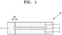
- FIG. 1 is a schematic cross-sectional view of an electrode structure 10 according to an embodiment.
- FIG. 2A is a schematic perspective view that shows an electrode structure 30 in a stack form, according to an embodiment.
- FIG. 2B is a schematic cross-sectional view that shows an inside of the electrode structure of FIG. 2A (a dotted circle).
- the electrode structure 10 includes a cathode layer 1, a solid electrolyte layer 2, and an anode layer 3 that are sequentially stacked, and an insulating layer 4 is located at two sides (e.g., two opposite sides or both sides) integrally surrounding the cathode layer 1, the solid electrolyte layer 2, and the anode layer 3.
- the solid electrolyte layer 2 has a margin w at two ends (e.g., two opposite sides or both ends) in a width direction.
- a width of the margin w may be about 0.5 mm or less.
- the margin w may be a distance that the solid electrolyte layer 2 extends past the cathode layer 1 and/or the anode layer 2 in the width direction, and the respective widths of the margin w at the two opposite sides may be the same or substantially the same as each other.
- the electrode structure 30 has a bi-cell structure in a stack form.
- the electrode structure 30 has cathode layers 26 and 26' including cathode active material layers 22 and 22' on upper and lower surfaces of a cathode current collector 21, respectively; solid electrolyte layers 23 and 23' on one surface of the cathode layers 26 and 26', respectively; anode active material layers 25 and 25' on one surface of the solid electrolyte layers 23 and 23', respectively; and anode layers 27 and 27' including anode active material layers 25 and 25' and anode current collectors 24 and 24', respectively.
- Insulating layers 28 and 28' are on each of two sides (e.g., two opposite sides or both sides) of the cathode layers 26 and 26', the solid electrolyte layers 23 and 23', and the anode layers 27 and 27', respectively.
- the electrode structure 30 may have a jelly-roll form or a stack form. Cracks may not occur in the electrode structure 30 when the electrode structure 30 is compressed in a thickness direction to about 20 % to about 30 % of a thickness of the electrode structure 30 (e.g., about 20% to about 30% of an initial thickness of the electrode structure 30).
- the insulating layer 28 or 28' may have a storage modulus (E') of greater than about 4.0 GPa.
- the electrode structure 10 or 30 including the insulating layers 28 and 28' having the storage modulus (E') is not deformed by pressing during preparation of a battery in a jelly-roll form or a stack form, and a short-circuit in the battery may be prevented (or a likelihood or degree of such a short-circuit may be reduced).
- the insulating layer 28 or 28' may have a loss tangent (tan ⁇ ) of less than about 0.5.
- a loss tangent (tan ⁇ ) is a ratio of a storage non-elastic modulus (E") to a storage elastic modulus (E'), which is E"/E'.
- a loss tangent (tan ⁇ ) is related to restoring force. Restoring force is a force that restores an electrode structure after being compressed by pressing during preparation of a battery, which reduces a possibility of short-circuit occurrence during charging and discharging of the battery.
- a loss tangent (tan ⁇ ) of the insulating layer 28 or 28' is low when the loss tangent (tan ⁇ ) of a solid electrolyte layer is in a range of about 0.05 to about 0.15. Therefore, the restoring force of the electrode structure 10 or 30 is exercised or relied upon during preparation of a battery, and thus, deformation by pressing does not occur, which results in prevention of a short-circuit (or a reduction in a likelihood or degree of such a short-circuit).
- a storage elastic modulus (E') and a storage non-elastic modulus (E") of the insulating layer 28 or 28' may be obtained by dynamic mechanical analysis (DMA).
- DMA dynamic mechanical analysis
- a storage elastic modulus (E') and a storage non-elastic modulus (E") may be derived by applying an external force in the form of a sine wave having a frequency of 1 Hz to a sample having a size of 10 mm x 5 mm and measuring the displacement and phase of the sample deformed according to the force.
- the insulating layer 28 or 28' may have a resistivity of about 1 ⁇ 10 6 ohm/cm or greater.
- the insulating layer 28 or 28' may be electrically insulated to suppress a short-circuit in the electrode structure 10 or 30(or to reduce a likelihood or degree of such a short circuit).
- the insulating layer 28 or 28' may be at least one layer.
- the insulating layer 28 or 28' may be a multilayer including two layers or three layers.
- the number of layers of the insulating layer 28 or 28' may be controlled or set to be within a range that satisfies the storage elastic modulus (E'), the storage non-elastic modulus (E"), and the loss tangent (tan ⁇ ).
- the insulating layer 28 or 28' may include a polymer or a composite of a polymer and an inorganic material.
- the polymer may include a fluorine-based polymer, a cellulose-based polymer, an epoxy-based resin, or a combination thereof.
- the fluorine-based polymer may include a homopolymer of vinylidene fluoride monomers or a copolymer of a fluorine-containing monomer of a vinylidene fluoride monomer and at least one selected from tetrafluoroethylene, hexafluoropropylene, chlorotrifluoroethylene, fluorovinyl, and perfluoroalkyl vinyl ether.
- the vinylidene monomer may include, for example, a vinylidene fluoride homopolymer, a vinylidene fluoride-hexafluoropropylene copolymer, or a vinylidene fluoride-chlorotrifluoroethylene copolymer.
- the fluorine-based polymer may be a copolymer of a monomer containing a polar functional group and a vinylidene fluoride monomer, or may further include a copolymer of a monomer containing a polar functional group, a vinylidene fluoride monomer, and any other fluorine-based monomer described above.
- the vinylidene fluoride polymer containing a polar functional group may include a polar functional group-containing monomer-vinylidene fluoride copolymer, a polar functional group-containing monomer-vinylidene fluoride-hexafluoropropylene copolymer, or a polar functional group-containing monomer-vinylidene fluoride-chlorotrifluoroethylene copolymer.
- the polar functional group may be at least one selected from a carboxylic acid group, a sulfonic acid group, a phosphoric acid group, a hydroxyl group, and salts thereof, but embodiments are not limited thereto, and any suitable polar functional group available in the art may be used.
- Introduction of the polar functional group into the fluorine-based polymer may be performed by polymerizing monomers including at least one selected from a carboxylic acid group, a sulfonic acid group, a phosphoric acid group, a hydroxyl group, and a salt thereof.
- monomers having a carboxylic acid group may include monocarboxylic acid and a derivative thereof, and dicarboxylic acid and a derivative thereof.
- monocarboxylic acid may include acrylic acid, methacrylic acid, and crotonic acid.
- Examples of the derivative of monocarboxylic acid may include 2-ethylacrylic acid, isocrotonic acid, ⁇ -acetoxyacrylic acid, ⁇ -trans-aryloxyacrylic acid, ⁇ -chloro- ⁇ -E-methoxy acrylic acid, and ⁇ -diaminoacrylic acid.
- Examples of the dicarboxylic acid may include maleic acid, fumaric acid, and itaconic acid.
- Examples of the derivative of dicarboxylic acid may include maleic acid, such as methyl maleic acid, dimethyl maleic acid, phenyl maleic acid, chloro maleic acid, dichloro maleic acid, and fluoromaleic acid; and maleic acid salt, such as methylallyl maleate, diphenyl maleate, nonyl hydrogen maleate, decyl hydrogen maleate, dodecyl hydrogen maleate, octadecyl hydrogen maleate, and fluoroalkyl maleate.
- maleic acid such as methyl maleic acid, dimethyl maleic acid, phenyl maleic acid, chloro maleic acid, dichloro maleic acid, and fluoromaleic acid
- maleic acid salt such as methylallyl maleate, diphenyl maleate, nonyl hydrogen maleate, decyl hydrogen maleate, dodecyl hydrogen maleate, octadecyl hydrogen maleate, and fluoroalkyl maleate.
- an acid anhydride that produces
- an acid anhydride of the dicarboxylic acid examples include an maleic anhydride, an acrylic anhydride, a methyl maleic anhydride, and a dimethyl maleic anhydride.
- a monoester and a diester of ⁇ , ⁇ -ethylenically unsaturated polyvalent carboxylic acid such as monoethyl maleate, diethyl maleate, monobutyl maleate, dibutyl maleate, monoethyl fumareate, diethyl fumareate, monobutyl fumareate, dibutyl fumareate, monocyclohexyl fumareate, dicyclohexyl fumareate, monoethyl itaconate, diethyl itaconate, monobutyl itaconate, and/or dibutyl itaconate, may be further used.
- Examples of a monomer having a sulfonic acid group may include vinylsulfonic acid, methyl vinylsulfonic acid, (meth)allylsulfonic acid, styrenesulfonic acid, (meth)acrylic acid-2-ethyl sulfonic acid, 2-acrylamid-2-methylpropanesulfonic acid, and 3-allyloxy-2-hydroxypropanesulfonic acid.
- Examples of a monomer having a phosphoric acid group may include phosphate 2-(meth)acryloyloxyethyl, phosphoric acid methyl-2-(meth)acryloyloxyethyl, and phosphoric acid ethyl-(meth)acryloyloxyethyl.
- Examples of the cellulose-based polymer may include at least one selected from cellulose, methyl cellulose, ethyl cellulose, butyl cellulose, hydroxypropyl cellulose, cellulose acetate, cellulose acetate propionate, and cellulose acetate butyrate.
- a type or kind of the cellulose-based polymer is not limited, but an example of the cellulose-based polymer may include a nanofiber type or kind.
- the cellulose-based polymer has excellent mechanical strength and optical transparency. Thus, a battery including the cellulose-based polymer as the insulating layer 28 or 28' may have excellent lifespan characteristics and stability.
- the epoxy-based resin may be at least one selected from a cresol novolac epoxy resin, a bisphenol A-type epoxy resin, a bisphenol A-type novolac epoxy resin, a phenol novolac epoxy resin, a tetrafunctional epoxy resin, a biphenyl-type epoxy resin, a triphenolmethane-type epoxy resin, an alkyl-modified triphenol methane epoxy resin, a naphthalene-type epoxy resin, a dicyclopentadiene-type epoxy resin, a dicyclopentadiene-modified phenol-type epoxy resin, a urethane-modified epoxy resin, and a combination thereof, but embodiments are not limited thereto.
- the epoxy-based resin has excellent mechanical properties and electric insulating properties.
- a volume ratio of the polymer in the composite of the polymer and the inorganic material may be about 50 vol% or greater based on 100 vol% of a total composition forming the composite.
- Physical properties such as a storage elastic modulus (E') and a storage non-elastic modulus (E") of the insulating layer 28 or 28' may be enhanced when a volume ratio of the polymer is within this range.
- strength and a storage elastic modulus (E') of the composite of the polymer and the inorganic material may increase but a storage non-elastic modulus (E") may also increase.
- a weight ratio of the polymer to the inorganic material in the composite of the polymer and the inorganic material may be in a range of about 1:1 to about 1:5.
- a weight ratio of the polymer and the inorganic material is within this range, physical properties such as a storage elastic modulus (E') and a storage non-elastic modulus (E") of the insulating layer 28 or 28' may be enhanced.
- the inorganic material may include a metal oxide, a metal hydroxide, or a combination thereof.
- Examples of the inorganic material may include Al 2 O 3 and Al(OH) 3 , but embodiments are not limited thereto, and any suitable inorganic material that may be used in an all-solid secondary battery in the art may be used.
- the cathode layer 26 or 26' includes a cathode current collector 21 and a cathode active material layer 22 or 22' on at least one surface of the cathode current collector 21.
- the cathode active material layer 22 or 22' may include, for example, a cathode active material and a solid electrolyte.
- the solid electrolyte in the cathode layer 26 or 26' may be similar to or different from a solid electrolyte in the solid electrolyte layer 23 or 23'.
- the solid electrolyte may include a sulfide-based solid electrolyte. Additional details about the solid electrolyte may be the same as described in relation to the solid electrolyte layer 23 or 23'.
- the cathode active material may be a cathode active material capable of reversibly absorbing and desorbing lithium ions (e.g., capable of reversibly intercalating and deintercalating lithium ions).
- the cathode active material include, for example, a lithium transition metal oxide such as lithium cobalt oxide (LCO), lithium nickel oxide, lithium nickel cobalt oxide, lithium nickel cobalt aluminum oxide (NCA), lithium nickel cobalt manganese oxide (NCM), lithium manganate, and lithium iron phosphate; nickel sulfide, copper sulfide, lithium sulfide; iron oxide, and vanadium oxide, but embodiments are not limited thereto, and any suitable cathode active material may be used.
- the cathode active material may be used alone or in a mixture of at least two selected from these examples.
- the lithium transition metal oxide may be, for example, a compound represented by one of the following formulae:
- the cathode active material may include, for example, a lithium salt of a transition metal oxide that has a layered rock-salt type structure among the examples of the lithium transition metal oxide.
- layered rock-salt type structure refers to a structure in which an oxygen atom layer and a metal atom layer are alternately and regularly arranged in a ⁇ 111> direction in a cubic rock-salt type structure, where each of the atom layers forms a two-dimensional flat plane.
- cubic rock-salt type structure refers to a sodium chloride (NaCl) type structure, which is one of the crystalline structures, for example, to a structure in which face-centered cubic (fcc) lattices respectively formed of anions and cations are shifted by only a half of the ridge of each unit lattice.
- NaCl sodium chloride
- fcc face-centered cubic
- NCA LiNi x Co y Al z O 2
- NCM LiNi x Co y Mn z O 2
- the cathode active material may be covered by a coating layer as described above.
- the coating layer is any suitable material that may be used as a coating layer of a cathode active material of an all-solid secondary battery in the art.
- the coating layer may be, for example, Li 2 O-ZrO 2 (LZO).
- the cathode active material includes nickel (Ni) as a ternary lithium transition metal oxide such as NCA or NCM
- Ni nickel
- NCM ternary lithium transition metal oxide
- a capacity density of the all-solid secondary battery increases, and thus, metal elution from the cathode active material in a charged state may be reduced.
- the all-solid secondary battery according to an embodiment may have improved cycle characteristics in a charged state.
- a shape of the cathode active material may be, for example, particle shapes such as a true spherical shape, an elliptical shape, or a spherical shape (e.g., a generally spherical shape).
- a particle diameter of the cathode active material is not particularly limited but may be in any suitable range applicable to a cathode active material of an all-solid secondary battery of the related art.
- An amount of the cathode active material of the cathode layer 26 or 26' is not particularly limited and may be in any suitable range applicable to a cathode layer of an all-solid secondary battery of the related art.
- a D50 average particle diameter of the solid electrolyte in the cathode active material layer 22 or 22' may be less than that of the solid electrolyte in the solid electrolyte layer 23 or 23'.
- a D50 average particle diameter of the solid electrolyte in the cathode active material layer 22 or 22' may be about 90 % or less, about 80 % or less, about 70 % or less, about 60 % or less, about 50 % or less, about 40 % or less, about 30 % or less, or about 20 % or less of a D50 average particle diameter of the solid electrolyte in the solid electrolyte layer 23 or 23'.
- a D50 average particle diameter may be, for example, a median particle diameter (D50).
- the median particle diameter (D50) may be, for example, a size of the particle corresponding to 50% of the cumulative volume calculated from the size of a particle having a small particle size in the particle size distribution, as measured by a laser diffraction method.
- the cathode active material layer 22 or 22' may include a binder.
- the binder may include styrene butadiene rubber (SBR), polytetrafluoroethylene, polyvinylidene fluoride, and polyethylene, but embodiments are not limited thereto, and any suitable material available as a binder in the art may be used.
- SBR styrene butadiene rubber
- polytetrafluoroethylene polyvinylidene fluoride
- polyethylene but embodiments are not limited thereto, and any suitable material available as a binder in the art may be used.
- the cathode active material layer 22 or 22' may include a conducting agent.
- the conducting agent may include graphite, carbon black, acetylene black, ketjen black, carbon fiber, and metal powder, but embodiments are not limited thereto, and any suitable material available as a conducting agent in the art may be used.
- the cathode active material layer 22 or 22' may further include, for example, additives such as a filler, a coating agent, a dispersant, and an ion conducting agent in addition to the cathode active material, solid electrolyte, binder, and conducting agent.
- additives such as a filler, a coating agent, a dispersant, and an ion conducting agent in addition to the cathode active material, solid electrolyte, binder, and conducting agent.
- the filler, coating agent, dispersant, and ion conducting agent that may be included in the cathode active material layer 22 or 22' may be any suitable material that is generally used in an electrode of an all-solid secondary battery in the art.
- a mixture density of the cathode active material layer 22 or 22' may be 3.0 g/cc or higher.
- the cathode current collector 21 may be a plate or a foil formed of, for example, indium (In), copper (Cu), magnesium (Mg), stainless steel, titanium (Ti), iron (Fe), cobalt (Co), nickel (Ni), zinc (Zn), aluminum (Al), germanium (Ge), lithium (Li), and/or an alloy thereof.
- the cathode current collector 21 may be omitted.
- a thickness of the cathode current collector 21 may be, for example, in a range of about 1 ⁇ m to about 100 ⁇ m, about 1 ⁇ m to about 50 ⁇ m, about 5 ⁇ m to about 25 ⁇ m, or about 10 ⁇ m to about 20 ⁇ m.
- the solid electrolyte layer 2, 23, or 23' may include a solid electrolyte between the cathode layer 1, 26, or 26' and the anode layer 3, 27, or 27'.
- the solid electrolyte may be, for example, a sulfide-based solid electrolyte.
- the sulfide-based solid electrolyte may be, for example, at least one selected from Li 2 S-P 2 S 5 , Li 2 S-P 2 S 5 -LiX (where X is a halogen), Li 2 S-P 2 S 5 -Li 2 O, Li 2 S-P 2 S 5 -Li 2 O-LiI, Li 2 S-SiS 2 , Li 2 S-SiS 2 -LiI, Li 2 S-SiS 2 -LiBr, Li 2 S-SiS 2 -LiCl, Li 2 S-SiS 2 -B 2 S 3 -LiI, Li 2 S-SiS 2 -P 2 S 5 -LiI, Li 2 S-B 2 S 3 , Li 2 S-P 2 S 5 -Z m S n (where m and n are each independently a positive
- the sulfide-based solid electrolyte may be prepared by melting and quenching starting materials (e.g., Li 2 S and/or P 2 S 5 ), or mechanically milling the starting materials. Subsequently, the resultant may be heat-treated.
- the solid electrolyte may be amorphous and/or crystalline and may be a mixed form thereof. Also, the solid electrolyte may include at least sulfur (S), phosphorus (P), and lithium (Li), as component elements among the sulfide-based solid electrolyte materials.
- the solid electrolyte may be a material including Li 2 S-P 2 S 5 .
- a mixing molar ratio of Li 2 S and P 2 S 5 may be, for example, selected in a range of about 50:50 to about 90:10.
- the sulfide-based solid electrolyte may include, for example, an argyrodite-type solid electrolyte represented by Formula 1.
- Formula 1 Li + 12-n-x A n+ X 2- 6-x Y - x
- A is P, As, Ge, Ga, Sb, Si, Sn, Al, In, Ti, V, Nb, or Ta
- X is S, Se, or Te
- Y is CI, Br, I, F, CN, OCN, SCN, or N 3 , 1 ⁇ x ⁇ 5, and 0 ⁇ n ⁇ 2.
- the sulfide-based solid electrolyte may be, for example, an argyrodite-type compound including at least one selected from Li 7-x PS 6-x Cl x (where 0 ⁇ x ⁇ 2), Li 7-x PS 6-x Br x (where 0 ⁇ x ⁇ 2), and Li 7-x PS 6-x I x (where 0 ⁇ x ⁇ 2).
- the sulfide-based solid electrolyte may be, for example, an argyrodite-type compound including at least one selected from Li 6 PS 5 Cl, Li 6 PS 5 Br, and Li 6 PS 5 I.
- a density of the argyrodite-type solid electrolyte may be in a range of about 1.5 g/cc to about 2.0 g/cc.
- the argyrodite-type solid electrolyte has a density of about 1.5 g/cc or higher, internal resistance of an all-solid secondary battery may decrease, and thus penetration of the solid electrolyte layer by Li may be effectively suppressed or reduced.
- the solid electrolyte layer 2, 23, or 23' may include, for example, a binder.
- the binder included in the solid electrolyte layer 2, 23, or 23' may include styrene butadiene rubber (SBR), polytetrafluoroethylene, polyvinylidene fluoride, and polyethylene, but embodiments are not limited thereto, and any suitable material available as a binder in the art may be used.
- SBR styrene butadiene rubber
- the binder of the solid electrolyte layer 2, 23, or 23' may be the same as or different from binders of the cathode active material layer 22 or 22' and the anode active material layer 25 or 25'.
- the binder may be omitted.
- An amount of the binder in the solid electrolyte layer 2, 23, or 23' may be in a range of about 0 wt% to about 10 wt%, about 0 wt% to about 5 wt%, about 0 wt% to about 3 wt%, about 0 wt% to about 1 wt%, about 0 wt% to about 0.5 wt%, or about 0 wt% to about 0.1 wt%, based on the total weight of the solid electrolyte layer 2, 23, or 23'.
- a peel strength of the solid electrolyte layer 2, 23, or 23' to the cathode layer 26 or 26' or to the anode layer 27 or 27' may be about 0.2 gf/mm or greater.
- the anode layer 27 or 27' may include an anode current collector 24 or 24', respectively, and an anode active material layer 25 or 25' on at least one surface of the anode current collector 24 or 24', respectively.
- the anode active material layer 25 or 25' may include, for example, an anode active material and a binder.
- the anode active material in the anode active material layer 25 or 25' may have, for example, a particle shape.
- An average particle diameter of the anode active material having a particle shape may be, for example, about 4 ⁇ m or less, about 3 ⁇ m or less, about 2 ⁇ m or less, about 1 ⁇ m or less, or about 900 nm or less.
- the average particle diameter of the anode active material having a particle shape may be, for example, about 10 nm to about 4 ⁇ m, about 10 nm to about 3 ⁇ m, about 10 nm to about 2 ⁇ m, about 10 nm to about 1 ⁇ m, or about 10 nm to about 900 nm.
- the average particle diameter of the anode active material may be, for example, a median diameter (D50) as measured utilizing a laser particle size distribution meter.
- the anode active material included in the anode active material layers 25 or 25' includes, for example, at least one selected from a carbon-based anode active material and a metal and/or metalloid anode active material.
- the carbon-based anode active material may include at least one selected from amorphous carbon and crystalline carbon.
- the carbon-based anode active material may be, for example, amorphous carbon.
- Examples of the amorphous carbon may include carbon black (CB), acetylene black (AB), furnace black (FB), ketjen black (KB), and graphene, but embodiments are not limited thereto, and any suitable amorphous carbon may be used as long as it is classified as amorphous carbon in the related art.
- Amorphous carbon is carbon having no crystallinity or having very low crystallinity, and is distinguished from crystalline carbon or graphite-based carbon.
- the metal or metalloid anode active material includes at least one selected from gold (Au), platinum (Pt), palladium (Pd), silicon (Si), silver (Ag), aluminum (Al), bismuth (Bi), tin (Sn), and zinc (Zn), but embodiments are not limited thereto, and any suitable metal or metalloid anode active material may be used as long as it is utilized to form an alloy or compound with lithium in the related art. For example, because nickel (Ni) does not form an alloy with lithium, it is not utilized as a metal anode active material.
- the anode active material layer 25 or 25' includes one selected from among these anode active materials, or includes a mixture of a plurality of different anode active materials.
- the anode active material layer 22 includes only amorphous carbon, or includes at least one selected from gold (Au), platinum (Pt), palladium (Pd), silicon (Si), silver (Ag), aluminum (Al), bismuth (Bi), tin (Sn), and zinc (Zn).
- the anode active material layer 25 or 25' includes a mixture of amorphous carbon and at least one selected from gold (Au), platinum (Pt), palladium (Pd), silicon (Si), silver (Ag), aluminum (Al), bismuth (Bi), tin (Sn), and zinc (Zn).
- a mixing ratio of the mixture of amorphous carbon and gold may be, for example, about 10:1 to about 1:2, about 5:1 to about 1:1, or about 4:1 to about 2:1 by weight, but embodiments are not limited thereto, and the mixing ratio is selected according to required characteristics of an all-solid secondary battery. When the anode active material has the composition, the cycle characteristics of the all-solid secondary battery may further improve.
- the anode active material included in the anode active material layer 25 or 25' may include, for example, a mixture of first particles formed of amorphous carbon and second particles formed of metal or metalloid.
- the metal or metalloid may include gold (Au), platinum (Pt), palladium (Pd), silicon (Si), silver (Ag), aluminum (Al), bismuth (Bi), tin (Sn), and zinc (Zn).
- the metalloid may be a semiconductor.
- An amount of the second particles may be about 8 wt% to about 60 wt%, about 10 wt% to about 50 wt%, about 15 wt% to about 40 wt%, or about 20 wt% to about 30 wt% based on the total weight of the mixture. When the amount of the second particles is within these ranges, cycle characteristics of the all-solid secondary battery may further improve.
- binder included in the anode active material layer 25 or 25' may include styrene-butadiene rubber (SBR), polytetrafluoroethylene, polyvinylidene fluoride, polyethylene, vinylidene fluoride/hexafluoropropylene copolymer, polyacrylonitrile, and polymethylmethacrylate, but embodiments are not limited thereto, and any suitable binder may be used as long as it is utilized as a binder in the related art.
- the binder may consist of a single binder or multiple different binders.
- the anode active material layer 25 or 25' may be stabilized on the anode current collector 24 or 24'. Also, in the charging/discharging process, cracks of the anode active material layer 25 or 25' may be suppressed or reduced regardless of the volume change and/or the relative position change of the anode active material layer 25 or 25'. For example, when the anode active material layer 25 or 25' does not include a binder, it is possible for the anode active material layers 25 or 25' to be easily separated from the anode current collector 24 or 24'.
- the anode current collector 24 or 24' may be exposed to come into contact with the solid electrolyte layer 23 or 23', thereby increasing the possibility of an occurrence of a short circuit.
- the anode active material layer 25 or 25' is prepared by applying a slurry in which materials constituting the anode active material layer 25 or 25' are dispersed onto the anode current collector 24 or 24' and then drying the slurry. It is possible to stably disperse the anode active material in the slurry by including the binder in the anode active material layer 25 or 25'.
- the slurry when the slurry is applied onto the anode current collector 24 or 24' by a screen printing method, it is possible to suppress or reduce the clogging of a screen (for example, clogging of a screen by aggregates of the anode active material).
- the anode active material layer 25 or 25' may further include additives such as a filler, a coating agent, a dispersant, and an ion conducting agent used in an all-solid secondary battery of the related art.
- a thickness of the anode active material layer 25 or 25' may be, for example, about 50 % or less, about 40 % or less, about 30 % or less, about 20 % or less, about 10 % or less, or about 5 % or less of a thickness of the cathode active material layer 22 or 22'.
- a thickness of the anode active material layer 25 or 25' may be, for example, in a range of about 1 ⁇ m to about 20 ⁇ m, about 2 ⁇ m to about 10 ⁇ m, or about 3 ⁇ m to about 7 ⁇ m.
- the anode active material layer 25 or 25' When the thickness of the anode active material layer 25 or 25' is too thin, the anode active material layer 25 or 25' may be disintegrated or damaged by lithium dendrites which are generated between the anode active material layer 25 or 25' and the anode current collector 24 or 24', which may deteriorate cycle characteristics of the all-solid secondary battery.
- the anode active material layer 25 or 25' When the anode active material layer 25 or 25' is too thick, the all-solid secondary battery may have a reduced energy density and an increased internal resistance, and thus, the all-solid secondary battery may have poor cycle characteristics.
- the anode active material 25 or 25' may have a reduced charge capacity.
- a charge capacity of the anode active material layer 25 or 25' may be about 50 % or less, about 40 % or less, about 30 % or less, about 20 % or less, about 10 % or less, about 5 % or less, or about 2 % or less of a charge capacity of the cathode active material layer 22 or 22'.
- the charge capacity of the anode active material layer 25 or 25' may be, for example, in a range of about 0.1 % to about 50 %, about 0.1 % to about 40 %, about 0.1 % to about 30 %, about 0.1 % to about 20 %, about 0.1 % to about 10 %, about 0.1 % to about 5 %, or about 0.1 % to about 2 % of a charge capacity of the cathode active material layer 22 or 22'.
- the all-solid secondary battery may have poor lifespan characteristics.
- the charge capacity of the anode active material layer 25 or 25' increases excessively, the all-solid secondary battery may have a reduced energy density and an increased internal resistance, and thus, the all-solid secondary battery may have poor lifespan characteristics.
- the charge capacity of the cathode active material layer 22 or 22' may be obtained by multiplying a charge capacity density (mAh/g) of a cathode active material by a weight of the cathode active material in the cathode active material layer 22 or 22'.
- a charge capacity density of each of the cathode active material layers may be multiplied by a respective weight thereof, and then the sum of the multiplication products may be calculated as the charge capacity of the cathode active material layer 22 or 22'.
- the charge capacity of the anode active material layer 25 or 25' may be calculated in the same manner.
- the charge capacity of the anode active material layer 25 or 25' may be obtained by multiplying a charge capacity density (mAh/g) of an anode active material by a weight of the anode active material in the anode active material layer 25 or 25'.
- a charge capacity density of each of the anode active material layers may be multiplied by a respective weight thereof, and then the sum of the multiplication products may be calculated as the charge capacity of the anode active material layer 25 or 25'.
- the charge capacity densities of the cathode active material and the anode active material are estimated capacities obtained for an all-solid half-cell including lithium metal as a counter electrode.
- the charge capacities of the cathode active material layer 22 or 22' and the anode active material layer 25 or 25' are directly calculated by charge capacity measurement using an all-solid half-cell.
- the measured charge capacity of each of the cathode active material and the anode active material may be divided by a weight of the corresponding active material, thereby obtaining a charge capacity density.
- the charge capacities of the cathode active material layer 22 or 22' and the anode active material layer 25 or 25' may be initial charge capacities measured after the 1st charging cycle.
- the anode current collector 24 or 24' may be composed of a material that does not react with lithium to form an alloy or a compound.
- the material of the anode current collector 24 or 24' may include copper (Cu), stainless steel, titanium (Ti), iron (Fe), cobalt (Co), and nickel (Ni), but embodiments are not limited thereto, and any suitable material available as an electrode current collector in the art may be used.
- the anode current collector 24 or 24' may be formed of one of the examples of the metal or an alloy or a coating material of at least two metals selected from the examples.
- the anode current collector 24 or 24' may be, for example, in the form of a plate or a foil.
- An all-solid secondary battery may include the electrode structure 10 or 30.
- FIG. 3 is a schematic view of an all-solid secondary battery 40 according to an embodiment.
- the electrode structure 40 has cathode layers 36 and 36' on cathode active material layers 32 and 32' on upper and lower surfaces of a cathode current collector 31, respectively; solid electrolyte layers 33 and 33' on one surface of the cathode layers 36 and 36', respectively; and anode layers 37 and 37' including anode active material layers 34 and 34' and anode current collectors 35 and 35' on one surface of the solid electrolyte layers 33 and 33', respectively.
- Insulating layers 38 and 38' are located at each of two sides (e.g., two opposite sides or both sides) of the cathode layers 36 and 36', the solid electrolyte layers 33 and 33', and the anode layers 37 and 37', respectively.
- Supporting members 39 and 39' are on one surface of the anode current collectors 35 and 35', respectively.
- the all-solid secondary battery 40 is prepared by being subject to a warm isostatic press (WIP) to the supporting members 39 and 39' on upper and lower surfaces and forming each of a cathode terminal and an anode terminal.
- WIP warm isostatic press
- the all-solid secondary battery 40 may include the insulating layer 38 or 38' on two sides (e.g., two opposite sides or both sides) of the cathode layer 36 or 36', the solid electrolyte layer 33 or 33', and the anode layer 37 or 37' to suppress a short-circuit (or reduce a likelihood or degree of such a short-circuit), which minimizes or reduces initial capacity reduction, and thus, may improve lifespan characteristics.
- Example 1 All-solid secondary battery including PVdF + Al 2 O 3 insulating layer
- a stainless steel (SUS) foil having a thickness of 10 ⁇ m was prepared as an anode current collector.
- carbon black (CB) having a primary particle diameter (D50) of about 35 nm and silver (Ag) particles having an average particle diameter of about 60 nm were prepared as an anode active material.
- 4 g of a mixture powder prepared by mixing together the carbon black (CB) and silver (Ag) particles at a weight ratio of about 3:1 was put in a container, and 4 g of a N-methyl-2-pyrrolidone (NMP) solution including about 7 weight% (wt%) of a PVDF binder (#9300 available from Kureha Co.) was added to the container to prepare a mixture solution.
- NMP N-methyl-2-pyrrolidone
- anode layer A thickness of an anode active material layer of a silver-carbon (Ag-C) nanocomposite in the anode layer was about 7 ⁇ m.
- a silver (Ag) volume ratio in the Ag-C nanocomposite was about 8 vol%, and an amount of Ag used in preparation of a battery was about 12 mg/Ah.
- Li 2 O-ZrO 2 (LZO)-coated LiNi 0.8 Co 0.15 Mn 0.05 O 2 (NCM) was prepared as a cathode active material.
- the LZO-coated cathode active material was prepared according to the method disclosed in Korean Patent No. 10-2016-0064942 , the entire content of which is incorporated herein by reference.
- a Li 6 PS 5 Cl solid electrolyte (D50 0.5 ⁇ m, crystalline), which is an argyrodite-type crystal, was prepared as a solid electrolyte.
- a polytetrafluoroethylene (PTFE) binder (Teflon binder, available from DuPont) was prepared as a binder.
- PTFE polytetrafluoroethylene
- the thus prepared slurry was applied on a polyethylene terephthalate film having a thickness of 75 ⁇ m using a doctor blade and dried on a hot plate at a temperature of 50 °C for several minutes to obtain a stack.
- the stack was vacuum-dried at a temperature of about 40 °C for about 8 hours.
- a sold electrolyte layer was prepared.
- a thickness of the solid electrolyte layer was about 40 ⁇ m, and the solid electrolyte layer was pressed in a battery so that the thickness was about 30 ⁇ m.
- a PVdF powder (#9300, available from Kureha Corporation) and an Al 2 O 3 powder (50 nm, available from Sigma Aldrich) at a weight ratio of 1:3 were added and mixed together to prepare a mixture powder, 40 g of the mixture powder was put into a container, and an acetone solvent was added thereto to prepare a mixture solution. Subsequently, the mixture solution was stirred while gradually adding an acetone solvent to the mixture solution to prepare a slurry for an insulating layer.
- a solid electrolyte layer 33 was on an anode layer 37 such that an anode active material layer 34 is in contact with the solid electrolyte layer 33, and a cathode layer 36 was on the solid electrolyte layer 33 to prepare a stack.
- a margin of a width of the solid electrolyte layer 33 was about 2 %.
- the slurry for an insulating layer was integrally applied onto both surfaces of the stack including the anode layer 37, the cathode layer 36, and the solid electrolyte layer 33 using a doctor blade and was dried in air to prepare an electrode structure having an insulating layer 38.
- the insulating layer 38 had a storage elastic modulus (E') of 6.471 GPa and a loss tangent (tan ⁇ ) of 0.045.
- E' storage elastic modulus
- tan ⁇ loss tangent
- the electrode structure having the insulating layer 38 on its both surfaces was placed in a laminate bag and vacuum sealed. Then, the vacuum sealed electrode structure was subjected to warm isostatic pressing (WIP) at a pressure of 500 MPa.
- WIP warm isostatic pressing
- the electrode structure was taken from the laminate bag, and the Al and Ni terminals were each respectively welded onto the cathode and the anode using an ultrasonic welder. Subsequently, the electrode structure having the Al and Ni terminals projecting therefrom was placed in a laminate bag and vacuum sealed to prepare an all-solid secondary battery 40.
- Example 2 All-solid secondary battery including cellulose+glass fiber+Al(OH) 3 insulating layer
- nanocellulose clay for art, available from Pinocchio Corporation
- Al(OH) 3 powder 5 ⁇ m, available from Sigma Aldrich
- an all-solid secondary battery 40 was prepared in substantially the same manner as in Example 1, except that the slurry for an insulating layer was dried at 100 °C for 12 hours to form an insulating layer 38 in a shape of a sheet, and the insulating layer 38 was punched in a shape of a square frame " ⁇ " to have an inner diameter of the same size as that of the solid electrolyte layer 33 of the stack including the anode layer 37, the cathode layer 36, and the solid electrolyte layer 33 such that the insulating layer 38 surrounds four sides of the stack without separate adhesion.
- the insulating layer 38 has a storage elastic modulus (E') of 19.87 GPa and a loss tangent (tan ⁇ ) was 0.024.
- Example 3 All-solid secondary battery including insulating layer having 3-layer structure of cellulose+epoxy resin+cellulose
- An all-solid secondary battery 40 was prepared in substantially the same manner as in Example 1, except that 2 g of an epoxy adhesive (EP935, available from Okong Corporation) was applied between two sheets of cellulose paper having a thickness of 60 ⁇ m instead of the slurry for an insulating layer to prepare an insulating layer structure of a 3-layer structure, in which cellulose, an epoxy resin, and cellulose were sequentially stacked, and that the insulating stack was fixed on both sides surfaces of the stack including the anode layer 37, the cathode layer 36, and the solid electrolyte layer 33 using the epoxy adhesive.
- the insulating layer 38 has a storage elastic modulus (E') of 39.63 GPa and a loss tangent (tan ⁇ ) was 0.034.
- An all-solid secondary battery 40 was prepared in substantially the same manner as in Example 1, except that a polypropylene zirconia film (MKP1848C, a capacitor material (semi-finished product), available from Vishay) having a thickness of about 230 ⁇ m was prepared instead of the slurry for an insulating layer, and the film was punched in a shape of a square frame, " ⁇ ", to have an inner diameter of the same size as that of the solid electrolyte layer 33 of the stack including the anode layer 37, the cathode layer 36, and the solid electrolyte layer 33 such that the film surrounds four sides of the stack without separate adhesion.
- the insulating layer 38 had a storage elastic modulus (E') of 1.491 GPa and a loss tangent (tan ⁇ ) of 0.098.
- An all-solid secondary battery 40 was prepared in substantially the same manner as in Example 1, except that a transparent polymethylmethacrylate (PMMA) film (available from Sumitomo) having a thickness of about 350 ⁇ m was prepared instead of the slurry for an insulating layer, and the film was punched in a shape of a square frame, " ⁇ ", to have an inner diameter of the same size as that of the solid electrolyte layer 33 of the stack including the anode layer 37, the cathode layer 36, and the solid electrolyte layer 33 such that the film surrounds four sides of the stack without separate adhesion.
- the insulating layer 38 had a storage elastic modulus (E') of 2.520 GPa and a loss tangent (tan ⁇ ) of 0.157.
- An all-solid secondary battery 40 was prepared insubstantially the same manner as in Example 1, except that a polytetrafluoroethylene (PTFE) film (Hypersheet, available from Goretech) having a thickness of about 300 ⁇ m was prepared instead of the slurry for an insulating layer, and the film was punched in a shape of a square frame, " ⁇ ", to have an inner diameter of the same size as that of the solid electrolyte layer 33 of the stack including the anode layer 37, the cathode layer 36, and the solid electrolyte layer 33 such that the film surrounds four sides of the stack without separate adhesion.
- the insulating layer 38 had a storage elastic modulus (E') of 0.200 GPa and a loss tangent (tan ⁇ ) of 0.198.
- Charging and discharging characteristics of the all-solid secondary batteries prepared in Examples 1 to 3 and Comparative Examples 1 to 3 were evaluated by the following charge/discharge test.
- the charge/discharge test was performed with the all-solid secondary batteries each placed in a constant-temperature chamber of 45 °C.
- the battery was charged with a constant current of about 0.1 C until a battery voltage was about 4.25 V, and once the battery voltage reached 4.25 V, the battery was charged with a constant voltage until a charge current was about 0.05 C. Next, the battery was discharged with a constant current of about 0.1 C until a battery voltage was about 2.5 V.
- the all-solid secondary batteries prepared in Examples 1 to 3 had initial capacities that were the same as or improved from those of the all-solid secondary batteries prepared in Comparative Examples 1 to 3, and capacity retention rates of the all-solid secondary batteries prepared in Examples 1 to 3 were also improved.
- the all-solid secondary batteries prepared in Examples 1 to 3 include an insulating layer having a storage elastic modulus of 6.471 GPa or greater and a loss tangent of less than 0.045 at both sides of an electrode structure, which thus has a restoring force during charging and discharging of the battery while preventing or reducing occurrence of initial short-circuit, and thus, the all-solid secondary batteries prepared in Examples 1 to 3 had excellent initial capacity and capacity retention rate.
- an electrode structure includes a cathode layer, an anode layer, and a solid electrolyte layer between the cathode layer and the anode layer, wherein the solid electrolyte layer has no margin or a margin of about 2 % or less of a width of the solid electrolyte layer at both ends in a width direction, and an insulating layer having a storage elastic modulus (E') of greater than 4.0 GPa is at both sides integrally surrounds the cathode layer, the anode layer, and the solid electrolyte layer.
- E' storage elastic modulus
- the electrode structure may suppress a short-circuit (or reduce a likelihood or degree of such a short-circuit) by having the insulating layer even when the margin of the width of the solid electrolyte layer is very little or none, which reduces initial capacity, and thus, may provide an all-solid secondary battery having improved lifespan characteristics.
Landscapes
- Chemical & Material Sciences (AREA)
- General Chemical & Material Sciences (AREA)
- Chemical Kinetics & Catalysis (AREA)
- Electrochemistry (AREA)
- Engineering & Computer Science (AREA)
- Manufacturing & Machinery (AREA)
- Inorganic Chemistry (AREA)
- General Physics & Mathematics (AREA)
- Condensed Matter Physics & Semiconductors (AREA)
- Physics & Mathematics (AREA)
- Materials Engineering (AREA)
- Secondary Cells (AREA)
- Connection Of Batteries Or Terminals (AREA)
- Battery Electrode And Active Subsutance (AREA)
Abstract
Description
- One or more embodiments of the present disclosure relate to an electrode structure and an all-solid secondary battery including the electrode structure.
- In recent years, batteries having improved energy density and safety have been actively developed in accordance with industrial demand. For example, lithium-ion batteries have been put to practical use in the automotive industry as well as in information-related equipment and communication equipment. In the automotive industry, safety is particularly important to protect life. Lithium-ion batteries which are currently commercialized use an electrolytic solution including a flammable organic solvent, and thus there is a possibility of overheating and fire when a short-circuit occurs. As a result, an all-solid secondary battery using a solid electrolyte instead of an electrolytic solution has been proposed.
- Because an all-solid secondary battery does not use a flammable organic solvent, the possibility of fire or an explosion may be greatly reduced even when a short-circuit occurs. Therefore, such an all-solid secondary battery may greatly enhance safety as compared with a lithium-ion battery using an electrolytic solution.
- The present invention refers to an electrode structure for an all-solid secondary battery including an electrode structure as defined in
claim 1. Another aspect of the present invention refers to an all-solid secondary battery including the before-mentioned electrode structure. - Additional aspects of embodiments are defined in the depended claims or will be set forth in the description which follows.
- The above and other aspects-and features of certain embodiments of the disclosure will be more apparent from the following description taken in conjunction with the accompanying drawings, in which:
-
FIG. 1 is a schematic cross-sectional view of an electrode structure according to an embodiment. -
FIG. 2A is a schematic perspective view that shows an electrode structure in a stack form, according to an embodiment. -
FIG. 2B is a schematic cross-sectional view that shows an inside of the electrode structure ofFIG. 2A (a dotted circle). -
FIG. 3 is a schematic cross-sectional view of an all-solid secondary battery according to an embodiment; and -
FIG. 4 is a graph that shows lifespan characteristics of all-solid secondary batteries prepared in Examples 1 to 3 and Comparative Examples 1 and 2. - Reference will now be made in more detail to embodiments, examples of which are illustrated in the accompanying drawings, wherein like reference numerals refer to like elements throughout. In this regard, the present embodiments may have different forms and should not be construed as being limited to the descriptions set forth herein. Accordingly, the embodiments are merely described below, by referring to the figures, to explain aspects of embodiments of the present description. As used herein, the term "and/or" includes any and all combinations of one or more of the associated listed items. Expressions such as "at least one of," when preceding a list of elements, modify the entire list of elements and do not modify the individual elements of the list.
- Hereinafter, an electrode structure according to an embodiment and an all-solid secondary battery including the electrode structure will be described in more detail with reference to the accompanying drawings. These embodiments are provided for illustrative purposes only and are not intended to limit the scope of the present disclosure.
- Expressions such as "at least one of," when preceding a list of elements, modify the entire list of elements and do not modify the individual elements of the list. Unless otherwise stated herein, the term "combinations" is inclusive of mixtures, alloys, and reaction products.
- It will be understood that unless otherwise stated herein, the terms "comprises" and/or "comprising," or "includes" and/or "including" do not preclude other elements, but further include other elements.
- The terms "first," "second," and the like, do not denote any order, quantity, or importance, but rather are used to distinguish one element from another. The terms "a" and "an" and "the" do not denote a limitation of quantity, and are to be construed to cover both the singular and the plural, unless otherwise indicated herein or clearly contradicted by context.
- Reference throughout the specification to "some embodiments," "an embodiment," and so forth, means that a particular element described in connection with the embodiment is included in at least one embodiment described herein, and may or may not be present in other embodiments. In addition, it is to be understood that the described elements may be combined in any suitable manner in the various embodiments.
- All-solid secondary batteries in the art have good stability but have a solid electrolyte, which reduces flexibility and processability of all-solid secondary batteries as compared to those of lithium-ion batteries. In this regard, an electrode structure including a cathode plate, an anode plate, and an electrolyte layer may not secure suitable or sufficient margins of width between the electrode plates and the electrolyte layer. Also, burrs or cracks may occur at the edges of the outermost parts of the electrode plates and the electrolyte layer. In this case, a short-circuit may occur in the all-solid secondary battery, which may degrade capacity and lifespan characteristics of the all-solid secondary battery. The present inventors have reduced degradation of capacity and lifespan characteristics of embodiments of an all-solid secondary battery by providing a-layer at sides of an electrode structure. Hereinafter, an electrode structure and an all-solid secondary battery according to one or more embodiments will be described in more detail.
- An electrode structure, which is part of an all-solid secondary battery, includes a cathode layer, an anode layer, and a solid electrolyte layer-between the cathode layer and the anode layer. The cathode layer includes a cathode current collector and a cathode active material layer on at least one surface of the cathode current collector, the anode layer includes an anode current collector and an anode active material layer on at least one surface of the anode current collector. A base area of the solid electrolyte layer is larger than a base area of the anode layer and the cathode layer. The anode layer and the cathode layer are centrally positioned on the solid electrolyte layer in such a way that there is an extension of width on at least two sides of the solid electrolyte layer. In other words, the width of the solid electrolyte layer is larger than that of the electrode layers and when the electrode layers are placed on the solid electrolyte layer, there will be a kid of overlapping margin on at least two sides of the solid electrolyte layer. Said extension or margin may be provided on two opposite sides, three sides or even all sides of the solid electrolyte layer. The extension on each side of the solid electrolyte layer may have a width W between 0.5 to 2 % of the total width of the solid electrolyte layer. The solid electrolyte layer may have a margin of 2 % or less of a width of the solid electrolyte layer at two ends (e.g., two opposite ends or both ends) in a width direction.
- An electrically insulating layer covers a side surface of the electrode structure in such a way that at least a space extending laterally next to the anode layer and the cathode layer and having the same width W as the extension of the solid electrolyte layer is filled by the insulating layer. In other words, the insulating layer extends from at least the upper surface of the solid electrolyte layer in the area of the extension towards a height, which is similar to the height of the anode layer or cathode layer, respectively. According to one embodiment, the insulation layer may cover also the side surface of the side surface of the solid electrolyte layer. According to another embodiment, the insulation layer only covers the side surfaces of the anode layer and cathode layer, respectively. An insulating layer having a storage (elastic) modulus (E') of greater than about 4.0 GPa may be at two sides (e.g., to opposite sides or both sides) integrally surrounding the cathode layer, the anode layer, and the solid electrolyte layer. In some embodiments, the insulating layer surrounds four sides of the electrode structure. For example, the insulating layer may be a monolithic insulating layer (e.g., an insulating layer that is a sole, contiguous piece) that surrounds four sides of the electrode structure.
- The electrode structure may include the insulating layer at two sides (e.g., two opposite sides or both sides) integrally surrounding the cathode layer, the anode layer, and the solid electrolyte layer. The insulating layer may be formed of a material having a higher elasticity than the electrolyte layer.The insulating layer may have a storage elastic modulus (E') of greater than about 4.0 GPa. In general, a storage elastic modulus (E') of an insulating layer is high when a storage modulus (E') of a solid electrolyte layer is in a range of about 1.3 to about 4.0. Therefore, the electrode structure is not deformed by pressing during preparation of a battery, and thus, a short-circuit is prevented (or a likelihood or degree of such short-circuit is reduced) as a result. This may prevent a short-circuit (or reduce a likelihood or degree of such a short-circuit) even when the solid electrolyte layer has a very small margin as small as about 2 % or less of a width of the solid electrolyte layer at two ends (e.g., two opposite ends or both ends) in a width direction.
-
FIG. 1 is a schematic cross-sectional view of anelectrode structure 10 according to an embodiment.FIG. 2A is a schematic perspective view that shows anelectrode structure 30 in a stack form, according to an embodiment.FIG. 2B is a schematic cross-sectional view that shows an inside of the electrode structure ofFIG. 2A (a dotted circle). - Referring to
FIG. 1 , theelectrode structure 10 includes acathode layer 1, asolid electrolyte layer 2, and ananode layer 3 that are sequentially stacked, and an insulatinglayer 4 is located at two sides (e.g., two opposite sides or both sides) integrally surrounding thecathode layer 1, thesolid electrolyte layer 2, and theanode layer 3. Thesolid electrolyte layer 2 has a margin w at two ends (e.g., two opposite sides or both ends) in a width direction. For example, a width of the margin w may be about 0.5 mm or less. The margin w may be a distance that thesolid electrolyte layer 2 extends past thecathode layer 1 and/or theanode layer 2 in the width direction, and the respective widths of the margin w at the two opposite sides may be the same or substantially the same as each other. - Referring to
FIGS. 2A and 2B , theelectrode structure 30 has a bi-cell structure in a stack form. Theelectrode structure 30 hascathode layers 26 and 26' including cathode active material layers 22 and 22' on upper and lower surfaces of a cathodecurrent collector 21, respectively; solid electrolyte layers 23 and 23' on one surface of the cathode layers 26 and 26', respectively; anode active material layers 25 and 25' on one surface of the solid electrolyte layers 23 and 23', respectively; andanode layers 27 and 27' including anode active material layers 25 and 25' and anodecurrent collectors 24 and 24', respectively. Insulatinglayers 28 and 28' are on each of two sides (e.g., two opposite sides or both sides) of the cathode layers 26 and 26', the solid electrolyte layers 23 and 23', and the anode layers 27 and 27', respectively. - Although the
electrode structure 30 is illustrated in a stack form in the drawing, theelectrode structure 30 may have a jelly-roll form or a stack form. Cracks may not occur in theelectrode structure 30 when theelectrode structure 30 is compressed in a thickness direction to about 20 % to about 30 % of a thickness of the electrode structure 30 (e.g., about 20% to about 30% of an initial thickness of the electrode structure 30). - The insulating
layer 28 or 28' may have a storage modulus (E') of greater than about 4.0 GPa. Theelectrode structure layers 28 and 28' having the storage modulus (E') is not deformed by pressing during preparation of a battery in a jelly-roll form or a stack form, and a short-circuit in the battery may be prevented (or a likelihood or degree of such a short-circuit may be reduced). - The insulating
layer 28 or 28' may have a loss tangent (tanδ) of less than about 0.5. A loss tangent (tanδ) is a ratio of a storage non-elastic modulus (E") to a storage elastic modulus (E'), which is E"/E'. A loss tangent (tanδ) is related to restoring force. Restoring force is a force that restores an electrode structure after being compressed by pressing during preparation of a battery, which reduces a possibility of short-circuit occurrence during charging and discharging of the battery. Generally, a loss tangent (tanδ) of the insulatinglayer 28 or 28' is low when the loss tangent (tanδ) of a solid electrolyte layer is in a range of about 0.05 to about 0.15. Therefore, the restoring force of theelectrode structure - A storage elastic modulus (E') and a storage non-elastic modulus (E") of the insulating
layer 28 or 28' may be obtained by dynamic mechanical analysis (DMA). For example, a storage elastic modulus (E') and a storage non-elastic modulus (E") may be derived by applying an external force in the form of a sine wave having a frequency of 1 Hz to a sample having a size of 10 mm x 5 mm and measuring the displacement and phase of the sample deformed according to the force. - The insulating
layer 28 or 28' may have a resistivity of about 1 × 10⁶ ohm/cm or greater. The insulatinglayer 28 or 28' may be electrically insulated to suppress a short-circuit in theelectrode structure 10 or 30(or to reduce a likelihood or degree of such a short circuit). - The insulating
layer 28 or 28' may be at least one layer. For example, the insulatinglayer 28 or 28' may be a multilayer including two layers or three layers. The number of layers of the insulatinglayer 28 or 28' may be controlled or set to be within a range that satisfies the storage elastic modulus (E'), the storage non-elastic modulus (E"), and the loss tangent (tanδ). - The insulating
layer 28 or 28' may include a polymer or a composite of a polymer and an inorganic material. Examples of the polymer may include a fluorine-based polymer, a cellulose-based polymer, an epoxy-based resin, or a combination thereof. - Examples of the fluorine-based polymer may include a homopolymer of vinylidene fluoride monomers or a copolymer of a fluorine-containing monomer of a vinylidene fluoride monomer and at least one selected from tetrafluoroethylene, hexafluoropropylene, chlorotrifluoroethylene, fluorovinyl, and perfluoroalkyl vinyl ether. In some embodiments, the vinylidene monomer may include, for example, a vinylidene fluoride homopolymer, a vinylidene fluoride-hexafluoropropylene copolymer, or a vinylidene fluoride-chlorotrifluoroethylene copolymer.
- Optionally, the fluorine-based polymer may be a copolymer of a monomer containing a polar functional group and a vinylidene fluoride monomer, or may further include a copolymer of a monomer containing a polar functional group, a vinylidene fluoride monomer, and any other fluorine-based monomer described above. For example, the vinylidene fluoride polymer containing a polar functional group may include a polar functional group-containing monomer-vinylidene fluoride copolymer, a polar functional group-containing monomer-vinylidene fluoride-hexafluoropropylene copolymer, or a polar functional group-containing monomer-vinylidene fluoride-chlorotrifluoroethylene copolymer. The polar functional group may be at least one selected from a carboxylic acid group, a sulfonic acid group, a phosphoric acid group, a hydroxyl group, and salts thereof, but embodiments are not limited thereto, and any suitable polar functional group available in the art may be used. Introduction of the polar functional group into the fluorine-based polymer may be performed by polymerizing monomers including at least one selected from a carboxylic acid group, a sulfonic acid group, a phosphoric acid group, a hydroxyl group, and a salt thereof. Examples of the monomer having a carboxylic acid group may include monocarboxylic acid and a derivative thereof, and dicarboxylic acid and a derivative thereof. Examples of the monocarboxylic acid may include acrylic acid, methacrylic acid, and crotonic acid. Examples of the derivative of monocarboxylic acid may include 2-ethylacrylic acid, isocrotonic acid, α-acetoxyacrylic acid, β-trans-aryloxyacrylic acid, α-chloro-β-E-methoxy acrylic acid, and β-diaminoacrylic acid. Examples of the dicarboxylic acid may include maleic acid, fumaric acid, and itaconic acid. Examples of the derivative of dicarboxylic acid may include maleic acid, such as methyl maleic acid, dimethyl maleic acid, phenyl maleic acid, chloro maleic acid, dichloro maleic acid, and fluoromaleic acid; and maleic acid salt, such as methylallyl maleate, diphenyl maleate, nonyl hydrogen maleate, decyl hydrogen maleate, dodecyl hydrogen maleate, octadecyl hydrogen maleate, and fluoroalkyl maleate. Also, an acid anhydride that produces a carboxylic acid by hydrolysis may be used. Examples of an acid anhydride of the dicarboxylic acid are an maleic anhydride, an acrylic anhydride, a methyl maleic anhydride, and a dimethyl maleic anhydride. Also, a monoester and a diester of α,β-ethylenically unsaturated polyvalent carboxylic acid, such as monoethyl maleate, diethyl maleate, monobutyl maleate, dibutyl maleate, monoethyl fumareate, diethyl fumareate, monobutyl fumareate, dibutyl fumareate, monocyclohexyl fumareate, dicyclohexyl fumareate, monoethyl itaconate, diethyl itaconate, monobutyl itaconate, and/or dibutyl itaconate, may be further used. Examples of a monomer having a sulfonic acid group may include vinylsulfonic acid, methyl vinylsulfonic acid, (meth)allylsulfonic acid, styrenesulfonic acid, (meth)acrylic acid-2-ethyl sulfonic acid, 2-acrylamid-2-methylpropanesulfonic acid, and 3-allyloxy-2-hydroxypropanesulfonic acid. Examples of a monomer having a phosphoric acid group may include phosphate 2-(meth)acryloyloxyethyl, phosphoric acid methyl-2-(meth)acryloyloxyethyl, and phosphoric acid ethyl-(meth)acryloyloxyethyl. Examples of a monomer having a hydroxyl group may include an ethylenically unsaturated alcohol, such as (meth)allylalcohol, 3-butene-1-ol, and 5-hexene-1-ol; alkanolesters of an ethylenically unsaturated carboxylic acid, such as acrylic acid-2-hydroxyethyl, acrylic acid-2-hydroxypropyl, methacrylic acid-2-hydroxyethyl, methacrylic acid-2-hydroxypropyl, maleic acid di2-hydroxyethyl, maleic acid di4-hydroxybutyl, and itaconic acid di2-hydroxypropyl; an ester of polyalkyleneglycol and (meth)acrylic acid represented by CH2=CR1-COO-(CnH2nO)m-H (where m is an integer of 2 to 9, n is an integer of 2 to 4, and R1 is a hydrogen or a methyl group); a mono(meth)ester acrylic acid of a dihydroxyester of a dicarboxylic acid, such as 2-hydroxyethyl-2'-(meth)acryloyloxyphthalate, and 2-hydroxyethyl-2'-(meth)acryloyloxysuccinate; vinylether, such as 2-hydroxyethylvinylether and 2-hydroxypropylvinylether; a mono(meth)allyl ether of alkyleneglycol, such as (meth)allyl-2-hydroxyethylether, (meth)allyl-2-hydroxypropylether, (meth)allyl-3-hydroxypropylether, (meth)allyl-2-hydroxy butylether, (meth)allyl-3-hydroxybutylether, (meth)allyl-4-hydroxybutylether, and (meth)allyl-6-hydroxyhexylether; polyoxyalkyleneglycol(meth)monoallylether, such as diethyleneglycol mono(meth)allylether and dipropyleneglycolmono(meth)allylether; mono(meth)allylether of a halogen and hydroxy substituent of (poly)alkyleneglycol, such as glycerin mono(meth)allylether, (meth)allyl-2-chloro-3-hydroxypropylether, and (meth)allyl-2-hydroxy-3-chloropropylether; a mono(meth)allylether of polyphenol, such as eugenol and isoeugenol, and a halogen substituent thereof; and (meth)allylthioethers of alkyleneglycol, such as (meth)allyl-2-hydroxyethylthioether and (meth)allyl-2-hydroxypropylthioether. The fluorine-based polymer improves adhesive strength to an electrode and flexibility and thus may provide a battery having improved energy density and lifespan characteristics.
- Examples of the cellulose-based polymer may include at least one selected from cellulose, methyl cellulose, ethyl cellulose, butyl cellulose, hydroxypropyl cellulose, cellulose acetate, cellulose acetate propionate, and cellulose acetate butyrate. A type or kind of the cellulose-based polymer is not limited, but an example of the cellulose-based polymer may include a nanofiber type or kind. The cellulose-based polymer has excellent mechanical strength and optical transparency. Thus, a battery including the cellulose-based polymer as the insulating
layer 28 or 28' may have excellent lifespan characteristics and stability. - The epoxy-based resin may be at least one selected from a cresol novolac epoxy resin, a bisphenol A-type epoxy resin, a bisphenol A-type novolac epoxy resin, a phenol novolac epoxy resin, a tetrafunctional epoxy resin, a biphenyl-type epoxy resin, a triphenolmethane-type epoxy resin, an alkyl-modified triphenol methane epoxy resin, a naphthalene-type epoxy resin, a dicyclopentadiene-type epoxy resin, a dicyclopentadiene-modified phenol-type epoxy resin, a urethane-modified epoxy resin, and a combination thereof, but embodiments are not limited thereto. The epoxy-based resin has excellent mechanical properties and electric insulating properties.
- A volume ratio of the polymer in the composite of the polymer and the inorganic material may be about 50 vol% or greater based on 100 vol% of a total composition forming the composite. Physical properties such as a storage elastic modulus (E') and a storage non-elastic modulus (E") of the insulating
layer 28 or 28' may be enhanced when a volume ratio of the polymer is within this range. Also, as a weight ratio of the inorganic material in the composite of the polymer and the inorganic material increases, strength and a storage elastic modulus (E') of the composite of the polymer and the inorganic material may increase but a storage non-elastic modulus (E") may also increase. Thus, a weight ratio of the polymer to the inorganic material in the composite of the polymer and the inorganic material may be in a range of about 1:1 to about 1:5. When a weight ratio of the polymer and the inorganic material is within this range, physical properties such as a storage elastic modulus (E') and a storage non-elastic modulus (E") of the insulatinglayer 28 or 28' may be enhanced. - The inorganic material may include a metal oxide, a metal hydroxide, or a combination thereof. Examples of the inorganic material may include Al2O3 and Al(OH)3, but embodiments are not limited thereto, and any suitable inorganic material that may be used in an all-solid secondary battery in the art may be used.
- The
cathode layer 26 or 26' includes a cathodecurrent collector 21 and a cathodeactive material layer 22 or 22' on at least one surface of the cathodecurrent collector 21. - The cathode
active material layer 22 or 22' may include, for example, a cathode active material and a solid electrolyte. The solid electrolyte in thecathode layer 26 or 26' may be similar to or different from a solid electrolyte in thesolid electrolyte layer 23 or 23'. For example, the solid electrolyte may include a sulfide-based solid electrolyte. Additional details about the solid electrolyte may be the same as described in relation to thesolid electrolyte layer 23 or 23'. - The cathode active material may be a cathode active material capable of reversibly absorbing and desorbing lithium ions (e.g., capable of reversibly intercalating and deintercalating lithium ions). Examples of the cathode active material include, for example, a lithium transition metal oxide such as lithium cobalt oxide (LCO), lithium nickel oxide, lithium nickel cobalt oxide, lithium nickel cobalt aluminum oxide (NCA), lithium nickel cobalt manganese oxide (NCM), lithium manganate, and lithium iron phosphate; nickel sulfide, copper sulfide, lithium sulfide; iron oxide, and vanadium oxide, but embodiments are not limited thereto, and any suitable cathode active material may be used. The cathode active material may be used alone or in a mixture of at least two selected from these examples.
- The lithium transition metal oxide may be, for example, a compound represented by one of the following formulae:
- LiaA1-bB'bD'2 (where 0.90 ≤ a ≤ 1, and 0 ≤ b ≤ 0.5); LiaE1-bB'bO2-cD'c (where 0.90 ≤ a ≤ 1, 0 ≤ b ≤ 0.5, and 0 ≤ c ≤ 0.05); LiE2-bB'bO4-cD'c (where 0 ≤ b ≤ 0.5, and 0 ≤ c ≤ 0.05); LiaNi1-b-cCobB'cD'α (where 0.90 ≤ a ≤ 1, 0 ≤ b ≤ 0.5, 0 ≤ c ≤ 0.05, and 0 < α ≤ 2); LiaNi1-b-cCobB'cO2-αF'α (where 0.90 ≤ a ≤ 1, 0 ≤ b ≤ 0.5, 0 ≤ c ≤ 0.05, and 0 < α < 2); LiaNi1-b-cCobB'cO2-αF'2 (where 0.90 ≤ a ≤ 1, 0 ≤ b ≤ 0.5, 0 ≤ c ≤ 0.05, and 0 < α < 2); LiaNi1-b-cMnbB'cD'a (where 0.90 ≤ a ≤ 1, 0 ≤ b ≤ 0.5, 0 ≤ c ≤ 0.05, and 0 < α ≤ 2); LiaNi1-b-cMnbB'cO2-αF'a (where 0.90 ≤ a ≤ 1, 0 ≤ b ≤ 0.5, 0 ≤ c ≤ 0.05, and 0 < α < 2); LiaNi1-b-cMnbB'cO2-αF'2 (where 0.90 ≤ a ≤ 1, 0 ≤ b ≤ 0.5, 0 ≤ c ≤ 0.05, and 0 < α < 2); LiaNibEcGdO2 (where 0.90 ≤ a ≤ 1, 0 ≤ b ≤ 0.9, 0 ≤ c ≤ 0.5, and 0.001 ≤ d ≤ 0.1); LiaNibCocMndGeO2 (where 0.90 ≤ a ≤ 1, 0 ≤ b ≤ 0.9, 0 ≤ c ≤ 0.5, 0 ≤ d ≤0.5, and 0.001 ≤ e ≤ 0.1);
- LiaNiGbO2 (where 0.90 ≤ a ≤ 1, and 0.001 ≤ b ≤ 0.1); LiaCoGbO2 (where 0.90 ≤ a ≤ 1, and 0.001 ≤ b ≤ 0.1); LiaMnGbO2 (where 0.90 ≤ a ≤ 1, and 0.001 ≤ b ≤ 0.1); LiaMn2GbO4 (where 0.90 ≤ a ≤ 1, and 0.001 ≤ b ≤ 0.1); QO2; QS2; LiQS2;
- V2O5; LiV2O5; LiI'O2; LiNiVO4; Li(3-f)J2(PO4)3 (where 0 ≤ f ≤ 2); Li(3-f)Fe2(PO4)3 (where 0 ≤ f ≤ 2); and LiFePO4 In the compound, A may be nickel (Ni), cobalt (Co), manganese (Mn), or a combination thereof; B' may be aluminum (Al),
- nickel (Ni), cobalt (Co), manganese (Mn), chromium (Cr), iron (Fe),
- magnesium (Mg), strontium (Sr), vanadium (V), a rare earth element, or a combination thereof; D' may be oxygen (O), fluorine (F), sulfur (S),
- phosphorus (P), or a combination thereof; E may be cobalt (Co), manganese (Mn), or a combination thereof; F' may be fluorine (F), sulfur (S), phosphorus (P), or a combination thereof; G may be (Al), chromium (Cr), manganese (Mn), iron (Fe), magnesium (Mg), lanthanum (La), cerium (Ce), strontium (Sr),
- vanadium (V), or a combination thereof; Q may be titanium (Ti), molybdenum (Mo), manganese (Mn), or a combination thereof; I' may be chromium (Cr),
- vanadium (V), iron (Fe), scandium (Sc), yttrium (Y), or a combination thereof;
- and J may be vanadium (V), chromium (Cr), manganese (Mn), cobalt (Co), nickel (Ni), copper (Cu), or a combination thereof. The compounds may have a surface coating layer (hereinafter, also referred to as "coating layer"). In some embodiments, a mixture of a compound without a coating layer and a compound having a coating layer, the compounds being selected from the compounds listed above, may be used. In some embodiments, the coating layer may include at least one compound of a coating element selected from oxide, hydroxide, oxyhydroxide, oxycarbonate, and hydroxycarbonate of the coating element. In some embodiments, the compounds for the coating layer may be amorphous or crystalline. In some embodiments, the coating element for the coating layer may be magnesium (Mg), aluminum (Al), cobalt (Co), potassium (K), sodium (Na), calcium (Ca), silicon (Si), titanium (Ti), vanadium (V), tin (Sn), germanium (Ge), gallium (Ga), boron (B), arsenic (As), zirconium (Zr), or a mixture thereof. In some embodiments, the coating layer may be formed using any suitable method that does not adversely affect the physical properties of the cathode active material when a compound of the coating element is used. For example, the coating layer may be formed using a spray coating method and/or a dipping method. The coating methods may be well understood by one of ordinary skill in the art, and thus, a detailed description thereof will not be provided here.
- The cathode active material may include, for example, a lithium salt of a transition metal oxide that has a layered rock-salt type structure among the examples of the lithium transition metal oxide. For example, as used herein, the term "layered rock-salt type structure" refers to a structure in which an oxygen atom layer and a metal atom layer are alternately and regularly arranged in a <111> direction in a cubic rock-salt type structure, where each of the atom layers forms a two-dimensional flat plane. As used herein, the term "cubic rock-salt type structure" refers to a sodium chloride (NaCl) type structure, which is one of the crystalline structures, for example, to a structure in which face-centered cubic (fcc) lattices respectively formed of anions and cations are shifted by only a half of the ridge of each unit lattice. Examples of the lithium transition metal oxide having the layered rock-salt type structure may include a ternary lithium transition metal oxide expressed as LiNixCoyAlzO2 (NCA) or LiNixCoyMnzO2 (NCM) (where 0 < x < 1, 0 < y < 1, 0 < z < 1, and x + y + z = 1). When the cathode active material includes a ternary transition metal oxide having the layered rock-salt type structure, an energy density and thermal stability of the all-solid secondary battery may be improved.
- The cathode active material may be covered by a coating layer as described above. The coating layer is any suitable material that may be used as a coating layer of a cathode active material of an all-solid secondary battery in the art. The coating layer may be, for example, Li2O-ZrO2 (LZO).
- When the cathode active material includes nickel (Ni) as a ternary lithium transition metal oxide such as NCA or NCM, a capacity density of the all-solid secondary battery increases, and thus, metal elution from the cathode active material in a charged state may be reduced. As a result, the all-solid secondary battery according to an embodiment may have improved cycle characteristics in a charged state.
- A shape of the cathode active material may be, for example, particle shapes such as a true spherical shape, an elliptical shape, or a spherical shape (e.g., a generally spherical shape). A particle diameter of the cathode active material is not particularly limited but may be in any suitable range applicable to a cathode active material of an all-solid secondary battery of the related art. An amount of the cathode active material of the
cathode layer 26 or 26' is not particularly limited and may be in any suitable range applicable to a cathode layer of an all-solid secondary battery of the related art. - A D50 average particle diameter of the solid electrolyte in the cathode
active material layer 22 or 22' may be less than that of the solid electrolyte in thesolid electrolyte layer 23 or 23'. For example, a D50 average particle diameter of the solid electrolyte in the cathodeactive material layer 22 or 22' may be about 90 % or less, about 80 % or less, about 70 % or less, about 60 % or less, about 50 % or less, about 40 % or less, about 30 % or less, or about 20 % or less of a D50 average particle diameter of the solid electrolyte in thesolid electrolyte layer 23 or 23'. - A D50 average particle diameter may be, for example, a median particle diameter (D50). The median particle diameter (D50) may be, for example, a size of the particle corresponding to 50% of the cumulative volume calculated from the size of a particle having a small particle size in the particle size distribution, as measured by a laser diffraction method.
- The cathode
active material layer 22 or 22' may include a binder. Examples of the binder may include styrene butadiene rubber (SBR), polytetrafluoroethylene, polyvinylidene fluoride, and polyethylene, but embodiments are not limited thereto, and any suitable material available as a binder in the art may be used. - The cathode
active material layer 22 or 22' may include a conducting agent. Examples of the conducting agent may include graphite, carbon black, acetylene black, ketjen black, carbon fiber, and metal powder, but embodiments are not limited thereto, and any suitable material available as a conducting agent in the art may be used. - The cathode
active material layer 22 or 22' may further include, for example, additives such as a filler, a coating agent, a dispersant, and an ion conducting agent in addition to the cathode active material, solid electrolyte, binder, and conducting agent. - The filler, coating agent, dispersant, and ion conducting agent that may be included in the cathode
active material layer 22 or 22' may be any suitable material that is generally used in an electrode of an all-solid secondary battery in the art. - A mixture density of the cathode
active material layer 22 or 22' may be 3.0 g/cc or higher. - The cathode
current collector 21 may be a plate or a foil formed of, for example, indium (In), copper (Cu), magnesium (Mg), stainless steel, titanium (Ti), iron (Fe), cobalt (Co), nickel (Ni), zinc (Zn), aluminum (Al), germanium (Ge), lithium (Li), and/or an alloy thereof. The cathodecurrent collector 21 may be omitted. A thickness of the cathodecurrent collector 21 may be, for example, in a range of about 1 µm to about 100 µm, about 1 µm to about 50 µm, about 5 µm to about 25 µm, or about 10 µm to about 20 µm. - Referring to
FIGS. 1 and2 , thesolid electrolyte layer cathode layer anode layer - The solid electrolyte may be, for example, a sulfide-based solid electrolyte. The sulfide-based solid electrolyte may be, for example, at least one selected from Li2S-P2S5, Li2S-P2S5-LiX (where X is a halogen), Li2S-P2S5-Li2O, Li2S-P2S5-Li2O-LiI, Li2S-SiS2, Li2S-SiS2-LiI, Li2S-SiS2-LiBr, Li2S-SiS2-LiCl, Li2S-SiS2-B2S3-LiI, Li2S-SiS2-P2S5-LiI, Li2S-B2S3, Li2S-P2S5-ZmSn (where m and n are each independently a positive integer, and Z is one of Ge, Zn, and/or Ga), Li2S-GeS2, Li2S-SiS2-Li3PO4, Li2S-SiS2-LipMOq (where p and q are each independently a positive integer, and M is one of P, Si, Ge, B, Al, Ga, and/or In), Li7-xPS6-xClx (where 0≤x≤2), Li7-xPS6-xBrx (where 0≤x≤2), and Li7-xPS6-xIx (where 0≤x≤2). The sulfide-based solid electrolyte may be prepared by melting and quenching starting materials (e.g., Li2S and/or P2S5), or mechanically milling the starting materials. Subsequently, the resultant may be heat-treated. The solid electrolyte may be amorphous and/or crystalline and may be a mixed form thereof. Also, the solid electrolyte may include at least sulfur (S), phosphorus (P), and lithium (Li), as component elements among the sulfide-based solid electrolyte materials. For example, the solid electrolyte may be a material including Li2S-P2S5. When the material including Li2S-P2S5 is used as a sulfide-based solid electrolyte material that forms a solid electrolyte, a mixing molar ratio of Li2S and P2S5 (Li2S:P2S5) may be, for example, selected in a range of about 50:50 to about 90:10.
- The sulfide-based solid electrolyte may include, for example, an argyrodite-type solid electrolyte represented by
Formula 1.
Formula 1 Li+ 12-n-xAn+X2- 6-xY- x
- In
Formula 1, A is P, As, Ge, Ga, Sb, Si, Sn, Al, In, Ti, V, Nb, or Ta, X is S, Se, or Te, Y is CI, Br, I, F, CN, OCN, SCN, or N3, 1 <x<5, and 0<n<2. The sulfide-based solid electrolyte may be, for example, an argyrodite-type compound including at least one selected from Li7-xPS6-xClx (where 0≤x≤2), Li7-xPS6-xBrx (where 0≤x≤2), and Li7-xPS6-xIx (where 0≤x≤2). The sulfide-based solid electrolyte may be, for example, an argyrodite-type compound including at least one selected from Li6PS5Cl, Li6PS5Br, and Li6PS5I. - A density of the argyrodite-type solid electrolyte may be in a range of about 1.5 g/cc to about 2.0 g/cc. When the argyrodite-type solid electrolyte has a density of about 1.5 g/cc or higher, internal resistance of an all-solid secondary battery may decrease, and thus penetration of the solid electrolyte layer by Li may be effectively suppressed or reduced.
- The
solid electrolyte layer solid electrolyte layer solid electrolyte layer active material layer 22 or 22' and the anodeactive material layer 25 or 25'. The binder may be omitted. - An amount of the binder in the
solid electrolyte layer solid electrolyte layer - A peel strength of the
solid electrolyte layer cathode layer 26 or 26' or to theanode layer 27 or 27' may be about 0.2 gf/mm or greater. - The
anode layer 27 or 27' may include an anodecurrent collector 24 or 24', respectively, and an anodeactive material layer 25 or 25' on at least one surface of the anodecurrent collector 24 or 24', respectively. - The anode
active material layer 25 or 25' may include, for example, an anode active material and a binder. - The anode active material in the anode
active material layer 25 or 25' may have, for example, a particle shape. An average particle diameter of the anode active material having a particle shape may be, for example, about 4 µm or less, about 3 µm or less, about 2 µm or less, about 1 µm or less, or about 900 nm or less. The average particle diameter of the anode active material having a particle shape may be, for example, about 10 nm to about 4 µm, about 10 nm to about 3 µm, about 10 nm to about 2 µm, about 10 nm to about 1 µm, or about 10 nm to about 900 nm. When the average particle diameter of the anode active material is within the above ranges, reversible absorbing and/or desorbing of lithium during charging and discharging may be more convenient. The average particle diameter of the anode active material may be, for example, a median diameter (D50) as measured utilizing a laser particle size distribution meter. - The anode active material included in the anode active material layers 25 or 25' includes, for example, at least one selected from a carbon-based anode active material and a metal and/or metalloid anode active material.
- The carbon-based anode active material may include at least one selected from amorphous carbon and crystalline carbon. The carbon-based anode active material may be, for example, amorphous carbon. Examples of the amorphous carbon may include carbon black (CB), acetylene black (AB), furnace black (FB), ketjen black (KB), and graphene, but embodiments are not limited thereto, and any suitable amorphous carbon may be used as long as it is classified as amorphous carbon in the related art. Amorphous carbon is carbon having no crystallinity or having very low crystallinity, and is distinguished from crystalline carbon or graphite-based carbon.
- The metal or metalloid anode active material includes at least one selected from gold (Au), platinum (Pt), palladium (Pd), silicon (Si), silver (Ag), aluminum (Al), bismuth (Bi), tin (Sn), and zinc (Zn), but embodiments are not limited thereto, and any suitable metal or metalloid anode active material may be used as long as it is utilized to form an alloy or compound with lithium in the related art. For example, because nickel (Ni) does not form an alloy with lithium, it is not utilized as a metal anode active material.
- The anode
active material layer 25 or 25' includes one selected from among these anode active materials, or includes a mixture of a plurality of different anode active materials. For example, the anodeactive material layer 22 includes only amorphous carbon, or includes at least one selected from gold (Au), platinum (Pt), palladium (Pd), silicon (Si), silver (Ag), aluminum (Al), bismuth (Bi), tin (Sn), and zinc (Zn). In some embodiments, the anodeactive material layer 25 or 25' includes a mixture of amorphous carbon and at least one selected from gold (Au), platinum (Pt), palladium (Pd), silicon (Si), silver (Ag), aluminum (Al), bismuth (Bi), tin (Sn), and zinc (Zn). A mixing ratio of the mixture of amorphous carbon and gold may be, for example, about 10:1 to about 1:2, about 5:1 to about 1:1, or about 4:1 to about 2:1 by weight, but embodiments are not limited thereto, and the mixing ratio is selected according to required characteristics of an all-solid secondary battery. When the anode active material has the composition, the cycle characteristics of the all-solid secondary battery may further improve. - The anode active material included in the anode
active material layer 25 or 25' may include, for example, a mixture of first particles formed of amorphous carbon and second particles formed of metal or metalloid. Examples of the metal or metalloid may include gold (Au), platinum (Pt), palladium (Pd), silicon (Si), silver (Ag), aluminum (Al), bismuth (Bi), tin (Sn), and zinc (Zn). In some embodiments, the metalloid may be a semiconductor. An amount of the second particles may be about 8 wt% to about 60 wt%, about 10 wt% to about 50 wt%, about 15 wt% to about 40 wt%, or about 20 wt% to about 30 wt% based on the total weight of the mixture. When the amount of the second particles is within these ranges, cycle characteristics of the all-solid secondary battery may further improve. - Examples of the binder included in the anode
active material layer 25 or 25' may include styrene-butadiene rubber (SBR), polytetrafluoroethylene, polyvinylidene fluoride, polyethylene, vinylidene fluoride/hexafluoropropylene copolymer, polyacrylonitrile, and polymethylmethacrylate, but embodiments are not limited thereto, and any suitable binder may be used as long as it is utilized as a binder in the related art. The binder may consist of a single binder or multiple different binders. - Because the anode
active material layer 25 or 25' includes a binder, the anodeactive material layer 25 or 25' may be stabilized on the anodecurrent collector 24 or 24'. Also, in the charging/discharging process, cracks of the anodeactive material layer 25 or 25' may be suppressed or reduced regardless of the volume change and/or the relative position change of the anodeactive material layer 25 or 25'. For example, when the anodeactive material layer 25 or 25' does not include a binder, it is possible for the anode active material layers 25 or 25' to be easily separated from the anodecurrent collector 24 or 24'. In a portion where the anodeactive material layer 25 or 25' is separated from the anodecurrent collector 24 or 24', the anodecurrent collector 24 or 24' may be exposed to come into contact with thesolid electrolyte layer 23 or 23', thereby increasing the possibility of an occurrence of a short circuit. The anodeactive material layer 25 or 25' is prepared by applying a slurry in which materials constituting the anodeactive material layer 25 or 25' are dispersed onto the anodecurrent collector 24 or 24' and then drying the slurry. It is possible to stably disperse the anode active material in the slurry by including the binder in the anodeactive material layer 25 or 25'. For example, when the slurry is applied onto the anodecurrent collector 24 or 24' by a screen printing method, it is possible to suppress or reduce the clogging of a screen (for example, clogging of a screen by aggregates of the anode active material). - The anode
active material layer 25 or 25' may further include additives such as a filler, a coating agent, a dispersant, and an ion conducting agent used in an all-solid secondary battery of the related art. - A thickness of the anode
active material layer 25 or 25' may be, for example, about 50 % or less, about 40 % or less, about 30 % or less, about 20 % or less, about 10 % or less, or about 5 % or less of a thickness of the cathodeactive material layer 22 or 22'. A thickness of the anodeactive material layer 25 or 25' may be, for example, in a range of about 1 µm to about 20 µm, about 2 µm to about 10 µm, or about 3 µm to about 7 µm. When the thickness of the anodeactive material layer 25 or 25' is too thin, the anodeactive material layer 25 or 25' may be disintegrated or damaged by lithium dendrites which are generated between the anodeactive material layer 25 or 25' and the anodecurrent collector 24 or 24', which may deteriorate cycle characteristics of the all-solid secondary battery. When the anodeactive material layer 25 or 25' is too thick, the all-solid secondary battery may have a reduced energy density and an increased internal resistance, and thus, the all-solid secondary battery may have poor cycle characteristics. - When the thickness of the anode
active material 25 or 25' is reduced, for example, the anodeactive material 25 or 25' may have a reduced charge capacity. For example, a charge capacity of the anodeactive material layer 25 or 25' may be about 50 % or less, about 40 % or less, about 30 % or less, about 20 % or less, about 10 % or less, about 5 % or less, or about 2 % or less of a charge capacity of the cathodeactive material layer 22 or 22'. The charge capacity of the anodeactive material layer 25 or 25' may be, for example, in a range of about 0.1 % to about 50 %, about 0.1 % to about 40 %, about 0.1 % to about 30 %, about 0.1 % to about 20 %, about 0.1 % to about 10 %, about 0.1 % to about 5 %, or about 0.1 % to about 2 % of a charge capacity of the cathodeactive material layer 22 or 22'. When the charge capacity of the anodeactive material layer 25 or 25' is too small, a thickness of the anodeactive material layer 25 or 25' becomes so thin that the anodeactive material layer 25 or 25' may be disintegrated or damaged by lithium dendrites formed between the anodeactive material layer 25 or 25' and the anodecurrent collector 24 or 24' during the repeated charging/discharging processes, and thus, the all-solid secondary battery may have poor lifespan characteristics. When the charge capacity of the anodeactive material layer 25 or 25' increases excessively, the all-solid secondary battery may have a reduced energy density and an increased internal resistance, and thus, the all-solid secondary battery may have poor lifespan characteristics. - The charge capacity of the cathode
active material layer 22 or 22' may be obtained by multiplying a charge capacity density (mAh/g) of a cathode active material by a weight of the cathode active material in the cathodeactive material layer 22 or 22'. When different cathode active materials are used, a charge capacity density of each of the cathode active material layers may be multiplied by a respective weight thereof, and then the sum of the multiplication products may be calculated as the charge capacity of the cathodeactive material layer 22 or 22'. The charge capacity of the anodeactive material layer 25 or 25' may be calculated in the same manner. For example, the charge capacity of the anodeactive material layer 25 or 25' may be obtained by multiplying a charge capacity density (mAh/g) of an anode active material by a weight of the anode active material in the anodeactive material layer 25 or 25'. When different anode active materials are used, a charge capacity density of each of the anode active material layers may be multiplied by a respective weight thereof, and then the sum of the multiplication products may be calculated as the charge capacity of the anodeactive material layer 25 or 25'. Here, the charge capacity densities of the cathode active material and the anode active material are estimated capacities obtained for an all-solid half-cell including lithium metal as a counter electrode. The charge capacities of the cathodeactive material layer 22 or 22' and the anodeactive material layer 25 or 25' are directly calculated by charge capacity measurement using an all-solid half-cell. The measured charge capacity of each of the cathode active material and the anode active material may be divided by a weight of the corresponding active material, thereby obtaining a charge capacity density. In some embodiments, the charge capacities of the cathodeactive material layer 22 or 22' and the anodeactive material layer 25 or 25' may be initial charge capacities measured after the 1st charging cycle. - For example, the anode
current collector 24 or 24' may be composed of a material that does not react with lithium to form an alloy or a compound. Examples of the material of the anodecurrent collector 24 or 24' may include copper (Cu), stainless steel, titanium (Ti), iron (Fe), cobalt (Co), and nickel (Ni), but embodiments are not limited thereto, and any suitable material available as an electrode current collector in the art may be used. The anodecurrent collector 24 or 24' may be formed of one of the examples of the metal or an alloy or a coating material of at least two metals selected from the examples. The anodecurrent collector 24 or 24' may be, for example, in the form of a plate or a foil. - An all-solid secondary battery may include the
electrode structure FIG. 3 is a schematic view of an all-solidsecondary battery 40 according to an embodiment. - Referring to
FIG. 3 , the all-solidsecondary battery 40 is in a stack form. Theelectrode structure 40 hascathode layers 36 and 36' on cathode active material layers 32 and 32' on upper and lower surfaces of a cathodecurrent collector 31, respectively; solid electrolyte layers 33 and 33' on one surface of the cathode layers 36 and 36', respectively; andanode layers 37 and 37' including anode active material layers 34 and 34' and anodecurrent collectors 35 and 35' on one surface of the solid electrolyte layers 33 and 33', respectively. Insulatinglayers 38 and 38' are located at each of two sides (e.g., two opposite sides or both sides) of the cathode layers 36 and 36', the solid electrolyte layers 33 and 33', and the anode layers 37 and 37', respectively. Supportingmembers 39 and 39' are on one surface of the anodecurrent collectors 35 and 35', respectively. The all-solidsecondary battery 40 is prepared by being subject to a warm isostatic press (WIP) to the supportingmembers 39 and 39' on upper and lower surfaces and forming each of a cathode terminal and an anode terminal. - The all-solid
secondary battery 40 may include the insulatinglayer 38 or 38' on two sides (e.g., two opposite sides or both sides) of thecathode layer 36 or 36', thesolid electrolyte layer 33 or 33', and theanode layer 37 or 37' to suppress a short-circuit (or reduce a likelihood or degree of such a short-circuit), which minimizes or reduces initial capacity reduction, and thus, may improve lifespan characteristics. - One or more embodiments will now be described in more detail with reference to the following examples. However, these examples are not intended to limit the scope of the present disclosure.
- A stainless steel (SUS) foil having a thickness of 10 µm was prepared as an anode current collector. Also, carbon black (CB) having a primary particle diameter (D50) of about 35 nm and silver (Ag) particles having an average particle diameter of about 60 nm were prepared as an anode active material. 4 g of a mixture powder prepared by mixing together the carbon black (CB) and silver (Ag) particles at a weight ratio of about 3:1 was put in a container, and 4 g of a N-methyl-2-pyrrolidone (NMP) solution including about 7 weight% (wt%) of a PVDF binder (#9300 available from Kureha Co.) was added to the container to prepare a mixture solution. Next, while gradually adding NMP to the mixture solution, the mixture solution was stirred to prepare a slurry. The thus prepared slurry was applied to the SUS foil using a doctor blade and dried in air at a temperature of about 60 °C for about 20 minutes to obtain a stack. The stack was vacuum-dried at a temperature of about 100 °C for about 12 hours to prepare an anode layer. A thickness of an anode active material layer of a silver-carbon (Ag-C) nanocomposite in the anode layer was about 7 µm. A silver (Ag) volume ratio in the Ag-C nanocomposite was about 8 vol%, and an amount of Ag used in preparation of a battery was about 12 mg/Ah.
- Li2O-ZrO2 (LZO)-coated LiNi0.8Co0.15Mn0.05O2 (NCM) was prepared as a cathode active material. The LZO-coated cathode active material was prepared according to the method disclosed in
Korean Patent No. 10-2016-0064942 - 1 part by weight of an acrylic binder with respect to 99 parts by weight of a solid electrolyte was added to a Li6PS5Cl solid electrolyte (D50=3.0 µm, crystalline), which is an argyrodite-type crystal, to prepare a mixture. Xylene (available from FUJIFILM Wako Pure Chemical Corporation) and isobutyl isobutyrate (available from Aldrich) at a weight ratio of 50:50 were added to the mixture, and the resultant was stirred using a planetary centrifugal mixer (AR-100) at a rate of 2000 r.p.m. for 6 minutes to prepare a slurry. The thus prepared slurry was applied on a polyethylene terephthalate film having a thickness of 75 µm using a doctor blade and dried on a hot plate at a temperature of 50 °C for several minutes to obtain a stack. The stack was vacuum-dried at a temperature of about 40 °C for about 8 hours. Through these processes, a sold electrolyte layer was prepared. A thickness of the solid electrolyte layer was about 40 µm, and the solid electrolyte layer was pressed in a battery so that the thickness was about 30 µm.
- A PVdF powder (#9300, available from Kureha Corporation) and an Al2O3 powder (50 nm, available from Sigma Aldrich) at a weight ratio of 1:3 were added and mixed together to prepare a mixture powder, 40 g of the mixture powder was put into a container, and an acetone solvent was added thereto to prepare a mixture solution. Subsequently, the mixture solution was stirred while gradually adding an acetone solvent to the mixture solution to prepare a slurry for an insulating layer.
- As shown in
FIG. 3 , asolid electrolyte layer 33 was on ananode layer 37 such that an anodeactive material layer 34 is in contact with thesolid electrolyte layer 33, and acathode layer 36 was on thesolid electrolyte layer 33 to prepare a stack. A margin of a width of thesolid electrolyte layer 33 was about 2 %. - The slurry for an insulating layer was integrally applied onto both surfaces of the stack including the
anode layer 37, thecathode layer 36, and thesolid electrolyte layer 33 using a doctor blade and was dried in air to prepare an electrode structure having an insulatinglayer 38. The insulatinglayer 38 had a storage elastic modulus (E') of 6.471 GPa and a loss tangent (tanδ) of 0.045. The electrode structure having the insulatinglayer 38 on its both surfaces was placed in a laminate bag and vacuum sealed. Then, the vacuum sealed electrode structure was subjected to warm isostatic pressing (WIP) at a pressure of 500 MPa. Next, the electrode structure was taken from the laminate bag, and the Al and Ni terminals were each respectively welded onto the cathode and the anode using an ultrasonic welder. Subsequently, the electrode structure having the Al and Ni terminals projecting therefrom was placed in a laminate bag and vacuum sealed to prepare an all-solidsecondary battery 40. - In the preparation of the slurry for an insulating layer, nanocellulose (clay for art, available from Pinocchio Corporation), glass fiber (diameter = 2.7 µm, available from Whatman), and Al(OH)3 powder (5 µm, available from Sigma Aldrich) at a weight ratio of 1:1:1 were added and mixed together to prepare a mixture powder, 30 g of the mixture powder was put into a container, purified water was added to the container, and the resultant was pulverized to prepare a slurry for an insulating layer. Thereafter, an all-solid
secondary battery 40 was prepared in substantially the same manner as in Example 1, except that the slurry for an insulating layer was dried at 100 °C for 12 hours to form an insulatinglayer 38 in a shape of a sheet, and the insulatinglayer 38 was punched in a shape of a square frame "□" to have an inner diameter of the same size as that of thesolid electrolyte layer 33 of the stack including theanode layer 37, thecathode layer 36, and thesolid electrolyte layer 33 such that the insulatinglayer 38 surrounds four sides of the stack without separate adhesion. The insulatinglayer 38 has a storage elastic modulus (E') of 19.87 GPa and a loss tangent (tanδ) was 0.024. - An all-solid
secondary battery 40 was prepared in substantially the same manner as in Example 1, except that 2 g of an epoxy adhesive (EP935, available from Okong Corporation) was applied between two sheets of cellulose paper having a thickness of 60 µm instead of the slurry for an insulating layer to prepare an insulating layer structure of a 3-layer structure, in which cellulose, an epoxy resin, and cellulose were sequentially stacked, and that the insulating stack was fixed on both sides surfaces of the stack including theanode layer 37, thecathode layer 36, and thesolid electrolyte layer 33 using the epoxy adhesive. The insulatinglayer 38 has a storage elastic modulus (E') of 39.63 GPa and a loss tangent (tanδ) was 0.034. - An all-solid
secondary battery 40 was prepared in substantially the same manner as in Example 1, except that a polypropylene zirconia film (MKP1848C, a capacitor material (semi-finished product), available from Vishay) having a thickness of about 230 µm was prepared instead of the slurry for an insulating layer, and the film was punched in a shape of a square frame, "□", to have an inner diameter of the same size as that of thesolid electrolyte layer 33 of the stack including theanode layer 37, thecathode layer 36, and thesolid electrolyte layer 33 such that the film surrounds four sides of the stack without separate adhesion. The insulatinglayer 38 had a storage elastic modulus (E') of 1.491 GPa and a loss tangent (tanδ) of 0.098. - An all-solid
secondary battery 40 was prepared in substantially the same manner as in Example 1, except that a transparent polymethylmethacrylate (PMMA) film (available from Sumitomo) having a thickness of about 350 µm was prepared instead of the slurry for an insulating layer, and the film was punched in a shape of a square frame, "□", to have an inner diameter of the same size as that of thesolid electrolyte layer 33 of the stack including theanode layer 37, thecathode layer 36, and thesolid electrolyte layer 33 such that the film surrounds four sides of the stack without separate adhesion. The insulatinglayer 38 had a storage elastic modulus (E') of 2.520 GPa and a loss tangent (tanδ) of 0.157. - An all-solid
secondary battery 40 was prepared insubstantially the same manner as in Example 1, except that a polytetrafluoroethylene (PTFE) film (Hypersheet, available from Goretech) having a thickness of about 300 µm was prepared instead of the slurry for an insulating layer, and the film was punched in a shape of a square frame, "□", to have an inner diameter of the same size as that of thesolid electrolyte layer 33 of the stack including theanode layer 37, thecathode layer 36, and thesolid electrolyte layer 33 such that the film surrounds four sides of the stack without separate adhesion. The insulatinglayer 38 had a storage elastic modulus (E') of 0.200 GPa and a loss tangent (tanδ) of 0.198. - Materials for the insulating layers of the all-solid secondary batteries prepared in Examples 1 to 3 and Comparative Examples 1 to 3 and the storage elastic moduli (E'), storage non-elastic moduli (E"), and loss tangents (tanδ, E"/E') of the materials are shown in Table 1. The storage elastic moduli (E'), storage non-elastic moduli (E"), and loss tangents (tanδ, E"/E') of the materials for the insulating layer were derived by dynamic mechanical analysis (DMA) on a sample having a size of 10 mm x 5 mm of each of the materials using a sine wave having a frequency of 1 Hz.
Table 1 Insulating material Storage elastic modulus [E', GPa] Storage non-elastic modulus [E", GPa] Loss tangent [tanδ, E"/E'] Example 1 PVdF + Al2O3 6.471 0.29 0.045 Example 2 Cellulose+glass fiber+Al(OH)3 19.87 0.47 0.024 Example 3 3-Layer structure of cellulose+epoxy resin+cellulose 39.63 1.349 0.034 Comparative Example 1 PP + ZrO2 1.491 0.146 0.098 Comparative Example 2 PMMA 2.520 0.392 0.157 Comparative Example 3 PTFE 0.200 0.039 0.198 - Charging and discharging characteristics of the all-solid secondary batteries prepared in Examples 1 to 3 and Comparative Examples 1 to 3 were evaluated by the following charge/discharge test. The charge/discharge test was performed with the all-solid secondary batteries each placed in a constant-temperature chamber of 45 °C.
- In the 1st cycle, the battery was charged with a constant current of about 0.1 C until a battery voltage was about 4.25 V, and once the battery voltage reached 4.25 V, the battery was charged with a constant voltage until a charge current was about 0.05 C. Next, the battery was discharged with a constant current of about 0.1 C until a battery voltage was about 2.5 V.
- Then, the 1st cycle of the charging and discharging was repeated until the 50th cycle, and a capacity retention rate was calculated according to
Equation 1. The results of an initial capacity and a capacity retention rate are shown in Table 2 andFIG. 4 . The initial capacity is a discharge capacity at the 1st cycle.
Table 2 Initial capacity [mAh/g] Capacity retention rate [%] Example 1 188.44 92.7 Example 2 190.03 92.8 Example 3 189.86 93.2 Comparative Example 1 188.22 77.6 Comparative Example 2 188.98 38.6 Comparative Example 3 156.86 Short-circuit occurence (1st cycle) - As shown in Table 2 and
FIG. 4 , the all-solid secondary batteries prepared in Examples 1 to 3 had initial capacities that were the same as or improved from those of the all-solid secondary batteries prepared in Comparative Examples 1 to 3, and capacity retention rates of the all-solid secondary batteries prepared in Examples 1 to 3 were also improved. - In this regard, it may be known that the all-solid secondary batteries prepared in Examples 1 to 3 include an insulating layer having a storage elastic modulus of 6.471 GPa or greater and a loss tangent of less than 0.045 at both sides of an electrode structure, which thus has a restoring force during charging and discharging of the battery while preventing or reducing occurrence of initial short-circuit, and thus, the all-solid secondary batteries prepared in Examples 1 to 3 had excellent initial capacity and capacity retention rate.
- As described above, according to one or more embodiments, an electrode structure includes a cathode layer, an anode layer, and a solid electrolyte layer between the cathode layer and the anode layer, wherein the solid electrolyte layer has no margin or a margin of about 2 % or less of a width of the solid electrolyte layer at both ends in a width direction, and an insulating layer having a storage elastic modulus (E') of greater than 4.0 GPa is at both sides integrally surrounds the cathode layer, the anode layer, and the solid electrolyte layer.
- The electrode structure may suppress a short-circuit (or reduce a likelihood or degree of such a short-circuit) by having the insulating layer even when the margin of the width of the solid electrolyte layer is very little or none, which reduces initial capacity, and thus, may provide an all-solid secondary battery having improved lifespan characteristics.
Claims (15)
- An electrode structure (10, 30) for an all-solid secondary battery (40) comprising:a cathode layer (1, 26, 26', 36, 36');an anode layer (2, 27, 27', 37, 37'); anda solid electrolyte layer (3, 23, 23', 33, 33') between the cathode layer (1, 26, 26', 36, 36') and the anode layer (2, 27, 27', 37, 37'),wherein the cathode layer (1, 26, 26', 36, 36') comprises a cathode current collector (21, 31) and a cathode active material layer (22, 22', 32, 32') on at least one surface of the cathode current collector (21, 31),the anode layer (2, 27, 27', 37, 37') comprises an anode current collector (24, 24', 35, 35') and an anode active material layer (25, 25', 34, 34') on at least one surface of the anode current collector (24, 24', 35, 35'),wherein a base area of the solid electrolyte layer (3, 23, 23', 33, 33') is larger than the base area of the cathode layer (1, 26, 26', 36, 36') and the anode layer (2, 27, 27', 37, 37') and wherein the cathode layer (1, 26, 26', 36, 36') and the anode layer (2, 27, 27', 37, 37') are centrally positioned on the solid electrolyte layer (3, 23, 23', 33, 33') in such a way that there is an extension of width (W) on at least two sides of the solid electrolyte layer (3, 23, 23', 33, 33'); andwherein an electrically insulating layer (4, 28, 28', 38, 38') covers a side surface of the electrode structure (10, 30) in such a way that at least a space extending laterally next to the cathode layer (1, 26, 26', 36, 36') and the anode layer (2, 27, 27', 37, 37') and having the same width (W) as the extension of the solid electrolyte layer (3, 23, 23', 33, 33') is filled by the insulating layer (4, 28, 28', 38, 38').
- The electrode structure of claim 1, wherein the insulating layer (4, 28, 28', 38, 38') has a storage elastic modulus (E') of greater than 4.0 GPa.
- The electrode structure of claim 2, wherein the insulating layer (4, 28, 28', 38, 38') has a loss tangent (tanδ) of less than 0.5.
- The electrode structure of claim 1, wherein the insulating layer (4, 28, 28', 38, 38') has a resistivity of 1 × 10⁶ ohm/cm or greater.
- The electrode structure of claim 1, wherein the insulating layer (4, 28, 28', 38, 38') is formed of a polymer or a composite of a polymer and an inorganic material.
- The electrode structure of claim 5, wherein the polymer is one of a fluorine-based polymer, a cellulose-based polymer, an epoxy-based resin, or a combination thereof.
- The electrode structure of claim 5, wherein the inorganic material is one of a metal oxide, a metal hydroxide, or a combination thereof.
- The electrode structure of claim 1, wherein a mixture density of the cathode active material layer (22, 22', 32, 32') is 3.0 g/cc or greater.
- The electrode structure of claim 1, wherein the cathode active material layer (22, 22', 32, 32') comprises a sulfide-based solid electrolyte.
- The electrode structure of claim 1, wherein the anode active material layer (25, 25', 34, 34') comprises at least one selected from a carbonaceous anode active material and a metal or metalloid anode active material.
- The electrode structure of claim 10, wherein the carbonaceous anode active material comprises at least one selected from amorphous carbon and crystalline carbon.
- The electrode structure of claim 10, wherein the metal or metalloid anode active material comprises at least one selected from gold (Au), platinum (Pt), palladium (Pd), silicon (Si), silver (Ag), aluminum (Al), bismuth (Bi), tin (Sn), and zinc (Zn).
- The electrode structure of claim 1, wherein the solid electrolyte layer (3, 23, 23', 33, 33') comprises a sulfide-based solid electrolyte represented by Formula 1:
Formula 1 Li+ 12-n-xAn+X2- 6-xY- x
wherein, in Formula 1, A is P, As, Ge, Ga, Sb, Si, Sn, Al, In, Ti, V, Nb, or Ta,X is S, Se, or Te, Y is CI, Br, I, F, CN, OCN, SCN, or N3, 1 < x < 5, and 0 < n < 2. - The electrode structure of claim 1, wherein the electrode structure (10, 30) has a jelly-roll form or a stack form.
- An all-solid secondary battery (40) comprising the electrode structure (10, 30) of claim 1.
Applications Claiming Priority (1)
| Application Number | Priority Date | Filing Date | Title |
|---|---|---|---|
| KR1020210058767A KR20220151475A (en) | 2021-05-06 | 2021-05-06 | Electrode structure and all solid secondary battery including the same |
Publications (2)
| Publication Number | Publication Date |
|---|---|
| EP4087001A1 true EP4087001A1 (en) | 2022-11-09 |
| EP4087001B1 EP4087001B1 (en) | 2026-02-25 |
Family
ID=81392793
Family Applications (1)
| Application Number | Title | Priority Date | Filing Date |
|---|---|---|---|
| EP22170613.8A Active EP4087001B1 (en) | 2021-05-06 | 2022-04-28 | Electrode structure and all-solid secondary battery including the same |
Country Status (4)
| Country | Link |
|---|---|
| US (1) | US12603403B2 (en) |
| EP (1) | EP4087001B1 (en) |
| JP (1) | JP7581279B2 (en) |
| KR (1) | KR20220151475A (en) |
Cited By (2)
| Publication number | Priority date | Publication date | Assignee | Title |
|---|---|---|---|---|
| US20210305665A1 (en) * | 2018-12-28 | 2021-09-30 | Panasonic Intellectual Property Management Co., Ltd. | Battery |
| DE102022125751A1 (en) * | 2022-10-06 | 2024-04-11 | Bayerische Motoren Werke Aktiengesellschaft | Solid-state battery with an elastic element |
Families Citing this family (5)
| Publication number | Priority date | Publication date | Assignee | Title |
|---|---|---|---|---|
| JP7734125B2 (en) * | 2022-11-30 | 2025-09-04 | 本田技研工業株式会社 | Solid-state battery and method of manufacturing the same |
| WO2024214146A1 (en) * | 2023-04-10 | 2024-10-17 | 日産自動車株式会社 | All-solid-state battery and manufacturing method thereof |
| KR20250092871A (en) * | 2023-12-15 | 2025-06-24 | 삼성에스디아이 주식회사 | Elastic sheet for all-solid-state rechargeable batteries and all-solid-state rechargeable batteries |
| KR20250130463A (en) | 2024-02-23 | 2025-09-02 | 한국전자기술연구원 | Electrode assembly and all-solid-state battery containing the same |
| WO2025222174A1 (en) * | 2024-04-19 | 2025-10-23 | Quantumscape Battery, Inc. | Cathode frames for use in solid-state batteries |
Citations (3)
| Publication number | Priority date | Publication date | Assignee | Title |
|---|---|---|---|---|
| KR20160064942A (en) | 2014-11-28 | 2016-06-08 | 삼성전자주식회사 | Cathode for lithium ion secondary battery, and lithium ion secondary battery |
| WO2016152565A1 (en) * | 2015-03-25 | 2016-09-29 | 日本碍子株式会社 | All solid state lithium battery |
| WO2019103008A1 (en) * | 2017-11-21 | 2019-05-31 | トヨタ自動車株式会社 | Electrode body for all-solid-state batteries, and method for producing same |
Family Cites Families (27)
| Publication number | Priority date | Publication date | Assignee | Title |
|---|---|---|---|---|
| JP2000106154A (en) | 1998-09-28 | 2000-04-11 | Matsushita Electric Ind Co Ltd | All-solid-state battery and its manufacturing method |
| EP1294032B1 (en) | 2001-09-17 | 2005-10-19 | Nissan Motor Co., Ltd. | Assembled battery |
| JP3575476B2 (en) | 2001-09-17 | 2004-10-13 | 日産自動車株式会社 | Battery pack |
| US7054129B2 (en) | 2003-03-03 | 2006-05-30 | IMT Company, Ltd. | Static electricity eliminating apparatus and static electricity eliminating method |
| JP4024214B2 (en) | 2003-03-03 | 2007-12-19 | 株式会社 アイエムティ | Static eliminator and static eliminator |
| US8530053B2 (en) | 2004-10-27 | 2013-09-10 | Nagase Chemtex Corporation | Heat-resistant composite material |
| JP5494089B2 (en) | 2010-03-24 | 2014-05-14 | 日産自動車株式会社 | Bipolar battery seal structure |
| JP2014116154A (en) | 2012-12-07 | 2014-06-26 | Samsung R&D Institute Japan Co Ltd | Solid-state battery |
| WO2014104728A1 (en) | 2012-12-24 | 2014-07-03 | 주식회사 엘지화학 | Pouch-type secondary battery having sealing margin for improved durability |
| JP5835514B1 (en) * | 2015-05-27 | 2015-12-24 | 宇部興産株式会社 | Lithium salt compound, and non-aqueous electrolyte, lithium ion secondary battery, and lithium ion capacitor using the same |
| KR102470991B1 (en) * | 2015-12-18 | 2022-11-25 | 삼성에스디아이 주식회사 | Secondary battery |
| KR102440680B1 (en) | 2017-05-24 | 2022-09-05 | 현대자동차주식회사 | Method for manufacturing all solid state battery |
| US10886515B2 (en) | 2017-05-30 | 2021-01-05 | Samsung Electronics Co., Ltd. | All-solid secondary battery and method of preparing the same |
| JP7075726B2 (en) | 2017-05-30 | 2022-05-26 | 三星電子株式会社 | Manufacturing method of all-solid-state secondary battery and all-solid-state secondary battery |
| CN116706217A (en) * | 2017-10-17 | 2023-09-05 | 日本电气硝子株式会社 | Bipolar all-solid sodium ion secondary battery |
| US20200313229A1 (en) | 2017-11-21 | 2020-10-01 | Toyota Jidosha Kabushiki Kaisha | Electrode body for all-solid-state battery and production method thereof |
| JP7133316B2 (en) | 2018-02-08 | 2022-09-08 | 日立造船株式会社 | All-solid secondary battery and manufacturing method thereof |
| JP6856042B2 (en) | 2018-03-06 | 2021-04-07 | トヨタ自動車株式会社 | All solid state battery |
| US11296378B2 (en) | 2018-05-23 | 2022-04-05 | Panasonic Intellectual Property Management Co., Ltd. | Battery |
| JP7085127B2 (en) * | 2018-05-30 | 2022-06-16 | トヨタ自動車株式会社 | All solid state battery |
| EP3608997A1 (en) | 2018-08-08 | 2020-02-12 | Prologium Technology Co., Ltd. | Horizontal composite electricity supply structure |
| JP7017484B2 (en) | 2018-08-10 | 2022-02-08 | トヨタ自動車株式会社 | Manufacturing method of all-solid-state battery |
| CN111293352A (en) | 2018-12-06 | 2020-06-16 | 三星电子株式会社 | All-solid-state secondary battery and method of manufacturing all-solid-state secondary battery |
| KR102815946B1 (en) | 2018-12-06 | 2025-06-05 | 삼성전자주식회사 | All Solid secondary battery, and method for preparing all solid secondary battery |
| US11031631B2 (en) * | 2019-01-02 | 2021-06-08 | International Business Machines Corporation | Fabrication of all-solid-state energy storage devices |
| EP4178023B1 (en) * | 2020-11-11 | 2026-05-06 | Lg Chem, Ltd. | Separator for lithium secondary battery and method for manufacturing the same |
| WO2022209114A1 (en) * | 2021-03-29 | 2022-10-06 | Fdk株式会社 | Solid-state battery, and solid-state battery manufacturing method |
-
2021
- 2021-05-06 KR KR1020210058767A patent/KR20220151475A/en not_active Ceased
-
2022
- 2022-04-28 EP EP22170613.8A patent/EP4087001B1/en active Active
- 2022-04-28 US US17/661,198 patent/US12603403B2/en active Active
- 2022-05-02 JP JP2022076171A patent/JP7581279B2/en active Active
Patent Citations (3)
| Publication number | Priority date | Publication date | Assignee | Title |
|---|---|---|---|---|
| KR20160064942A (en) | 2014-11-28 | 2016-06-08 | 삼성전자주식회사 | Cathode for lithium ion secondary battery, and lithium ion secondary battery |
| WO2016152565A1 (en) * | 2015-03-25 | 2016-09-29 | 日本碍子株式会社 | All solid state lithium battery |
| WO2019103008A1 (en) * | 2017-11-21 | 2019-05-31 | トヨタ自動車株式会社 | Electrode body for all-solid-state batteries, and method for producing same |
Cited By (3)
| Publication number | Priority date | Publication date | Assignee | Title |
|---|---|---|---|---|
| US20210305665A1 (en) * | 2018-12-28 | 2021-09-30 | Panasonic Intellectual Property Management Co., Ltd. | Battery |
| US12113244B2 (en) * | 2018-12-28 | 2024-10-08 | Panasonic Intellectual Property Management Co., Ltd. | Battery |
| DE102022125751A1 (en) * | 2022-10-06 | 2024-04-11 | Bayerische Motoren Werke Aktiengesellschaft | Solid-state battery with an elastic element |
Also Published As
| Publication number | Publication date |
|---|---|
| EP4087001B1 (en) | 2026-02-25 |
| JP2022173135A (en) | 2022-11-17 |
| JP7581279B2 (en) | 2024-11-12 |
| US12603403B2 (en) | 2026-04-14 |
| US20220359960A1 (en) | 2022-11-10 |
| KR20220151475A (en) | 2022-11-15 |
Similar Documents
| Publication | Publication Date | Title |
|---|---|---|
| EP4087001B1 (en) | Electrode structure and all-solid secondary battery including the same | |
| US12308385B2 (en) | All-solid secondary battery and method of preparing same | |
| US20250112229A1 (en) | All-solid secondary battery | |
| JP7494157B2 (en) | STACK UNIT CELL STRUCTURE AND ALL-SOLID-STATE SECONDARY BATTERY INCLUDING SAME | |
| US10109863B2 (en) | Composite binder composition for secondary battery, cathode and lithium battery containing the binder composition | |
| US8262747B2 (en) | Cathode active material, cathode, nonaqueous electrolyte battery, and method for manufacturing cathode | |
| KR101785266B1 (en) | composit cathode active material, cathode and lithium battery containing the material, and preparation method thereof | |
| KR102222117B1 (en) | Composite binder composition for secondary battery, cathode and lithium battery containing the binder | |
| KR102234295B1 (en) | Composite binder composition for secondary battery, cathode and lithium battery containing the binder | |
| US12206074B2 (en) | Cathode hybrid electrolyte for solid secondary battery, cathode including the cathode hybrid electrolyte, method of preparing the cathode, and solid secondary battery including the cathode hybrid electrolyte | |
| EP3961781A1 (en) | All-solid secondary battery | |
| CN1988222A (en) | Cathode active material and lithium ion secondary battery | |
| US20230128073A1 (en) | All-solid secondary battery | |
| US10199691B2 (en) | Electrode assembly, lithium battery including the same, and method of manufacturing the electrode assembly | |
| US20240120621A1 (en) | Preparing method of all-solid-state rechargeable battery module through temperature control and all-solid-state rechargeable battery | |
| KR20220142703A (en) | Electrode with improved safety and manufacturing method thereof | |
| KR102234294B1 (en) | Composite binder composition for secondary battery, cathode and lithium battery containing the binder | |
| US20250105336A1 (en) | All-solid rechargeable battery pressurization apparatus | |
| US20250391879A1 (en) | Positive electrode for all-solid-state rechargeable battery and all-solid-state rechargeable battery | |
| KR102894438B1 (en) | All solid battery manufacturing method and process plate used in the method | |
| US20250391876A1 (en) | Negative electrode for all-solid-state battery, and all-solid-state battery including same | |
| KR102963261B1 (en) | All Solid secondary battery, and Method for preparing the same | |
| KR20260047875A (en) | All-solid-state battery | |
| KR20260043396A (en) | All-solid-state battery and a method for manufacturing it | |
| KR20250167981A (en) | All-solid rechargeable battery |
Legal Events
| Date | Code | Title | Description |
|---|---|---|---|
| PUAI | Public reference made under article 153(3) epc to a published international application that has entered the european phase |
Free format text: ORIGINAL CODE: 0009012 |
|
| STAA | Information on the status of an ep patent application or granted ep patent |
Free format text: STATUS: REQUEST FOR EXAMINATION WAS MADE |
|
| 17P | Request for examination filed |
Effective date: 20220428 |
|
| AK | Designated contracting states |
Kind code of ref document: A1 Designated state(s): AL AT BE BG CH CY CZ DE DK EE ES FI FR GB GR HR HU IE IS IT LI LT LU LV MC MK MT NL NO PL PT RO RS SE SI SK SM TR |
|
| GRAP | Despatch of communication of intention to grant a patent |
Free format text: ORIGINAL CODE: EPIDOSNIGR1 |
|
| STAA | Information on the status of an ep patent application or granted ep patent |
Free format text: STATUS: GRANT OF PATENT IS INTENDED |
|
| RIC1 | Information provided on ipc code assigned before grant |
Ipc: H01M 10/0525 20100101AFI20250929BHEP Ipc: H01M 10/0562 20100101ALI20250929BHEP Ipc: H01M 50/474 20210101ALI20250929BHEP Ipc: H01M 50/48 20210101ALI20250929BHEP Ipc: H01M 50/489 20210101ALI20250929BHEP Ipc: H01M 4/02 20060101ALN20250929BHEP |
|
| INTG | Intention to grant announced |
Effective date: 20251024 |
|
| GRAS | Grant fee paid |
Free format text: ORIGINAL CODE: EPIDOSNIGR3 |
|
| GRAA | (expected) grant |
Free format text: ORIGINAL CODE: 0009210 |
|
| STAA | Information on the status of an ep patent application or granted ep patent |
Free format text: STATUS: THE PATENT HAS BEEN GRANTED |
|
| AK | Designated contracting states |
Kind code of ref document: B1 Designated state(s): AL AT BE BG CH CY CZ DE DK EE ES FI FR GB GR HR HU IE IS IT LI LT LU LV MC MK MT NL NO PL PT RO RS SE SI SK SM TR |
|
| REG | Reference to a national code |
Ref country code: CH Ref legal event code: F10 Free format text: ST27 STATUS EVENT CODE: U-0-0-F10-F00 (AS PROVIDED BY THE NATIONAL OFFICE) Effective date: 20260225 Ref country code: GB Ref legal event code: FG4D |
|
| REG | Reference to a national code |
Ref country code: DE Ref legal event code: R096 Ref document number: 602022030937 Country of ref document: DE |
|
| REG | Reference to a national code |
Ref country code: IE Ref legal event code: FG4D |