EP4086979A1 - Battery, battery module, battery pack, and electric vehicle - Google Patents
Battery, battery module, battery pack, and electric vehicle Download PDFInfo
- Publication number
- EP4086979A1 EP4086979A1 EP21738443.7A EP21738443A EP4086979A1 EP 4086979 A1 EP4086979 A1 EP 4086979A1 EP 21738443 A EP21738443 A EP 21738443A EP 4086979 A1 EP4086979 A1 EP 4086979A1
- Authority
- EP
- European Patent Office
- Prior art keywords
- battery
- electrode
- core assemblies
- lead
- out member
- Prior art date
- Legal status (The legal status is an assumption and is not a legal conclusion. Google has not performed a legal analysis and makes no representation as to the accuracy of the status listed.)
- Pending
Links
Images

Classifications
-
- H—ELECTRICITY
- H01—ELECTRIC ELEMENTS
- H01M—PROCESSES OR MEANS, e.g. BATTERIES, FOR THE DIRECT CONVERSION OF CHEMICAL ENERGY INTO ELECTRICAL ENERGY
- H01M50/00—Constructional details or processes of manufacture of the non-active parts of electrochemical cells other than fuel cells, e.g. hybrid cells
- H01M50/20—Mountings; Secondary casings or frames; Racks, modules or packs; Suspension devices; Shock absorbers; Transport or carrying devices; Holders
- H01M50/204—Racks, modules or packs for multiple batteries or multiple cells
- H01M50/207—Racks, modules or packs for multiple batteries or multiple cells characterised by their shape
- H01M50/209—Racks, modules or packs for multiple batteries or multiple cells characterised by their shape adapted for prismatic or rectangular cells
-
- H—ELECTRICITY
- H01—ELECTRIC ELEMENTS
- H01M—PROCESSES OR MEANS, e.g. BATTERIES, FOR THE DIRECT CONVERSION OF CHEMICAL ENERGY INTO ELECTRICAL ENERGY
- H01M50/00—Constructional details or processes of manufacture of the non-active parts of electrochemical cells other than fuel cells, e.g. hybrid cells
- H01M50/20—Mountings; Secondary casings or frames; Racks, modules or packs; Suspension devices; Shock absorbers; Transport or carrying devices; Holders
- H01M50/258—Modular batteries; Casings provided with means for assembling
-
- H—ELECTRICITY
- H01—ELECTRIC ELEMENTS
- H01M—PROCESSES OR MEANS, e.g. BATTERIES, FOR THE DIRECT CONVERSION OF CHEMICAL ENERGY INTO ELECTRICAL ENERGY
- H01M10/00—Secondary cells; Manufacture thereof
- H01M10/04—Construction or manufacture in general
-
- H—ELECTRICITY
- H01—ELECTRIC ELEMENTS
- H01M—PROCESSES OR MEANS, e.g. BATTERIES, FOR THE DIRECT CONVERSION OF CHEMICAL ENERGY INTO ELECTRICAL ENERGY
- H01M50/00—Constructional details or processes of manufacture of the non-active parts of electrochemical cells other than fuel cells, e.g. hybrid cells
- H01M50/20—Mountings; Secondary casings or frames; Racks, modules or packs; Suspension devices; Shock absorbers; Transport or carrying devices; Holders
- H01M50/249—Mountings; Secondary casings or frames; Racks, modules or packs; Suspension devices; Shock absorbers; Transport or carrying devices; Holders specially adapted for aircraft or vehicles, e.g. cars or trains
-
- H—ELECTRICITY
- H01—ELECTRIC ELEMENTS
- H01M—PROCESSES OR MEANS, e.g. BATTERIES, FOR THE DIRECT CONVERSION OF CHEMICAL ENERGY INTO ELECTRICAL ENERGY
- H01M50/00—Constructional details or processes of manufacture of the non-active parts of electrochemical cells other than fuel cells, e.g. hybrid cells
- H01M50/50—Current conducting connections for cells or batteries
- H01M50/502—Interconnectors for connecting terminals of adjacent batteries; Interconnectors for connecting cells outside a battery casing
- H01M50/509—Interconnectors for connecting terminals of adjacent batteries; Interconnectors for connecting cells outside a battery casing characterised by the type of connection, e.g. mixed connections
- H01M50/51—Connection only in series
-
- H—ELECTRICITY
- H01—ELECTRIC ELEMENTS
- H01M—PROCESSES OR MEANS, e.g. BATTERIES, FOR THE DIRECT CONVERSION OF CHEMICAL ENERGY INTO ELECTRICAL ENERGY
- H01M50/00—Constructional details or processes of manufacture of the non-active parts of electrochemical cells other than fuel cells, e.g. hybrid cells
- H01M50/50—Current conducting connections for cells or batteries
- H01M50/502—Interconnectors for connecting terminals of adjacent batteries; Interconnectors for connecting cells outside a battery casing
- H01M50/521—Interconnectors for connecting terminals of adjacent batteries; Interconnectors for connecting cells outside a battery casing characterised by the material
- H01M50/522—Inorganic material
-
- H—ELECTRICITY
- H01—ELECTRIC ELEMENTS
- H01M—PROCESSES OR MEANS, e.g. BATTERIES, FOR THE DIRECT CONVERSION OF CHEMICAL ENERGY INTO ELECTRICAL ENERGY
- H01M50/00—Constructional details or processes of manufacture of the non-active parts of electrochemical cells other than fuel cells, e.g. hybrid cells
- H01M50/50—Current conducting connections for cells or batteries
- H01M50/502—Interconnectors for connecting terminals of adjacent batteries; Interconnectors for connecting cells outside a battery casing
- H01M50/521—Interconnectors for connecting terminals of adjacent batteries; Interconnectors for connecting cells outside a battery casing characterised by the material
- H01M50/524—Organic material
-
- H—ELECTRICITY
- H01—ELECTRIC ELEMENTS
- H01M—PROCESSES OR MEANS, e.g. BATTERIES, FOR THE DIRECT CONVERSION OF CHEMICAL ENERGY INTO ELECTRICAL ENERGY
- H01M50/00—Constructional details or processes of manufacture of the non-active parts of electrochemical cells other than fuel cells, e.g. hybrid cells
- H01M50/50—Current conducting connections for cells or batteries
- H01M50/502—Interconnectors for connecting terminals of adjacent batteries; Interconnectors for connecting cells outside a battery casing
- H01M50/521—Interconnectors for connecting terminals of adjacent batteries; Interconnectors for connecting cells outside a battery casing characterised by the material
- H01M50/526—Interconnectors for connecting terminals of adjacent batteries; Interconnectors for connecting cells outside a battery casing characterised by the material having a layered structure
-
- H—ELECTRICITY
- H01—ELECTRIC ELEMENTS
- H01M—PROCESSES OR MEANS, e.g. BATTERIES, FOR THE DIRECT CONVERSION OF CHEMICAL ENERGY INTO ELECTRICAL ENERGY
- H01M50/00—Constructional details or processes of manufacture of the non-active parts of electrochemical cells other than fuel cells, e.g. hybrid cells
- H01M50/50—Current conducting connections for cells or batteries
- H01M50/543—Terminals
- H01M50/547—Terminals characterised by the disposition of the terminals on the cells
- H01M50/55—Terminals characterised by the disposition of the terminals on the cells on the same side of the cell
-
- H—ELECTRICITY
- H01—ELECTRIC ELEMENTS
- H01M—PROCESSES OR MEANS, e.g. BATTERIES, FOR THE DIRECT CONVERSION OF CHEMICAL ENERGY INTO ELECTRICAL ENERGY
- H01M2220/00—Batteries for particular applications
- H01M2220/20—Batteries in motive systems, e.g. vehicle, ship, plane
-
- Y—GENERAL TAGGING OF NEW TECHNOLOGICAL DEVELOPMENTS; GENERAL TAGGING OF CROSS-SECTIONAL TECHNOLOGIES SPANNING OVER SEVERAL SECTIONS OF THE IPC; TECHNICAL SUBJECTS COVERED BY FORMER USPC CROSS-REFERENCE ART COLLECTIONS [XRACs] AND DIGESTS
- Y02—TECHNOLOGIES OR APPLICATIONS FOR MITIGATION OR ADAPTATION AGAINST CLIMATE CHANGE
- Y02E—REDUCTION OF GREENHOUSE GAS [GHG] EMISSIONS, RELATED TO ENERGY GENERATION, TRANSMISSION OR DISTRIBUTION
- Y02E60/00—Enabling technologies; Technologies with a potential or indirect contribution to GHG emissions mitigation
- Y02E60/10—Energy storage using batteries
Definitions
- the present disclosure relates to the technical field of batteries, and more specifically, to a battery, a battery module, a battery pack, and an electric vehicle.
- a battery is a core component, performance of the battery is of significance.
- a capacity of the battery defines an overall battery life.
- an additional power connector is usually required to be arranged at a joint of two adjacent batteries connected in series for power connection, resulting in a large number of battery mounting structures.
- costs increase, and an overall weight of a power battery pack increases.
- the mounting structures occupy a large inner space of the battery pack, resulting in a reduction in an overall capacity of the power battery pack.
- an internal resistance of the battery pack increases, which increases internal consumption of the power battery pack during use, reduces a battery life of the power battery pack, and degrades user experience.
- the present disclosure is intended to resolve at least one of the technical problems existing in the related art.
- the present disclosure provides a battery.
- the battery has a high capacity, a high voltage, and a large battery life, reduces materials required for a housing, and brings desirable economic benefits.
- the battery according to embodiments of the present disclosure includes a housing and M battery core assemblies arranged in the housing, where M ⁇ 2.
- the M battery core assemblies are stacked and are electrically connected, and each include multiple electrode core assemblies.
- the multiple electrode core assemblies in each battery core assembly are connected in series.
- M battery core assemblies are arranged in a housing, where M ⁇ 2, so that multiple electrode cores can be arranged in the housing.
- the battery can have a high capacity or a high voltage, a battery life of the battery can be increased, materials required for the housing are reduced, and overall manufacturing process difficulty and production costs of the battery are reduced.
- the multiple electrode cores are compactly arranged in the same housing, an occupied space can be reduced while increasing the battery life of the battery, thereby improving a space utilization.
- an electrode terminal configured to lead out a current is arranged on the housing.
- the electrode terminal includes a first electrode terminal and a second electrode terminal.
- the first electrode terminal and the second electrode terminal are arranged on a same side of the housing.
- the housing includes a body and two end covers.
- the two end covers are arranged on two opposite ends of the body to cover an inner space of the body.
- the electrode terminal is arranged on one of the two end covers.
- M is an even number.
- Each two adjacent battery core assemblies are connected in series.
- the multiple electrode core assemblies in the battery core assembly are arranged in sequence along a first direction.
- Each of the multiple battery core assemblies has two opposite ends along the first direction.
- Two adjacent battery core assemblies are connected in series by two electrode core assemblies located on a same end.
- the multiple electrode core assemblies in the battery core assembly are arranged in sequence along the first direction.
- Each electrode core assembly includes a first electrode lead-out member and a second electrode lead-out member configured to lead out a current.
- the first electrode lead-out member and the second electrode lead-out member are respectively arranged on two sides of the electrode core assembly along the first direction.
- each two adjacent electrode core assemblies in the battery core assembly are connected in series by a first connector, and each two adjacent battery core assemblies are connected in series by a second connector.
- At least one of the first connector or the second connector includes: a metal connector, where two ends of the metal connector are respectively connected with two adjacent electrode core assemblies; and an insulating protector, sleeved on the metal connector.
- the electrode core assembly includes the first electrode lead-out member and the second electrode lead-out member configured to lead out a current.
- the first electrode lead-out member is configured as a negative lead-out member
- the second electrode lead-out member is configured as a positive lead-out member.
- the metal connector includes a copper connection piece and an aluminum connection piece connected with the copper connection piece.
- the copper connection piece is connected with the first electrode lead-out member.
- the aluminum connection piece is connected with the second electrode lead-out member.
- the insulating protector is wrapped around a joint of the copper connection piece and the aluminum connection piece.
- the battery core assembly further includes multiple insulating films wrapped around the multiple electrode core assemblies in a one-to-one correspondence.
- the present disclosure further provides a battery module.
- the battery module includes the battery described above.
- the battery module according to the present disclosure includes the battery described above.
- the battery module according to the embodiments of the present disclosure includes the above battery with a high capacity or a high voltage, so that not only a battery life of the battery module can be increased, but also a number of batteries in the battery module can be reduced while a battery module with the same capacity and voltage can be obtained, thereby reducing conduction members at joints of batteries. In this way, costs of the battery module are reduced, and a space occupied by the conduction members in the battery module is reduced. In addition, since the conduction members are reduced, an internal resistance of the battery module is reduced, thereby increasing the battery life of the battery module.
- the present disclosure further provides a battery pack.
- the battery pack includes the battery or the battery module described above.
- the battery pack according to the embodiments of the present disclosure includes the battery or the battery module described above.
- the battery pack according to the embodiments of the present disclosure includes the battery or the battery module described above, so that not only a battery life of the battery pack can be increased, but also a number of battery modules in the battery pack can be reduced while a battery module with the same capacity and voltage can be obtained, thereby reducing power connectors at joints of battery modules. In this way, production costs of the battery pack are reduced, a production process of the battery pack is simplified, and a space occupied by the power connectors in the battery pack is reduced. In addition, since the power connectors are reduced, an internal resistance of the battery pack is reduced, so that internal consumption of the battery pack during use is reduced, thereby increasing the battery life of the battery pack.
- the present disclosure further provides an electric vehicle.
- the electric vehicle includes the battery pack described above.
- the electric vehicle according to the embodiments of the present disclosure includes the battery pack described above.
- the electric vehicle according to the embodiments of the present disclosure includes the battery pack described above, so that an internal structure of the electric vehicle can be more compact, and internal consumption of the battery pack during use can be reduced, so that a battery life of the battery pack is increased, use experience of the electric vehicle is enhanced, energy is saved, and use costs are reduced, thereby enhancing user experience.
- a battery 1 according to the embodiments of the present disclosure is described below with reference to FIG. 1 to FIG. 6 .
- the battery 1 includes a housing 10 and M battery core assemblies 20.
- the battery 1 is configured to provide power for operation of an electronic device, such as an electric vehicle.
- the M battery core assemblies 20 are arranged in the housing 10, and M ⁇ 2. It may be understood that, M is an integer. For example, M may be 2, 3, or 4, which is not enumerated herein.
- the M battery core assemblies 20 are stacked.
- the M battery core assemblies 20 are electrically connected. For example, two battery core assemblies 20 are stacked.
- three battery core assemblies 20 are stacked.
- Each battery core assembly 20 includes multiple electrode core assemblies 21, and each electrode core assembly 21 includes at least one electrode core 212.
- the multiple electrode core assemblies 21 in each battery core assembly 20 are connected in series.
- the stacked arrangement of the multiple battery core assemblies 20 may be that the multiple battery core assemblies 20 are connected in series, the multiple battery core assemblies 20 are connected in parallel, or the multiple battery core assemblies are partly connected in series and partly connected in parallel. This is not limited in the present disclosure. Numbers of the electrode core assemblies 21 in all of the battery core assemblies 20 may be the same, or may be different, or may be partly the same and partly different.
- the battery 1 includes two battery core assemblies 20.
- the two battery core assemblies 20 may be connected in series in sequence. Numbers of electrode core assemblies 21 in the two battery core assemblies 20 may be the same or different.
- the battery 1 includes two battery core assemblies 20.
- the two battery core assemblies 20 may be connected in parallel. Numbers of electrode core assemblies 21 in the two battery core assemblies 20 may be the same or different.
- the battery 1 includes three battery core assemblies 20.
- the three battery core assemblies 20 may be connected in series in sequence. Numbers of electrode core assemblies 21 in all of the three battery core assemblies 20 may be the same.
- numbers of electrode core assemblies 21 in two of the three battery core assemblies 20 may be the same, and a number of electrode core assemblies 21 in the other one of the battery core assemblies 20 may be different from the numbers of the electrode core assemblies 21 in the two of the battery core assemblies 20.
- the battery 1 includes three battery core assemblies 20.
- the three battery core assemblies 20 are connected in parallel. Numbers of electrode core assemblies 21 in all of the three battery core assemblies 20 may be the same.
- numbers of electrode core assemblies 21 in two of the three battery core assemblies 20 may be the same, and a number of electrode core assemblies 21 in the other one of the battery core assemblies 20 may be different from the numbers of the electrode core assemblies 21 in the two of the battery core assemblies 20.
- the battery 1 includes three battery core assemblies 20. Two of the three battery core assemblies 20 are connected in parallel and then are connected in series with the other one of the battery core assemblies 20. Numbers of electrode core assemblies 21 in all of the three battery core assemblies 20 may be the same. Alternatively, numbers of electrode core assemblies 21 in two of the three battery core assemblies 20 may be the same, and a number of electrode core assemblies 21 in the other one of the battery core assemblies 20 may be different from the numbers of the electrode core assemblies 21 in the two of the battery core assemblies 20.
- the battery 1 includes four battery core assemblies 20.
- the four battery core assemblies 20 are connected in series in sequence. Numbers of electrode core assemblies 21 in all of the battery core assemblies 20 may be the same. Alternatively, numbers of electrode core assemblies 21 in two of the four battery core assemblies 20 may be the same, and numbers of electrode core assemblies 21 in other two of the battery core assemblies 20 may be the same or different. Alternatively, numbers of electrode core assemblies 21 in three of the four battery core assemblies 20 may be the same, and a number of electrode core assemblies 21 in the other one of the battery core assemblies 20 may be different from the numbers of the electrode core assemblies in the three of the battery core assemblies. This is not enumerated in the present disclosure, and is not specifically limited. The above is merely used as an example.
- the numbers of the electrode core assemblies 21 in all of the multiple battery core assemblies 20 may be the same. In this way, not only arrangement regularity of the multiple battery core assemblies 20 can be improved, but also the space utilization of the housing 10 can be improved, thereby facilitating miniaturization of the battery 1. However, this is not limited in the present disclosure.
- the housing 10 may be a metal housing or a housing made of a composite material.
- the housing is an aluminum housing, so that the housing 10 can be lighter, can have moderate structural strength, and can be more economical. However, this is not limited in the present disclosure.
- the electrode core 212 mentioned in the present disclosure is an electrode core 212 frequently used in the field of power batteries, and the electrode core 212 and the electrode core assembly 21 are components inside the housing 10 of the battery 1, and cannot be understood as the battery 1.
- the electrode core 212 may be formed by winding or lamination.
- the electrode core 212 includes at least a positive plate, a separator, a negative plate, and an electrolyte solution.
- the electrode core 212 is generally an assembly that is not completely sealed. Therefore, the battery 1 mentioned in the present disclosure is a cell, and cannot be simply understood as a battery module or a battery pack although the battery includes multiple electrode cores 212.
- one electrode core assembly 21 may include one electrode core 212.
- the electrode core assembly 21 may include at least two electrode cores 212, and the at least two electrode cores 212 are connected in parallel to form an electrode core assembly 21.
- one electrode core assembly 21 may alternatively include three electrode cores 212 or more electrode cores 212, which is not enumerated in the present disclosure. It can be understood from the above that, when each battery core assembly 20 includes multiple electrode core assemblies 21, numbers of electrode cores 212 in all of the electrode core assemblies 21 may be the same, or may be different, or may be partly the same and partly different.
- series connection between the electrode core assemblies 21 in the present disclosure may be series connection between adjacent electrode core assemblies 21.
- a specific implementation may be that current lead-out members on the adjacent electrode core assemblies 21 are directly connected or electrically connected by an additional conductive member. That is to say, the two adjacent electrode core assemblies 21 may be electrically connected directly or indirectly.
- Each battery core assembly 20 includes six electrode core assemblies 21.
- the six electrode core assemblies 21 are spaced apart and connected in series in a length direction of the housing 10.
- Each electrode core assembly 21 includes one electrode core 212.
- M battery core assemblies 20 are arranged in a housing 10, where M ⁇ 2, so that multiple electrode cores 212 can be arranged in the housing 10.
- the battery 1 can have a high capacity or a high voltage, a battery life of the battery 1 can be increased, materials required for the housing 10 are reduced, and overall manufacturing process difficulty and production costs of the battery 1 are reduced.
- the multiple electrode cores 212 are compactly arranged in the same housing 10, an occupied space can be reduced while increasing the battery life of the battery 1, thereby improving a space utilization.
- an electrode terminal configured to lead out a current is arranged on the housing 10.
- the electrode terminal includes a first electrode terminal 12 and a second electrode terminal 13.
- the first electrode terminal 12 and the second electrode terminal 13 are arranged on a same side of the housing 10.
- the first electrode terminal 12 and the second electrode terminal 13 are connected with an external device to provide power for operation of the external device.
- the first electrode terminal 12 may be a positive electrode terminal
- the second electrode terminal 13 may be a negative electrode terminal.
- the first electrode terminal 12 may be a negative electrode terminal
- the second electrode terminal 13 may be a positive electrode terminal.
- Arranging the first electrode terminal 12 and the second electrode terminal 13 on the same side of the housing 10 facilitates arrangement of conduction members between the batteries 1 in a battery module when the battery 1 is applicable to the battery module, and facilitates arrangement of power connection members between the batteries 1 in a battery pack when the battery 1 is applicable to the battery pack.
- the housing 10 includes a body 11 and two end covers.
- the two end covers are arranged on two opposite ends of the body 11 to cover an inner space of the body 11.
- the electrode terminal is arranged on one of the two end covers.
- the two end covers are named as a first end cover 14 and a second end cover 15 respectively.
- the electrode terminal is arranged on the first end cover 14 or the second end cover 15.
- the body 11 is formed as an annular shape, and two ends of the body 11 are open, so that the battery core assembly 20 can be mounted in an annular cavity formed by the body 11.
- the first end cover 14 is arranged on the body 11 to cover an opening on one end of the body 11, and the second end cover 15 is arranged on the body 11 to cover an opening on an other end of the body 11.
- first end cover 14, the second end cover 15, and the body 11 may be integrally formed, so that assembly processes can be reduced and assembly efficiency can be improved.
- structural strength of the housing 10 can be enhanced, thereby ensuring connection reliability of the housing 10.
- first end cover 14 is integrally formed with the body 11, and the second end cover 15 is formed separately and then connected with and the body 11.
- the first end cover 14, the second end cover 15, and the body 11 are separately formed and then connected, so that processing difficulty of the housing 10 can be reduced and production efficiency of the housing 10 can be improved.
- the electrode terminal when the electrode terminal is arranged on the first end cover 14 and an odd number of battery core assemblies 20 (that is, M is an odd number) are arranged in the battery 1, two of the battery core assemblies 20 may be connected in parallel and then connected in series with the remaining battery core assemblies 20.
- two of the battery core assemblies 20 may be connected in parallel and then connected in series with the other one battery core assembly 20.
- M-1 battery core assemblies 20 may be connected in parallel and then connected in series with the other one battery core assembly 20. This is not enumerated in the present disclosure, and is not specifically limited. The above is merely used as an example.
- M is an even number.
- Each two adjacent battery core assemblies 20 are connected in series.
- the battery 1 can achieve a high voltage output.
- two adjacent battery core assemblies 20 are connected in parallel, so that the battery 1 realizes a high-capacity output.
- the present disclosure is not limited thereto.
- the multiple electrode core assemblies 21 of the battery core assembly 20 are arranged in sequence along a first direction.
- the first direction is a left-to-right direction shown in FIG. 1 . It should be noted that the first direction is a length direction of the battery 1.
- Each of the multiple battery core assemblies has two opposite ends along the first direction. Two adjacent battery core assemblies 20 are connected in series by two electrode core assemblies 21 located on a same end. In this way, connection difficulty of the two adjacent battery core assemblies 20 is reduced, and a connection distance between the two adjacent battery core assemblies 20 is shortened, so that connection efficiency is relatively improved, thereby reducing the costs.
- the multiple electrode core assemblies 21 of the battery core assembly 20 are arranged in sequence along the first direction.
- the first direction is the left-to-right direction shown in FIG. 1 .
- Each electrode core assembly 21 includes a first electrode lead-out member and a second electrode lead-out member configured to lead out a current.
- the first electrode lead-out member and the second electrode lead-out member are respectively arranged on two sides of the electrode core assembly 21 along the first direction.
- the first direction is the length direction of the battery 1.
- arranging the multiple electrode core assemblies 21 in the battery core assembly 20 in sequence along the first direction herein means arranging the multiple electrode core assemblies 21 in the same battery core assembly 20 along the first direction.
- each electrode core assembly 21 is required to be connected in series to connect the multiple electrode core assemblies 21 in series.
- first electrode lead-out member and the second electrode lead-out member arranged on each electrode core assembly 21 series connection between the two adjacent electrode core assemblies 21 can be realized.
- connection difficulty is relatively low, and the connection efficiency is relatively high.
- the first electrode lead-out member and the second electrode lead-out member are respectively a positive tab and a negative tab on an electrode core, but the present disclosure is not limited thereto.
- the first electrode lead-out member and the second electrode lead-out member may be respectively a positive tab and a negative tab of the electrode core 212.
- the first electrode lead-out member may be a positive lead-out terminal formed by combining and welding positive tabs of the multiple electrode cores 212 together
- the second electrode lead-out member may be a negative lead-out terminal formed by combining and welding negative tabs of the multiple electrode cores 212 together.
- the first electrode lead-out member may be the negative lead-out terminal formed by welding the negative tabs of the multiple electrode cores 212 together
- the second electrode lead-out member may be the positive lead-out terminal formed by combining and welding positive tabs of the multiple electrode cores 212 together.
- first of the first electrode lead-out member and “second” of the second electrode lead-out member are merely used to distinguish between names, and are not used to limit a quantity.
- the multiple electrode core assemblies 21 of the battery core assembly 20 are arranged in sequence along the first direction.
- the first direction is the left-to-right direction shown in FIG. 1 .
- the electrode core assembly 21 includes a first electrode lead-out member and a second electrode lead-out member configured to lead out a current.
- the first electrode lead-out member and the second electrode lead-out member are respectively arranged on the two sides of the electrode core assembly 21 along the first direction.
- Each of the multiple battery core assemblies 20 has a first end and a second end opposite to each other along the first direction.
- the first electrode terminal 12 and the second electrode terminal 13 are arranged on a same end cover, that is, are both arranged on the first end or on the second end.
- each two adjacent battery core assemblies 20 are connected in series by two electrode core assemblies 21 located on the first end or two electrode core assemblies 21 located on the second end 22. It may be understood that, an arrangement direction of the first electrode lead-out members and the second electrode lead-out members in each battery core assembly 20 is opposite to an arrangement direction of the first electrode lead-out members and the second electrode lead-out members in an adjacent battery core assembly 20.
- M the arrangement direction of the first electrode lead-out members and the second electrode lead-out members in one of the battery core assemblies 20 is opposite to the arrangement direction of the first electrode lead-out members and the second electrode lead-out members in the other of the battery core assemblies 20.
- an arrangement direction of the first electrode lead-out members and the second electrode lead-out members in at least one of the battery core assemblies 20 is opposite to an arrangement direction of the first electrode lead-out members and the second electrode lead-out members in an adjacent battery core assembly 20.
- M 3
- the arrangement directions of the first electrode lead-out members and the second electrode lead-out members in two adjacent ones of the battery core assemblies 20 are the same, and are opposite to the arrangement direction of the first electrode lead-out members and the second electrode lead-out members in the other one of the battery core assemblies 20.
- each two adjacent electrode core assemblies 21 in the battery core assembly 20 are connected in series by a first connector 30, thereby realizing series connection of the multiple electrode core assemblies 21.
- Each two adjacent battery core assemblies 20 are connected in series by a second connector 40, thereby realizing series connection of the multiple battery core assemblies 20.
- the first connector 30 and the second connector 40 are both electrically conductive, and specific structures thereof are configured according to actual requirements.
- At least one of the first connector 30 or the second connector 40 includes a metal connector a and an insulating protector b.
- Two ends of the metal connector a are respectively connected with two adjacent electrode core assemblies 21, thereby realizing series connection of the two electrode core assemblies 21.
- the insulating protector b is sleeved on the metal connector a, so that structural strength of the metal connector a can be improved, and safe insulation is realized, thereby reducing a possibility of electric leakage of the metal connector a.
- the electrode core assembly 21 includes the first electrode lead-out member and the second electrode lead-out member configured to lead out a current.
- the first electrode lead-out member is configured as a negative lead-out member
- the second electrode lead-out member is configured as a positive lead-out member.
- the metal connector a includes a copper connection piece a1 and an aluminum connection piece a2.
- the copper connection piece a1 is connected with the first electrode lead-out member
- the aluminum connection piece a2 is connected with the second electrode lead-out member.
- One end of the copper connection piece a1 is connected with one end of the aluminum connection piece a2.
- the insulating protector b is wrapped around a joint of the copper connection piece a1 and the aluminum connection piece a2.
- a copper structural member is generally adopted as a negative lead-out terminal, because the copper structural member is set at a low potential so that lithium embedding is not readily achievable;
- a second electrode lead-out member is a positive lead-out terminal, and an aluminum structural member is generally adopted as the positive lead-out terminal of the commonly-used electrode core 212, because a surface of the aluminum structural member has an oxide layer which is set at a high potential so that the positive lead-out terminal is not easily oxidized.
- a structure of the metal connector a may be configured as matching a structure of the existing electrode core 212, so that connection reliability of the metal connector a and the electrode cores 212 can be enhanced.
- connection piece a1 and the aluminum connection piece a2 are connected by welding, thereby realizing series connection of two adjacent electrode cores 212.
- the insulating protector b is sleeved on the metal connector a by a plastic dipping process, a thermal shrinkage process, a spraying process, or a hot-melting process, so that a possibility that the insulating protector b falls off the metal connector a can be reduced, and a gap between the insulating protector b and the metal connector a can be reduced to a larger extent, thereby reducing a possibility of electric leakage caused by contact of the metal connector a with the housing 10 when the housing 10 is a metal housing 10.
- numbers of electrode cores 212 in all of the electrode core assemblies 21 are the same, so that the space utilization of the housing 10 can be improved to a larger extent.
- the battery core assembly 20 further includes multiple insulating films wrapped around the multiple electrode core assemblies 21 in a one-to-one correspondence.
- the electrode core assemblies 21 can be insulated from the housing 10, thereby reducing a possibility of a short circuit inside the battery 1.
- an insulating film is arranged on an outside of each electrode core assembly 21.
- An electrolyte solution may be filled into the insulating film, so that the electrode core assemblies 21 do not share an electrolyte solution. In this way, a possibility of a short circuit inside the battery 1 is reduced, and the electrolyte solution does not decompose as a result of a potential difference.
- the insulating film needs to have a certain insulativity and resistance to corrosion by the electrolyte solution.
- a material of the insulating film is not specially limited, as long as the insulating film does not react with the electrolyte solution.
- the material of the insulating film may include a polypropylene (PP) film or a polyethylene (PE) film.
- the battery module according to the embodiments of the present disclosure includes the battery 1 described above.
- a communication terminal is further arranged on the housing 10.
- the communication terminal is electrically connected with each electrode core assembly 21.
- the communication terminal may be configured to detect status information (for example, a voltage and a temperature) of each electrode core assembly 21.
- Safety and stability are extremely vital for the battery 1.
- independent batteries 1 are connected in series/parallel to form a battery module or a battery pack. Therefore, each battery 1 can be sampled outside the battery 1.
- an operating status of each electrode core assembly 21 cannot be monitored during sampling outside the battery 1.
- each electrode core assembly 21 inside the housing 10 can be sampled to monitor the status of each electrode core assembly 21, thereby ensuring the safety and stability of the battery 1.
- the battery module according to the embodiments of the present disclosure includes the above battery 1 with a high capacity or a high voltage, so that not only a battery life of the battery module can be increased, but also a number of batteries 1 in the battery module can be reduced while a battery module with the same capacity and voltage can be obtained, thereby reducing conduction members at joints of batteries. In this way, costs of the battery module are reduced, and a space occupied by the conduction members in the battery module is reduced. In addition, since the conduction members are reduced, an internal resistance of the battery module is reduced, thereby increasing the battery life of the battery module.
- the battery pack according to the embodiments of the present disclosure includes the battery or the battery module described above.
- the battery pack according to the embodiments of the present disclosure includes the battery or the battery module described above, so that not only a battery life of the battery pack can be increased, but also a number of battery modules in the battery pack can be reduced while a battery module with the same capacity and voltage can be obtained, thereby reducing power connectors at joints of battery modules. In this way, production costs of the battery pack are reduced, a production process of the battery pack is simplified, and a space occupied by the power connectors in the battery pack is reduced. In addition, since the power connectors are reduced, an internal resistance of the battery pack is reduced, so that internal consumption of the battery pack during use is reduced, thereby increasing the battery life of the battery pack.
- the electric vehicle according to the embodiments of the present disclosure includes the battery pack described above.
- the electric vehicle according to the embodiments of the present disclosure includes the battery pack described above, so that an internal structure of the electric vehicle can be more compact, and internal consumption of the battery pack during use can be reduced, so that a battery life of the battery pack is increased, use experience of the electric vehicle is enhanced, energy is saved, and use costs are reduced, thereby enhancing user experience.
- orientation or position relationships indicated by the terms such as “center”, “longitudinal”, “transverse”, “length”, “width”, “thickness”, “on”, “below”, “front”, “back”, “left”, “right”, “vertical”, “horizontal”, “top”, “bottom”, “inside”, “outside”, “clockwise”, “anticlockwise”, “axial direction”, “radial direction”, and “circumferential direction” are based on orientation or position relationships shown in the accompanying drawings, and are used only for ease and brevity of illustration and description, rather than indicating or implying that the mentioned apparatus or component must have a particular orientation or must be constructed and operated in a particular orientation.
- a feature defined to be “first” or “second” may explicitly or implicitly include one or more features.
- a plurality of means two or more than two.
Abstract
A battery (1), a battery module, a battery pack, and an electric vehicle are provided. The battery (1) includes a housing (10) and M battery core assemblies (20). The M battery core assemblies (20) are arranged in the housing (10), and M≥2. The M battery core assemblies (20) are stacked. The M battery core assemblies (20) are electrically connected. Each battery core (20) assembly includes multiple electrode core assemblies (21). The multiple electrode core assemblies (21) in each battery core assembly (20) are connected in series.
Description
- This application is proposed based on and claims priority to
China Patent Application No. 202020059425.0, filed on January 10, 2020 - The present disclosure relates to the technical field of batteries, and more specifically, to a battery, a battery module, a battery pack, and an electric vehicle.
- With development of science and technology, various electronic devices, power tools, and the like are widely used. Since a battery is a core component, performance of the battery is of significance. A capacity of the battery defines an overall battery life. In the related art, an additional power connector is usually required to be arranged at a joint of two adjacent batteries connected in series for power connection, resulting in a large number of battery mounting structures. As a result, costs increase, and an overall weight of a power battery pack increases. Moreover, the mounting structures occupy a large inner space of the battery pack, resulting in a reduction in an overall capacity of the power battery pack. In addition, since multiple external power connectors are required for power connection, an internal resistance of the battery pack increases, which increases internal consumption of the power battery pack during use, reduces a battery life of the power battery pack, and degrades user experience.
- The present disclosure is intended to resolve at least one of the technical problems existing in the related art. The present disclosure provides a battery. The battery has a high capacity, a high voltage, and a large battery life, reduces materials required for a housing, and brings desirable economic benefits.
- The battery according to embodiments of the present disclosure includes a housing and M battery core assemblies arranged in the housing, where M≥2. The M battery core assemblies are stacked and are electrically connected, and each include multiple electrode core assemblies. The multiple electrode core assemblies in each battery core assembly are connected in series.
- According to the battery in the embodiments of the present disclosure, M battery core assemblies are arranged in a housing, where M≥2, so that multiple electrode cores can be arranged in the housing. By integrating the multiple electrode cores, the battery can have a high capacity or a high voltage, a battery life of the battery can be increased, materials required for the housing are reduced, and overall manufacturing process difficulty and production costs of the battery are reduced. In addition, since the multiple electrode cores are compactly arranged in the same housing, an occupied space can be reduced while increasing the battery life of the battery, thereby improving a space utilization.
- According to some embodiments of the present disclosure, an electrode terminal configured to lead out a current is arranged on the housing. The electrode terminal includes a first electrode terminal and a second electrode terminal. The first electrode terminal and the second electrode terminal are arranged on a same side of the housing.
- According to some embodiments of the present disclosure, the housing includes a body and two end covers. The two end covers are arranged on two opposite ends of the body to cover an inner space of the body. The electrode terminal is arranged on one of the two end covers.
- According to some embodiments of the present disclosure, M is an even number. Each two adjacent battery core assemblies are connected in series.
- According to some embodiments of the present disclosure, the multiple electrode core assemblies in the battery core assembly are arranged in sequence along a first direction. Each of the multiple battery core assemblies has two opposite ends along the first direction. Two adjacent battery core assemblies are connected in series by two electrode core assemblies located on a same end.
- According to some embodiments of the present disclosure, the multiple electrode core assemblies in the battery core assembly are arranged in sequence along the first direction. Each electrode core assembly includes a first electrode lead-out member and a second electrode lead-out member configured to lead out a current. The first electrode lead-out member and the second electrode lead-out member are respectively arranged on two sides of the electrode core assembly along the first direction.
- According to some embodiments of the present disclosure, each two adjacent electrode core assemblies in the battery core assembly are connected in series by a first connector, and each two adjacent battery core assemblies are connected in series by a second connector.
- According to some embodiments of the present disclosure, at least one of the first connector or the second connector includes: a metal connector, where two ends of the metal connector are respectively connected with two adjacent electrode core assemblies; and an insulating protector, sleeved on the metal connector.
- According to some embodiments of the present disclosure, the electrode core assembly includes the first electrode lead-out member and the second electrode lead-out member configured to lead out a current. The first electrode lead-out member is configured as a negative lead-out member, and the second electrode lead-out member is configured as a positive lead-out member. The metal connector includes a copper connection piece and an aluminum connection piece connected with the copper connection piece. The copper connection piece is connected with the first electrode lead-out member. The aluminum connection piece is connected with the second electrode lead-out member. The insulating protector is wrapped around a joint of the copper connection piece and the aluminum connection piece.
- According to some embodiments of the present disclosure, the battery core assembly further includes multiple insulating films wrapped around the multiple electrode core assemblies in a one-to-one correspondence.
- The present disclosure further provides a battery module. The battery module includes the battery described above.
- The battery module according to the present disclosure includes the battery described above.
- The battery module according to the embodiments of the present disclosure includes the above battery with a high capacity or a high voltage, so that not only a battery life of the battery module can be increased, but also a number of batteries in the battery module can be reduced while a battery module with the same capacity and voltage can be obtained, thereby reducing conduction members at joints of batteries. In this way, costs of the battery module are reduced, and a space occupied by the conduction members in the battery module is reduced. In addition, since the conduction members are reduced, an internal resistance of the battery module is reduced, thereby increasing the battery life of the battery module.
- The present disclosure further provides a battery pack. The battery pack includes the battery or the battery module described above.
- The battery pack according to the embodiments of the present disclosure includes the battery or the battery module described above.
- The battery pack according to the embodiments of the present disclosure includes the battery or the battery module described above, so that not only a battery life of the battery pack can be increased, but also a number of battery modules in the battery pack can be reduced while a battery module with the same capacity and voltage can be obtained, thereby reducing power connectors at joints of battery modules. In this way, production costs of the battery pack are reduced, a production process of the battery pack is simplified, and a space occupied by the power connectors in the battery pack is reduced. In addition, since the power connectors are reduced, an internal resistance of the battery pack is reduced, so that internal consumption of the battery pack during use is reduced, thereby increasing the battery life of the battery pack.
- The present disclosure further provides an electric vehicle. The electric vehicle includes the battery pack described above.
- The electric vehicle according to the embodiments of the present disclosure includes the battery pack described above.
- The electric vehicle according to the embodiments of the present disclosure includes the battery pack described above, so that an internal structure of the electric vehicle can be more compact, and internal consumption of the battery pack during use can be reduced, so that a battery life of the battery pack is increased, use experience of the electric vehicle is enhanced, energy is saved, and use costs are reduced, thereby enhancing user experience.
- Additional aspects and advantages of the present disclosure are partially provided in the following description, and partially become apparent in the following description or understood through the practice of the present disclosure.
-
-
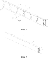
FIG. 1 is a perspective view of a battery according to an embodiment of the present disclosure. -
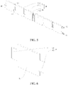
FIG. 2 is a three-dimensional view of the battery according to an embodiment of the present disclosure. -
FIG. 3 is a top view of the battery according to an embodiment of the present disclosure. -
FIG. 4 is a partial cross-sectional view of the battery according to an embodiment of the present disclosure. -
FIG. 5 is a partial three-dimensional structural view of the battery according to an embodiment of the present disclosure. -
FIG. 6 is a three-dimensional view of a metal connector and an insulating protector of the battery according to an embodiment of the present disclosure. - Reference Numerals:
-
Battery 1; -
Housing 10,Body 11,First electrode terminal 12,Second electrode terminal 13,First end cover 14,Second end cover 15, -
Battery core assembly 20,Electrode core assembly 21,Electrode core 212, -
First connector 30,Second connector 40, Metal connector a, Copper connection piece a1, Aluminum connection piece a2, Insulating protector b. - Embodiments of the present disclosure are described in detail below, and examples of the embodiments are shown in the accompanying drawings, where the same or similar elements or the elements having the same or similar functions are denoted by the same or similar reference numerals throughout the description. The embodiments described below with reference to the accompanying drawings are exemplary and used only for explaining the present disclosure, and should not be construed as a limitation on the present disclosure.
- A
battery 1 according to the embodiments of the present disclosure is described below with reference toFIG. 1 to FIG. 6 . - As shown in
FIG. 1 to FIG. 5 , thebattery 1 according to the embodiments of the present disclosure includes ahousing 10 and Mbattery core assemblies 20. Thebattery 1 is configured to provide power for operation of an electronic device, such as an electric vehicle. - Specifically, the M
battery core assemblies 20 are arranged in thehousing 10, and M≧2. It may be understood that, M is an integer. For example, M may be 2, 3, or 4, which is not enumerated herein. The Mbattery core assemblies 20 are stacked. The Mbattery core assemblies 20 are electrically connected. For example, twobattery core assemblies 20 are stacked. For another example, threebattery core assemblies 20 are stacked. Eachbattery core assembly 20 includes multipleelectrode core assemblies 21, and eachelectrode core assembly 21 includes at least oneelectrode core 212. The multipleelectrode core assemblies 21 in eachbattery core assembly 20 are connected in series. - It may be understood that, the stacked arrangement of the multiple
battery core assemblies 20 may be that the multiplebattery core assemblies 20 are connected in series, the multiplebattery core assemblies 20 are connected in parallel, or the multiple battery core assemblies are partly connected in series and partly connected in parallel. This is not limited in the present disclosure. Numbers of theelectrode core assemblies 21 in all of thebattery core assemblies 20 may be the same, or may be different, or may be partly the same and partly different. - For example, the
battery 1 includes twobattery core assemblies 20. The twobattery core assemblies 20 may be connected in series in sequence. Numbers ofelectrode core assemblies 21 in the twobattery core assemblies 20 may be the same or different. Alternatively, thebattery 1 includes twobattery core assemblies 20. The twobattery core assemblies 20 may be connected in parallel. Numbers ofelectrode core assemblies 21 in the twobattery core assemblies 20 may be the same or different. - For another example, the
battery 1 includes threebattery core assemblies 20. The threebattery core assemblies 20 may be connected in series in sequence. Numbers ofelectrode core assemblies 21 in all of the threebattery core assemblies 20 may be the same. Alternatively, numbers ofelectrode core assemblies 21 in two of the threebattery core assemblies 20 may be the same, and a number ofelectrode core assemblies 21 in the other one of thebattery core assemblies 20 may be different from the numbers of theelectrode core assemblies 21 in the two of thebattery core assemblies 20. Alternatively, thebattery 1 includes threebattery core assemblies 20. The threebattery core assemblies 20 are connected in parallel. Numbers ofelectrode core assemblies 21 in all of the threebattery core assemblies 20 may be the same. Alternatively, numbers ofelectrode core assemblies 21 in two of the threebattery core assemblies 20 may be the same, and a number ofelectrode core assemblies 21 in the other one of thebattery core assemblies 20 may be different from the numbers of theelectrode core assemblies 21 in the two of thebattery core assemblies 20. Alternatively, thebattery 1 includes threebattery core assemblies 20. Two of the threebattery core assemblies 20 are connected in parallel and then are connected in series with the other one of thebattery core assemblies 20. Numbers ofelectrode core assemblies 21 in all of the threebattery core assemblies 20 may be the same. Alternatively, numbers ofelectrode core assemblies 21 in two of the threebattery core assemblies 20 may be the same, and a number ofelectrode core assemblies 21 in the other one of thebattery core assemblies 20 may be different from the numbers of theelectrode core assemblies 21 in the two of thebattery core assemblies 20. - For another example, the
battery 1 includes fourbattery core assemblies 20. The fourbattery core assemblies 20 are connected in series in sequence. Numbers ofelectrode core assemblies 21 in all of thebattery core assemblies 20 may be the same. Alternatively, numbers ofelectrode core assemblies 21 in two of the fourbattery core assemblies 20 may be the same, and numbers ofelectrode core assemblies 21 in other two of thebattery core assemblies 20 may be the same or different. Alternatively, numbers ofelectrode core assemblies 21 in three of the fourbattery core assemblies 20 may be the same, and a number ofelectrode core assemblies 21 in the other one of thebattery core assemblies 20 may be different from the numbers of the electrode core assemblies in the three of the battery core assemblies. This is not enumerated in the present disclosure, and is not specifically limited. The above is merely used as an example. - It may be understood that, the numbers of the
electrode core assemblies 21 in all of the multiplebattery core assemblies 20 may be the same. In this way, not only arrangement regularity of the multiplebattery core assemblies 20 can be improved, but also the space utilization of thehousing 10 can be improved, thereby facilitating miniaturization of thebattery 1. However, this is not limited in the present disclosure. - In addition, the
housing 10 may be a metal housing or a housing made of a composite material. In some embodiments of the present disclosure, the housing is an aluminum housing, so that thehousing 10 can be lighter, can have moderate structural strength, and can be more economical. However, this is not limited in the present disclosure. - It should be further understood that the
electrode core 212 mentioned in the present disclosure is anelectrode core 212 frequently used in the field of power batteries, and theelectrode core 212 and theelectrode core assembly 21 are components inside thehousing 10 of thebattery 1, and cannot be understood as thebattery 1. Theelectrode core 212 may be formed by winding or lamination. Generally, theelectrode core 212 includes at least a positive plate, a separator, a negative plate, and an electrolyte solution. Theelectrode core 212 is generally an assembly that is not completely sealed. Therefore, thebattery 1 mentioned in the present disclosure is a cell, and cannot be simply understood as a battery module or a battery pack although the battery includesmultiple electrode cores 212. - It should be noted that one
electrode core assembly 21 may include oneelectrode core 212. Alternatively, theelectrode core assembly 21 may include at least twoelectrode cores 212, and the at least twoelectrode cores 212 are connected in parallel to form anelectrode core assembly 21. In addition, oneelectrode core assembly 21 may alternatively include threeelectrode cores 212 ormore electrode cores 212, which is not enumerated in the present disclosure. It can be understood from the above that, when eachbattery core assembly 20 includes multipleelectrode core assemblies 21, numbers ofelectrode cores 212 in all of theelectrode core assemblies 21 may be the same, or may be different, or may be partly the same and partly different. - In addition, the series connection between the
electrode core assemblies 21 in the present disclosure may be series connection between adjacentelectrode core assemblies 21. A specific implementation may be that current lead-out members on the adjacentelectrode core assemblies 21 are directly connected or electrically connected by an additional conductive member. That is to say, the two adjacentelectrode core assemblies 21 may be electrically connected directly or indirectly. - Specifically, according to an embodiment of the present disclosure, two
battery core assemblies 20 are arranged. Eachbattery core assembly 20 includes sixelectrode core assemblies 21. The sixelectrode core assemblies 21 are spaced apart and connected in series in a length direction of thehousing 10. Eachelectrode core assembly 21 includes oneelectrode core 212. - According to the
battery 1 in the embodiments of the present disclosure, Mbattery core assemblies 20 are arranged in ahousing 10, where M≥2, so thatmultiple electrode cores 212 can be arranged in thehousing 10. By integrating themultiple electrode cores 212, thebattery 1 can have a high capacity or a high voltage, a battery life of thebattery 1 can be increased, materials required for thehousing 10 are reduced, and overall manufacturing process difficulty and production costs of thebattery 1 are reduced. In addition, since themultiple electrode cores 212 are compactly arranged in thesame housing 10, an occupied space can be reduced while increasing the battery life of thebattery 1, thereby improving a space utilization. - According to some embodiments of the present disclosure, an electrode terminal configured to lead out a current is arranged on the
housing 10. The electrode terminal includes afirst electrode terminal 12 and asecond electrode terminal 13. Thefirst electrode terminal 12 and thesecond electrode terminal 13 are arranged on a same side of thehousing 10. Thefirst electrode terminal 12 and thesecond electrode terminal 13 are connected with an external device to provide power for operation of the external device. Thefirst electrode terminal 12 may be a positive electrode terminal, and thesecond electrode terminal 13 may be a negative electrode terminal. Alternatively, thefirst electrode terminal 12 may be a negative electrode terminal, and thesecond electrode terminal 13 may be a positive electrode terminal. Arranging thefirst electrode terminal 12 and thesecond electrode terminal 13 on the same side of thehousing 10 facilitates arrangement of conduction members between thebatteries 1 in a battery module when thebattery 1 is applicable to the battery module, and facilitates arrangement of power connection members between thebatteries 1 in a battery pack when thebattery 1 is applicable to the battery pack. - As shown in
FIG. 3 , according to some embodiments of the present disclosure, thehousing 10 includes abody 11 and two end covers. The two end covers are arranged on two opposite ends of thebody 11 to cover an inner space of thebody 11. The electrode terminal is arranged on one of the two end covers. Specifically, the two end covers are named as afirst end cover 14 and asecond end cover 15 respectively. The electrode terminal is arranged on thefirst end cover 14 or thesecond end cover 15. By arranging the positive electrode terminal and the electrode terminal on one end cover, costs can be reduced. - As shown in
FIG. 3 , thebody 11 is formed as an annular shape, and two ends of thebody 11 are open, so that thebattery core assembly 20 can be mounted in an annular cavity formed by thebody 11. Thefirst end cover 14 is arranged on thebody 11 to cover an opening on one end of thebody 11, and thesecond end cover 15 is arranged on thebody 11 to cover an opening on an other end of thebody 11. - It should be noted that the
first end cover 14, thesecond end cover 15, and thebody 11 may be integrally formed, so that assembly processes can be reduced and assembly efficiency can be improved. In addition, structural strength of thehousing 10 can be enhanced, thereby ensuring connection reliability of thehousing 10. Alternatively, thefirst end cover 14 is integrally formed with thebody 11, and thesecond end cover 15 is formed separately and then connected with and thebody 11. Alternatively, thefirst end cover 14, thesecond end cover 15, and thebody 11 are separately formed and then connected, so that processing difficulty of thehousing 10 can be reduced and production efficiency of thehousing 10 can be improved. - It may be understood that, when the electrode terminal is arranged on the
first end cover 14 and an odd number of battery core assemblies 20 (that is, M is an odd number) are arranged in thebattery 1, two of thebattery core assemblies 20 may be connected in parallel and then connected in series with the remainingbattery core assemblies 20. For example, when three battery core assemblies are arranged, two of thebattery core assemblies 20 may be connected in parallel and then connected in series with the other onebattery core assembly 20. Alternatively, M-1battery core assemblies 20 may be connected in parallel and then connected in series with the other onebattery core assembly 20. This is not enumerated in the present disclosure, and is not specifically limited. The above is merely used as an example. - According to some embodiments of the present disclosure, M is an even number. Each two adjacent
battery core assemblies 20 are connected in series. - By arranging both of the
first electrode terminal 12 and thesecond electrode terminal 13 on thefirst end cover 14 or thesecond end cover 15, thebattery 1 can achieve a high voltage output. - According to some embodiments of the present disclosure, two adjacent
battery core assemblies 20 are connected in parallel, so that thebattery 1 realizes a high-capacity output. - For example, as shown in
FIG. 5 , twoelectrode core assemblies 21 are arranged, and thefirst electrode terminal 12 and thesecond electrode terminal 13 are both arranged on thefirst end cover 14. In some embodiments of the present disclosure, thesecond end cover 15 is integrally formed with thebody 11, and thefirst end cover 14 is formed separately and then connected with thebody 11, so that processing steps and man-hours can be reduced, thereby reducing production costs. However, the present disclosure is not limited thereto. - Further, the multiple
electrode core assemblies 21 of thebattery core assembly 20 are arranged in sequence along a first direction. The first direction is a left-to-right direction shown inFIG. 1 . It should be noted that the first direction is a length direction of thebattery 1. Each of the multiple battery core assemblies has two opposite ends along the first direction. Two adjacentbattery core assemblies 20 are connected in series by twoelectrode core assemblies 21 located on a same end. In this way, connection difficulty of the two adjacentbattery core assemblies 20 is reduced, and a connection distance between the two adjacentbattery core assemblies 20 is shortened, so that connection efficiency is relatively improved, thereby reducing the costs. - According to some embodiments of the present disclosure, the multiple
electrode core assemblies 21 of thebattery core assembly 20 are arranged in sequence along the first direction. The first direction is the left-to-right direction shown inFIG. 1 . Eachelectrode core assembly 21 includes a first electrode lead-out member and a second electrode lead-out member configured to lead out a current. The first electrode lead-out member and the second electrode lead-out member are respectively arranged on two sides of theelectrode core assembly 21 along the first direction. It should be noted that the first direction is the length direction of thebattery 1. It should be further noted that, arranging the multipleelectrode core assemblies 21 in thebattery core assembly 20 in sequence along the first direction herein means arranging the multipleelectrode core assemblies 21 in the samebattery core assembly 20 along the first direction. - It may be understood that, each
electrode core assembly 21 is required to be connected in series to connect the multipleelectrode core assemblies 21 in series. By using the first electrode lead-out member and the second electrode lead-out member arranged on eachelectrode core assembly 21, series connection between the two adjacentelectrode core assemblies 21 can be realized. Moreover, the connection difficulty is relatively low, and the connection efficiency is relatively high. It may be understood that, in some embodiments, the first electrode lead-out member and the second electrode lead-out member are respectively a positive tab and a negative tab on an electrode core, but the present disclosure is not limited thereto. - For example, when an
electrode core assembly 21 includes only oneelectrode core 212, the first electrode lead-out member and the second electrode lead-out member may be respectively a positive tab and a negative tab of theelectrode core 212. When anelectrode core assembly 21 includesmultiple electrode cores 212, the first electrode lead-out member may be a positive lead-out terminal formed by combining and welding positive tabs of themultiple electrode cores 212 together, and the second electrode lead-out member may be a negative lead-out terminal formed by combining and welding negative tabs of themultiple electrode cores 212 together. Alternatively, the first electrode lead-out member may be the negative lead-out terminal formed by welding the negative tabs of themultiple electrode cores 212 together, and the second electrode lead-out member may be the positive lead-out terminal formed by combining and welding positive tabs of themultiple electrode cores 212 together. - It should be noted that "first" of the first electrode lead-out member and "second" of the second electrode lead-out member are merely used to distinguish between names, and are not used to limit a quantity.
- According to some embodiments of the present disclosure, the multiple
electrode core assemblies 21 of thebattery core assembly 20 are arranged in sequence along the first direction. The first direction is the left-to-right direction shown inFIG. 1 . Theelectrode core assembly 21 includes a first electrode lead-out member and a second electrode lead-out member configured to lead out a current. The first electrode lead-out member and the second electrode lead-out member are respectively arranged on the two sides of theelectrode core assembly 21 along the first direction. Each of the multiplebattery core assemblies 20 has a first end and a second end opposite to each other along the first direction. Thefirst electrode terminal 12 and thesecond electrode terminal 13 are arranged on a same end cover, that is, are both arranged on the first end or on the second end. When M is an even number, each two adjacentbattery core assemblies 20 are connected in series by twoelectrode core assemblies 21 located on the first end or twoelectrode core assemblies 21 located on the second end 22. It may be understood that, an arrangement direction of the first electrode lead-out members and the second electrode lead-out members in eachbattery core assembly 20 is opposite to an arrangement direction of the first electrode lead-out members and the second electrode lead-out members in an adjacentbattery core assembly 20. For example, when M is 2, the arrangement direction of the first electrode lead-out members and the second electrode lead-out members in one of thebattery core assemblies 20 is opposite to the arrangement direction of the first electrode lead-out members and the second electrode lead-out members in the other of thebattery core assemblies 20. When M is an odd number, an arrangement direction of the first electrode lead-out members and the second electrode lead-out members in at least one of thebattery core assemblies 20 is opposite to an arrangement direction of the first electrode lead-out members and the second electrode lead-out members in an adjacentbattery core assembly 20. For example, when M is 3, the arrangement directions of the first electrode lead-out members and the second electrode lead-out members in two adjacent ones of thebattery core assemblies 20 are the same, and are opposite to the arrangement direction of the first electrode lead-out members and the second electrode lead-out members in the other one of thebattery core assemblies 20. - Further, each two adjacent
electrode core assemblies 21 in thebattery core assembly 20 are connected in series by afirst connector 30, thereby realizing series connection of the multipleelectrode core assemblies 21. Each two adjacentbattery core assemblies 20 are connected in series by asecond connector 40, thereby realizing series connection of the multiplebattery core assemblies 20. Thefirst connector 30 and thesecond connector 40 are both electrically conductive, and specific structures thereof are configured according to actual requirements. - Further, as shown in
FIG. 6 , at least one of thefirst connector 30 or thesecond connector 40 includes a metal connector a and an insulating protector b. Two ends of the metal connector a are respectively connected with two adjacentelectrode core assemblies 21, thereby realizing series connection of the twoelectrode core assemblies 21. The insulating protector b is sleeved on the metal connector a, so that structural strength of the metal connector a can be improved, and safe insulation is realized, thereby reducing a possibility of electric leakage of the metal connector a. - Further, As shown in
FIG. 5 and FIG. 6 , theelectrode core assembly 21 includes the first electrode lead-out member and the second electrode lead-out member configured to lead out a current. The first electrode lead-out member is configured as a negative lead-out member, and the second electrode lead-out member is configured as a positive lead-out member. The metal connector a includes a copper connection piece a1 and an aluminum connection piece a2. The copper connection piece a1 is connected with the first electrode lead-out member, and the aluminum connection piece a2 is connected with the second electrode lead-out member. One end of the copper connection piece a1 is connected with one end of the aluminum connection piece a2. The insulating protector b is wrapped around a joint of the copper connection piece a1 and the aluminum connection piece a2. Currently, in a commonly-usedelectrode core 212, a copper structural member is generally adopted as a negative lead-out terminal, because the copper structural member is set at a low potential so that lithium embedding is not readily achievable; a second electrode lead-out member is a positive lead-out terminal, and an aluminum structural member is generally adopted as the positive lead-out terminal of the commonly-usedelectrode core 212, because a surface of the aluminum structural member has an oxide layer which is set at a high potential so that the positive lead-out terminal is not easily oxidized. An other end of the copper connection piece a1 is connected with the copper structure of one of two adjacentelectrode core assemblies 21, and an other end of the aluminum connection piece a2 is connected with the aluminum structure of the other of the twoadjacent electrode cores 212, Therefore, when arranging the metal connector a, a structure of the metal connector a may be configured as matching a structure of the existingelectrode core 212, so that connection reliability of the metal connector a and theelectrode cores 212 can be enhanced. - Further, the copper connection piece a1 and the aluminum connection piece a2 are connected by welding, thereby realizing series connection of two
adjacent electrode cores 212. - Further, the insulating protector b is sleeved on the metal connector a by a plastic dipping process, a thermal shrinkage process, a spraying process, or a hot-melting process, so that a possibility that the insulating protector b falls off the metal connector a can be reduced, and a gap between the insulating protector b and the metal connector a can be reduced to a larger extent, thereby reducing a possibility of electric leakage caused by contact of the metal connector a with the
housing 10 when thehousing 10 is ametal housing 10. - According to some embodiments of the present disclosure, numbers of
electrode cores 212 in all of theelectrode core assemblies 21 are the same, so that the space utilization of thehousing 10 can be improved to a larger extent. - According to some embodiments of the present disclosure, the
battery core assembly 20 further includes multiple insulating films wrapped around the multipleelectrode core assemblies 21 in a one-to-one correspondence. In this way, theelectrode core assemblies 21 can be insulated from thehousing 10, thereby reducing a possibility of a short circuit inside thebattery 1. In addition, an insulating film is arranged on an outside of eachelectrode core assembly 21. An electrolyte solution may be filled into the insulating film, so that theelectrode core assemblies 21 do not share an electrolyte solution. In this way, a possibility of a short circuit inside thebattery 1 is reduced, and the electrolyte solution does not decompose as a result of a potential difference. The insulating film needs to have a certain insulativity and resistance to corrosion by the electrolyte solution. A material of the insulating film is not specially limited, as long as the insulating film does not react with the electrolyte solution. For example, the material of the insulating film may include a polypropylene (PP) film or a polyethylene (PE) film. - The battery module according to the embodiments of the present disclosure includes the
battery 1 described above. - In some embodiments of the present disclosure, a communication terminal is further arranged on the
housing 10. The communication terminal is electrically connected with eachelectrode core assembly 21. The communication terminal may be configured to detect status information (for example, a voltage and a temperature) of eachelectrode core assembly 21. Safety and stability are extremely vital for thebattery 1. In the related art,independent batteries 1 are connected in series/parallel to form a battery module or a battery pack. Therefore, eachbattery 1 can be sampled outside thebattery 1. However, if multipleelectrode core assemblies 21 are arranged in series inside thehousing 10 of thebattery 1, an operating status of eachelectrode core assembly 21 cannot be monitored during sampling outside thebattery 1. By arranging the communication terminal electrically connected to eachelectrode core assembly 21, eachelectrode core assembly 21 inside thehousing 10 can be sampled to monitor the status of eachelectrode core assembly 21, thereby ensuring the safety and stability of thebattery 1. - The battery module according to the embodiments of the present disclosure includes the
above battery 1 with a high capacity or a high voltage, so that not only a battery life of the battery module can be increased, but also a number ofbatteries 1 in the battery module can be reduced while a battery module with the same capacity and voltage can be obtained, thereby reducing conduction members at joints of batteries. In this way, costs of the battery module are reduced, and a space occupied by the conduction members in the battery module is reduced. In addition, since the conduction members are reduced, an internal resistance of the battery module is reduced, thereby increasing the battery life of the battery module. - The battery pack according to the embodiments of the present disclosure includes the battery or the battery module described above.
- The battery pack according to the embodiments of the present disclosure includes the battery or the battery module described above, so that not only a battery life of the battery pack can be increased, but also a number of battery modules in the battery pack can be reduced while a battery module with the same capacity and voltage can be obtained, thereby reducing power connectors at joints of battery modules. In this way, production costs of the battery pack are reduced, a production process of the battery pack is simplified, and a space occupied by the power connectors in the battery pack is reduced. In addition, since the power connectors are reduced, an internal resistance of the battery pack is reduced, so that internal consumption of the battery pack during use is reduced, thereby increasing the battery life of the battery pack.
- The electric vehicle according to the embodiments of the present disclosure includes the battery pack described above.
- The electric vehicle according to the embodiments of the present disclosure includes the battery pack described above, so that an internal structure of the electric vehicle can be more compact, and internal consumption of the battery pack during use can be reduced, so that a battery life of the battery pack is increased, use experience of the electric vehicle is enhanced, energy is saved, and use costs are reduced, thereby enhancing user experience.
- In the description of the present disclosure, it should be understood that orientation or position relationships indicated by the terms such as "center", "longitudinal", "transverse", "length", "width", "thickness", "on", "below", "front", "back", "left", "right", "vertical", "horizontal", "top", "bottom", "inside", "outside", "clockwise", "anticlockwise", "axial direction", "radial direction", and "circumferential direction" are based on orientation or position relationships shown in the accompanying drawings, and are used only for ease and brevity of illustration and description, rather than indicating or implying that the mentioned apparatus or component must have a particular orientation or must be constructed and operated in a particular orientation. Therefore, such terms should not be construed as limiting of the present disclosure. In addition, a feature defined to be "first" or "second" may explicitly or implicitly include one or more features. In the description of the present disclosure, unless otherwise stated, "a plurality of" means two or more than two.
- In the descriptions of this specification, descriptions using reference terms "an embodiment", "some embodiments", "an exemplary embodiment", "an example", "a specific example", or "some examples" mean that specific characteristics, structures, materials, or features described with reference to the embodiment or example are included in at least one embodiment or example of the present disclosure. In this specification, schematic descriptions of the foregoing terms do not necessarily point at a same embodiment or example. In addition, the described specific features, structures, materials, or characteristics may be combined in a proper manner in any one or more of the embodiments or examples.
- Although the embodiments of the present disclosure have been shown and described, persons of ordinary skill in the art should understand that various changes, modifications, replacements and variations may be made to the embodiments without departing from the principles and spirit of the present disclosure, and the scope of the present disclosure is as defined by the appended claims and their equivalents.
Claims (13)
- A battery, comprising:a housing; andM battery core assemblies arranged in the housing, wherein M≥2, the M battery core assemblies are stacked and are electrically connected, and each comprise a plurality of electrode core assemblies; and the plurality of electrode core assemblies in each battery core assembly are connected in series.
- The battery according to claim 1, wherein an electrode terminal configured to lead out a current is arranged on the housing; the electrode terminal comprises a first electrode terminal and a second electrode terminal; and the first electrode terminal and the second electrode terminal are arranged on a same side of the housing.
- The battery according to claim 2, wherein the housing comprises a body and two end covers arranged on two opposite ends of the body to cover an inner space of the body; and the electrode terminal is arranged on one of the two end covers.
- The battery according to any of claims 1 to 3, wherein M is an even number; and each two adjacent battery core assemblies are connected in series.
- The battery according to claim 4, wherein the plurality of electrode core assemblies in the battery core assembly are arranged in sequence along a first direction; the battery core assembly has two opposite ends along the first direction; and two adjacent battery core assemblies are connected in series by two electrode core assemblies located on a same end.
- The battery according to any of claims 1 to 5, wherein the plurality of electrode core assemblies in the battery core assembly are arranged in sequence along the first direction; each electrode core assembly comprises a first electrode lead-out member and a second electrode lead-out member configured to lead out a current; and the first electrode lead-out member and the second electrode lead-out member are respectively arranged on two sides of the electrode core assembly along the first direction.
- The battery according to any of claims 1 to 6, wherein each two adjacent electrode core assemblies in the battery core assembly are connected in series by a first connector; and each two adjacent battery core assemblies are connected in series by a second connector.
- The battery according to claim 7, wherein at least one of the first connector or the second connector comprises:a metal connector, wherein two ends of the metal connector are respectively connected with two adjacent electrode core assemblies; andan insulating protector, sleeved on the metal connector.
- The battery according to claim 8, wherein the electrode core assembly comprises a first electrode lead-out member and a second electrode lead-out member configured to lead out a current; the first electrode lead-out member is configured as a negative lead-out member; the second electrode lead-out member is configured as a positive lead-out member; the metal connector comprises a copper connection piece and an aluminum connection piece connected with the copper connection piece; the copper connection piece is connected with the first electrode lead-out member; the aluminum connection piece is connected with the second electrode lead-out member; and the insulating protector is wrapped around a joint of the copper connection piece and the aluminum connection piece.
- The battery according to any of claims 1 to 9, wherein the battery core assembly further comprises a plurality of insulating films wrapped around the plurality of electrode core assemblies in a one-to-one correspondence.
- A battery module, comprising the battery according to any of claims 1 to 10.
- A battery pack, comprising the battery according to any of claims 1 to 10 or the battery module according to claim 11.
- An electric vehicle, comprising the battery pack according to claim 12.
Applications Claiming Priority (2)
| Application Number | Priority Date | Filing Date | Title |
|---|---|---|---|
| CN202020059425.0U CN211208560U (en) | 2020-01-10 | 2020-01-10 | Battery, battery module, battery pack and electric vehicle |
| PCT/CN2021/070319 WO2021139649A1 (en) | 2020-01-10 | 2021-01-05 | Battery, battery module, battery pack, and electric vehicle |
Publications (1)
| Publication Number | Publication Date |
|---|---|
| EP4086979A1 true EP4086979A1 (en) | 2022-11-09 |
Family
ID=71852223
Family Applications (1)
| Application Number | Title | Priority Date | Filing Date |
|---|---|---|---|
| EP21738443.7A Pending EP4086979A1 (en) | 2020-01-10 | 2021-01-05 | Battery, battery module, battery pack, and electric vehicle |
Country Status (6)
| Country | Link |
|---|---|
| US (1) | US20230052047A1 (en) |
| EP (1) | EP4086979A1 (en) |
| JP (1) | JP2023509216A (en) |
| KR (1) | KR20220124770A (en) |
| CN (1) | CN211208560U (en) |
| WO (1) | WO2021139649A1 (en) |
Families Citing this family (4)
| Publication number | Priority date | Publication date | Assignee | Title |
|---|---|---|---|---|
| CN211208560U (en) * | 2020-01-10 | 2020-08-07 | 比亚迪股份有限公司 | Battery, battery module, battery pack and electric vehicle |
| CN114361629B (en) * | 2020-09-27 | 2023-08-08 | 比亚迪股份有限公司 | Battery, battery pack and electric vehicle |
| CN114267915B (en) * | 2021-11-29 | 2023-04-18 | 三一重工股份有限公司 | Battery box and vehicle |
| CN114976444A (en) * | 2022-06-28 | 2022-08-30 | 安徽舟之航电池有限公司 | City wall module for battery system |
Family Cites Families (4)
| Publication number | Priority date | Publication date | Assignee | Title |
|---|---|---|---|---|
| JP6315269B2 (en) * | 2014-08-22 | 2018-04-25 | 株式会社デンソー | Sealed battery module and manufacturing method thereof |
| CN110518156B (en) * | 2019-10-23 | 2020-03-20 | 比亚迪股份有限公司 | Lithium ion battery, battery module, battery pack and automobile |
| CN112701412A (en) * | 2019-10-23 | 2021-04-23 | 比亚迪股份有限公司 | Battery, battery module, battery pack and electric vehicle |
| CN211208560U (en) * | 2020-01-10 | 2020-08-07 | 比亚迪股份有限公司 | Battery, battery module, battery pack and electric vehicle |
-
2020
- 2020-01-10 CN CN202020059425.0U patent/CN211208560U/en active Active
-
2021
- 2021-01-05 KR KR1020227027238A patent/KR20220124770A/en unknown
- 2021-01-05 US US17/791,136 patent/US20230052047A1/en active Pending
- 2021-01-05 WO PCT/CN2021/070319 patent/WO2021139649A1/en unknown
- 2021-01-05 JP JP2022542271A patent/JP2023509216A/en active Pending
- 2021-01-05 EP EP21738443.7A patent/EP4086979A1/en active Pending
Also Published As
| Publication number | Publication date |
|---|---|
| CN211208560U (en) | 2020-08-07 |
| KR20220124770A (en) | 2022-09-14 |
| JP2023509216A (en) | 2023-03-07 |
| US20230052047A1 (en) | 2023-02-16 |
| WO2021139649A1 (en) | 2021-07-15 |
Similar Documents
| Publication | Publication Date | Title |
|---|---|---|
| EP4086979A1 (en) | Battery, battery module, battery pack, and electric vehicle | |
| KR101695868B1 (en) | Electrode block, layered battery, and assembly method for layered battery | |
| EP2426751B1 (en) | Rechargeable battery | |
| EP4050709A1 (en) | Battery, battery module, battery pack and electric vehicle | |
| CN101662038B (en) | Battery pack | |
| EP4050689A1 (en) | Battery, battery module, battery pack, and electric vehicle | |
| KR102020757B1 (en) | Electrical energy storage module and method for producing an electrical energy storage module | |
| CN218414641U (en) | End cover assembly, battery and electric equipment | |
| US20090029246A1 (en) | Pouch-type secondary battery | |
| KR101652653B1 (en) | Battery module and battery pack | |
| CN114039080B (en) | Electricity core, battery and power consumption device | |
| CN112838333A (en) | Battery, battery module, battery pack and automobile | |
| JP4955399B2 (en) | Film exterior electrical device assembly | |
| CN113140851A (en) | Lithium ion battery module | |
| KR101783914B1 (en) | Pouch type secondary battery and battery pack including the same | |
| JP7420940B2 (en) | Batteries, battery modules, battery packs and electric vehicles | |
| CN114361732A (en) | Electrochemical device and electronic apparatus | |
| KR20220139359A (en) | Batteries, battery modules, battery packs, and electric vehicles | |
| CN114361661A (en) | Square shell battery cell and battery module | |
| CN218101548U (en) | Battery and electric equipment | |
| JP2019200986A (en) | Cell and cell system | |
| CN219180722U (en) | Battery and electric equipment | |
| CN216903439U (en) | Connecting device, battery and electric equipment | |
| CN215644895U (en) | Battery and battery pack | |
| US20230133112A1 (en) | Electrochemical device and electrical device |
Legal Events
| Date | Code | Title | Description |
|---|---|---|---|
| STAA | Information on the status of an ep patent application or granted ep patent |
Free format text: STATUS: THE INTERNATIONAL PUBLICATION HAS BEEN MADE |
|
| PUAI | Public reference made under article 153(3) epc to a published international application that has entered the european phase |
Free format text: ORIGINAL CODE: 0009012 |
|
| STAA | Information on the status of an ep patent application or granted ep patent |
Free format text: STATUS: REQUEST FOR EXAMINATION WAS MADE |
|
| 17P | Request for examination filed |
Effective date: 20220802 |
|
| AK | Designated contracting states |
Kind code of ref document: A1 Designated state(s): AL AT BE BG CH CY CZ DE DK EE ES FI FR GB GR HR HU IE IS IT LI LT LU LV MC MK MT NL NO PL PT RO RS SE SI SK SM TR |
|
| DAV | Request for validation of the european patent (deleted) | ||
| DAX | Request for extension of the european patent (deleted) |