EP4086751A1 - Steuerung durch wischen auf virtuellen schaltflächen - Google Patents
Steuerung durch wischen auf virtuellen schaltflächen Download PDFInfo
- Publication number
- EP4086751A1 EP4086751A1 EP22170136.0A EP22170136A EP4086751A1 EP 4086751 A1 EP4086751 A1 EP 4086751A1 EP 22170136 A EP22170136 A EP 22170136A EP 4086751 A1 EP4086751 A1 EP 4086751A1
- Authority
- EP
- European Patent Office
- Prior art keywords
- predefined
- microphones
- slip
- audio reproduction
- microphone
- Prior art date
- Legal status (The legal status is an assumption and is not a legal conclusion. Google has not performed a legal analysis and makes no representation as to the accuracy of the status listed.)
- Granted
Links
Images

Classifications
-
- G—PHYSICS
- G06—COMPUTING OR CALCULATING; COUNTING
- G06F—ELECTRIC DIGITAL DATA PROCESSING
- G06F3/00—Input arrangements for transferring data to be processed into a form capable of being handled by the computer; Output arrangements for transferring data from processing unit to output unit, e.g. interface arrangements
- G06F3/16—Sound input; Sound output
- G06F3/165—Management of the audio stream, e.g. setting of volume, audio stream path
-
- H—ELECTRICITY
- H04—ELECTRIC COMMUNICATION TECHNIQUE
- H04R—LOUDSPEAKERS, MICROPHONES, GRAMOPHONE PICK-UPS OR LIKE ACOUSTIC ELECTROMECHANICAL TRANSDUCERS; ELECTRIC HEARING AIDS; PUBLIC ADDRESS SYSTEMS
- H04R3/00—Circuits for transducers
- H04R3/005—Circuits for transducers for combining the signals of two or more microphones
-
- G—PHYSICS
- G06—COMPUTING OR CALCULATING; COUNTING
- G06F—ELECTRIC DIGITAL DATA PROCESSING
- G06F3/00—Input arrangements for transferring data to be processed into a form capable of being handled by the computer; Output arrangements for transferring data from processing unit to output unit, e.g. interface arrangements
- G06F3/01—Input arrangements or combined input and output arrangements for interaction between user and computer
- G06F3/03—Arrangements for converting the position or the displacement of a member into a coded form
- G06F3/033—Pointing devices displaced or positioned by the user, e.g. mice, trackballs, pens or joysticks; Accessories therefor
- G06F3/0354—Pointing devices displaced or positioned by the user, e.g. mice, trackballs, pens or joysticks; Accessories therefor with detection of two-dimensional [2D] relative movements between the device, or an operating part thereof, and a plane or surface, e.g. 2D mice, trackballs, pens or pucks
- G06F3/03547—Touch pads, in which fingers can move on a surface
-
- G—PHYSICS
- G06—COMPUTING OR CALCULATING; COUNTING
- G06F—ELECTRIC DIGITAL DATA PROCESSING
- G06F3/00—Input arrangements for transferring data to be processed into a form capable of being handled by the computer; Output arrangements for transferring data from processing unit to output unit, e.g. interface arrangements
- G06F3/01—Input arrangements or combined input and output arrangements for interaction between user and computer
- G06F3/03—Arrangements for converting the position or the displacement of a member into a coded form
- G06F3/041—Digitisers, e.g. for touch screens or touch pads, characterised by the transducing means
- G06F3/043—Digitisers, e.g. for touch screens or touch pads, characterised by the transducing means using propagating acoustic waves
- G06F3/0436—Digitisers, e.g. for touch screens or touch pads, characterised by the transducing means using propagating acoustic waves in which generating transducers and detecting transducers are attached to a single acoustic waves transmission substrate
-
- G—PHYSICS
- G06—COMPUTING OR CALCULATING; COUNTING
- G06F—ELECTRIC DIGITAL DATA PROCESSING
- G06F3/00—Input arrangements for transferring data to be processed into a form capable of being handled by the computer; Output arrangements for transferring data from processing unit to output unit, e.g. interface arrangements
- G06F3/01—Input arrangements or combined input and output arrangements for interaction between user and computer
- G06F3/048—Interaction techniques based on graphical user interfaces [GUI]
- G06F3/0484—Interaction techniques based on graphical user interfaces [GUI] for the control of specific functions or operations, e.g. selecting or manipulating an object, an image or a displayed text element, setting a parameter value or selecting a range
- G06F3/04847—Interaction techniques to control parameter settings, e.g. interaction with sliders or dials
-
- G—PHYSICS
- G06—COMPUTING OR CALCULATING; COUNTING
- G06F—ELECTRIC DIGITAL DATA PROCESSING
- G06F3/00—Input arrangements for transferring data to be processed into a form capable of being handled by the computer; Output arrangements for transferring data from processing unit to output unit, e.g. interface arrangements
- G06F3/01—Input arrangements or combined input and output arrangements for interaction between user and computer
- G06F3/048—Interaction techniques based on graphical user interfaces [GUI]
- G06F3/0487—Interaction techniques based on graphical user interfaces [GUI] using specific features provided by the input device, e.g. functions controlled by the rotation of a mouse with dual sensing arrangements, or of the nature of the input device, e.g. tap gestures based on pressure sensed by a digitiser
- G06F3/0488—Interaction techniques based on graphical user interfaces [GUI] using specific features provided by the input device, e.g. functions controlled by the rotation of a mouse with dual sensing arrangements, or of the nature of the input device, e.g. tap gestures based on pressure sensed by a digitiser using a touch-screen or digitiser, e.g. input of commands through traced gestures
-
- G—PHYSICS
- G06—COMPUTING OR CALCULATING; COUNTING
- G06F—ELECTRIC DIGITAL DATA PROCESSING
- G06F3/00—Input arrangements for transferring data to be processed into a form capable of being handled by the computer; Output arrangements for transferring data from processing unit to output unit, e.g. interface arrangements
- G06F3/01—Input arrangements or combined input and output arrangements for interaction between user and computer
- G06F3/048—Interaction techniques based on graphical user interfaces [GUI]
- G06F3/0487—Interaction techniques based on graphical user interfaces [GUI] using specific features provided by the input device, e.g. functions controlled by the rotation of a mouse with dual sensing arrangements, or of the nature of the input device, e.g. tap gestures based on pressure sensed by a digitiser
- G06F3/0488—Interaction techniques based on graphical user interfaces [GUI] using specific features provided by the input device, e.g. functions controlled by the rotation of a mouse with dual sensing arrangements, or of the nature of the input device, e.g. tap gestures based on pressure sensed by a digitiser using a touch-screen or digitiser, e.g. input of commands through traced gestures
- G06F3/04883—Interaction techniques based on graphical user interfaces [GUI] using specific features provided by the input device, e.g. functions controlled by the rotation of a mouse with dual sensing arrangements, or of the nature of the input device, e.g. tap gestures based on pressure sensed by a digitiser using a touch-screen or digitiser, e.g. input of commands through traced gestures for inputting data by handwriting, e.g. gesture or text
-
- G—PHYSICS
- G06—COMPUTING OR CALCULATING; COUNTING
- G06F—ELECTRIC DIGITAL DATA PROCESSING
- G06F3/00—Input arrangements for transferring data to be processed into a form capable of being handled by the computer; Output arrangements for transferring data from processing unit to output unit, e.g. interface arrangements
- G06F3/01—Input arrangements or combined input and output arrangements for interaction between user and computer
- G06F3/048—Interaction techniques based on graphical user interfaces [GUI]
- G06F3/0487—Interaction techniques based on graphical user interfaces [GUI] using specific features provided by the input device, e.g. functions controlled by the rotation of a mouse with dual sensing arrangements, or of the nature of the input device, e.g. tap gestures based on pressure sensed by a digitiser
- G06F3/0488—Interaction techniques based on graphical user interfaces [GUI] using specific features provided by the input device, e.g. functions controlled by the rotation of a mouse with dual sensing arrangements, or of the nature of the input device, e.g. tap gestures based on pressure sensed by a digitiser using a touch-screen or digitiser, e.g. input of commands through traced gestures
- G06F3/04886—Interaction techniques based on graphical user interfaces [GUI] using specific features provided by the input device, e.g. functions controlled by the rotation of a mouse with dual sensing arrangements, or of the nature of the input device, e.g. tap gestures based on pressure sensed by a digitiser using a touch-screen or digitiser, e.g. input of commands through traced gestures by partitioning the display area of the touch-screen or the surface of the digitising tablet into independently controllable areas, e.g. virtual keyboards or menus
-
- G—PHYSICS
- G06—COMPUTING OR CALCULATING; COUNTING
- G06F—ELECTRIC DIGITAL DATA PROCESSING
- G06F3/00—Input arrangements for transferring data to be processed into a form capable of being handled by the computer; Output arrangements for transferring data from processing unit to output unit, e.g. interface arrangements
- G06F3/16—Sound input; Sound output
- G06F3/167—Audio in a user interface, e.g. using voice commands for navigating, audio feedback
-
- H—ELECTRICITY
- H04—ELECTRIC COMMUNICATION TECHNIQUE
- H04R—LOUDSPEAKERS, MICROPHONES, GRAMOPHONE PICK-UPS OR LIKE ACOUSTIC ELECTROMECHANICAL TRANSDUCERS; ELECTRIC HEARING AIDS; PUBLIC ADDRESS SYSTEMS
- H04R5/00—Stereophonic arrangements
- H04R5/02—Spatial or constructional arrangements of loudspeakers
-
- G—PHYSICS
- G06—COMPUTING OR CALCULATING; COUNTING
- G06F—ELECTRIC DIGITAL DATA PROCESSING
- G06F2200/00—Indexing scheme relating to G06F1/04 - G06F1/32
- G06F2200/16—Indexing scheme relating to G06F1/16 - G06F1/18
- G06F2200/163—Indexing scheme relating to constructional details of the computer
- G06F2200/1636—Sensing arrangement for detection of a tap gesture on the housing
-
- G—PHYSICS
- G06—COMPUTING OR CALCULATING; COUNTING
- G06F—ELECTRIC DIGITAL DATA PROCESSING
- G06F2203/00—Indexing scheme relating to G06F3/00 - G06F3/048
- G06F2203/033—Indexing scheme relating to G06F3/033
- G06F2203/0339—Touch strips, e.g. orthogonal touch strips to control cursor movement or scrolling; single touch strip to adjust parameter or to implement a row of soft keys
-
- G—PHYSICS
- G06—COMPUTING OR CALCULATING; COUNTING
- G06F—ELECTRIC DIGITAL DATA PROCESSING
- G06F2203/00—Indexing scheme relating to G06F3/00 - G06F3/048
- G06F2203/041—Indexing scheme relating to G06F3/041 - G06F3/045
- G06F2203/04103—Manufacturing, i.e. details related to manufacturing processes specially suited for touch sensitive devices
-
- H—ELECTRICITY
- H04—ELECTRIC COMMUNICATION TECHNIQUE
- H04R—LOUDSPEAKERS, MICROPHONES, GRAMOPHONE PICK-UPS OR LIKE ACOUSTIC ELECTROMECHANICAL TRANSDUCERS; ELECTRIC HEARING AIDS; PUBLIC ADDRESS SYSTEMS
- H04R2205/00—Details of stereophonic arrangements covered by H04R5/00 but not provided for in any of its subgroups
- H04R2205/024—Positioning of loudspeaker enclosures for spatial sound reproduction
Definitions
- the invention relates to the field of audio reproduction equipment comprising at least one loudspeaker and microphones.
- Some recent electronic equipment incorporate not only one or more loudspeakers to reproduce audio signals, but also one or more microphones to capture sound signals, and are capable of interacting with the user by voice. This equipment can thus acquire commands emitted orally by the user, and respond by emitting sound signals intended for the user.
- connected speakers are known which can be used to implement the voice recognition method of a virtual personal assistant.
- decoder boxes or set-top boxes in English which incorporate a voice assistance device.
- Such equipment conventionally carries out a method of forming channels which allows it to focus the direction in which it is listening and to ignore sounds coming from a direction other than that of the user (we speak of " beamforming " in English) .
- the channel forming process requires multiple microphones.
- Such equipment also generally includes one or more buttons allowing quick access to certain functions: start of voice interaction with the user, activation or deactivation of standby mode, on/off, volume adjustment, Bluetooth pairing, etc
- the object of the invention is to reduce the cost of audio reproduction equipment as previously described and to improve the user's interactions with said audio reproduction equipment.
- the audio reproduction equipment therefore comprises “virtual buttons”, which each comprise a microphone and a hole via which the microphone communicates with the outside.
- the virtual buttons allow the user to command predetermined actions by sliding his finger on the casing of the audio reproduction equipment.
- the detection carried out depends neither on the characteristics of the finger (and in particular on the length of the fingernail) nor on a force with which the finger would tap on the box.
- the detection does not require a particular level of ambient noise, and therefore works even if the environment is completely silent.
- the sliding control is particularly suitable for actions with a progressive response, such as for example the adjustment of the volume of sound reproduction.
- the interactions between the user and the audio reproduction equipment are therefore improved.
- Audio reproduction equipment is also proposed as previously described, the processing component being arranged to compare the command slip with at least one predefined slip from a predefined list, to determine a particular predefined slip to which the command slip corresponds, and to command at least one predetermined action associated with the particular predefined slip.
- each predefined sliding corresponds to a succession of predefined occultations of microphones arranged successively.
- At least one slide predefined associated with a particular predetermined action is defined so as to necessarily begin with a muting of a predefined initial microphone and/or so as to necessarily end with a muting of a predefined final microphone.
- the predefined list comprises several predefined slides in the same direction but of different lengths.
- the predefined slips comprise predefined slips in a first direction and predefined slips in a second direction, a predefined slip in the first direction being associated with an increase of a response level of the step-response action whereas a predefined slip in the second direction is associated with a reduction in the response level of the step-response action.
- audio restitution equipment comprising a sensory transmitter arranged to provide the user with sensory feedback representative of the control slip and/or of a response level of the predetermined action.
- the sensory transmitter is arranged to emit a feedback sensory signal which depends on a path on the housing of a finger of the user during the control slip .
- the sensory transmitter being a light transmitter.
- the sensory transmitter being a sound transmitter.
- a computer program is also proposed comprising instructions which lead the processing component of the audio reproduction equipment as previously described to execute the steps of the control method as previously described.
- a computer-readable recording medium is also proposed, on which the computer program which has just been described is recorded.
- the audio reproduction equipment is here a connected speaker 1 which is used to implement the voice recognition method of a virtual personal assistant.
- the connected speaker 1 firstly comprises a box 2.
- box is meant here the physical envelope inside which are integrated the functional components of the connected speaker 1 which will be described.
- the box 2 can comprise several parts and possibly one or possibly removable covers.
- the casing 2 can comprise one or more rigid, flexible, metal, plastic, fabric, foam, etc. parts.
- the box 2 further comprises feet 3 which rest on any support (for example a table or any piece of furniture) when the connected speaker 1 is in its nominal operating position, as is the case on the figure 1 .
- the connected speaker 1 also includes an internal chassis (not shown in the figures) integrated inside the box 2.
- the connected speaker 1 further comprises an electric card 4.
- the electric card 4 is integrated into the casing 2 by being fixed to the internal chassis.
- the electrical card 4 is positioned parallel to the upper face 5 of the casing 2 and close to the latter.
- the distance between the electrical card 4 and the upper face 5 of the housing 2 is for example between 5mm and 1.5cm.
- the connected speaker 1 further comprises a loudspeaker 6 integrated into the casing 2 by being fixed to the internal frame.
- the loudspeaker 6 "points downwards", that is to say it has a directivity diagram which, when the connected loudspeaker 1 is in its nominal operating position, is oriented towards the down.
- a plurality of holes 7 are formed on the upper face 5 of the casing 2 (a single hole is shown on the figure 1 ). Each hole 7 passes through the casing 2.
- holes 7 could also be formed on the side faces of the casing 2, that is to say on the sides of the casing 2, and on any parts of the casing 2 (for example on a removable cover).
- the connected speaker 1 further comprises a plurality of microphones 10 (a single microphone 10 is shown on the figure 1 ) which here are surface mounted components (SMD).
- the microphones 10 are mounted on the printed circuit of the electrical card 4.
- Each microphone 10 is positioned inside the casing 2 and is close to a hole 7 (separate), so that the sensitive part of said microphone 10 is in acoustic communication with the outside via said hole 7.
- each microphone 10 is positioned opposite a hole 7 so that the axis of the hole 7 passes through the center of the microphone 10.
- the directivity diagram of loudspeaker 6 is oriented towards an area that does not include a microphone 10: the microphones 10 are in fact positioned here in an upper part of the connected speaker 1.
- a sound-insulating material is placed around each microphone 10 between the electrical card 4 and the casing 2.
- the sound-insulating material here is a foam 11.
- the foam 11 makes it possible to limit the sound disturbances perceived by the microphone 10 and coming from the inside the connected speaker 1. These sound disturbances include, for example, the sound signals emitted by the loudspeaker 6 and the parasitic resonances inside the connected speaker 1.
- the microphones 10 are acoustically isolated from each other.
- the electrical card 4 is fixed to the internal frame of the connected enclosure 1 via a fixing piece (not shown) comprising a flexible material.
- the fixing part is for example a "silentbloc", which is a part comprising for example natural rubber or a elastomer, and which absorbs vibrations and noise.
- the fixing part makes it possible to limit the direct transmission of vibrations from the loudspeaker 6 to the microphones 10 through the internal frame.
- the connected speaker 1 further comprises transmission means and processing means.
- the transmission means comprise electronic components comprising for example an amplifier.
- the processing means comprise at least one processing component 12 suitable for executing program instructions to implement the different steps of the processing method, of the detection method and of the control method which will be described below.
- the processing component 12 is linked to at least one memory in which the programs are stored.
- the processing component 12 is for example a "generalist" processor, a processor specializing in signal processing (or DSP, for Digital Signal Processor ) , a microcontroller, or else a programmable logic circuit such as an FPGA (for Field Programmable Gate Arrays) or an ASIC (for Application Specific Integrated Circuit).
- the processing component 12 is mounted on the electrical board 4.
- the connected speaker 1 comprises a plurality of virtual buttons, located on the upper face 5 of the box 2: each virtual button comprises a microphone 10 and the associated hole 7.
- the virtual buttons allow the user of the connected speaker 1 to control predetermined actions by performing control gestures.
- a command gesture can be a command press or a command swipe (or a succession of command presses and command swipes).
- a command press consists, for the user, of concealing a microphone 10 by positioning one of his fingers on or in the immediate vicinity of the hole 7 associated with the microphone 10.
- the finger is placed on the hole 7 and covers it entirely or partially, or that the finger is approached above the hole 7 at a short distance from it, included for example between 0 and 10mm.
- a sliding command consists, for the user, of sliding his finger on the box 2 between several distinct microphones 10 .
- a shift in control therefore produces a succession of occultations of at least two distinct microphones 10 .
- the transmission means permanently transmit (that is to say as long as the connected speaker 1 is activated) a detection sound signal via the loudspeaker 6.
- the microphone 10 of the virtual button captures the detection sound signal and produces from the capture of the detection sound signal a detection audio signal.
- the processing component 12 acquires the detection audio signal and detects in real time, from the detection audio signal, whether the microphone 10 is muted or not.
- the detection sound signal captured by the microphone 10 is strongly attenuated, that is to say that the energy or the instantaneous power of the captured detection sound signal has strongly decreased.
- the detection of this attenuation by the processing component 12 makes it possible to detect the presence of the user's finger.
- the level and the variation of the energy of the detection sound signal captured (and therefore of the detection audio signal) depend solely on the position or not of an object on or in the immediate vicinity of hole 7.
- the detection sound signal is a predetermined sound signal, for example a sinusoidal signal of constant frequency and amplitude.
- the detection sound signal is a signal normally inaudible to a human being.
- the frequency of the detection sound signal is within the operating range of the loudspeaker 6 and the microphone 10.
- the frequency of the detection sound signal is for example equal to 22 kHz. Indeed, the frequency range of human hearing typically extends between 20 Hz and 20 kHz so that a frequency of 22 kHz is inaudible. Also, consumer audio processing devices (like Smart Speaker 1) typically have a sampling rate of 48kHz and can therefore process signals with frequencies below 24kHz.
- the signal can also be located in the range of frequencies audible to a human, but at a level too low to be heard.
- Curve C of the minimum hearing threshold is visible on the figure 2 .
- a signal with a frequency of 17kHz will require a power of about 55dB above the minimum level to reach the threshold of hearing.
- a detection sound signal having a frequency equal to 17 kHz and a level equal to 20 dB can therefore be used perfectly: such a detection sound signal can in fact be captured by the microphone 10 while being well below the curve of the threshold d minimal hearing.
- the detection sound signal is modulated in order to be easily distinguished from the background noise.
- the detection sound signal comprises a succession of non-zero amplitude signals and zero amplitude signals.
- the durations of the intervals comprising the signals of non-zero amplitude and of the intervals comprising the signals of zero amplitude can be variable.
- the microphone 10 samples the detection sound signal that it captures and produces the detection audio signal.
- the processing component 12 continuously acquires the detection audio signal.
- the signal is identified according to its frequency fingerprint (which is modulated or not).
- the processing component 12 then implements a processing method on the audio detection signal in order to detect whether or not the user has placed his finger on or in the immediate vicinity of the hole 7, and therefore whether the microphone 10 is occulted or not.
- the processing component 12 applies a relatively narrow and selective band-pass filter around the frequency of the detection sound signal (step E1).
- the microphone 10 samples the detection sound signal captured at a frequency of 48 kHz to produce a sampled detection audio signal.
- the processing component 12 calculates the instantaneous power of the audio detection signal by calculating the average of y(t) 2 over a short time (for example 1 ms) - step E2.
- the processing component 12 thus evaluates at time t an instantaneous power present P(t) of the audio detection signal produced by the microphone 10.
- the processing component 12 compares the present instantaneous power P(t) with a past instantaneous power P(t-T0).
- T0 is between 1ms and 500ms. Here, T0 is equal to 25ms.
- the processing component 12 deduces therefrom that the access to the hole 7 has just been at least partially closed off, and therefore that the finger is positioned on or in the immediate vicinity of the hole 7 and that the microphone 10 is obscured (step E3).
- the predetermined power threshold is here equal to 25%, that is to say that if the present instantaneous power is less than 25% of the past instantaneous power, then the processing component 12 considers that the finger is positioned on or close to hole 7.
- the processing component 12 here detects a command press when the microphone 10 has been muted and then the microphone 10 has been released. This is not mandatory: the processing component 12 could detect a command press as soon as the occultation of the microphone 10 is detected.
- the processing component 12 When the processing component 12 has detected a command press, the processing component 12 commands the implementation of the predetermined action associated with the virtual button on which the command press was performed.
- the predetermined action may consist in starting a voice interaction with the user: as soon as the processing component 12 detects that the user has made a command press, it triggers a process of voice recognition and dialogue with the user.
- the predetermined action may also consist of deactivating the voice interaction.
- the predetermined action may also consist of activating or deactivating a standby mode.
- the connected speaker 1 constantly listens in order to detect a keyword to start an interaction with the user.
- the functions of the connected speaker 1 allowing to implement the virtual button are also activated.
- all the functions of the connected speaker 1 are deactivated except those enabling the virtual button to be implemented.
- the predetermined action can also be the start of the reading of a content (music for example), or even the pausing of the reading.
- the processing component 12 evaluates, on a given frequency band, the ratio between the power emitted by the loudspeaker 6 and the power picked up by the microphone 10. A change in this ratio makes it possible to conclude that the microphone 10 is blocked.
- This method is, however, more complex to implement, since it requires the loudspeaker 6 to be playing sounds that can be heard by the user and, even in this case, it may happen that the music restored presents absences temporary signals on a given frequency band.
- the ratio between the transmitted power and the captured power will be calculated by the processing component 12 over a wide frequency band.
- the connected speaker 1 can be controlled by pressing a command on a virtual button, but also by sliding the command on the box 2.
- the predetermined action associated with a control slip may of course be different from that associated with a control press.
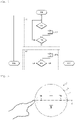
- the detection method starts at step E10 and begins with a first detection phase P1.
- the processing component 12 tries to detect a first occultation of a first microphone (step E11). As long as the first occultation is not detected, the detection method remains at step E11.
- the processing component 12 When the processing component 12 has detected the first occultation of the first microphone, the processing component 12 starts a first timer (or “stopwatch”) which expires after a first predefined duration (step E12).
- the first predefined duration corresponds to the maximum duration of the first occultation of the first microphone which may correspond to a voluntary command slip.
- the first predefined duration is for example equal to ls or 0.5s.
- the processing component 12 detects the end of the first occultation, that is to say a release of the press, and verifies whether the end of the first occultation has taken place before the expiration of the first timer, i.e. that is to say if a first duration of the first occultation is less than the first predefined duration (step E13).
- the detection method therefore comprises a second phase of detection P2 which makes it possible to categorize the command gesture into a command press or a command slip.
- processing component 12 attempts to detect a second occultation of a second microphone distinct from the first microphone (step E14). Simultaneously, at the end of the first occultation, the processing component 12 starts a second timer which expires after a second predefined duration (step E15).
- the second predefined duration corresponds to the maximum duration desired for the finger to pass from one microphone to another during the sliding.
- the second predefined duration is for example equal to 0.5s or to 0.25s.
- the second predefined duration is longer when the microphones 10 are further apart, and lower when the microphones 10 are less spaced.
- the processing component 12 detects that the first muting and the second muting (or the first muting only) constitute two separate command supports (or one command support only) - step E16.
- the processing component 12 detects a slippage of control carried out on the box 2 by the user between the first microphone and the second microphone (step E17).
- the processing component 12 possibly continues the detection if the connected speaker 1 incorporates more than two microphones 10. In this case, the detection of step E11 will be directly validated, because the second occultation of the second microphone has already been detected at step E14.
- processing component 12 If the processing component 12 has detected one or more command presses on virtual buttons, then the processing component 12 implements predetermined actions corresponding to said virtual button or buttons (as above).
- the processing component 12 compares the command slippage with at least one predefined slippage from a predefined list (stored for example in the memory connected to the processing component 12), determines a particular predefined slip to which the control slip corresponds, and controls the connected speaker 1 so that the latter performs at least one predetermined action associated with the particular predefined slip.
- a predefined list stored for example in the memory connected to the processing component 12
- each predefined shift of the predefined list corresponds to a succession of predefined occultations of microphones 10 arranged successively.
- the muting of a first microphone is followed by the muting of a second microphone adjacent to the first microphone.
- Shifts between microphones 10 which are not arranged successively are therefore not allowed, ie they do not correspond to predefined shifts of the predefined list.
- the predefined glides are linear glides.
- a connected speaker 1 comprises two microphones 10a, 10b (and therefore two holes) forming two virtual buttons on the upper face 5 of the box 2.
- each microphone 10 we assimilate each microphone 10 to the associated hole 7 - but of course, in reality, only the hole 7 is visible on the housing 2, the microphone 10 being positioned inside the housing 2.
- the processing component 12 will detect successive occultations of the microphones 10a then 10b (sliding to the right), or of the microphones 10b then 10a (sliding to the left) , all within a reduced time interval (for example less than 1 second).
- a connected speaker 1 according to a second embodiment comprises three microphones 10a, 10b, 10c aligned along the X axis.
- the predetermined action controlled by the control slip may be a step-response action, and in particular a step-response action.
- “Progressive response action” means an action whose response level varies according to the control slip (length, duration of occultation of certain microphones, duration of the slip, etc.) and/or the number of ordered.
- a preset slip in the first direction may be associated with an increase in a response level of the soft-response action, while a preset slip in the second direction may be associated with a reduction in the response level of the progressive response action.
- the progressive response action is for example the adjustment of the sound reproduction volume of the connected speaker 1.
- the list of predefined slides can include several predefined slides in the same direction but of different lengths.
- the length of a preset slide is equal to the number of microphones 10 occulted in the succession of occultations forming the predefined shift.
- the level of response of the step-response action may depend on the length of said predefined slip.
- a control slip which would begin with a muting of the microphone 10a and would end with a muting of the microphone 10b would command a slight increase in volume
- a control slip which would begin with a muting of the microphone 10a and would end with a muting of the microphone 10c would command a strong increase in volume
- a control slip increases or decreases the volume by a maximum of 20%.
- a variation in the level of response of the progressive response action is greater if the predefined glide is followed by a maintained occultation of a microphone at the end of the predefined glide.
- the variation of the level of response can also depend on the duration of the occultation maintained.
- the increase or decrease in volume could be 10% - or even 0% - in the case of a simple control slip, but be equal to 20% per second for the duration of a muting held at the end of the control slip.
- control slips (and therefore the predefined slips) are then circular slips.
- the connected speaker 1 To be able to detect the direction of movement, the connected speaker 1 must include at least three microphones 10 positioned at the periphery. If the connected speaker 1 includes three microphones 10, these are arranged in a triangle.
- a small number of microphones 10 leads to coarse granularity in the response to the user's gestures, and it is therefore preferable, in order to detect circular slips, to provide the connected speaker 1 with a greater number of microphones 10 located in periphery, for example of six or eight microphones 10.
- the connected speaker 1 could potentially include both microphones 10 positioned at the periphery, and a central microphone. It is then possible to detect both linear slips along an axis, and circular slips on the periphery.
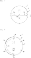
- a connected speaker 1 comprises six microphones 10a, 10b, 10c, 10d, 10e, 10f arranged in a circular manner and forming a ring of microphones on the periphery of the upper face 5 of the housing 2 of the speaker connected 1.
- the predefined slides are therefore circular slides.
- the particular predetermined action is again the adjustment of the sound reproduction volume: a clockwise slide commands an increase in volume, while a counter-clockwise slide commands a reduction in volume.
- control slips in a first direction, that is to say according to a clockwise rotation (such as the control slip 14), or control in a second direction, that is to say according to a counter-clockwise rotation.
- the predefined initial microphone is for example microphone 10a and the predefined final microphone is microphone 10d for the control slide 14 clockwise in the left part of the ring of microphones (volume increase).
- the predefined initial microphone is, for example, microphone 10d and the predefined final microphone is microphone 10a for the clockwise control slide in the right part of the microphone ring (volume increase).
- the initial predefined microphone is for example the microphone 10d and the final microphone predefined the microphone 10a for the control slip according to the anti-clockwise direction in the left part of the crown of microphones (volume reduction).
- the predefined initial microphone is, for example, microphone 10a and the predefined final microphone is microphone 10d for the control sliding in the counter-clockwise direction in the right part of the ring of microphones (volume reduction).
- the other control shifts (for example from the microphone 10c to the microphone 10e) are then not admissible (at least to adjust the volume).
- a connected speaker 1 again comprises six microphones 10a, 10b, 10c, 10d, 10e, 10f arranged in a circular manner. This time there is no microphone in the central Y axis.
- the predefined initial microphone is for example the microphone 10a and the predefined final microphone the microphone 10c for the control slide 15 clockwise in the left part of the ring of microphones.
- the initial predefined microphone is for example the microphone 10d and the final microphone predefined the microphone 10f for the control sliding according to the clockwise direction in the right part of the ring of microphones.
- the configuration of the figure 7 makes it possible to obtain a number of control steps (four steps) greater than the configuration of the figure 8 (three steps) for a half turn, and to make a finer adjustment in the case where the predetermined action associated with the control slip is a step response action (as for volume adjustment).
- the starting point and the ending point of the control slides can also be indifferent, the important thing then being only the arc of the rotation carried out by the user.
- control slides can be limited, for example to half a turn.
- these last two lists will be considered as circular lists. To allow shifts of more than one turn to be taken into account, we will also accept that these last two lists be repeated (as many times as turns are accepted during a command slip).
- the connected speaker 1 comprises a sensory transmitter arranged to provide the user with sensory feedback, representative of the control slippage and/or of a response level of the predetermined action which is controlled following the control slip detection.
- the sensory transmitter is for example a sound transmitter, which here comprises the loudspeaker 6 and the transmission means of the connected enclosure 1.
- the sensory feedback is therefore sound feedback.
- the sound transmitter can for example emit a return sound signal when the response level of the predetermined action crosses (by increasing or decreasing) a predefined level.
- the sound transmitter here emits a first return sound signal, for example a "tick", each time the sound volume crosses a level of 20%.
- the sound transmitter can also emit a return sound signal when the response level of the predetermined action reaches a maximum (or minimum) stop associated with the direction of the control slip, that is to say that the response level reaches a maximum (or minimum) value and does not increase (or decrease) further, even if the user performs further control slides in the same direction.
- the sound transmitter here produces a second feedback sound signal, different from the first feedback sound signal, when the maximum stop (maximum volume) is reached and a third feedback sound signal, different from the first and second feedback beeps, when the minimum stop (minimum volume) is reached.
- the intensity of the return sound signal or signals may be constant (for example in the case of scrolling through radio stations), or modulated in intensity (for example in the case of adjustment of the volume of sound reproduction).
- the sensory transmitter can also be a light transmitter which includes light indicators.
- the luminous indicators comprise for example light-emitting diodes (LEDs).
- the light emitter also comprises components for driving the light indicators (driver).
- the visual feedback may consist of the lighting of one or more light indicators, the intensity and/or color of which may vary.
- the connected speaker 1 controls these light indicators according to the control slip and/or the response level of the predetermined action.
- the connected speaker can for example turn on the light indicators, or else vary their intensity or their color when the level of response of the predetermined action commanded is passed through.
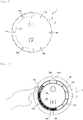
- the connected speaker 1 comprises a plurality of light sources each comprising one or more LEDs.
- Each light source has the shape of a light segment 20 forming an angular sector of a ring of light segments 20.
- the ring of light segments 20 is located inside the ring of microphones 10.
- Some of the light segments 20 are associated with microphones 10 with which they are aligned radially: the light segment 20a is associated with the microphone 10a, the light segment 20b is associated with microphone 10b, light segment 20c is associated with microphone 10c, etc.
- the light emitter emits a return light signal which depends in real time on the path on the box 2 of the user's finger when the control is slid.
- the light segments 20 in front of which the user's finger passed during the control slip remain lit, while the light segment 20c associated with the microphone 10c, where the user's finger is located, flashes.
- the sensory transmitter could produce a feedback sensory signal different from those described here, for example a vibration signal.
- This vibratory signal could for example be produced by means of a dedicated device (device of the vibrator type), or be produced, outside the audible spectrum (infrasound), by means of a loudspeaker (6) of the device.
- the predetermined actions commanded by the command slides may differ from those described here.
- the predetermined actions could for example consist of scrolling through radio stations, advancing or rewinding the playback of audio content, etc.
- the invention can be implemented in any electronic equipment comprising microphones and at least one loudspeaker: voice assistant, decoder box, tablet, smartphone, etc.
Landscapes
- Engineering & Computer Science (AREA)
- Theoretical Computer Science (AREA)
- General Engineering & Computer Science (AREA)
- Physics & Mathematics (AREA)
- Human Computer Interaction (AREA)
- General Physics & Mathematics (AREA)
- Health & Medical Sciences (AREA)
- General Health & Medical Sciences (AREA)
- Acoustics & Sound (AREA)
- Multimedia (AREA)
- Audiology, Speech & Language Pathology (AREA)
- Signal Processing (AREA)
- Otolaryngology (AREA)
- Circuit For Audible Band Transducer (AREA)
- User Interface Of Digital Computer (AREA)
Applications Claiming Priority (1)
| Application Number | Priority Date | Filing Date | Title |
|---|---|---|---|
| FR2104552A FR3122510A1 (fr) | 2021-04-30 | 2021-04-30 | Commande par glissement sur des boutons virtuels |
Publications (2)
| Publication Number | Publication Date |
|---|---|
| EP4086751A1 true EP4086751A1 (de) | 2022-11-09 |
| EP4086751B1 EP4086751B1 (de) | 2024-01-31 |
Family
ID=76284003
Family Applications (1)
| Application Number | Title | Priority Date | Filing Date |
|---|---|---|---|
| EP22170136.0A Active EP4086751B1 (de) | 2021-04-30 | 2022-04-26 | Steuerung durch wischen auf virtuellen schaltflächen |
Country Status (3)
| Country | Link |
|---|---|
| US (1) | US12317041B2 (de) |
| EP (1) | EP4086751B1 (de) |
| FR (1) | FR3122510A1 (de) |
Families Citing this family (2)
| Publication number | Priority date | Publication date | Assignee | Title |
|---|---|---|---|---|
| US12443317B2 (en) * | 2022-12-07 | 2025-10-14 | Google Llc | Assistant control via detecting tactile modulation of ultrasonic signal |
| CN119905094B (zh) * | 2024-12-24 | 2025-11-04 | 海信视像科技股份有限公司 | 电视设备及会话处理方法 |
Citations (3)
| Publication number | Priority date | Publication date | Assignee | Title |
|---|---|---|---|---|
| EP2393305A2 (de) * | 2010-06-01 | 2011-12-07 | Sony Corporation | Vorrichtung zur Tonsignalverarbeitung, Mikrophonvorrichtung, Tonsignalverarbeitungsverfahren und Programm |
| EP3149966A1 (de) * | 2014-05-30 | 2017-04-05 | Sonova AG | Verfahren zur steuerung eines hörgeräts durch berührungsgesten, über berührungsgesten steuerbares hörgerät und verfahren zur passung eines über berührungsgesten steuerbaren hörgeräts |
| US10147441B1 (en) * | 2013-12-19 | 2018-12-04 | Amazon Technologies, Inc. | Voice controlled system |
Family Cites Families (2)
| Publication number | Priority date | Publication date | Assignee | Title |
|---|---|---|---|---|
| KR20140014548A (ko) * | 2012-07-24 | 2014-02-06 | 삼성전자주식회사 | 전자 장치, 그 제어 방법, 및 컴퓨터 판독가능 기록매체 |
| US9569006B2 (en) * | 2014-04-10 | 2017-02-14 | Mediatek Inc. | Ultrasound-based methods for touchless gesture recognition, and apparatuses using the same |
-
2021
- 2021-04-30 FR FR2104552A patent/FR3122510A1/fr not_active Ceased
-
2022
- 2022-04-26 EP EP22170136.0A patent/EP4086751B1/de active Active
- 2022-04-28 US US17/732,284 patent/US12317041B2/en active Active
Patent Citations (3)
| Publication number | Priority date | Publication date | Assignee | Title |
|---|---|---|---|---|
| EP2393305A2 (de) * | 2010-06-01 | 2011-12-07 | Sony Corporation | Vorrichtung zur Tonsignalverarbeitung, Mikrophonvorrichtung, Tonsignalverarbeitungsverfahren und Programm |
| US10147441B1 (en) * | 2013-12-19 | 2018-12-04 | Amazon Technologies, Inc. | Voice controlled system |
| EP3149966A1 (de) * | 2014-05-30 | 2017-04-05 | Sonova AG | Verfahren zur steuerung eines hörgeräts durch berührungsgesten, über berührungsgesten steuerbares hörgerät und verfahren zur passung eines über berührungsgesten steuerbaren hörgeräts |
Also Published As
| Publication number | Publication date |
|---|---|
| FR3122510A1 (fr) | 2022-11-04 |
| US20220353611A1 (en) | 2022-11-03 |
| US12317041B2 (en) | 2025-05-27 |
| EP4086751B1 (de) | 2024-01-31 |
Similar Documents
| Publication | Publication Date | Title |
|---|---|---|
| EP4086751B1 (de) | Steuerung durch wischen auf virtuellen schaltflächen | |
| EP2530673B1 (de) | Audiogerät mit Rauschunterdrückung in einem Sprachsignal unter Verwendung von einem Filter mit fraktionaler Verzögerung | |
| JP6129343B2 (ja) | 録音装置、及び録音装置の制御方法 | |
| EP2615850A1 (de) | Audioaufzeichnungsvorrichtung | |
| KR101520799B1 (ko) | 개인의 청력 특성에 최적화된 음원의 출력을 가능하게 하는 이어폰 장치 | |
| EP3852390B1 (de) | Virtuelle taste, die ein tonsignal benutzt | |
| CA3123970A1 (fr) | Mesure temporelle a haute precision d'evenements vibro-acoustiques en synchronisation avec un signal sonore sur dispositif a ecran tactile | |
| EP3563372A1 (de) | Aufmerksammachen von benutzern auf ereignisse | |
| CN105430563B (zh) | 多频带闪避器 | |
| EP3149968B1 (de) | Verfahren zur unterstützung der verfolgung einer konversation für hörbehinderte | |
| FR3034887B1 (fr) | Dispositif et procede de commande gestuelle en temps reel de signal audio | |
| GB2526980A (en) | Sensor input recognition | |
| FR2635680A1 (fr) | Prothese auditive | |
| EP3591635B1 (de) | Optimierung der steuerung einer oder mehrerer vorrichtungen | |
| US12542147B2 (en) | Mapping sound sources in a user interface | |
| CN113891212A (zh) | 耳机、耳机运行控制方法及计算机可读存储介质 | |
| US20250048041A1 (en) | Processing audio signals from unknown entities | |
| EP2206236A1 (de) | Audio- oder audio/video-abspielgerät mit mitteln zur erfassung eines externen audiosignals | |
| FR2921747A1 (fr) | Procede de traitement d'un signal audio dans un dispositif portable | |
| FR3095070A1 (fr) | Système d’émission d’un effet sonore | |
| FR3097362A1 (fr) | Système vibratoire sensoriel | |
| EP2907021A1 (de) | Verfahren und modul zur steuerung von anlagen mit schallimpuls | |
| FR2921746A1 (fr) | Baladeur audio ou audio-video comprenant des moyens de capture d'un signal audio externe | |
| WO2014053731A1 (fr) | Dispositif de commande d'un systeme informatique et/ou electronique |
Legal Events
| Date | Code | Title | Description |
|---|---|---|---|
| PUAI | Public reference made under article 153(3) epc to a published international application that has entered the european phase |
Free format text: ORIGINAL CODE: 0009012 |
|
| STAA | Information on the status of an ep patent application or granted ep patent |
Free format text: STATUS: REQUEST FOR EXAMINATION WAS MADE |
|
| STAA | Information on the status of an ep patent application or granted ep patent |
Free format text: STATUS: EXAMINATION IS IN PROGRESS |
|
| 17P | Request for examination filed |
Effective date: 20220426 |
|
| AK | Designated contracting states |
Kind code of ref document: A1 Designated state(s): AL AT BE BG CH CY CZ DE DK EE ES FI FR GB GR HR HU IE IS IT LI LT LU LV MC MK MT NL NO PL PT RO RS SE SI SK SM TR |
|
| 17Q | First examination report despatched |
Effective date: 20221019 |
|
| RBV | Designated contracting states (corrected) |
Designated state(s): AL AT BE BG CH CY CZ DE DK EE ES FI FR GB GR HR HU IE IS IT LI LT LU LV MC MK MT NL NO PL PT RO RS SE SI SK SM TR |
|
| GRAP | Despatch of communication of intention to grant a patent |
Free format text: ORIGINAL CODE: EPIDOSNIGR1 |
|
| STAA | Information on the status of an ep patent application or granted ep patent |
Free format text: STATUS: GRANT OF PATENT IS INTENDED |
|
| INTG | Intention to grant announced |
Effective date: 20230831 |
|
| GRAS | Grant fee paid |
Free format text: ORIGINAL CODE: EPIDOSNIGR3 |
|
| RAP3 | Party data changed (applicant data changed or rights of an application transferred) |
Owner name: SAGEMCOM BROADBAND SAS |
|
| GRAA | (expected) grant |
Free format text: ORIGINAL CODE: 0009210 |
|
| STAA | Information on the status of an ep patent application or granted ep patent |
Free format text: STATUS: THE PATENT HAS BEEN GRANTED |
|
| AK | Designated contracting states |
Kind code of ref document: B1 Designated state(s): AL AT BE BG CH CY CZ DE DK EE ES FI FR GB GR HR HU IE IS IT LI LT LU LV MC MK MT NL NO PL PT RO RS SE SI SK SM TR |
|
| REG | Reference to a national code |
Ref country code: GB Ref legal event code: FG4D Free format text: NOT ENGLISH Ref country code: CH Ref legal event code: EP |
|
| REG | Reference to a national code |
Ref country code: DE Ref legal event code: R096 Ref document number: 602022001743 Country of ref document: DE |
|
| REG | Reference to a national code |
Ref country code: IE Ref legal event code: FG4D Free format text: LANGUAGE OF EP DOCUMENT: FRENCH |
|
| REG | Reference to a national code |
Ref country code: LT Ref legal event code: MG9D |
|
| REG | Reference to a national code |
Ref country code: NL Ref legal event code: MP Effective date: 20240131 |
|
| PG25 | Lapsed in a contracting state [announced via postgrant information from national office to epo] |
Ref country code: IS Free format text: LAPSE BECAUSE OF FAILURE TO SUBMIT A TRANSLATION OF THE DESCRIPTION OR TO PAY THE FEE WITHIN THE PRESCRIBED TIME-LIMIT Effective date: 20240531 |
|
| PG25 | Lapsed in a contracting state [announced via postgrant information from national office to epo] |
Ref country code: LT Free format text: LAPSE BECAUSE OF FAILURE TO SUBMIT A TRANSLATION OF THE DESCRIPTION OR TO PAY THE FEE WITHIN THE PRESCRIBED TIME-LIMIT Effective date: 20240131 |
|
| PG25 | Lapsed in a contracting state [announced via postgrant information from national office to epo] |
Ref country code: GR Free format text: LAPSE BECAUSE OF FAILURE TO SUBMIT A TRANSLATION OF THE DESCRIPTION OR TO PAY THE FEE WITHIN THE PRESCRIBED TIME-LIMIT Effective date: 20240501 |
|
| REG | Reference to a national code |
Ref country code: AT Ref legal event code: MK05 Ref document number: 1654319 Country of ref document: AT Kind code of ref document: T Effective date: 20240131 |
|
| PG25 | Lapsed in a contracting state [announced via postgrant information from national office to epo] |
Ref country code: RS Free format text: LAPSE BECAUSE OF FAILURE TO SUBMIT A TRANSLATION OF THE DESCRIPTION OR TO PAY THE FEE WITHIN THE PRESCRIBED TIME-LIMIT Effective date: 20240430 Ref country code: HR Free format text: LAPSE BECAUSE OF FAILURE TO SUBMIT A TRANSLATION OF THE DESCRIPTION OR TO PAY THE FEE WITHIN THE PRESCRIBED TIME-LIMIT Effective date: 20240131 Ref country code: NL Free format text: LAPSE BECAUSE OF FAILURE TO SUBMIT A TRANSLATION OF THE DESCRIPTION OR TO PAY THE FEE WITHIN THE PRESCRIBED TIME-LIMIT Effective date: 20240131 |
|
| PG25 | Lapsed in a contracting state [announced via postgrant information from national office to epo] |
Ref country code: ES Free format text: LAPSE BECAUSE OF FAILURE TO SUBMIT A TRANSLATION OF THE DESCRIPTION OR TO PAY THE FEE WITHIN THE PRESCRIBED TIME-LIMIT Effective date: 20240131 |
|
| PG25 | Lapsed in a contracting state [announced via postgrant information from national office to epo] |
Ref country code: AT Free format text: LAPSE BECAUSE OF FAILURE TO SUBMIT A TRANSLATION OF THE DESCRIPTION OR TO PAY THE FEE WITHIN THE PRESCRIBED TIME-LIMIT Effective date: 20240131 |
|
| PG25 | Lapsed in a contracting state [announced via postgrant information from national office to epo] |
Ref country code: RS Free format text: LAPSE BECAUSE OF FAILURE TO SUBMIT A TRANSLATION OF THE DESCRIPTION OR TO PAY THE FEE WITHIN THE PRESCRIBED TIME-LIMIT Effective date: 20240430 Ref country code: NO Free format text: LAPSE BECAUSE OF FAILURE TO SUBMIT A TRANSLATION OF THE DESCRIPTION OR TO PAY THE FEE WITHIN THE PRESCRIBED TIME-LIMIT Effective date: 20240430 Ref country code: NL Free format text: LAPSE BECAUSE OF FAILURE TO SUBMIT A TRANSLATION OF THE DESCRIPTION OR TO PAY THE FEE WITHIN THE PRESCRIBED TIME-LIMIT Effective date: 20240131 Ref country code: LT Free format text: LAPSE BECAUSE OF FAILURE TO SUBMIT A TRANSLATION OF THE DESCRIPTION OR TO PAY THE FEE WITHIN THE PRESCRIBED TIME-LIMIT Effective date: 20240131 Ref country code: IS Free format text: LAPSE BECAUSE OF FAILURE TO SUBMIT A TRANSLATION OF THE DESCRIPTION OR TO PAY THE FEE WITHIN THE PRESCRIBED TIME-LIMIT Effective date: 20240531 Ref country code: HR Free format text: LAPSE BECAUSE OF FAILURE TO SUBMIT A TRANSLATION OF THE DESCRIPTION OR TO PAY THE FEE WITHIN THE PRESCRIBED TIME-LIMIT Effective date: 20240131 Ref country code: GR Free format text: LAPSE BECAUSE OF FAILURE TO SUBMIT A TRANSLATION OF THE DESCRIPTION OR TO PAY THE FEE WITHIN THE PRESCRIBED TIME-LIMIT Effective date: 20240501 Ref country code: FI Free format text: LAPSE BECAUSE OF FAILURE TO SUBMIT A TRANSLATION OF THE DESCRIPTION OR TO PAY THE FEE WITHIN THE PRESCRIBED TIME-LIMIT Effective date: 20240131 Ref country code: ES Free format text: LAPSE BECAUSE OF FAILURE TO SUBMIT A TRANSLATION OF THE DESCRIPTION OR TO PAY THE FEE WITHIN THE PRESCRIBED TIME-LIMIT Effective date: 20240131 Ref country code: BG Free format text: LAPSE BECAUSE OF FAILURE TO SUBMIT A TRANSLATION OF THE DESCRIPTION OR TO PAY THE FEE WITHIN THE PRESCRIBED TIME-LIMIT Effective date: 20240131 Ref country code: AT Free format text: LAPSE BECAUSE OF FAILURE TO SUBMIT A TRANSLATION OF THE DESCRIPTION OR TO PAY THE FEE WITHIN THE PRESCRIBED TIME-LIMIT Effective date: 20240131 |
|
| PG25 | Lapsed in a contracting state [announced via postgrant information from national office to epo] |
Ref country code: PL Free format text: LAPSE BECAUSE OF FAILURE TO SUBMIT A TRANSLATION OF THE DESCRIPTION OR TO PAY THE FEE WITHIN THE PRESCRIBED TIME-LIMIT Effective date: 20240131 Ref country code: PT Free format text: LAPSE BECAUSE OF FAILURE TO SUBMIT A TRANSLATION OF THE DESCRIPTION OR TO PAY THE FEE WITHIN THE PRESCRIBED TIME-LIMIT Effective date: 20240531 |
|
| PG25 | Lapsed in a contracting state [announced via postgrant information from national office to epo] |
Ref country code: SE Free format text: LAPSE BECAUSE OF FAILURE TO SUBMIT A TRANSLATION OF THE DESCRIPTION OR TO PAY THE FEE WITHIN THE PRESCRIBED TIME-LIMIT Effective date: 20240131 Ref country code: PT Free format text: LAPSE BECAUSE OF FAILURE TO SUBMIT A TRANSLATION OF THE DESCRIPTION OR TO PAY THE FEE WITHIN THE PRESCRIBED TIME-LIMIT Effective date: 20240531 Ref country code: PL Free format text: LAPSE BECAUSE OF FAILURE TO SUBMIT A TRANSLATION OF THE DESCRIPTION OR TO PAY THE FEE WITHIN THE PRESCRIBED TIME-LIMIT Effective date: 20240131 Ref country code: LV Free format text: LAPSE BECAUSE OF FAILURE TO SUBMIT A TRANSLATION OF THE DESCRIPTION OR TO PAY THE FEE WITHIN THE PRESCRIBED TIME-LIMIT Effective date: 20240131 |
|
| PG25 | Lapsed in a contracting state [announced via postgrant information from national office to epo] |
Ref country code: DK Free format text: LAPSE BECAUSE OF FAILURE TO SUBMIT A TRANSLATION OF THE DESCRIPTION OR TO PAY THE FEE WITHIN THE PRESCRIBED TIME-LIMIT Effective date: 20240131 |
|
| PG25 | Lapsed in a contracting state [announced via postgrant information from national office to epo] |
Ref country code: SM Free format text: LAPSE BECAUSE OF FAILURE TO SUBMIT A TRANSLATION OF THE DESCRIPTION OR TO PAY THE FEE WITHIN THE PRESCRIBED TIME-LIMIT Effective date: 20240131 |
|
| PG25 | Lapsed in a contracting state [announced via postgrant information from national office to epo] |
Ref country code: EE Free format text: LAPSE BECAUSE OF FAILURE TO SUBMIT A TRANSLATION OF THE DESCRIPTION OR TO PAY THE FEE WITHIN THE PRESCRIBED TIME-LIMIT Effective date: 20240131 Ref country code: CZ Free format text: LAPSE BECAUSE OF FAILURE TO SUBMIT A TRANSLATION OF THE DESCRIPTION OR TO PAY THE FEE WITHIN THE PRESCRIBED TIME-LIMIT Effective date: 20240131 |
|
| PG25 | Lapsed in a contracting state [announced via postgrant information from national office to epo] |
Ref country code: SK Free format text: LAPSE BECAUSE OF FAILURE TO SUBMIT A TRANSLATION OF THE DESCRIPTION OR TO PAY THE FEE WITHIN THE PRESCRIBED TIME-LIMIT Effective date: 20240131 |
|
| PG25 | Lapsed in a contracting state [announced via postgrant information from national office to epo] |
Ref country code: SM Free format text: LAPSE BECAUSE OF FAILURE TO SUBMIT A TRANSLATION OF THE DESCRIPTION OR TO PAY THE FEE WITHIN THE PRESCRIBED TIME-LIMIT Effective date: 20240131 Ref country code: SK Free format text: LAPSE BECAUSE OF FAILURE TO SUBMIT A TRANSLATION OF THE DESCRIPTION OR TO PAY THE FEE WITHIN THE PRESCRIBED TIME-LIMIT Effective date: 20240131 Ref country code: RO Free format text: LAPSE BECAUSE OF FAILURE TO SUBMIT A TRANSLATION OF THE DESCRIPTION OR TO PAY THE FEE WITHIN THE PRESCRIBED TIME-LIMIT Effective date: 20240131 Ref country code: EE Free format text: LAPSE BECAUSE OF FAILURE TO SUBMIT A TRANSLATION OF THE DESCRIPTION OR TO PAY THE FEE WITHIN THE PRESCRIBED TIME-LIMIT Effective date: 20240131 Ref country code: DK Free format text: LAPSE BECAUSE OF FAILURE TO SUBMIT A TRANSLATION OF THE DESCRIPTION OR TO PAY THE FEE WITHIN THE PRESCRIBED TIME-LIMIT Effective date: 20240131 Ref country code: CZ Free format text: LAPSE BECAUSE OF FAILURE TO SUBMIT A TRANSLATION OF THE DESCRIPTION OR TO PAY THE FEE WITHIN THE PRESCRIBED TIME-LIMIT Effective date: 20240131 |
|
| REG | Reference to a national code |
Ref country code: DE Ref legal event code: R097 Ref document number: 602022001743 Country of ref document: DE |
|
| PG25 | Lapsed in a contracting state [announced via postgrant information from national office to epo] |
Ref country code: MC Free format text: LAPSE BECAUSE OF FAILURE TO SUBMIT A TRANSLATION OF THE DESCRIPTION OR TO PAY THE FEE WITHIN THE PRESCRIBED TIME-LIMIT Effective date: 20240131 |
|
| PG25 | Lapsed in a contracting state [announced via postgrant information from national office to epo] |
Ref country code: MC Free format text: LAPSE BECAUSE OF FAILURE TO SUBMIT A TRANSLATION OF THE DESCRIPTION OR TO PAY THE FEE WITHIN THE PRESCRIBED TIME-LIMIT Effective date: 20240131 |
|
| PG25 | Lapsed in a contracting state [announced via postgrant information from national office to epo] |
Ref country code: IT Free format text: LAPSE BECAUSE OF FAILURE TO SUBMIT A TRANSLATION OF THE DESCRIPTION OR TO PAY THE FEE WITHIN THE PRESCRIBED TIME-LIMIT Effective date: 20240131 |
|
| PLBE | No opposition filed within time limit |
Free format text: ORIGINAL CODE: 0009261 |
|
| STAA | Information on the status of an ep patent application or granted ep patent |
Free format text: STATUS: NO OPPOSITION FILED WITHIN TIME LIMIT |
|
| PG25 | Lapsed in a contracting state [announced via postgrant information from national office to epo] |
Ref country code: LU Free format text: LAPSE BECAUSE OF NON-PAYMENT OF DUE FEES Effective date: 20240426 |
|
| REG | Reference to a national code |
Ref country code: BE Ref legal event code: MM Effective date: 20240430 |
|
| PG25 | Lapsed in a contracting state [announced via postgrant information from national office to epo] |
Ref country code: LU Free format text: LAPSE BECAUSE OF NON-PAYMENT OF DUE FEES Effective date: 20240426 Ref country code: IT Free format text: LAPSE BECAUSE OF FAILURE TO SUBMIT A TRANSLATION OF THE DESCRIPTION OR TO PAY THE FEE WITHIN THE PRESCRIBED TIME-LIMIT Effective date: 20240131 |
|
| 26N | No opposition filed |
Effective date: 20241101 |
|
| PG25 | Lapsed in a contracting state [announced via postgrant information from national office to epo] |
Ref country code: BE Free format text: LAPSE BECAUSE OF NON-PAYMENT OF DUE FEES Effective date: 20240430 |
|
| PG25 | Lapsed in a contracting state [announced via postgrant information from national office to epo] |
Ref country code: BE Free format text: LAPSE BECAUSE OF NON-PAYMENT OF DUE FEES Effective date: 20240430 |
|
| PG25 | Lapsed in a contracting state [announced via postgrant information from national office to epo] |
Ref country code: IE Free format text: LAPSE BECAUSE OF NON-PAYMENT OF DUE FEES Effective date: 20240426 |
|
| PG25 | Lapsed in a contracting state [announced via postgrant information from national office to epo] |
Ref country code: SI Free format text: LAPSE BECAUSE OF FAILURE TO SUBMIT A TRANSLATION OF THE DESCRIPTION OR TO PAY THE FEE WITHIN THE PRESCRIBED TIME-LIMIT Effective date: 20240131 |
|
| PGFP | Annual fee paid to national office [announced via postgrant information from national office to epo] |
Ref country code: DE Payment date: 20250319 Year of fee payment: 4 |
|
| PG25 | Lapsed in a contracting state [announced via postgrant information from national office to epo] |
Ref country code: CY Free format text: LAPSE BECAUSE OF FAILURE TO SUBMIT A TRANSLATION OF THE DESCRIPTION OR TO PAY THE FEE WITHIN THE PRESCRIBED TIME-LIMIT; INVALID AB INITIO Effective date: 20220426 |
|
| PG25 | Lapsed in a contracting state [announced via postgrant information from national office to epo] |
Ref country code: HU Free format text: LAPSE BECAUSE OF FAILURE TO SUBMIT A TRANSLATION OF THE DESCRIPTION OR TO PAY THE FEE WITHIN THE PRESCRIBED TIME-LIMIT; INVALID AB INITIO Effective date: 20220426 |
|
| REG | Reference to a national code |
Ref country code: CH Ref legal event code: H13 Free format text: ST27 STATUS EVENT CODE: U-0-0-H10-H13 (AS PROVIDED BY THE NATIONAL OFFICE) Effective date: 20251125 |
|
| PG25 | Lapsed in a contracting state [announced via postgrant information from national office to epo] |
Ref country code: CH Free format text: LAPSE BECAUSE OF NON-PAYMENT OF DUE FEES Effective date: 20250430 |
|
| PGFP | Annual fee paid to national office [announced via postgrant information from national office to epo] |
Ref country code: GB Payment date: 20260319 Year of fee payment: 5 |
|
| PGFP | Annual fee paid to national office [announced via postgrant information from national office to epo] |
Ref country code: FR Payment date: 20260320 Year of fee payment: 5 |