EP4086607B1 - Vorrichtung und system zur bündelung von probenpartikeln - Google Patents
Vorrichtung und system zur bündelung von probenpartikeln Download PDFInfo
- Publication number
- EP4086607B1 EP4086607B1 EP21172793.8A EP21172793A EP4086607B1 EP 4086607 B1 EP4086607 B1 EP 4086607B1 EP 21172793 A EP21172793 A EP 21172793A EP 4086607 B1 EP4086607 B1 EP 4086607B1
- Authority
- EP
- European Patent Office
- Prior art keywords
- wave
- fluid channel
- application region
- acoustic
- fluid
- Prior art date
- Legal status (The legal status is an assumption and is not a legal conclusion. Google has not performed a legal analysis and makes no representation as to the accuracy of the status listed.)
- Active
Links
Images

Classifications
-
- G—PHYSICS
- G01—MEASURING; TESTING
- G01N—INVESTIGATING OR ANALYSING MATERIALS BY DETERMINING THEIR CHEMICAL OR PHYSICAL PROPERTIES
- G01N15/00—Investigating characteristics of particles; Investigating permeability, pore-volume or surface-area of porous materials
- G01N15/10—Investigating individual particles
- G01N15/14—Optical investigation techniques, e.g. flow cytometry
- G01N15/1456—Optical investigation techniques, e.g. flow cytometry without spatial resolution of the texture or inner structure of the particle, e.g. processing of pulse signals
- G01N15/1459—Optical investigation techniques, e.g. flow cytometry without spatial resolution of the texture or inner structure of the particle, e.g. processing of pulse signals the analysis being performed on a sample stream
-
- G—PHYSICS
- G01—MEASURING; TESTING
- G01N—INVESTIGATING OR ANALYSING MATERIALS BY DETERMINING THEIR CHEMICAL OR PHYSICAL PROPERTIES
- G01N15/00—Investigating characteristics of particles; Investigating permeability, pore-volume or surface-area of porous materials
- G01N15/10—Investigating individual particles
- G01N15/14—Optical investigation techniques, e.g. flow cytometry
- G01N15/1425—Optical investigation techniques, e.g. flow cytometry using an analyser being characterised by its control arrangement
-
- G—PHYSICS
- G01—MEASURING; TESTING
- G01N—INVESTIGATING OR ANALYSING MATERIALS BY DETERMINING THEIR CHEMICAL OR PHYSICAL PROPERTIES
- G01N1/00—Sampling; Preparing specimens for investigation
- G01N1/28—Preparing specimens for investigation including physical details of (bio-)chemical methods covered elsewhere, e.g. G01N33/50, C12Q
- G01N1/40—Concentrating samples
- G01N1/4077—Concentrating samples by other techniques involving separation of suspended solids
-
- G—PHYSICS
- G01—MEASURING; TESTING
- G01N—INVESTIGATING OR ANALYSING MATERIALS BY DETERMINING THEIR CHEMICAL OR PHYSICAL PROPERTIES
- G01N15/00—Investigating characteristics of particles; Investigating permeability, pore-volume or surface-area of porous materials
- G01N15/01—Investigating characteristics of particles; Investigating permeability, pore-volume or surface-area of porous materials specially adapted for biological cells, e.g. blood cells
-
- G—PHYSICS
- G01—MEASURING; TESTING
- G01N—INVESTIGATING OR ANALYSING MATERIALS BY DETERMINING THEIR CHEMICAL OR PHYSICAL PROPERTIES
- G01N1/00—Sampling; Preparing specimens for investigation
- G01N1/28—Preparing specimens for investigation including physical details of (bio-)chemical methods covered elsewhere, e.g. G01N33/50, C12Q
- G01N1/40—Concentrating samples
- G01N1/4077—Concentrating samples by other techniques involving separation of suspended solids
- G01N2001/4094—Concentrating samples by other techniques involving separation of suspended solids using ultrasound
-
- G—PHYSICS
- G01—MEASURING; TESTING
- G01N—INVESTIGATING OR ANALYSING MATERIALS BY DETERMINING THEIR CHEMICAL OR PHYSICAL PROPERTIES
- G01N15/00—Investigating characteristics of particles; Investigating permeability, pore-volume or surface-area of porous materials
- G01N15/10—Investigating individual particles
- G01N2015/1006—Investigating individual particles for cytology
-
- G—PHYSICS
- G01—MEASURING; TESTING
- G01N—INVESTIGATING OR ANALYSING MATERIALS BY DETERMINING THEIR CHEMICAL OR PHYSICAL PROPERTIES
- G01N15/00—Investigating characteristics of particles; Investigating permeability, pore-volume or surface-area of porous materials
- G01N15/10—Investigating individual particles
- G01N15/14—Optical investigation techniques, e.g. flow cytometry
- G01N15/1404—Handling flow, e.g. hydrodynamic focusing
- G01N2015/142—Acoustic or ultrasonic focussing
Definitions
- the invention relates to a device and a system for bunching of sample particles.
- Serial femtosecond crystallography known from the prior art uses intense and short pulses of X-rays from a free-electron laser to record many snapshot diffraction patterns of particles, in particular protein crystals, that flow across the X-ray beam generated by an X-ray source.
- Serial femtosecond crystallography was developed primarily to overcome the issue of radiation damage that may occur in conventional particle crystallography using X-ray tubes or synchrotron radiation, for example.
- the exposure to the X-ray beam modifies the structure under investigation, requiring a relatively large structure size of the particles, in particular large crystals, which are often difficult to grow, and cryogenic temperatures, which may also modify the structure from the physiologically relevant one.
- the short pulses of the X-ray free-electron laser (XFELs) are detected and the resulting structural information gained before destruction of the particle under X-ray exposure takes place, allowing much greater exposures, and hence much smaller particles which do not need to be cryogenically cooled.
- the particle is completely vaporized after the X-ray exposure, so measurements must be carried out repeatedly, each time with a fresh particle.
- One way to accomplish that is to flow a slurry comprising many distributed particles in a liquid jet across the X-ray beam.
- the duty cycle of the X-ray pulses is low when comparing the duration of pulses to the duration between pulses.
- the object is solved by a device according to claim 1.
- the device comprises a body, being formed as a chip, from a body material being a chip material, a fluid channel extending through the body, an acoustic wave guide embedded in the body, and an acoustic wave condenser embedded in the body.
- the fluid channel forms a fluid path through the body, such that the fluid channel is configured to guide a flow of a sample fluid, in which sample particles are distributed, through the fluid channel along the fluid path.
- the wave guide is configured to guide an acoustic reference wave, when transmitted via the body to the wave guide, to an application region of the fluid channel.
- the wave condenser at least partly forms the application region of the fluid channel.
- the wave condenser is configured to generate a standing acoustic wave in the application region from the reference wave when the wave guide guides the reference wave into the application region resulting in an acoustic force field in the application region, which pushes sample particles when entering the application region into at least one bunch of sample particles in the application region.
- the device offers the advantage that particles distributed in a fluid and carried by a fluid flow through the fluid channel of the device can be concentrated by means of the device into a bunch within the application area.
- a plurality of particles is arranged in the bunch, such that the concentration of particles within this bunch is significantly higher than the concentration of particles within the fluid upstream of the application area.
- the bunch may be transported downstream with the flow of the fluid to be subsequently examined by means of X-rays.
- the bunch of particles generated in the application area of the fluid channel of the device is examined by means of the X-rays. In this case, the X-rays also penetrate the device.
- the particles are preferably formed by crystals, in particular protein crystals, or cells.
- the X-rays are directed at the application area itself or at an area downstream of the application area rather than at a section of the fluid channel upstream of the application area, and if it is also ensured that the X-rays are directed at the bunch of particles generated by means of the device, then there is a significantly higher probability that the X-rays will encounter at least one of the particles in the bunch.
- the interaction with the particles modifies the X-radiation so that the resulting modified X-radiation is detectable by means of a detector. Based on the measured, modified X-ray radiation, information about the structural configuration of the particles can be obtained.
- the wave condenser may be configured and/or formed to localize the acoustic force field in the application region.
- the acoustic force field may be an acoustic pressure field or may be a result of the acoustic pressure field.
- the standing acoustic wave causes an acoustic force field within the application area, which acts on the particles transported by the fluid into the application area, causing the particles to be compressed and/or concentrated into a bunch within the application area.
- the particles distributed in the sample fluid will move in the presence of an acoustic force field when the acoustic properties of particles and sample fluid are different, which is preferably assumed. Such a difference may relate to an acoustic contrast factor, density of the particles and the fluid, compressibility of the particles and fluid, as well as sound speed of the particles and the fluid.
- the magnitude of the acoustic force of the acoustic force field on particles depends on several factors such as particle size, acoustic energy density, acoustic wave frequency, and acoustic contrast factor.
- the direction of movement of the particles in an acoustic field may depend on the acoustic contrast factor so that particles may move from a region of high to low or low to high pressure, but in either case, a concentration of the particles will take place.
- the high- and low-pressure regions are effectively produced by the acoustic standing wave.
- a primary axial (PA) acoustic radiation force of the standing acoustic wave moves particles in the application region to the nodal plane of the standing acoustic wave. It can be for example used for lining up the particles to the middle of the application region of the fluid channel.
- the wave guide can be designed in very different ways.
- the wave guide may be single-piece or multi-piece.
- the wave guide may also be formed as an integral part of the body of the device.
- the wave guide may be formed by one or more portions of the body of the device.
- the wave guide forms at least two mutually spaced edges at which the acoustic reference wave is at least partially reflected.
- the edges are not necessarily formed by physical structural edges.
- the at least two mutually spaced edges may be disposed within the body of the device such that they guide the acoustic reference wave to the fluid channel application region.
- Each of the edges may be formed by a transition from one material to another material. Additionally or alternatively, each of the edges may be formed by a junction of an acoustic impedance within the body of the device. Each edge may therefore be created by a cavity within the body of the device.
- the wave guide may be configured to cause a higher acoustic intensity to the application region.
- the acoustic reference wave can be generated by normal size transducers instead of small ones to transfer the acoustic power of a large area to small area in microfluidic chip.
- the small (micron) size transducers have challenges in fabrication, soldering, and implementation in microfluidic device for such application
- the power of the small size acoustic transducer may be deliberately concentrated by the wave guide to the application region of the fluid channel instead of attenuating it because of actuating the entire body or device.
- the wave guide and/or the wave condenser may be integrally formed in the body by femtosecond laser induced chemical etching (FLICE) or two-photon polymerization (2PP).
- FLICE femtosecond laser induced chemical etching
- 2PP two-photon polymerization
- the fluid channel downstream from the application region is formed by a further linear wall section of the channel wall.
- This linear wall section may also be circularly cylindrical.
- Each edge may cause a streaming in the application region of the fluid channel.
- the streaming may also refer to as circular streaming or spiral streaming.
- the streaming may be formed by fluid in the application region set into circulatory motion by the edge. As a result, the fluid may circulate in within the application region right next to the edge.
- the streams and/or the circulating fluid may cause (further) force pushing particles entering the application region towards the center of the application region. This further supports the bunching of the particles.
- the body material of the body is based on glass, silicon, metal, diamond, sapphire or plastic.
- the body material is glass, silicon, metal, diamond, sapphire, ceramic or plastic.
- the system comprises a second device.
- the second device is formed by another device according to the first aspect of the invention and/or one of the related preferred embodiments.
- the advantageous explanations, preferred features, technical effects and/or advantages as explained in connection with the first aspect of the device and/or the related preferred embodiments are referred to in an analogous manner for the second device of the system.
- the second device may be configured analogously to the first device.
- the fluid channel of the first device and the fluid channel of the second device are connected in series, such that the fluid channel of the second device is downstream to the fluid channel of the first device.
- the first device and the second device may be formed in an integral manner, so that the two devices are formed as a single device.
- This single-piece device may thus be formed in a first section by the first device and in a further, second section by the second device.
- the second device already explained may be used, which can be coupled in series with the first device.
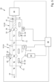
- the device 10 includes a body 14, a fluid channel 16, an acoustic wave guide 18, and an acoustic wave condenser 20.
- the body 14 of the device 10 may also be referred to as the base body 14.
- the body 14 may be formed in one part or in multiple parts.
- the body 14 is made of glass, silicon, metal, diamond, sapphire, ceramic or plastic. Accordingly, the same applies to the body material 34 of the body 14.
- the parts may be formed of different materials, preferably each based on a material from the aforementioned selection of materials.
- the fluid channel 16 of the device 10 extends through the body 14, and it can therefore also be referred to that the fluid channel 16 is embedded in the body 14 of the device 10. It has been found to be particularly advantageous if the fluid channel 16 is integrally formed by the body 14. As schematically shown in Figure 1 , it may preferably be provided that a channel wall of the fluid channel 16 is integrally formed by the body 14 and/or the body material 34 of the body 14.
- the wave guide 18 comprises, for example, two cavities 30 within the body 14.
- the two cavities 30 of the wave guide 18 are spaced apart from each other such that a guiding section 32 is formed between the two cavities 30.
- the guiding section 32 may also be referred to as the guide section 32.
- This guiding section 32 may be formed by the body material 34 of the body 14.
- the two cavities 30 may each be formed as vacuum cavities 30. However, it is also possible that each cavity 30 is filled with a gas, in particular air.
- a step in the acoustic impedance occurs.
- the acoustic reference wave is preferably transmitted to the body 14 by means of the first wave generator 48 of the system 46, the acoustic reference wave is further transmitted by the body material 34 of the body 14 and/or at least partially reflected at the aforementioned cavities 30 due to the step in the acoustic impedance.
- the acoustic reference wave is at least partially held in the guiding section 32 between the cavities 30 and thereby directed into the application region 26 of the fluid channel 16.
- the guiding section 32 of the wave guide 18 is aligned with the application region 26 along a direction perpendicular to the transport direction 44.
- the wave condenser 20 of the device 10 is formed by the body 14 and/or is formed as an integral part of the body 14.
- the wave condenser 20 is formed, for example, by two oppositely disposed concave channel wall sections 36 of a channel wall of the fluid channel 16.
- the channel wall of the fluid channel is preferably integrally formed by the body 14.
- each of the two concave channel wall sections 36 may also be integrally formed through the body 14.
- a maximum distance and/or channel diameter between the two oppositely disposed concave channel wall sections 36 is also referred to as a reference width 42.
- the two oppositely disposed concave channel wall sections 36 expand the channel diameter in the application region 26.
- the reference width 42 is larger than the diameter of the fluid channel 16 in a linear wall section 40 upstream and/or downstream of the application region 26 of the fluid channel 16.
- the wave condenser 20 and/or the associated concave channel wall sections 36 are formed such that the reference width 42 corresponds to a half wavelength of the acoustic reference wave.
- the reference width 42 can deviate from half the wavelength of the acoustic reference wave by a maximum of 10% or a maximum of 5%.
- an edge 38 is preferably formed in at least one transition region from a linear wall section 40 of the channel wall to the at least one concave shaped wall section 36 of the channel wall. As can be seen schematically from Figure 1 , such an edge 38 is formed, for example, in the transition region from the linear wall section 40 of the channel wall located upstream of the application region 26 to each concave shaped wall section 36.
- each edge 38 may cause a spiral or circular motion of the fluid 24 within the application region 26, said motion forcing particles 12 into the center of the application region 26. Said movement thus helps to concentrate particles 12 into the bunch 28 within application region 26.
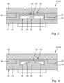
- FIG. 2 A further preferred embodiment of the device 10 is schematically shown in Figure 2 .
- the reference width 42 in the application region 26 is smaller than the average diameter of the fluid channel 16 upstream and/or downstream of the application region 26.
- the reference width 42 is configured such that an acoustic reference wave, for example generated by the first wave generator 48 and transmitted to the body 14 of the device 10, results in a standing acoustic wave within the application region 26.
- the larger or smaller diameter of the fluid channel 16 upstream and/or downstream of the application region 26 may be adapted to prevent a standing acoustic wave from being generated in these regions of the fluid channel 16, even if a portion of the reference acoustic wave enters one of said regions of the fluid channel 16 (downstream and/or upstream of the application region 26).
- the body 14 of the device 10 is formed in multiple parts.
- the body 14 comprises a bottom part 66 and a top part 68 arranged on the bottom part 66.
- the fluid channel 16 is formed, at least partly, between the bottom part 66 and the top part 68.
- the application region 26 of the fluid channel 16 is formed exclusively in a region directly between the bottom part 66 and the top part 68.
- the remaining region of the fluid channel 16 may, for example, be exclusively integrated and/or embedded in the bottom part 66 of the body 14.
- the material of the top part 68 may be different from the material of the bottom part 66.
- the bottom part 66 and the top part 68 are formed of the same material.
- the wave guide 18 is exclusively embedded and/or integrated in the bottom part 66 of the body 14.
- the structural design of the top part 68 may be particularly simple.
- the top part 68 may be formed by a glass plate.
- the bottom part 66 may be formed of glass, silicone, metal, diamond, sapphire, ceramic or plastic.
- the bottom part 66 is formed in one piece.
- the top part 68 may also be formed in one piece.
- the body 14 consists of exactly two parts.
- the wave guide 18 has two cavities 30 which are arranged at a distance from one another and are each rectangular in cross-section.
- Each of the two cavities 30 may be formed as a closed cavity 30.
- each of the two cavities 30 is formed to be open to the surroundings.
- the distance between the two cavities 30 is configured such that no standing acoustic wave can be formed between the two cavities 30.
- the distance between the two cavities 30 is greater than half the wavelength of the acoustic reference wave or greater than the entire wavelength of the acoustic reference wave.
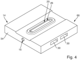
- Figure 3 shows a further preferred embodiment of the device 10.
- This device 10 corresponds at least substantially to the device as shown in Figure 2 .
- the associated advantageous explanations, preferred features, effects and/or advantages as explained in connection with Figure 2 are therefore referred to in an analogous manner for the device 10 of Figure 3 .
- the device 10 of Figure 3 differs from the device 10 of Figure 2 in particular by the geometric shape of the cavities 30.
- the cavities 30 are shaped in cross-section such that the guide section 32 between the cavities 30 is chronically convergent towards the application region 26.
- the cross-section of the cavities 30 may be shaped such that the guide section 32 reduces in size in the direction of the application region 26.
- an at least substantially conical shape for the guiding section 32 can be achieved.
- the conical shape of the guiding section 32 ensures that the intensity of the acoustic reference wave when it enters the application region 26 is particularly high.
- the device 10 may form a part of the system 46, such as is also illustrated in Figure 1 .
- the system 46 preferably includes the pump 52 and the first wave generator 48.
- the first wave generator 48 is directly connected to the body 14 of the device 10 such that a reference acoustic wave generated by the first wave generator 48 is transmitted directly to the body 14 such that the reference acoustic wave propagates within the body material 34 of the body 14.
- the acoustic reference wave reaches the region of the wave guide 18, at least a portion of this acoustic reference wave is directed into the application region 26 by the wave guide 18.
- the pump 52 may be coupled to the fluid channel 16 of the device 10 by means of a connector 70, such that the pump 52 may pump the fluid 24 into the fluid channel 16 in the transport direction 44 via the connector 70.
- the connector 70 may be formed by a hose or a tube, for example. However, it is also possible for the pump 52 to be directly coupled to the fluid channel 16 of the device (not shown in Figure 1 ).
- the system 46 further comprises a control unit 60 configured to control the first wave generator 48.
- the control unit 60 may be configured to control the first wave generator 48 such that the first wave generator 48 generates the acoustic reference wave in a first pattern of alternating on-periods and off-periods.
- a new bunch of particles 12 is generated in the application region 26 of the fluid channel 16 of the device 10.
- the generated bunch 28 of particles 12 is released, captured by the flow of fluid 24, and transported in the transport direction 44.
- the system 46 further comprises a radiation generator 62 and a radiation detector 64.
- the radiation generator 62 is configured to generate radiation.
- the radiation may be, for example, X-rays or infrared radiation.
- the radiation may also be visible light or UV light.
- the radiation generator 62 is configured as an X-ray radiation generator 62 or an infrared radiation generator 62.
- the radiation generator 62 is arranged such that the flow of fluid 24 arrives downstream to an application area 72, and that the radiation generator 62 is arranged such that the application area 72 is exposed to radiation generated by the radiation generator 62.
- the radiation generated by the radiation generator 62 is modified when it impinges on the particles 12 of the bunch 28, thus resulting in modified radiation.
- the radiation detector 64 is preferably arranged such that the radiation detector 64 can detect the modified radiation.
- the radiation generator 62 and the radiation detector 64 may be arranged on opposite sides to the application area 72.
- the application area 72 it is possible for the application area 72 to be arranged outside the fluid channel 16 of the device 10. However, it is also possible that the application area 72 is formed by a portion of the fluid channel 16. For example, the application area 72 may be formed in a section of the fluid channel 16 downstream of the application region 26. Further, it is possible that the application area 72 is disposed in and/or coincides with the application region 26. In this case, it is possible that the particles 12 of a bunch 28 generated in the application region 26 are exposed to the radiation generated by the radiation generator 62, resulting in the modified radiation that can be detected by the radiation detector 64. In this case, the radiation generator 62 and the radiation detector 64 may be arranged on opposite outer sides in a direction perpendicular to the transport direction 44 in alignment with the application region 26.
- FIG. 5 Another preliminary embodiment of the system 46 is shown schematically in Figure 5 .
- the device 10 of the system 46 of Figure 1 forms the first device 50 of the system 46.
- the system 46 of Figure 5 further comprises a second device 54. Both devices 50, 54 may be at least substantially the same.
- the first device 50 and the second device 54 are connected in series such that the fluid channel 16 of the first device 50 is coupled downstream to the fluid channel 16 of the second device 54.
- the fluid channel 16 of the first device 50 is connected to the fluid channel 16 of the second device 54 by a (further) connector. This is shown purely by way of example in Figure 5 .
- first device 50 is directly coupled to the second device 54, a particularly compact design of the system 46 can be achieved.
- a further advantageous embodiment (not shown) is characterized in that the first device 50 and the second device 54 are at least partially integrally formed with each other or are formed by two portions of a common device.
- the flow of the fluid 24 is directed through two application regions 26 arranged one behind the other, namely first through the application region 26 of the first device 50 and then through the application region 26 of the second device 54. Therefore, it can also be referred to that the fluid channel 16 of the first device 50 and the fluid channel 16 of the second device 54 form a common fluid channel of the system 46.
- the particles 12 are concentrated into a bunch 28.
- the fluid 24 carries the bunch 28 of particles 12 into the application region 26 of the second device 54.
- a standing wave is also created in this application region 26 of the second device 54 during the associated on-period, such that the resulting force field further concentrates the particles 12 of the bunch 28 when this bunch 28 has previously entered the application region 26 of the second device 54.
- Figure 5 further illustrates a preferred arrangement of the radiation generator 62 in which the application area 72 overlaps with the application region 26 of the second device 54, or the application area 72 is formed by the application region 26 of the second device 54. Therefore, the radiation generator 62 is arranged such that the application area 72 or the application region 26 of the second device 54 is exposed to radiation generated by the radiation generator 62. Thus, the bunch 28 of particles 12 further concentrated by the second device 54 is also exposed to the radiation generated by the radiation generator 72, resulting in modified radiation that is detected by the radiation detector 64.
- the body 14 of the second device 54 may include a neck section 74, wherein a second wave generator 76 is disposed at the end of the neck section 74.
- the second wave generator 76 may form part of the system 46.
- the neck section 74 may direct the reference acoustic wave generated by the second wave generator 76 to the wave guide 18 of the second device 54, such that the wave guide 18 of the second device 54 directs the reference acoustic wave into the application region 26 of the fluid channel 16 of the second device 54.
- the wave condenser 20 of the second device 54 then generates a standing acoustic wave in the application region 26 of the second device 54 based on the reference acoustic wave.
- the neck section 74 further provides the advantage that the radiation generator 62 and the radiation detector 64 may be disposed on opposite sides of the application region 26 of the second device 54, without the radiation generated by the radiation generator 62 being disturbed by the second wave generator 76.
Landscapes
- Chemical & Material Sciences (AREA)
- Physics & Mathematics (AREA)
- Health & Medical Sciences (AREA)
- Life Sciences & Earth Sciences (AREA)
- Analytical Chemistry (AREA)
- Biochemistry (AREA)
- General Health & Medical Sciences (AREA)
- General Physics & Mathematics (AREA)
- Immunology (AREA)
- Pathology (AREA)
- Dispersion Chemistry (AREA)
- Investigating Or Analyzing Materials By The Use Of Ultrasonic Waves (AREA)
Claims (14)
- Vorrichtung (10) zum Bündeln von Probenpartikel (12), wobei die Vorrichtung (10) umfassteinen als Chip ausgebildeten Körper (14) aus einem Körpermaterial (34), das ein Chipmaterial ist,einen Fluidkanal (16), der sich durch den Körper (14) erstreckt, wobei der Fluidkanal (16) durch den Körper (14) gebildet wird,einen in den Körper (14) eingebetteten akustischen Wellenleiter (18) undeinen in den Körper (14) eingebetteten akustischen Wellenkondensator (20),wobei der Fluidkanal (16) einen Fluidweg (22) durch den Körper (14) bildet, so dass der Fluidkanal (16) so konfiguriert ist, dass er einen Strom eines Probenfluids (24), in dem Probenpartikel (12) verteilt sind, durch den Fluidkanal (16) entlang des Fluidwegs (22) leitet,wobei der Wellenleiter (18) so konfiguriert ist, dass er eine akustische Referenzwelle, die über den Körper (14) zum Wellenleiter (18) übertragen wird, zu einem Anwendungsbereich (26) des Fluidkanals (16) leitet,wobei der Wellenkondensator (20) zumindest teilweise den Anwendungsbereich (26) des Fluidkanals (16) bildet, undwobei der Wellenkondensator (20) so konfiguriert ist, dass er aus der Referenzwelle eine stehende akustische Welle in dem Anwendungsbereich (26) erzeugt, wenn der Wellenleiter (18) die Referenzwelle in den Anwendungsbereich (26) leitet, was zu einem akustischen Kraftfeld in dem Anwendungsbereich (26) führt, das Probenpartikel (12) beim Eintritt in den Anwendungsbereich (26) in mindestens ein Bündel von Probenpartikeln (12) in dem Anwendungsbereich (26) drückt;dadurch gekennzeichnet, dass der Wellenleiter (18) von dem Körper (14) und mindestens einem Hohlraum (30) in dem Körper (14) gebildet wird.
- Vorrichtung (10) nach dem vorhergehenden Anspruch, wobei jeder Hohlraum (30) ein gasgefüllter Hohlraum (30) oder ein Vakuumhohlraum (30) ist.
- Vorrichtung (10) nach einem der vorhergehenden Ansprüche, wobei der Wellenleiter (18) durch mindestens zwei Hohlräume (30) und einen Führungsabschnitt (32) gebildet ist, der durch Körpermaterial (34) des Körpers (14) gebildet ist, wobei der Führungsabschnitt (32) zwischen den Hohlräumen (30) angeordnet und zur Übertragung der akustischen Referenzwelle in den Anwendungsbereich (26) ausgebildet ist.
- Vorrichtung (10) nach dem vorhergehenden Anspruch, wobei der Führungsabschnitt (32) eine sich in Richtung des Applikationsbereichs (26) des Fluidkanals (16) verjüngende konische Form aufweist.
- Vorrichtung (10) nach dem vorhergehenden Anspruch, wobei der Wellenkondensator (20) durch mindestens einen konkav geformten Wandabschnitt (36) einer Kanalwand für den Fluidkanal (16) gebildet ist, wobei der mindestens eine Wandabschnitt zumindest teilweise den Applikationsbereich (26) des Fluidkanals (16) bildet.
- Vorrichtung (10) nach dem vorhergehenden Anspruch, wobei mindestens eine Kante (38) in einem Übergangsbereich von einem geradlinigen Wandabschnitt (40) der Kanalwand zu dem mindestens einen konkav geformten Wandabschnitt (36) der Kanalwand ausgebildet ist.
- Vorrichtung (10) nach dem vorhergehenden Anspruch, wobei der Wellenkondensator (20) durch zwei gegenüberliegend angeordnete Wandabschnitte der Kanalwand oder einen einzigen ringförmigen Wandabschnitt der Kanalwand gebildet ist.
- Vorrichtung (10) nach einem der vorhergehenden Ansprüche 5 bis 6, wobei der Applikationsbereich (26) des Fluidkanals (16) zumindest teilweise durch den Wellenkondensator (20) derart gebildet ist, dass eine Referenzbreite (42) des Applikationsbereichs (26) senkrecht zu einer Transportrichtung (44) des Fluidkanals (16) mit einer halben Wellenlänge der Referenzwelle mit einer Toleranz von weniger als 10% der halben Wellenlänge der Referenzwelle übereinstimmt.
- Vorrichtung (10) nach einem der vorhergehenden Ansprüche, wobei der Körper (14) ein monolithischer Körper ist.
- Vorrichtung (10) nach einem der vorhergehenden Ansprüche, wobei das Körpermaterial (34) des Körpers (14) auf Glas, Silizium, Metall, Diamant, Saphir, Keramik oder Kunststoff basiert.
- System (46), aufweisendeinen ersten Wellengenerator (48), der so konfiguriert ist, um eine erste akustische Referenzwelle zu erzeugen,eine erste Vorrichtung (50), die durch eine Vorrichtung nach einem der vorangehenden Ansprüche gebildet ist, undeine Fluidpumpe (52) zur Erzeugung eines Stroms von Probenfluid (24),wobei die Fluidpumpe (52) direkt oder indirekt mit dem Fluidkanal der ersten Vorrichtung (56) verbunden ist, um das Probenfluid (24) durch den Fluidkanal der ersten Vorrichtung (56) zu pumpen, undwobei der erste Wellengenerator (48) direkt oder indirekt mit der ersten Vorrichtung (50) gekoppelt ist, so dass die erste akustische Referenzwelle, die von dem ersten Wellengenerator (48) erzeugt wird, an den Wellenleiter (18) der ersten Vorrichtung (50) übertragen wird.
- System (46) nach dem vorhergehenden Anspruch, wobei das System (46) eine zweite Vorrichtung (54) umfasst, die durch eine weitere Vorrichtung nach einem der vorhergehenden Ansprüche gebildet wird, wobei der Fluidkanal der ersten Vorrichtung (50) und der Fluidkanal der zweiten Vorrichtung (54) in Reihe geschaltet sind, so dass der Fluidkanal der zweiten Vorrichtung (54) dem Fluidkanal der ersten Vorrichtung (50) nachgeschaltet ist.
- System (46) nach einem der vorhergehenden Ansprüche 11 bis 12,wobei das System (46) eine Steuereinheit (60) umfasst, undwobei die Steuereinheit (60) so konfiguriert ist, dass sie den ersten Wellengenerator (48) so steuert, dass der erste Wellengenerator (48) die erste Referenzwelle in einem ersten Muster mit abwechselnden aktiven Phasen und inaktiven Phasen erzeugt, was während jeder aktiven Phase des ersten Musters zu einem neuen ersten Bündel (28) von Probenpartikeln (12) in dem Anwendungsbereich (26) des Fluidkanals der ersten Vorrichtung (50) führt.
- System (46) nach einem der vorhergehenden Ansprüche 11 bis 13,wobei das System (46) ferner einen Strahlungsgenerator (62) und einen Strahlungsdetektor (64) umfasst,wobei der Strahlungsgenerator (62) so angeordnet ist, dass der Applikationsbereich (26) des Fluidkanals der ersten oder zweiten Vorrichtung (50, 55) einer von dem Strahlungsgenerator (62) erzeugten Strahlung ausgesetzt wird, was zu einer modifizierten Strahlung führt, undwobei der Strahlungsdetektor (64) so angeordnet ist, dass er die modifizierte Strahlung erkennt.
Priority Applications (2)
| Application Number | Priority Date | Filing Date | Title |
|---|---|---|---|
| EP21172793.8A EP4086607B1 (de) | 2021-05-07 | 2021-05-07 | Vorrichtung und system zur bündelung von probenpartikeln |
| US17/662,265 US20220357265A1 (en) | 2021-05-07 | 2022-05-06 | Device and system for bunching of sample particles |
Applications Claiming Priority (1)
| Application Number | Priority Date | Filing Date | Title |
|---|---|---|---|
| EP21172793.8A EP4086607B1 (de) | 2021-05-07 | 2021-05-07 | Vorrichtung und system zur bündelung von probenpartikeln |
Publications (3)
| Publication Number | Publication Date |
|---|---|
| EP4086607A1 EP4086607A1 (de) | 2022-11-09 |
| EP4086607C0 EP4086607C0 (de) | 2024-12-04 |
| EP4086607B1 true EP4086607B1 (de) | 2024-12-04 |
Family
ID=76011676
Family Applications (1)
| Application Number | Title | Priority Date | Filing Date |
|---|---|---|---|
| EP21172793.8A Active EP4086607B1 (de) | 2021-05-07 | 2021-05-07 | Vorrichtung und system zur bündelung von probenpartikeln |
Country Status (2)
| Country | Link |
|---|---|
| US (1) | US20220357265A1 (de) |
| EP (1) | EP4086607B1 (de) |
Families Citing this family (1)
| Publication number | Priority date | Publication date | Assignee | Title |
|---|---|---|---|---|
| WO2026006595A1 (en) * | 2024-06-26 | 2026-01-02 | Arizona Board Of Regents On Behalf Of Arizona State University | Fixed-target sample delivery device for protein x-ray crystallography |
Family Cites Families (7)
| Publication number | Priority date | Publication date | Assignee | Title |
|---|---|---|---|---|
| WO2003102737A2 (en) * | 2002-06-04 | 2003-12-11 | Protasis Corporation | Method and device for ultrasonically manipulating particles within a fluid |
| EP2507639B1 (de) * | 2009-12-04 | 2020-04-01 | Life Technologies Corporation | Vorrichtungen, system, verfahren und computerlesbare medien für akustische flusszytometrie |
| US9821310B2 (en) * | 2011-03-31 | 2017-11-21 | The University Of Akron | Two-stage microfluidic device for acoustic particle manipulation and methods of separation |
| US20150104845A1 (en) * | 2013-10-15 | 2015-04-16 | The Penn State Research Foundation | Acoustic manipulation process and acoustic manipulation device |
| US10099002B2 (en) * | 2014-07-31 | 2018-10-16 | The Charles Stark Draper Laboratory, Inc. | Systems and methods for parallel channel microfluidic separation |
| WO2016210128A1 (en) * | 2015-06-25 | 2016-12-29 | Cytonome/St, Llc | Microfluidic device and system using acoustic manipulation |
| EP3643406A1 (de) * | 2018-10-24 | 2020-04-29 | Technische Universität München | Partikelaggregationsverfahren und -system in einem kanal |
-
2021
- 2021-05-07 EP EP21172793.8A patent/EP4086607B1/de active Active
-
2022
- 2022-05-06 US US17/662,265 patent/US20220357265A1/en not_active Abandoned
Also Published As
| Publication number | Publication date |
|---|---|
| EP4086607C0 (de) | 2024-12-04 |
| EP4086607A1 (de) | 2022-11-09 |
| US20220357265A1 (en) | 2022-11-10 |
Similar Documents
| Publication | Publication Date | Title |
|---|---|---|
| US11630050B2 (en) | Sample analysis for mass cytometry | |
| US11998913B2 (en) | Apparatus and method for sorting microfluidic particles | |
| JP6346087B2 (ja) | イオン生成方法 | |
| JP2022106903A (ja) | レーザ生成プラズマ光源向けのドロップレット生成装置 | |
| US20220357265A1 (en) | Device and system for bunching of sample particles | |
| US20210050177A1 (en) | Systems and methods for providing an ion beam | |
| US9937360B1 (en) | Systems and methods for providing an ion beam | |
| US10039935B1 (en) | Systems and methods for providing an ion beam | |
| US20160260598A1 (en) | Laser enabled imaging mass cytometry | |
| US8175221B2 (en) | X-ray beam processor | |
| IL271088A (en) | Systems and methods for ion beam satisfaction | |
| US20190108965A1 (en) | Systems and methods for providing an ion beam | |
| JP2001343496A (ja) | 原子ビーム発生方法及び装置 | |
| FR3012042A1 (fr) | Appareil de generation d'ondes ultrasonores focalisees a temps de traitement reduit | |
| JP2001345503A (ja) | レーザ逆コンプトン光生成装置 | |
| US20190105511A1 (en) | Systems and methods for providing an ion beam | |
| EP4086615B1 (de) | Verfahren und system zur untersuchung von probenpartikeln mittels röntgenstrahlung | |
| US20230204023A1 (en) | Apparatus and methods for medical applications of laser-driven microfuild pumps | |
| KR102191159B1 (ko) | 가속기용 단위 셀의 가공 툴 및 그에 의한 가속기용 단위 셀의 제조 방법 | |
| JPH07106843A (ja) | 高周波出力アンテナ | |
| KR20260025696A (ko) | 음향 분석을 통한 혈관 내 입자 판별 방법 | |
| US11501943B2 (en) | Systems and methods for providing a beam of charged particles | |
| KR20250155502A (ko) | 입자 분류 및 분별 시스템들 및 방법들 | |
| CZ2023461A3 (cs) | Systém pro urychlování elektronů s opakovací frekvencí vyšší než 1 Hz | |
| WO2023129419A1 (en) | Apparatus and methods for medical applications of laser-driven microfluid pumps |
Legal Events
| Date | Code | Title | Description |
|---|---|---|---|
| PUAI | Public reference made under article 153(3) epc to a published international application that has entered the european phase |
Free format text: ORIGINAL CODE: 0009012 |
|
| STAA | Information on the status of an ep patent application or granted ep patent |
Free format text: STATUS: THE APPLICATION HAS BEEN PUBLISHED |
|
| AK | Designated contracting states |
Kind code of ref document: A1 Designated state(s): AL AT BE BG CH CY CZ DE DK EE ES FI FR GB GR HR HU IE IS IT LI LT LU LV MC MK MT NL NO PL PT RO RS SE SI SK SM TR |
|
| STAA | Information on the status of an ep patent application or granted ep patent |
Free format text: STATUS: REQUEST FOR EXAMINATION WAS MADE |
|
| 17P | Request for examination filed |
Effective date: 20230419 |
|
| RBV | Designated contracting states (corrected) |
Designated state(s): AL AT BE BG CH CY CZ DE DK EE ES FI FR GB GR HR HU IE IS IT LI LT LU LV MC MK MT NL NO PL PT RO RS SE SI SK SM TR |
|
| RIN1 | Information on inventor provided before grant (corrected) |
Inventor name: AWEL, SALAH Inventor name: EBRAHIMIFARD, REZA Inventor name: BAJT, SASA Inventor name: CHAPMAN, HENRY N. |
|
| GRAP | Despatch of communication of intention to grant a patent |
Free format text: ORIGINAL CODE: EPIDOSNIGR1 |
|
| STAA | Information on the status of an ep patent application or granted ep patent |
Free format text: STATUS: GRANT OF PATENT IS INTENDED |
|
| INTG | Intention to grant announced |
Effective date: 20240626 |
|
| GRAS | Grant fee paid |
Free format text: ORIGINAL CODE: EPIDOSNIGR3 |
|
| GRAA | (expected) grant |
Free format text: ORIGINAL CODE: 0009210 |
|
| STAA | Information on the status of an ep patent application or granted ep patent |
Free format text: STATUS: THE PATENT HAS BEEN GRANTED |
|
| REG | Reference to a national code |
Ref country code: DE Ref legal event code: R081 Ref document number: 602021022702 Country of ref document: DE Owner name: DEUTSCHES ELEKTRONEN-SYNCHROTRON DESY, DE Free format text: FORMER OWNER: ANMELDERANGABEN UNKLAR / UNVOLLSTAENDIG, 80297 MUENCHEN, DE |
|
| AK | Designated contracting states |
Kind code of ref document: B1 Designated state(s): AL AT BE BG CH CY CZ DE DK EE ES FI FR GB GR HR HU IE IS IT LI LT LU LV MC MK MT NL NO PL PT RO RS SE SI SK SM TR |
|
| REG | Reference to a national code |
Ref country code: CH Ref legal event code: EP |
|
| REG | Reference to a national code |
Ref country code: DE Ref legal event code: R096 Ref document number: 602021022702 Country of ref document: DE |
|
| REG | Reference to a national code |
Ref country code: IE Ref legal event code: FG4D |
|
| U01 | Request for unitary effect filed |
Effective date: 20250102 |
|
| U07 | Unitary effect registered |
Designated state(s): AT BE BG DE DK EE FI FR IT LT LU LV MT NL PT RO SE SI Effective date: 20250114 |
|
| PG25 | Lapsed in a contracting state [announced via postgrant information from national office to epo] |
Ref country code: HR Free format text: LAPSE BECAUSE OF FAILURE TO SUBMIT A TRANSLATION OF THE DESCRIPTION OR TO PAY THE FEE WITHIN THE PRESCRIBED TIME-LIMIT Effective date: 20241204 |
|
| PG25 | Lapsed in a contracting state [announced via postgrant information from national office to epo] |
Ref country code: ES Free format text: LAPSE BECAUSE OF FAILURE TO SUBMIT A TRANSLATION OF THE DESCRIPTION OR TO PAY THE FEE WITHIN THE PRESCRIBED TIME-LIMIT Effective date: 20241204 |
|
| PG25 | Lapsed in a contracting state [announced via postgrant information from national office to epo] |
Ref country code: NO Free format text: LAPSE BECAUSE OF FAILURE TO SUBMIT A TRANSLATION OF THE DESCRIPTION OR TO PAY THE FEE WITHIN THE PRESCRIBED TIME-LIMIT Effective date: 20250304 |
|
| PG25 | Lapsed in a contracting state [announced via postgrant information from national office to epo] |
Ref country code: GR Free format text: LAPSE BECAUSE OF FAILURE TO SUBMIT A TRANSLATION OF THE DESCRIPTION OR TO PAY THE FEE WITHIN THE PRESCRIBED TIME-LIMIT Effective date: 20250305 |
|
| PG25 | Lapsed in a contracting state [announced via postgrant information from national office to epo] |
Ref country code: RS Free format text: LAPSE BECAUSE OF FAILURE TO SUBMIT A TRANSLATION OF THE DESCRIPTION OR TO PAY THE FEE WITHIN THE PRESCRIBED TIME-LIMIT Effective date: 20250304 |
|
| U20 | Renewal fee for the european patent with unitary effect paid |
Year of fee payment: 5 Effective date: 20250516 |
|
| PG25 | Lapsed in a contracting state [announced via postgrant information from national office to epo] |
Ref country code: SM Free format text: LAPSE BECAUSE OF FAILURE TO SUBMIT A TRANSLATION OF THE DESCRIPTION OR TO PAY THE FEE WITHIN THE PRESCRIBED TIME-LIMIT Effective date: 20241204 |
|
| PG25 | Lapsed in a contracting state [announced via postgrant information from national office to epo] |
Ref country code: PL Free format text: LAPSE BECAUSE OF FAILURE TO SUBMIT A TRANSLATION OF THE DESCRIPTION OR TO PAY THE FEE WITHIN THE PRESCRIBED TIME-LIMIT Effective date: 20241204 |
|
| PG25 | Lapsed in a contracting state [announced via postgrant information from national office to epo] |
Ref country code: IS Free format text: LAPSE BECAUSE OF FAILURE TO SUBMIT A TRANSLATION OF THE DESCRIPTION OR TO PAY THE FEE WITHIN THE PRESCRIBED TIME-LIMIT Effective date: 20250404 |
|
| PG25 | Lapsed in a contracting state [announced via postgrant information from national office to epo] |
Ref country code: SK Free format text: LAPSE BECAUSE OF FAILURE TO SUBMIT A TRANSLATION OF THE DESCRIPTION OR TO PAY THE FEE WITHIN THE PRESCRIBED TIME-LIMIT Effective date: 20241204 |
|
| PG25 | Lapsed in a contracting state [announced via postgrant information from national office to epo] |
Ref country code: CZ Free format text: LAPSE BECAUSE OF FAILURE TO SUBMIT A TRANSLATION OF THE DESCRIPTION OR TO PAY THE FEE WITHIN THE PRESCRIBED TIME-LIMIT Effective date: 20241204 |
|
| PLBE | No opposition filed within time limit |
Free format text: ORIGINAL CODE: 0009261 |
|
| STAA | Information on the status of an ep patent application or granted ep patent |
Free format text: STATUS: NO OPPOSITION FILED WITHIN TIME LIMIT |
|
| REG | Reference to a national code |
Ref country code: CH Ref legal event code: L10 Free format text: ST27 STATUS EVENT CODE: U-0-0-L10-L00 (AS PROVIDED BY THE NATIONAL OFFICE) Effective date: 20251015 |
|
| 26N | No opposition filed |
Effective date: 20250905 |
|
| REG | Reference to a national code |
Ref country code: CH Ref legal event code: H13 Free format text: ST27 STATUS EVENT CODE: U-0-0-H10-H13 (AS PROVIDED BY THE NATIONAL OFFICE) Effective date: 20251223 |
|
| PG25 | Lapsed in a contracting state [announced via postgrant information from national office to epo] |
Ref country code: CH Free format text: LAPSE BECAUSE OF NON-PAYMENT OF DUE FEES Effective date: 20250531 |
|
| GBPC | Gb: european patent ceased through non-payment of renewal fee |
Effective date: 20250507 |
|
| PG25 | Lapsed in a contracting state [announced via postgrant information from national office to epo] |
Ref country code: MC Free format text: LAPSE BECAUSE OF FAILURE TO SUBMIT A TRANSLATION OF THE DESCRIPTION OR TO PAY THE FEE WITHIN THE PRESCRIBED TIME-LIMIT Effective date: 20241204 |
|
| PG25 | Lapsed in a contracting state [announced via postgrant information from national office to epo] |
Ref country code: GB Free format text: LAPSE BECAUSE OF NON-PAYMENT OF DUE FEES Effective date: 20250507 |
|
| PG25 | Lapsed in a contracting state [announced via postgrant information from national office to epo] |
Ref country code: IE Free format text: LAPSE BECAUSE OF NON-PAYMENT OF DUE FEES Effective date: 20250507 |