EP4086585A1 - Rotary encoder - Google Patents
Rotary encoder Download PDFInfo
- Publication number
- EP4086585A1 EP4086585A1 EP20931806.2A EP20931806A EP4086585A1 EP 4086585 A1 EP4086585 A1 EP 4086585A1 EP 20931806 A EP20931806 A EP 20931806A EP 4086585 A1 EP4086585 A1 EP 4086585A1
- Authority
- EP
- European Patent Office
- Prior art keywords
- substrate
- printed wiring
- rotating shaft
- encoder
- hollow rotating
- Prior art date
- Legal status (The legal status is an assumption and is not a legal conclusion. Google has not performed a legal analysis and makes no representation as to the accuracy of the status listed.)
- Granted
Links
Images


Classifications
-
- G—PHYSICS
- G01—MEASURING; TESTING
- G01B—MEASURING LENGTH, THICKNESS OR SIMILAR LINEAR DIMENSIONS; MEASURING ANGLES; MEASURING AREAS; MEASURING IRREGULARITIES OF SURFACES OR CONTOURS
- G01B11/00—Measuring arrangements characterised by the use of optical techniques
- G01B11/26—Measuring arrangements characterised by the use of optical techniques for measuring angles or tapers; for testing the alignment of axes
-
- G—PHYSICS
- G01—MEASURING; TESTING
- G01D—MEASURING NOT SPECIALLY ADAPTED FOR A SPECIFIC VARIABLE; ARRANGEMENTS FOR MEASURING TWO OR MORE VARIABLES NOT COVERED IN A SINGLE OTHER SUBCLASS; TARIFF METERING APPARATUS; MEASURING OR TESTING NOT OTHERWISE PROVIDED FOR
- G01D5/00—Mechanical means for transferring the output of a sensing member; Means for converting the output of a sensing member to another variable where the form or nature of the sensing member does not constrain the means for converting; Transducers not specially adapted for a specific variable
- G01D5/12—Mechanical means for transferring the output of a sensing member; Means for converting the output of a sensing member to another variable where the form or nature of the sensing member does not constrain the means for converting; Transducers not specially adapted for a specific variable using electric or magnetic means
- G01D5/244—Mechanical means for transferring the output of a sensing member; Means for converting the output of a sensing member to another variable where the form or nature of the sensing member does not constrain the means for converting; Transducers not specially adapted for a specific variable using electric or magnetic means influencing characteristics of pulses or pulse trains; generating pulses or pulse trains
- G01D5/24428—Error prevention
- G01D5/24433—Error prevention by mechanical means
-
- G—PHYSICS
- G01—MEASURING; TESTING
- G01D—MEASURING NOT SPECIALLY ADAPTED FOR A SPECIFIC VARIABLE; ARRANGEMENTS FOR MEASURING TWO OR MORE VARIABLES NOT COVERED IN A SINGLE OTHER SUBCLASS; TARIFF METERING APPARATUS; MEASURING OR TESTING NOT OTHERWISE PROVIDED FOR
- G01D5/00—Mechanical means for transferring the output of a sensing member; Means for converting the output of a sensing member to another variable where the form or nature of the sensing member does not constrain the means for converting; Transducers not specially adapted for a specific variable
- G01D5/12—Mechanical means for transferring the output of a sensing member; Means for converting the output of a sensing member to another variable where the form or nature of the sensing member does not constrain the means for converting; Transducers not specially adapted for a specific variable using electric or magnetic means
- G01D5/244—Mechanical means for transferring the output of a sensing member; Means for converting the output of a sensing member to another variable where the form or nature of the sensing member does not constrain the means for converting; Transducers not specially adapted for a specific variable using electric or magnetic means influencing characteristics of pulses or pulse trains; generating pulses or pulse trains
- G01D5/245—Mechanical means for transferring the output of a sensing member; Means for converting the output of a sensing member to another variable where the form or nature of the sensing member does not constrain the means for converting; Transducers not specially adapted for a specific variable using electric or magnetic means influencing characteristics of pulses or pulse trains; generating pulses or pulse trains using a variable number of pulses in a train
-
- G—PHYSICS
- G01—MEASURING; TESTING
- G01B—MEASURING LENGTH, THICKNESS OR SIMILAR LINEAR DIMENSIONS; MEASURING ANGLES; MEASURING AREAS; MEASURING IRREGULARITIES OF SURFACES OR CONTOURS
- G01B7/00—Measuring arrangements characterised by the use of electric or magnetic techniques
- G01B7/30—Measuring arrangements characterised by the use of electric or magnetic techniques for measuring angles or tapers; for testing the alignment of axes
-
- G—PHYSICS
- G01—MEASURING; TESTING
- G01D—MEASURING NOT SPECIALLY ADAPTED FOR A SPECIFIC VARIABLE; ARRANGEMENTS FOR MEASURING TWO OR MORE VARIABLES NOT COVERED IN A SINGLE OTHER SUBCLASS; TARIFF METERING APPARATUS; MEASURING OR TESTING NOT OTHERWISE PROVIDED FOR
- G01D5/00—Mechanical means for transferring the output of a sensing member; Means for converting the output of a sensing member to another variable where the form or nature of the sensing member does not constrain the means for converting; Transducers not specially adapted for a specific variable
- G01D5/12—Mechanical means for transferring the output of a sensing member; Means for converting the output of a sensing member to another variable where the form or nature of the sensing member does not constrain the means for converting; Transducers not specially adapted for a specific variable using electric or magnetic means
- G01D5/14—Mechanical means for transferring the output of a sensing member; Means for converting the output of a sensing member to another variable where the form or nature of the sensing member does not constrain the means for converting; Transducers not specially adapted for a specific variable using electric or magnetic means influencing the magnitude of a current or voltage
- G01D5/142—Mechanical means for transferring the output of a sensing member; Means for converting the output of a sensing member to another variable where the form or nature of the sensing member does not constrain the means for converting; Transducers not specially adapted for a specific variable using electric or magnetic means influencing the magnitude of a current or voltage using Hall-effect devices
- G01D5/145—Mechanical means for transferring the output of a sensing member; Means for converting the output of a sensing member to another variable where the form or nature of the sensing member does not constrain the means for converting; Transducers not specially adapted for a specific variable using electric or magnetic means influencing the magnitude of a current or voltage using Hall-effect devices influenced by the relative movement between the Hall device and magnetic fields
-
- G—PHYSICS
- G01—MEASURING; TESTING
- G01P—MEASURING LINEAR OR ANGULAR SPEED, ACCELERATION, DECELERATION, OR SHOCK; INDICATING PRESENCE, ABSENCE, OR DIRECTION, OF MOVEMENT
- G01P3/00—Measuring linear or angular speed; Measuring differences of linear or angular speeds
- G01P3/36—Devices characterised by the use of optical means, e.g. using infrared, visible, or ultraviolet light
-
- G—PHYSICS
- G01—MEASURING; TESTING
- G01P—MEASURING LINEAR OR ANGULAR SPEED, ACCELERATION, DECELERATION, OR SHOCK; INDICATING PRESENCE, ABSENCE, OR DIRECTION, OF MOVEMENT
- G01P3/00—Measuring linear or angular speed; Measuring differences of linear or angular speeds
- G01P3/42—Devices characterised by the use of electric or magnetic means
- G01P3/44—Devices characterised by the use of electric or magnetic means for measuring angular speed
- G01P3/48—Devices characterised by the use of electric or magnetic means for measuring angular speed by measuring frequency of generated current or voltage
- G01P3/481—Devices characterised by the use of electric or magnetic means for measuring angular speed by measuring frequency of generated current or voltage of pulse signals
-
- H—ELECTRICITY
- H02—GENERATION; CONVERSION OR DISTRIBUTION OF ELECTRIC POWER
- H02K—DYNAMO-ELECTRIC MACHINES
- H02K11/00—Structural association of dynamo-electric machines with electric components or with devices for shielding, monitoring or protection
- H02K11/20—Structural association of dynamo-electric machines with electric components or with devices for shielding, monitoring or protection for measuring, monitoring, testing, protecting or switching
- H02K11/21—Devices for sensing speed or position, or actuated thereby
- H02K11/215—Magnetic effect devices, e.g. Hall-effect or magneto-resistive elements
-
- H—ELECTRICITY
- H02—GENERATION; CONVERSION OR DISTRIBUTION OF ELECTRIC POWER
- H02K—DYNAMO-ELECTRIC MACHINES
- H02K11/00—Structural association of dynamo-electric machines with electric components or with devices for shielding, monitoring or protection
- H02K11/20—Structural association of dynamo-electric machines with electric components or with devices for shielding, monitoring or protection for measuring, monitoring, testing, protecting or switching
- H02K11/21—Devices for sensing speed or position, or actuated thereby
- H02K11/22—Optical devices
-
- H—ELECTRICITY
- H02—GENERATION; CONVERSION OR DISTRIBUTION OF ELECTRIC POWER
- H02K—DYNAMO-ELECTRIC MACHINES
- H02K2211/00—Specific aspects not provided for in the other groups of this subclass relating to measuring or protective devices or electric components
- H02K2211/03—Machines characterised by circuit boards, e.g. pcb
-
- H—ELECTRICITY
- H05—ELECTRIC TECHNIQUES NOT OTHERWISE PROVIDED FOR
- H05K—PRINTED CIRCUITS; CASINGS OR CONSTRUCTIONAL DETAILS OF ELECTRIC APPARATUS; MANUFACTURE OF ASSEMBLAGES OF ELECTRICAL COMPONENTS
- H05K1/00—Printed circuits
- H05K1/02—Details
- H05K1/14—Structural association of two or more printed circuits
-
- H—ELECTRICITY
- H05—ELECTRIC TECHNIQUES NOT OTHERWISE PROVIDED FOR
- H05K—PRINTED CIRCUITS; CASINGS OR CONSTRUCTIONAL DETAILS OF ELECTRIC APPARATUS; MANUFACTURE OF ASSEMBLAGES OF ELECTRICAL COMPONENTS
- H05K2201/00—Indexing scheme relating to printed circuits covered by H05K1/00
- H05K2201/09—Shape and layout
- H05K2201/09009—Substrate related
- H05K2201/09027—Non-rectangular flat PCB, e.g. circular
-
- H—ELECTRICITY
- H05—ELECTRIC TECHNIQUES NOT OTHERWISE PROVIDED FOR
- H05K—PRINTED CIRCUITS; CASINGS OR CONSTRUCTIONAL DETAILS OF ELECTRIC APPARATUS; MANUFACTURE OF ASSEMBLAGES OF ELECTRICAL COMPONENTS
- H05K2201/00—Indexing scheme relating to printed circuits covered by H05K1/00
- H05K2201/10—Details of components or other objects attached to or integrated in a printed circuit board
- H05K2201/10007—Types of components
- H05K2201/10151—Sensor
-
- H—ELECTRICITY
- H05—ELECTRIC TECHNIQUES NOT OTHERWISE PROVIDED FOR
- H05K—PRINTED CIRCUITS; CASINGS OR CONSTRUCTIONAL DETAILS OF ELECTRIC APPARATUS; MANUFACTURE OF ASSEMBLAGES OF ELECTRICAL COMPONENTS
- H05K2201/00—Indexing scheme relating to printed circuits covered by H05K1/00
- H05K2201/10—Details of components or other objects attached to or integrated in a printed circuit board
- H05K2201/10227—Other objects, e.g. metallic pieces
- H05K2201/10356—Cables
Definitions
- the present invention relates to a rotary encoder that detects, inter alia, the rotational speed of a motor.
- Magnetic encoders, optical encoders, and other rotary encoders are used in order to detect the rotation states (speed, rotational angle, rotation position, etc.) of motors, etc.
- rotation states speed, rotational angle, rotation position, etc.
- an annular space formed between the hollow shaft and a case surrounding the hollow shaft is used as a space for installation of substrates, wiring cables, and other constituent components of the rotary encoder.
- FIG. 3 is an illustrative diagram showing the disposition state of, inter alia, encoder substrates of a rotary encoder in the case described above.
- encoder substrates 111-114 divided into a plurality of units are disposed in an annular space 103 formed between a hollow rotating shaft 101 and a cylindrical case 102 in a state in which the encoder substrates 111-114 surround the outer periphery of the hollow rotating shaft 101.
- the encoder substrates 111-114 include a detection element mounting substrate on which is mounted a magnetic detection element or other detection element, a signal processing substrate on which is mounted a signal-processing module that generates encoded signals having a different phase than the detection signals from the detection element, an interface substrate on which is mounted an interface circuit that transmits and receives signals to and from an external unit, etc.
- Power-supply wiring cables, signal-transmitting-and-receiving wiring cables, etc., from the exterior are connected to these encoder substrates 111-114.
- adjacent encoder substrates 111, 112 are interconnected by a wiring cable 121.
- Encoder substrates 111, 114 that are set apart in the circumferential direction are connected by a wiring cable 122.
- a power-supply wiring cable 123 is drawn in from outside of the case 102, and an output wiring cable 124 for outputting encoder output signals is drawn out to the exterior of the case.
- Patent document 1 proposes a magnetic absolute encoder that is used attached to a motor.
- one flexible printed wiring substrate (encoder substrate) on which are mounted a plurality of magnetic detection elements is disposed in a loop so as to surround a two-pole magnet and a multi-pole magnet.
- This makes it possible to omit an operation for assembling a plurality of encoder substrates on which magnetic detection elements are mounted, and makes it possible to easily carry out an operation for positioning the magnetic detection elements and an operation for hard-wiring wirings drawn out from encoder substrates.
- Patent document 2 proposes a rotation detection device that is suited to being incorporated in a narrow annular gap within a hollow actuator, etc. In this rotation detection device, there is employed a configuration in which a plurality of rigid substrates are joined in a circumferential direction.
- the rotary encoder has an encoder circuit substrate provided with a plurality of mounting substrates, an annular printed wiring substrate, and inter-substrate wiring cables that interconnect the printed wiring substrate and each of the mounting substrates.
- the mounting substrates that are adjacent to the printed wiring substrate on the radially outer or inner side thereof, or that are adjacent thereto in the direction of a central axis, are positioned along the printed wiring substrate in the circumferential direction thereof.
- the inter-substrate wiring cables are bridged in the radial direction, or in the direction of the central axis, between the printed wiring substrate and each of the mounting substrates.
- the printed wiring substrate is provided with a wiring pattern for supplying power to each of the mounting substrates, and a wiring pattern for transferring signals between at least two of the mounting substrates.
- the mounting substrates are interconnected via the annular printed wiring substrate.
- the wiring pattern for supplying power to the mounting substrates is printed on the printed wiring substrate. Externally supplied electric power is distributed to the mounting substrates via the power-supply wiring pattern of the printed wiring substrate. It is unnecessary for power-supply wiring cables in a number corresponding to the plurality of mounting substrates to be diverted from and routed around the edges of the mounting substrates arranged in the circumferential direction.
- the signal-transfer wiring pattern for interconnecting the mounting substrates is printed on the printed wiring substrate. It is unnecessary to route wiring cables for interconnecting the mounting substrates located apart from each other in the circumferential direction.
- the mounting substrates and the printed wiring substrate are interconnected by the inter-substrate wiring cables bridged in the radial direction, or in the direction of the central axis, between the mounting substrates and the printed wiring substrate. It is unnecessary to widen the gap between adjacent mounting substrates in the circumferential direction to ensure a wiring space. Additionally, because it is unnecessary for long wiring cables to be routed in the circumferential direction, it is possible to minimize any deterioration in the quality of signals being transferred.
- the mounting substrates prefferably be disposed on the radially outer side of the annular printed wiring substrate. Disposing the printed wiring substrate on the inner side relative to the mounting substrates makes it possible to reduce the outside-diameter dimensions of the printed wiring substrate and to reduce the circumference thereof. This makes it possible to reduce the length of a wiring pattern extending in the circumferential direction on the printed wiring substrate in order to interlink the mounting substrates.
- the rotary encoder according to the present invention is suited to being incorporated in an annular space.
- the annular space is formed between a hollow rotating shaft and an encoder case that surrounds the hollow rotating shaft.
- the rotary encoder When the rotary encoder according to the present invention is incorporated into a motor, or into an actuator provided with a motor and a reducer, the rotary encoder can be directly incorporated into an annular space between a motor shaft and a motor case, or into an annular space between a reducer output shaft and a reducer case.
- FIG. 1(a) is a schematic diagram showing the hollow motor
- FIG. 1(b) is an illustrative diagram showing the arrangement state of an encoder substrate, etc., of the rotary encoder.
- the hollow motor 1 is provided with a cylindrical motor case 2.
- a hollow motor shaft 3 that extends through the center of the motor case 2 is disposed inside the motor case 2.
- the hollow motor shaft 3 is rotatably supported, at portions located to the front and rear along the direction of a central axis 1a, by the motor case 2 via bearings.
- a motor rotor (not shown) is attached to the hollow motor shaft 3, and a motor stator (not shown) is attached to the side of the motor case 2 in a state of coaxially surrounding the motor rotor.
- a rotary encoder 10 is attached to the rear end of the motor case 2.
- the rotary encoder 10 is provided with a hollow rotating shaft 11 that is formed integrally with an axial end section of the hollow motor shaft 3, and a cup-shaped encoder case 12 that surrounds the hollow rotating shaft 11.
- a circular hollow section 14 that extends through a central portion of the motor in the direction of the central axis 1a is formed by the hollow motor shaft 3 and the hollow rotating shaft 11.
- an annular space 15 is formed between the hollow rotating shaft 11 and a cylindrical portion 12a of the encoder case 12. The constituent components of the rotary encoder 10 are incorporated into the annular space 15.
- An actuator provided with the rotary encoder according to the present invention is configured such that, for example, a reducer 90 is assembled at the front portion of the hollow motor 1, as indicated by virtual lines in FIG. 1(a) .
- a strain wave gearing is used as the reducer 90.
- a hollow actuator a hollow reducer provided with a hollow section 91 extending through the center thereof is used as the reducer 90.
- An actuator hollow section extending through the center of the actuator is formed by the hollow section 91 and the circular hollow section 14 of the hollow motor 1.
- the rotary encoder 10 is, e.g., an absolute encoder provided with a magnetic encoder section 20 and an optical encoder section 30.
- the magnetic encoder section 20 is provided with a two-pole magnetized magnet ring 21 that is coaxially secured to the hollow rotating shaft 11, and a mounting substrate 22 (MT substrate) that is attached to the side of the encoder case 12.
- a magnetic sensor such as a Hall element, or another electronic component, is mounted on the mounting substrate 22.
- the optical encoder section 30 is provided with a slit disc 31 that is coaxially attached to the hollow rotating shaft 11, and a mounting substrate 32 (ST substrate) that is attached to the side of the encoder case 12.
- a light-emitting element, a light-receiving element, a control circuit component for these elements, etc., is mounted on the mounting substrate 32.
- the rotary encoder 10 is additionally provided with: a mounting substrate 41 on which is mounted, for example, an electronic component constituting, inter alia, a signal processing circuit for processing detection signals obtained from the magnetic encoder section 20 and the optical encoder section 30; and a mounting substrate 42 on which is mounted, for example, an electronic component constituting, inter alia, an interface circuit that transmits and receives signals to and from an external unit.
- the rotary encoder 10 is furthermore provided with: an annular printed wiring substrate 50 on which wiring patterns for interconnecting the mounting substrates 22, 32, 41, 42 are printed; and a terminal section 70 to which are connected four inter-substrate wiring cables 60 that interconnect the printed wiring substrate 50 and each of the mounting substrates 22, 32, 41, 42, a power-supply wiring cable 71 that is drawn in from the exterior and that is for supplying electric power, and a wiring cable 72 for outputting encoder signals.
- Power-supply wiring patterns for distributing externally supplied electric power to the mounting substrates 22, 32, 41, 42, and signal-transfer wiring patterns that transmit and receive signals to and from the mounting substrates 22, 32, 41, 42, are mounted on the annular printed wiring substrate 50.
- the annular printed wiring substrate 50 is disposed in a state of coaxially surrounding the hollow rotating shaft 11.
- the mounting substrates 22, 32, 41, 42 are of an arcuate form that is suited to arrangement in the annular space 15, the mounting substrates 22, 32, 41, 42 being arranged at prescribed intervals in a circumferential direction on the outer peripheral side of the printed wiring substrate 50.
- the four mounting substrates 22, 32, 41, 42 and the one printed wiring substrate 50 are attached to substrate supports 80 that are attached to the encoder case 12.
- cable connectors 61 are mounted at locations respectively facing each of the mounting substrates 22, 32, 41, 42 in a state in which the cable connectors 61 face radially outward.
- Cable connectors 62 are mounted on the mounting substrates 22, 32, 41, 42 in a state in which the cable connectors 62 face radially inward.
- the inter-substrate wiring cables 60 are bridged in the radial direction between the cable connectors 61 of the printed wiring substrate 50 and the cable connectors 62 of the mounting substrates 22, 32, 41, 42.
- an A-phase signal and a B-phase signal are generated respectively on the basis of detection signals from the magnetic encoder section 20 and the optical encoder section 30.
- the absolute rotational position of the hollow motor shaft 3 within a single rotation, the number of rotations of the hollow motor shaft 3 from an origin-point position, etc., are calculated on the basis of these encoder signals.
- the rotary encoder 10 is provided with the plurality of mounting substrates 22, 32, 41, 42 (i.e., four mounting substrates) arranged in the circumferential direction, the annular printed wiring substrate 50 that is disposed on the radially inner side of the plurality of mounting substrates 22, 32, 41, 42, and the four inter-substrate wiring cables 60 interlinking the mounting substrates 22, 32, 41, 42 and the printed wiring substrate 50, these components being provided within the annular space 15.
- the mounting substrates 22, 32, 41, 42 are electrically interconnected via the annular printed wiring substrate 50.
- the mounting substrates 22, 32, 41, 42 are wired to the annular printed wiring substrate 50 from the radially outer side. Because the cable connectors are to be attached to and detached from the printed wiring substrate and the divided substrates from the radial direction, the cable connectors are easily attached and detached.
- the rotary encoder 10 presents advantages in that the components thereof (divided substrates, printed wiring substrate, and inter-substrate wiring cables) can be standardized and in that production management is facilitated, irrespective of the size of the motor.
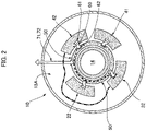
- FIG. 2 is an illustrative diagram showing one example of a case in which the rotary encoder 10 is incorporated into a large-sized hollow motor provided with an annular space 15A having a larger diameter than in the case shown in FIG. 1 .
- the mounting substrates 22, 32, 41, 42, the printed wiring substrate 50, and the inter-substrate wiring cables 60 can be used without modification. Even when the rotary encoder 10 is applied to a large-sized motor, it is possible to minimize the length of the wiring cables, and to satisfactorily maintain signal quality.
- the mounting substrates 42, 32 are interconnected using a wiring cable, the wiring length could increase, as indicated by the dash-dotted line in FIG. 2 .
- the wiring length can be dramatically shortened.
- the rotary encoder 10 described above is provided with four mounting substrates as encoder substrates.
- the number of mounting substrates is not limited to four.
- the mounting substrates are not limited to being of arcuate form.
- the annular printed wiring substrate was disposed on the radially inner side relative to the mounting substrates.
- the printed wiring substrate can also be disposed on the radially outer side relative to the mounting substrates. Additionally, the printed wiring substrate can be disposed on the side of the mounting substrates, i.e., adjacent to the mounting substrates in the direction of the central axis of the encoder.
Landscapes
- Engineering & Computer Science (AREA)
- Physics & Mathematics (AREA)
- General Physics & Mathematics (AREA)
- Power Engineering (AREA)
- Microelectronics & Electronic Packaging (AREA)
- Electromagnetism (AREA)
- Transmission And Conversion Of Sensor Element Output (AREA)
Abstract
Description
- The present invention relates to a rotary encoder that detects, inter alia, the rotational speed of a motor.
- Magnetic encoders, optical encoders, and other rotary encoders are used in order to detect the rotation states (speed, rotational angle, rotation position, etc.) of motors, etc. In the case of detecting the rotation state of, inter alia, a hollow shaft of a hollow motor, an annular space formed between the hollow shaft and a case surrounding the hollow shaft is used as a space for installation of substrates, wiring cables, and other constituent components of the rotary encoder.
-
FIG. 3 is an illustrative diagram showing the disposition state of, inter alia, encoder substrates of a rotary encoder in the case described above. As shown inFIG. 3 , encoder substrates 111-114 divided into a plurality of units are disposed in anannular space 103 formed between a hollow rotatingshaft 101 and acylindrical case 102 in a state in which the encoder substrates 111-114 surround the outer periphery of the hollow rotatingshaft 101. The encoder substrates 111-114 include a detection element mounting substrate on which is mounted a magnetic detection element or other detection element, a signal processing substrate on which is mounted a signal-processing module that generates encoded signals having a different phase than the detection signals from the detection element, an interface substrate on which is mounted an interface circuit that transmits and receives signals to and from an external unit, etc. Power-supply wiring cables, signal-transmitting-and-receiving wiring cables, etc., from the exterior are connected to these encoder substrates 111-114. For example,adjacent encoder substrates wiring cable 121.Encoder substrates wiring cable 122. A power-supply wiring cable 123 is drawn in from outside of thecase 102, and anoutput wiring cable 124 for outputting encoder output signals is drawn out to the exterior of the case. - Patent document 1 proposes a magnetic absolute encoder that is used attached to a motor. In the magnetic absolute encoder disclosed in Patent document 1, one flexible printed wiring substrate (encoder substrate) on which are mounted a plurality of magnetic detection elements is disposed in a loop so as to surround a two-pole magnet and a multi-pole magnet. This makes it possible to omit an operation for assembling a plurality of encoder substrates on which magnetic detection elements are mounted, and makes it possible to easily carry out an operation for positioning the magnetic detection elements and an operation for hard-wiring wirings drawn out from encoder substrates.
Patent document 2 proposes a rotation detection device that is suited to being incorporated in a narrow annular gap within a hollow actuator, etc. In this rotation detection device, there is employed a configuration in which a plurality of rigid substrates are joined in a circumferential direction. -
- Patent document 1:
WO2011/061794 - Patent document 2:
WO2017/212654 - The following problems are presented in a rotary encoder provided with the prior-art encoder substrates and wiring shown in
FIG. 3 . Firstly, when the annular space serving as the installation space is narrow, inter-substrate wiring cables are diverted from and routed around the edges of the encoder substrates. It is necessary to ensure a space for routing the cables in the narrow annular space. Additionally, effort is required in an operation for connecting the inter-substrate wiring cables. Moreover, there are also concerns regarding deterioration in the quality of signals transferred via the wiring cables that are diverted from and routed around the substrates. - Secondly, when the encoder substrates are wired and interconnected within an annular space having a narrow radialdirection width, it is difficult to ensure a space for drawing out the wiring cables from the radially outer or inner side, and the wiring cables are drawn out in the circumferential direction. In this case, cable connectors are mounted on the substrates in a state of facing in the circumferential direction. It is necessary to set adjacent substrates apart from each other in order to ensure the space for disposing the cable connectors and the wiring cables between the adjacent substrates. Additionally, when the gaps between adjacent substrates are narrow, it is necessary to use special jigs in a wiring operation. Therefore, the usage efficiency of the narrow annular space is poor.
- Thirdly, when standard encoder substrates are assembled in motors of different sizes, it is necessary to change the length of inter-substrate wiring cables for each size of motor. It is impossible to standardize or harmonize the cables, and the cost advantages of substrate standardization decrease.
- By contrast, in the magnetic absolute encoder disclosed in Patent document 1, there is used a single flexible printed wiring substrate (encoder substrate) that is specially designed for each size of motor being assembled. It is unnecessary to route wiring cables, and it is also easy to carry out operations for routing and hard-wiring inter-substrate wiring cables. However, in the case of use in motors of different sizes, a disadvantage is presented in that it is impossible to standardize the encoder substrate.
- In the rotation detection device disclosed in
Patent document 2, there is used an encoder substrate configured by annularly joining a plurality of rigid substrates, the rotation detection device being suited to being incorporated in a narrow annular space. However, no consideration has been given to factors such as routing of wiring that is drawn out from the rigid substrates, and wiring and joining between rigid substrates that are located apart from each other. - In view of the foregoing, it is an object of the present invention to provide a rotary encoder that is suited to being incorporated in a narrow annular space, the rotary encoder facilitating operations for routing and hard-wiring inter-substrate wiring cables, and enabling standardized use even in motors of different sizes.
- In order to resolve the problems described above, the rotary encoder according to the present invention has an encoder circuit substrate provided with a plurality of mounting substrates, an annular printed wiring substrate, and inter-substrate wiring cables that interconnect the printed wiring substrate and each of the mounting substrates. The mounting substrates that are adjacent to the printed wiring substrate on the radially outer or inner side thereof, or that are adjacent thereto in the direction of a central axis, are positioned along the printed wiring substrate in the circumferential direction thereof. The inter-substrate wiring cables are bridged in the radial direction, or in the direction of the central axis, between the printed wiring substrate and each of the mounting substrates. The printed wiring substrate is provided with a wiring pattern for supplying power to each of the mounting substrates, and a wiring pattern for transferring signals between at least two of the mounting substrates.
- In the rotary encoder according to the present invention, the mounting substrates are interconnected via the annular printed wiring substrate. The wiring pattern for supplying power to the mounting substrates is printed on the printed wiring substrate. Externally supplied electric power is distributed to the mounting substrates via the power-supply wiring pattern of the printed wiring substrate. It is unnecessary for power-supply wiring cables in a number corresponding to the plurality of mounting substrates to be diverted from and routed around the edges of the mounting substrates arranged in the circumferential direction. Additionally, the signal-transfer wiring pattern for interconnecting the mounting substrates is printed on the printed wiring substrate. It is unnecessary to route wiring cables for interconnecting the mounting substrates located apart from each other in the circumferential direction. Thus, the need for a space for installation of power-supply wiring cables and signal-transfer wiring cables, and the need for an operation for installing these cables, are both obviated.
- Additionally, the mounting substrates and the printed wiring substrate are interconnected by the inter-substrate wiring cables bridged in the radial direction, or in the direction of the central axis, between the mounting substrates and the printed wiring substrate. It is unnecessary to widen the gap between adjacent mounting substrates in the circumferential direction to ensure a wiring space. Additionally, because it is unnecessary for long wiring cables to be routed in the circumferential direction, it is possible to minimize any deterioration in the quality of signals being transferred.
- Furthermore, it is easy to standardize the mounting substrates, the printed wiring substrate, and the inter-substrate wiring cables among rotary encoders used in motors of different sizes.
- It is desirable for the mounting substrates to be disposed on the radially outer side of the annular printed wiring substrate. Disposing the printed wiring substrate on the inner side relative to the mounting substrates makes it possible to reduce the outside-diameter dimensions of the printed wiring substrate and to reduce the circumference thereof. This makes it possible to reduce the length of a wiring pattern extending in the circumferential direction on the printed wiring substrate in order to interlink the mounting substrates.
- The rotary encoder according to the present invention is suited to being incorporated in an annular space. The annular space is formed between a hollow rotating shaft and an encoder case that surrounds the hollow rotating shaft.
- When the rotary encoder according to the present invention is incorporated into a motor, or into an actuator provided with a motor and a reducer, the rotary encoder can be directly incorporated into an annular space between a motor shaft and a motor case, or into an annular space between a reducer output shaft and a reducer case.
-
-
FIG. 1(a) is a schematic diagram showing a hollow motor provided with a rotary encoder to which the present invention is applied, andFIG. 1(b) is an illustrative diagram showing the arrangement state of mounting substrates, etc., of the rotary encoder; -
FIG. 2 is an illustrative diagram showing the effect of the rotary encoder inFIG. 1 ; and -
FIG. 3 is an illustrative diagram showing the arrangement state of mounting substrates of a prior-art rotary encoder. - A hollow motor provided with a rotary encoder according to embodiments of the present invention is described below with reference to the accompanying drawings.
-
FIG. 1(a) is a schematic diagram showing the hollow motor, andFIG. 1(b) is an illustrative diagram showing the arrangement state of an encoder substrate, etc., of the rotary encoder. The hollow motor 1 is provided with acylindrical motor case 2. Ahollow motor shaft 3 that extends through the center of themotor case 2 is disposed inside themotor case 2. Thehollow motor shaft 3 is rotatably supported, at portions located to the front and rear along the direction of acentral axis 1a, by themotor case 2 via bearings. A motor rotor (not shown) is attached to thehollow motor shaft 3, and a motor stator (not shown) is attached to the side of themotor case 2 in a state of coaxially surrounding the motor rotor. - A
rotary encoder 10 is attached to the rear end of themotor case 2. Therotary encoder 10 is provided with a hollowrotating shaft 11 that is formed integrally with an axial end section of thehollow motor shaft 3, and a cup-shapedencoder case 12 that surrounds the hollow rotatingshaft 11. A circularhollow section 14 that extends through a central portion of the motor in the direction of thecentral axis 1a is formed by thehollow motor shaft 3 and the hollow rotatingshaft 11. Additionally, in therotary encoder 10, anannular space 15 is formed between the hollow rotatingshaft 11 and acylindrical portion 12a of theencoder case 12. The constituent components of therotary encoder 10 are incorporated into theannular space 15. - An actuator provided with the rotary encoder according to the present invention is configured such that, for example, a
reducer 90 is assembled at the front portion of the hollow motor 1, as indicated by virtual lines inFIG. 1(a) . For example, a strain wave gearing is used as thereducer 90. In the case of a hollow actuator, a hollow reducer provided with ahollow section 91 extending through the center thereof is used as thereducer 90. An actuator hollow section extending through the center of the actuator is formed by thehollow section 91 and the circularhollow section 14 of the hollow motor 1. - In the hollow motor 1, the
rotary encoder 10 is, e.g., an absolute encoder provided with amagnetic encoder section 20 and anoptical encoder section 30. Themagnetic encoder section 20 is provided with a two-polemagnetized magnet ring 21 that is coaxially secured to the hollow rotatingshaft 11, and a mounting substrate 22 (MT substrate) that is attached to the side of theencoder case 12. A magnetic sensor such as a Hall element, or another electronic component, is mounted on the mountingsubstrate 22. Theoptical encoder section 30 is provided with aslit disc 31 that is coaxially attached to the hollow rotatingshaft 11, and a mounting substrate 32 (ST substrate) that is attached to the side of theencoder case 12. A light-emitting element, a light-receiving element, a control circuit component for these elements, etc., is mounted on the mountingsubstrate 32. - The
rotary encoder 10 is additionally provided with: a mountingsubstrate 41 on which is mounted, for example, an electronic component constituting, inter alia, a signal processing circuit for processing detection signals obtained from themagnetic encoder section 20 and theoptical encoder section 30; and a mountingsubstrate 42 on which is mounted, for example, an electronic component constituting, inter alia, an interface circuit that transmits and receives signals to and from an external unit. - The
rotary encoder 10 is furthermore provided with: an annular printedwiring substrate 50 on which wiring patterns for interconnecting the mountingsubstrates terminal section 70 to which are connected fourinter-substrate wiring cables 60 that interconnect the printedwiring substrate 50 and each of the mountingsubstrates substrates substrates wiring substrate 50. - The annular printed
wiring substrate 50 is disposed in a state of coaxially surrounding the hollow rotatingshaft 11. The mountingsubstrates annular space 15, the mountingsubstrates wiring substrate 50. The four mountingsubstrates wiring substrate 50 are attached to substrate supports 80 that are attached to theencoder case 12. - In the printed
wiring substrate 50,cable connectors 61 are mounted at locations respectively facing each of the mountingsubstrates cable connectors 61 face radially outward.Cable connectors 62 are mounted on the mountingsubstrates cable connectors 62 face radially inward. Theinter-substrate wiring cables 60 are bridged in the radial direction between thecable connectors 61 of the printedwiring substrate 50 and thecable connectors 62 of the mountingsubstrates - In the
rotary encoder 10 according to the present example, an A-phase signal and a B-phase signal are generated respectively on the basis of detection signals from themagnetic encoder section 20 and theoptical encoder section 30. The absolute rotational position of thehollow motor shaft 3 within a single rotation, the number of rotations of thehollow motor shaft 3 from an origin-point position, etc., are calculated on the basis of these encoder signals. - The
rotary encoder 10 according to the present example is provided with the plurality of mountingsubstrates wiring substrate 50 that is disposed on the radially inner side of the plurality of mountingsubstrates inter-substrate wiring cables 60 interlinking the mountingsubstrates wiring substrate 50, these components being provided within theannular space 15. Unlike the prior-art case shown inFIG. 3 , it is unnecessary for wiring cables for connecting the mountingsubstrates wiring substrate 50. - For example, externally supplied electric power is distributed to the mounting
substrates wiring substrate 50. The need for wiring cables for supplying electric power, etc., to the mounting substrates, and the need for a space for installation of such wiring cables, are both obviated. An operation for hard-wiring a plurality of divided substrates disposed in the narrowannular space 15 is facilitated, and any deterioration in the quality of signals transferred via long wiring cables can be minimized. - It is also unnecessary to ensure space for disposing cable connectors, wiring cables, etc., between adjacent mounting
substrates annular space 15 can be effectively utilized. - Furthermore, the mounting
substrates wiring substrate 50 from the radially outer side. Because the cable connectors are to be attached to and detached from the printed wiring substrate and the divided substrates from the radial direction, the cable connectors are easily attached and detached. - In the case of a rotary encoder having the prior-art configuration shown in
FIG. 3 , it is necessary to specially design wiring cable lengths for each size of motor. Additionally, when the rotary encoder is applied to a smallsized motor, the degree of freedom in design decreases because it is necessary to design the rotary encoder in consideration of a mounting area for the cable connectors. Moreover, as a result of increases in cable length in a large-sized motor, the risk of deterioration in the quality of signals increases. However, therotary encoder 10 according to the present example presents advantages in that the components thereof (divided substrates, printed wiring substrate, and inter-substrate wiring cables) can be standardized and in that production management is facilitated, irrespective of the size of the motor. -
FIG. 2 is an illustrative diagram showing one example of a case in which therotary encoder 10 is incorporated into a large-sized hollow motor provided with anannular space 15A having a larger diameter than in the case shown inFIG. 1 . The mountingsubstrates wiring substrate 50, and theinter-substrate wiring cables 60 can be used without modification. Even when therotary encoder 10 is applied to a large-sized motor, it is possible to minimize the length of the wiring cables, and to satisfactorily maintain signal quality. For example, when the mountingsubstrates FIG. 2 . In the present example, because the substrates are connected via the annular printedwiring substrate 50 as indicated by the dashed line, the wiring length can be dramatically shortened. - Although a hollow motor provided with a rotary encoder to which the present invention is applied was described above, it shall be apparent that the rotary encoder according to the present invention can be applied in a similar manner to a hollow actuator provided with a hollow motor and a hollow strain wave gearing or other hollow gear drive.
- Additionally, the
rotary encoder 10 described above is provided with four mounting substrates as encoder substrates. The number of mounting substrates is not limited to four. Moreover, the mounting substrates are not limited to being of arcuate form. - Furthermore, in the example described above, the annular printed wiring substrate was disposed on the radially inner side relative to the mounting substrates. The printed wiring substrate can also be disposed on the radially outer side relative to the mounting substrates. Additionally, the printed wiring substrate can be disposed on the side of the mounting substrates, i.e., adjacent to the mounting substrates in the direction of the central axis of the encoder.
Claims (12)
- A rotary encoder comprising:an encoder circuit substrate provided with a plurality of mounting substrates;an annular printed wiring substrate; andinter-substrate wiring cables that interconnect the printed wiring substrate and each of the mounting substrates,wherein the mounting substrates are positioned adjacent to the printed wiring substrate on a radially outer or inner side thereof, or adjacent thereto in a direction of a central axis, and are arranged along the printed wiring substrate in a circumferential direction thereof;the inter-substrate wiring cables are bridged in the radial direction, or in the direction of the central axis, between the printed wiring substrate and each of the mounting substrates; andthe printed wiring substrate is provided with a wiring pattern for supplying power to each of the mounting substrates, and a wiring pattern for transferring signals between at least two of the mounting substrates.
- The rotary encoder according to claim 1,
wherein the mounting substrates is disposed on the radially outer side of the printed wiring substrate. - The rotary encoder according to claim 1, further comprising:a hollow rotating shaft;an encoder case that surrounds the hollow rotating shaft; andan annular space formed between the hollow rotating shaft and the encoder case,wherein the printed wiring substrate, the mounting substrate and the inter-substrate wiring cables are disposed in the annular space.
- The rotary encoder according to claim 2, further comprising:a hollow rotating shaft;an encoder case that surrounds the hollow rotating shaft; andan annular space formed between the hollow rotating shaft and the encoder case,wherein the printed wiring substrate, the mounting substrate and the inter-substrate wiring cables are disposed in the annular space.
- A motor comprising:a motor output shaft; andthe rotary encoder according to claim 1 to detect rotational information of the motor output shaft.
- The motor according to claim 5,
wherein the mounting substrate is disposed on the radially outer side of the printed wiring substrate. - The motor according to claim 5, further comprising:a hollow rotating shaft;an encoder case that surrounds the hollow rotating shaft; andan annular space formed between the hollow rotating shaft and the encoder case,wherein the printed wiring substrate, the mounting substrate and the inter-substrate wiring cables are disposed in the annular space.
- The motor according to claim 6, further comprising:a hollow rotating shaft;an encoder case that surrounds the hollow rotating shaft; andan annular space formed between the hollow rotating shaft and the encoder case,wherein the printed wiring substrate, the mounting substrate and the inter-substrate wiring cables are disposed in the annular space.
- An actuator comprising:a motor;a reducer to reduce speed of output rotation of the motor; andthe rotary encoder according to claim 1 to detect rotational information of an output shaft of the reducer.
- The actuator according to claim 9,
wherein the mounting substrate is disposed on the radially outer side of the printed wiring substrate. - The actuator according to claim 9, further comprising:a hollow rotating shaft;an encoder case that surrounds the hollow rotating shaft; andan annular space formed between the hollow rotating shaft and the encoder case,wherein the printed wiring substrate, the mounting substrate and the inter-substrate wiring cables are disposed in the annular space.
- The actuator according to claim 10, further comprising:a hollow rotating shaft;an encoder case that surrounds the hollow rotating shaft; andan annular space formed between the hollow rotating shaft and the encoder case,wherein the printed wiring substrate, the mounting substrate and the inter-substrate wiring cables are disposed in the annular space.
Applications Claiming Priority (1)
| Application Number | Priority Date | Filing Date | Title |
|---|---|---|---|
| PCT/JP2020/017862 WO2021215013A1 (en) | 2020-04-24 | 2020-04-24 | Rotary encoder |
Publications (4)
| Publication Number | Publication Date |
|---|---|
| EP4086585A1 true EP4086585A1 (en) | 2022-11-09 |
| EP4086585A4 EP4086585A4 (en) | 2023-08-23 |
| EP4086585C0 EP4086585C0 (en) | 2024-11-13 |
| EP4086585B1 EP4086585B1 (en) | 2024-11-13 |
Family
ID=78270704
Family Applications (1)
| Application Number | Title | Priority Date | Filing Date |
|---|---|---|---|
| EP20931806.2A Active EP4086585B1 (en) | 2020-04-24 | 2020-04-24 | Rotary encoder |
Country Status (7)
| Country | Link |
|---|---|
| US (1) | US12203746B2 (en) |
| EP (1) | EP4086585B1 (en) |
| JP (1) | JP7301488B2 (en) |
| KR (1) | KR102920499B1 (en) |
| CN (1) | CN115362350A (en) |
| TW (1) | TWI885065B (en) |
| WO (1) | WO2021215013A1 (en) |
Cited By (1)
| Publication number | Priority date | Publication date | Assignee | Title |
|---|---|---|---|---|
| US20240058949A1 (en) * | 2021-01-11 | 2024-02-22 | Schaeffler Technologies AG & Co. KG | Robot, drive unit for a robot and positioning method |
Families Citing this family (1)
| Publication number | Priority date | Publication date | Assignee | Title |
|---|---|---|---|---|
| JP2024148814A (en) * | 2023-04-06 | 2024-10-18 | 株式会社ミツトヨ | MEASURING APPARATUS AND ABSOLUTE ANGLE IDENTIFICATION METHOD |
Family Cites Families (19)
| Publication number | Priority date | Publication date | Assignee | Title |
|---|---|---|---|---|
| US5038031A (en) * | 1989-06-22 | 1991-08-06 | Optec D.D. Melco Laboratory Co., Ltd. | Optical rotary encoder having large and small numerical aperture fibers |
| US7312595B2 (en) | 2002-07-09 | 2007-12-25 | Denso Corporation | Motor control apparatus |
| JP3886042B2 (en) | 2002-07-09 | 2007-02-28 | 株式会社デンソー | Motor control device |
| US7973503B2 (en) * | 2007-06-26 | 2011-07-05 | Wooward HRT, Inc. | Motor system employing analog encoded hall effect sensor position information for reduced wiring |
| JP4940035B2 (en) | 2007-07-06 | 2012-05-30 | セイコーインスツル株式会社 | Angular velocity sensor and method of manufacturing angular velocity sensor |
| US8310228B2 (en) * | 2008-11-12 | 2012-11-13 | Aisan Kogyo Kabushiki Kaisha | Resolver |
| US8847585B2 (en) | 2009-11-18 | 2014-09-30 | Harmonic Drive Systems Inc. | Magnetic absolute encoder and motor |
| KR101068085B1 (en) | 2009-12-02 | 2011-09-28 | 주식회사에이치에스엠엔조이워터 | Underwater Cable Capsule Car Shifter |
| JP2012220192A (en) | 2011-04-04 | 2012-11-12 | Ntn Corp | Roller bearing device having rotation detection function |
| JP2014062770A (en) | 2012-09-20 | 2014-04-10 | Nikon Corp | Encoder, encoder assembling method, drive device, and robot device |
| JP6239824B2 (en) * | 2013-01-18 | 2017-11-29 | 株式会社ミツトヨ | Inductive detection type rotary encoder |
| JP2014202704A (en) * | 2013-04-09 | 2014-10-27 | 三菱電機株式会社 | Magnetic field detection device |
| JP5763810B1 (en) | 2014-06-03 | 2015-08-12 | 栄通信工業株式会社 | Contactless potentiometer |
| JP6447715B2 (en) * | 2015-03-31 | 2019-01-09 | 株式会社村田製作所 | Rotary electronic components and rotary encoders |
| CN107850466B (en) * | 2015-07-17 | 2021-01-08 | 株式会社尼康 | Encoder device, drive device, rotation information acquisition method, and recording medium |
| JP2017212654A (en) | 2016-05-26 | 2017-11-30 | 株式会社エクスビジョン | Gui apparatus |
| KR102065017B1 (en) * | 2016-06-10 | 2020-01-10 | 가부시키가이샤 하모닉 드라이브 시스템즈 | Rotary Detection Device and Hollow Actuator |
| DE102017107716B4 (en) * | 2017-04-03 | 2018-11-29 | Trafag Ag | Torque transmitter and torque sensor as well as manufacturing methods and measuring methods |
| JP2019138720A (en) | 2018-02-08 | 2019-08-22 | イビデン株式会社 | Encoder substrate |
-
2020
- 2020-04-24 JP JP2022516822A patent/JP7301488B2/en active Active
- 2020-04-24 EP EP20931806.2A patent/EP4086585B1/en active Active
- 2020-04-24 WO PCT/JP2020/017862 patent/WO2021215013A1/en not_active Ceased
- 2020-04-24 CN CN202080097029.XA patent/CN115362350A/en active Pending
- 2020-04-24 US US17/758,245 patent/US12203746B2/en active Active
- 2020-04-24 KR KR1020227025590A patent/KR102920499B1/en active Active
-
2021
- 2021-02-19 TW TW110105639A patent/TWI885065B/en active
Cited By (2)
| Publication number | Priority date | Publication date | Assignee | Title |
|---|---|---|---|---|
| US20240058949A1 (en) * | 2021-01-11 | 2024-02-22 | Schaeffler Technologies AG & Co. KG | Robot, drive unit for a robot and positioning method |
| US12472623B2 (en) * | 2021-01-11 | 2025-11-18 | Schaeffler Technologies AG & Co. KG | Robot, drive unit for a robot and positioning method |
Also Published As
| Publication number | Publication date |
|---|---|
| JP7301488B2 (en) | 2023-07-03 |
| EP4086585A4 (en) | 2023-08-23 |
| JPWO2021215013A1 (en) | 2021-10-28 |
| EP4086585C0 (en) | 2024-11-13 |
| KR102920499B1 (en) | 2026-01-29 |
| WO2021215013A1 (en) | 2021-10-28 |
| CN115362350A (en) | 2022-11-18 |
| TWI885065B (en) | 2025-06-01 |
| TW202141897A (en) | 2021-11-01 |
| US20230048463A1 (en) | 2023-02-16 |
| EP4086585B1 (en) | 2024-11-13 |
| US12203746B2 (en) | 2025-01-21 |
| KR20220116299A (en) | 2022-08-22 |
Similar Documents
| Publication | Publication Date | Title |
|---|---|---|
| US8159096B2 (en) | Apparatus for detecting position of rotation of motor | |
| EP3276209B1 (en) | Servomotor and control method thereof | |
| JP5540981B2 (en) | Articulated robot | |
| US10483823B2 (en) | Electric actuator | |
| EP4086585B1 (en) | Rotary encoder | |
| US11408485B2 (en) | Electric actuator | |
| WO2016098627A1 (en) | Rotation-angle detection device and power steering device | |
| JP5328932B2 (en) | Magnetic absolute encoder and motor | |
| EP3470795B1 (en) | Rotation detecting device and hollow actuator | |
| US20190203825A1 (en) | Actuator | |
| CN101680512A (en) | Reduction gear with motor and industrial machine | |
| JP2018126032A (en) | Electric actuator | |
| JP6559370B1 (en) | Encoder and servo motor | |
| KR102803198B1 (en) | Servo motors and robotic devices | |
| JP2014058251A (en) | Electric caster | |
| CN211701704U (en) | Motor with a stator having a stator core | |
| JP3533375B2 (en) | Rotary non-contact connector | |
| JP2007325479A (en) | Multi-driving motor | |
| KR102664783B1 (en) | Sbw actuator | |
| JP2023066464A (en) | Eccentric oscillation type gear device | |
| WO2025191745A1 (en) | Torque sensor |
Legal Events
| Date | Code | Title | Description |
|---|---|---|---|
| STAA | Information on the status of an ep patent application or granted ep patent |
Free format text: STATUS: THE INTERNATIONAL PUBLICATION HAS BEEN MADE |
|
| PUAI | Public reference made under article 153(3) epc to a published international application that has entered the european phase |
Free format text: ORIGINAL CODE: 0009012 |
|
| STAA | Information on the status of an ep patent application or granted ep patent |
Free format text: STATUS: REQUEST FOR EXAMINATION WAS MADE |
|
| 17P | Request for examination filed |
Effective date: 20220712 |
|
| AK | Designated contracting states |
Kind code of ref document: A1 Designated state(s): AL AT BE BG CH CY CZ DE DK EE ES FI FR GB GR HR HU IE IS IT LI LT LU LV MC MK MT NL NO PL PT RO RS SE SI SK SM TR |
|
| REG | Reference to a national code |
Ref country code: DE Free format text: PREVIOUS MAIN CLASS: G01D0005245000 Ref country code: DE Ref legal event code: R079 Ref document number: 602020041498 Country of ref document: DE Free format text: PREVIOUS MAIN CLASS: G01D0005245000 Ipc: G01D0005244000 |
|
| DAV | Request for validation of the european patent (deleted) | ||
| DAX | Request for extension of the european patent (deleted) | ||
| A4 | Supplementary search report drawn up and despatched |
Effective date: 20230720 |
|
| RIC1 | Information provided on ipc code assigned before grant |
Ipc: H05K 3/36 20060101ALI20230714BHEP Ipc: G01D 5/244 20060101AFI20230714BHEP |
|
| GRAP | Despatch of communication of intention to grant a patent |
Free format text: ORIGINAL CODE: EPIDOSNIGR1 |
|
| GRAP | Despatch of communication of intention to grant a patent |
Free format text: ORIGINAL CODE: EPIDOSNIGR1 |
|
| STAA | Information on the status of an ep patent application or granted ep patent |
Free format text: STATUS: GRANT OF PATENT IS INTENDED |
|
| RIC1 | Information provided on ipc code assigned before grant |
Ipc: H05K 3/36 20060101ALI20240527BHEP Ipc: G01D 5/244 20060101AFI20240527BHEP |
|
| INTG | Intention to grant announced |
Effective date: 20240614 |
|
| GRAS | Grant fee paid |
Free format text: ORIGINAL CODE: EPIDOSNIGR3 |
|
| GRAA | (expected) grant |
Free format text: ORIGINAL CODE: 0009210 |
|
| STAA | Information on the status of an ep patent application or granted ep patent |
Free format text: STATUS: THE PATENT HAS BEEN GRANTED |
|
| AK | Designated contracting states |
Kind code of ref document: B1 Designated state(s): AL AT BE BG CH CY CZ DE DK EE ES FI FR GB GR HR HU IE IS IT LI LT LU LV MC MK MT NL NO PL PT RO RS SE SI SK SM TR |
|
| REG | Reference to a national code |
Ref country code: GB Ref legal event code: FG4D |
|
| REG | Reference to a national code |
Ref country code: CH Ref legal event code: EP |
|
| REG | Reference to a national code |
Ref country code: IE Ref legal event code: FG4D |
|
| REG | Reference to a national code |
Ref country code: DE Ref legal event code: R096 Ref document number: 602020041498 Country of ref document: DE |
|
| U01 | Request for unitary effect filed |
Effective date: 20241206 |
|
| U07 | Unitary effect registered |
Designated state(s): AT BE BG DE DK EE FI FR IT LT LU LV MT NL PT RO SE SI Effective date: 20241217 |
|
| PG25 | Lapsed in a contracting state [announced via postgrant information from national office to epo] |
Ref country code: HR Free format text: LAPSE BECAUSE OF FAILURE TO SUBMIT A TRANSLATION OF THE DESCRIPTION OR TO PAY THE FEE WITHIN THE PRESCRIBED TIME-LIMIT Effective date: 20241113 Ref country code: IS Free format text: LAPSE BECAUSE OF FAILURE TO SUBMIT A TRANSLATION OF THE DESCRIPTION OR TO PAY THE FEE WITHIN THE PRESCRIBED TIME-LIMIT Effective date: 20250313 |
|
| PG25 | Lapsed in a contracting state [announced via postgrant information from national office to epo] |
Ref country code: ES Free format text: LAPSE BECAUSE OF FAILURE TO SUBMIT A TRANSLATION OF THE DESCRIPTION OR TO PAY THE FEE WITHIN THE PRESCRIBED TIME-LIMIT Effective date: 20241113 |
|
| PG25 | Lapsed in a contracting state [announced via postgrant information from national office to epo] |
Ref country code: NO Free format text: LAPSE BECAUSE OF FAILURE TO SUBMIT A TRANSLATION OF THE DESCRIPTION OR TO PAY THE FEE WITHIN THE PRESCRIBED TIME-LIMIT Effective date: 20250213 |
|
| PG25 | Lapsed in a contracting state [announced via postgrant information from national office to epo] |
Ref country code: GR Free format text: LAPSE BECAUSE OF FAILURE TO SUBMIT A TRANSLATION OF THE DESCRIPTION OR TO PAY THE FEE WITHIN THE PRESCRIBED TIME-LIMIT Effective date: 20250214 |
|
| PG25 | Lapsed in a contracting state [announced via postgrant information from national office to epo] |
Ref country code: PL Free format text: LAPSE BECAUSE OF FAILURE TO SUBMIT A TRANSLATION OF THE DESCRIPTION OR TO PAY THE FEE WITHIN THE PRESCRIBED TIME-LIMIT Effective date: 20241113 |
|
| PG25 | Lapsed in a contracting state [announced via postgrant information from national office to epo] |
Ref country code: RS Free format text: LAPSE BECAUSE OF FAILURE TO SUBMIT A TRANSLATION OF THE DESCRIPTION OR TO PAY THE FEE WITHIN THE PRESCRIBED TIME-LIMIT Effective date: 20250213 |
|
| U20 | Renewal fee for the european patent with unitary effect paid |
Year of fee payment: 6 Effective date: 20250425 |
|
| PG25 | Lapsed in a contracting state [announced via postgrant information from national office to epo] |
Ref country code: SM Free format text: LAPSE BECAUSE OF FAILURE TO SUBMIT A TRANSLATION OF THE DESCRIPTION OR TO PAY THE FEE WITHIN THE PRESCRIBED TIME-LIMIT Effective date: 20241113 |
|
| PG25 | Lapsed in a contracting state [announced via postgrant information from national office to epo] |
Ref country code: SK Free format text: LAPSE BECAUSE OF FAILURE TO SUBMIT A TRANSLATION OF THE DESCRIPTION OR TO PAY THE FEE WITHIN THE PRESCRIBED TIME-LIMIT Effective date: 20241113 |
|
| PG25 | Lapsed in a contracting state [announced via postgrant information from national office to epo] |
Ref country code: CZ Free format text: LAPSE BECAUSE OF FAILURE TO SUBMIT A TRANSLATION OF THE DESCRIPTION OR TO PAY THE FEE WITHIN THE PRESCRIBED TIME-LIMIT Effective date: 20241113 |
|
| PLBE | No opposition filed within time limit |
Free format text: ORIGINAL CODE: 0009261 |
|
| STAA | Information on the status of an ep patent application or granted ep patent |
Free format text: STATUS: NO OPPOSITION FILED WITHIN TIME LIMIT |
|
| 26N | No opposition filed |
Effective date: 20250814 |
|
| REG | Reference to a national code |
Ref country code: CH Ref legal event code: H13 Free format text: ST27 STATUS EVENT CODE: U-0-0-H10-H13 (AS PROVIDED BY THE NATIONAL OFFICE) Effective date: 20251125 |
|
| PG25 | Lapsed in a contracting state [announced via postgrant information from national office to epo] |
Ref country code: MC Free format text: LAPSE BECAUSE OF FAILURE TO SUBMIT A TRANSLATION OF THE DESCRIPTION OR TO PAY THE FEE WITHIN THE PRESCRIBED TIME-LIMIT Effective date: 20241113 |
|
| PG25 | Lapsed in a contracting state [announced via postgrant information from national office to epo] |
Ref country code: CH Free format text: LAPSE BECAUSE OF NON-PAYMENT OF DUE FEES Effective date: 20250430 |
|
| PGFP | Annual fee paid to national office [announced via postgrant information from national office to epo] |
Ref country code: GB Payment date: 20260313 Year of fee payment: 7 |
|
| PG25 | Lapsed in a contracting state [announced via postgrant information from national office to epo] |
Ref country code: IE Free format text: LAPSE BECAUSE OF NON-PAYMENT OF DUE FEES Effective date: 20250424 |
|
| U20 | Renewal fee for the european patent with unitary effect paid |
Year of fee payment: 7 Effective date: 20260310 |