EP4086504B1 - Leuchte und leuchtenkombination - Google Patents
Leuchte und leuchtenkombination Download PDFInfo
- Publication number
- EP4086504B1 EP4086504B1 EP21189097.5A EP21189097A EP4086504B1 EP 4086504 B1 EP4086504 B1 EP 4086504B1 EP 21189097 A EP21189097 A EP 21189097A EP 4086504 B1 EP4086504 B1 EP 4086504B1
- Authority
- EP
- European Patent Office
- Prior art keywords
- hinge
- connector
- plate
- luminaire
- housing
- Prior art date
- Legal status (The legal status is an assumption and is not a legal conclusion. Google has not performed a legal analysis and makes no representation as to the accuracy of the status listed.)
- Active
Links
Images


Classifications
-
- F—MECHANICAL ENGINEERING; LIGHTING; HEATING; WEAPONS; BLASTING
- F21—LIGHTING
- F21S—NON-PORTABLE LIGHTING DEVICES; SYSTEMS THEREOF; VEHICLE LIGHTING DEVICES SPECIALLY ADAPTED FOR VEHICLE EXTERIORS
- F21S2/00—Systems of lighting devices, not provided for in main groups F21S4/00 - F21S10/00 or F21S19/00, e.g. of modular construction
- F21S2/005—Systems of lighting devices, not provided for in main groups F21S4/00 - F21S10/00 or F21S19/00, e.g. of modular construction of modular construction
-
- F—MECHANICAL ENGINEERING; LIGHTING; HEATING; WEAPONS; BLASTING
- F21—LIGHTING
- F21V—FUNCTIONAL FEATURES OR DETAILS OF LIGHTING DEVICES OR SYSTEMS THEREOF; STRUCTURAL COMBINATIONS OF LIGHTING DEVICES WITH OTHER ARTICLES, NOT OTHERWISE PROVIDED FOR
- F21V21/00—Supporting, suspending, or attaching arrangements for lighting devices; Hand grips
- F21V21/005—Supporting, suspending, or attaching arrangements for lighting devices; Hand grips for several lighting devices in an end-to-end arrangement, i.e. light tracks
-
- F—MECHANICAL ENGINEERING; LIGHTING; HEATING; WEAPONS; BLASTING
- F21—LIGHTING
- F21V—FUNCTIONAL FEATURES OR DETAILS OF LIGHTING DEVICES OR SYSTEMS THEREOF; STRUCTURAL COMBINATIONS OF LIGHTING DEVICES WITH OTHER ARTICLES, NOT OTHERWISE PROVIDED FOR
- F21V21/00—Supporting, suspending, or attaching arrangements for lighting devices; Hand grips
- F21V21/14—Adjustable mountings
- F21V21/30—Pivoted housings or frames
-
- F—MECHANICAL ENGINEERING; LIGHTING; HEATING; WEAPONS; BLASTING
- F21—LIGHTING
- F21W—INDEXING SCHEME ASSOCIATED WITH SUBCLASSES F21K, F21L, F21S and F21V, RELATING TO USES OR APPLICATIONS OF LIGHTING DEVICES OR SYSTEMS
- F21W2131/00—Use or application of lighting devices or systems not provided for in codes F21W2102/00-F21W2121/00
- F21W2131/40—Lighting for industrial, commercial, recreational or military use
- F21W2131/406—Lighting for industrial, commercial, recreational or military use for theatres, stages or film studios
Definitions
- the disclosure relates to the field of illumination devices, in particular to a luminaire and a luminaire combination.
- luminaire holders are generally mounted on supports or girders through brackets, and mounted with screws. Most of such products adopt a design of rotary mounting and use bolts as hinged bearings to adjust inclination of the luminaires. Most of such products use screw rods or handle screws which are used as brakes by loosening or tightening. Positioning brackets of the luminaires are almost all U-shaped or L-shaped. In order to mount the luminaires to the supports or the girders, the brackets of the luminaires generally adopt standard or customized threaded holes or through holes.
- US 9004 730 B2 relates to a lighting fixture including a hexagonal housing having six side walls. Each side wall has a slot formed therein. Two or more lighting fixtures may be joined together to form a modular arrangement of lighting fixtures in a plurality of configurations by using an interlock piece which slides into channels formed in facing side walls of adjacent lighting fixtures to hold the lighting fixtures together;
- the disclosure provides a luminaire and a luminaire combination, for reducing internal space occupied by a luminaire connection structure, expanding a reserved space in the luminaire, and achieving firm and reliable connection, and convenience in mounting and demounting.
- a luminaire in an aspect, includes a housing and a light source module received in the housing.
- the housing defines a connecting groove therein, where the connecting groove is in a flat strip shape and extends from an outer surface of the housing.
- the luminaire further includes a connector in a strip shape, where one end of the connecting groove is opened for insertion of the connector.
- the connecting groove is provided with a limit portion on each of two opposite side walls thereof, and a gap between each limit portion and a bottom surface of the connecting groove forms a channel guide.
- the connector is provided with a connecting portion on each of two opposite sides thereof. The connecting portion is operable to be inserted into and matched with the channel guide corresponding to the connecting portion, such that the connecting portion is limited in the channel guide corresponding to the connecting portion via the limit portion corresponding to the connecting portion.
- the housing is in columnar shape, a central axis of the housing coincides with a light outgoing direction of the light source module, and a length direction of the connecting groove is parallel to the central axis of the housing.
- the housing is in a rectangular columnar shape, and defines one connecting groove on each of four side faces of the housing.
- the connector defines a positioning screw hole therein.
- the positioning screw is operable to be in threaded connection with the positioning screw hole to allow an end portion of the positioning screw to be abutted against the bottom surface of the connecting groove, such that the connector is positioned in the connecting groove.
- the connector defines a connecting screw hole in a middle position along a length direction of the connector, and the connecting screw hole is located at a middle position between two connecting portions disposed on the two opposite sides of the connector.
- the luminaire further includes a handwheel, the handwheel is provided with a handle screw at a position of a central axis of the handwheel, and the handle screw is operable to be in threaded connection with the connecting screw hole.
- the connector is further provided with a fixing portion on each of the two opposite sides of the connector, and the fixing portion and the connecting portion cooperate to define a limit groove capable of accommodating the limit portion.
- the two fixing portions extend away from each other and are in a flat and straight shape.
- the two fixing portions extend from one side surface, away from the connecting portion, of the connector to form a flat straight surface.
- the fixing portion and the connecting portion are of the same shape and size, the fixing portion is operable to be inserted into and matched with the channel guide, such that the connector serves as a connecting pin for connecting the housing the luminaire to a housing of another luminaire.
- a luminaire combination in another aspect, includes at least two luminaires described above.
- the luminaire combination further includes at least one of a bracket, an adjusting plate, a hinge, and a cardan shaft.
- the bracket is a bent plate in an L shape and has two arms which serve as a base plate in a square shape and a connecting plate in a triangular shape, respectively.
- the connector of the luminaire is disposed at the connecting plate.
- the connecting plate defines a connecting hole at a tip end, away from the base plate, of the connecting plate.
- a handle screw of a handwheel penetrates the connecting hole to be in threaded connection with the connecting screw hole of the connector.
- the adjusting plate includes a first bearing plate in a rectangular shape, a second bearing plate, an adjusting handwheel, and a knurled screw.
- the first bearing plate and the second bearing plate are arranged in parallel.
- One connector of one luminaire is disposed at one short edge of the first bearing plate
- the second bearing plate is arranged at the other short edge of the first bearing plate and another connector is disposed at the second bearing plate.
- the first bearing plate defines a rotating through hole at a long edge thereof
- the second bearing plate defines a rotating screw hole at a position thereof corresponding to the rotating through hole
- the knurled screw penetrates the rotating through hole to be in threaded connection with the rotating screw hole, so as to form a hinge point between the first bearing plate and the second bearing plate.
- the first bearing plate defines a guide hole in an arc-strip shape
- the second bearing plate defines an adjusting screw hole at a position of the second bearing plate corresponding to the guide hole
- an adjusting screw rod is arranged at a position of a central axis of the adjusting handwheel, and the adjusting screw rod penetrates the guide holes to be in threaded connection with the adjusting screw hole.
- the hinge includes a first hinge plate, a second hinge plate, and a hinge handwheel, the first hinge plate and the second hinge plate are hinged at their edges.
- One connector of one luminaire is disposed at the first hinge plate and one connector of another luminaire is disposed at the second hinge plate, and a length direction of each connector is parallel to a pivot between the first hinge plate and the second hinge plate.
- a brake plate is fixed on the first hinge plate, wherein the brake plate is perpendicular to the pivot between the first hinge plate and the second hinge plate and defines a hinge hole in an arc-strip shape, and a portion of the second hinge plate corresponding to the hinge hole is bent and defines a hinge screw hole therein.
- a hinge screw rod is arranged at a position of a central axis of the hinge handwheel, where the hinge screw rod penetrates the hinge hole to be in threaded connection with the hinge screw hole.
- the cardan shaft includes a fixed end, two intermediate parts, and a free end sequentially rotationally connected.
- One wing handle screw is arranged between the fixed end and one intermediate part, one wing handle screw is arranged between the two intermediate parts, one wing handle screw is arranged between the other intermediate part and the free end, and the three wing handle screws provide three rotating shafts, and at least one of the three rotating shafts is perpendicular to the other two rotating shafts.
- the luminaire and the luminaire combination are provided. Since the connecting groove is a flat shape arranged along the outer surface of the housing, its flat geometric structure occupies a small internal space of the luminaire, an internal reserved space of the luminaire is large and square, and thus a large component can be assembled in the housing.
- the two connecting portions are respectively limited in the two channel guides, so that firm and reliable connection is achieved between the connector and the housing. Mounting and demounting of the connector and the housing are facilitated by an inserting manner.
- the entire luminaire may be connected to other supports, girders, or the luminaire via the connector.
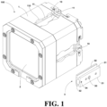
- the disclosure provides a luminaire 100 according to a preferred embodiment, including a housing 1, a light source module 2 arranged in the housing 1, and a connector 3.
- the housing 1 defines connecting grooves 10 therein, the connector 3 can be inserted into the connecting groove 10, so that detachable connection between the connector 3 and the housing 1 is realized.
- the connector 3 can be connected to other structural members such as a bracket to mount the luminaire 100 onto other objects such as a support or a girder.
- the connecting groove 10 is in a strip shape.
- the connecting groove 10 extends from an outer surface of the housing 1.
- the connecting groove 10 is flat.
- One end of the connecting groove 10 is opened for insertion of the connector 3.
- the connecting groove 10 is provided with a limit portion 11 on each of two opposite side walls of the connecting groove 10.
- a gap between each limit portion 11 and a bottom surface of the connecting groove 10 forms a channel guide 12.
- the connector 3 is in a strip shape.
- the connector 3 is provided with a connecting portion 31 on each of two opposite sides of the connector 3.
- the connecting portion 31 is operable to be inserted into and matched with the channel guide 12 corresponding to the connecting portion 31, such that the connecting portion 31 is limited in the channel guide 12 corresponding to the connecting portion 31 via the limit portions 11 corresponding to the connecting portion 31.
- the connecting groove 10 is a flat shape arranged along the outer surface of the housing 1, its flat geometric structure occupies a small internal space of the luminaire 100, an internal reserved space of the luminaire 100 is large and square, and thus a large component incapable of being reshaped or detached to fit a small or complicated space can be assembled in the housing 1.
- the connector 3 and the connecting groove 10 are in insertion matching. Through matching between the two connecting portions 31 and the two limit portions 11, the two connecting portions 31 are respectively limited in the two channel guides 12, so that firm and reliable connection is achieved between the connector 3 and the housing 1. Mounting and demounting of the connector 3 and the housing 1 are facilitated by an inserting manner.
- the entire luminaire 100 may be connected to other supports, girders, or the luminaire 100 through the connector 3.
- the connecting groove 10 described in the disclosure is flat, which involves that a groove depth D thereof is less than a groove width W Due to the small groove depth D, the internal space of the luminaire 100 occupied by the connecting groove 10 is reduced; due to the relatively large groove width W, the structure of the limit portions 11 and the channel guides 12 in a width direction of the connecting groove 10 can be used to achieve a connection with the connector 3, thereby making a full use of the space along the surface of the housing 1.
- the groove width W of the connecting groove 10 is 2.5 to 3.5 times of the groove depth D, and is 1.5 to 2.5 times of a gap X between the two limit portions 11, so that the structure of the connecting groove 10 may be as flat as possible, while connection strength between the connecting groove 10 and the connector 30 is ensured.
- the limit portion 11 has a channel guide face 11a, and the channel guide face 11 faces a bottom surface 10a of the connecting groove 10.
- the channel guide face 11a is obliquely arranged, and form an acute angle ⁇ with the bottom surface 10a of the connecting groove 10.
- the channel guide face 11a and the bottom surface 10a, as well as the channel guide face 11a and the outer surface of the housing 1, are in curved transition, thereby facilitating machining and shaping, and facilitating assembling between the connecting groove 10 and the connector 3.
- the housing 1 is in a columnar shape.
- a central axis of the housing 1 coincides with a light outgoing direction of the light source module 2.
- a length direction of the connecting groove 10 is parallel to the central axis of the housing, As such, a light outgoing direction of the luminaire 100 can be conveniently set when the luminaire 100 is mounted onto other objects, thereby facilitating adjustment of the light outgoing direction.
- An end opening of the connecting groove 10 faces the back of the housing 1, i.e., is opposite to the light outgoing direction, the connector 3 can be inserted from the back of the luminaire 100 to avoid affecting the structure of the front of the housing 1, thereby ensuring a simple and beautiful appearance of the front of the luminaire 100.
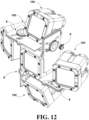
- the housing 1 is in a rectangular columnar shape.
- the housing 1 defines one connecting groove 10 on each of four side faces of the housing 1. Through the four connecting grooves 10, a connection between the housing 1 and other objects can be realized through the connectors 3, and jointing among a plurality of luminaires 100 can also be realized through the connectors 3. Thus, use is facilitated.
- the housing 1 may also be a cylinder, a triangular prism, or other polygonal prisms, and may also be a sphere, a polyhedron, or the like.
- the number of the connecting grooves 10 may be one, two or more. With two or more connecting grooves 10, the luminaire 100 can be connected to other objects, and jointing among a plurality of luminaires 100 can also be realized.
- the limit portion 11 is provided with a notch 110 that is communicated to the corresponding channel guide 12.
- a notch 110 Through the notch 110, a user can observe the internal condition of the channel guide 12 conveniently, and can clean foreign matters entering the channel guide 12, so that normal insertion matching between the connector 3 and the connecting groove 10 is facilitated.
- the connector 3 defines a positioning screw hole (not shown in the figure) therein.
- a positioning screw 34 is operable to be in threaded connection with the positioning screw hole to allow one end portion of the positioning screw 34 to be abutted against the bottom surface 10a of the connecting groove 10, such that the connector 3 is positioned in the connecting groove 10.
- the positioning screw 34 is tightened so that the end portion thereof is abutted against the bottom surface 10a of the connecting groove 10, and thus the connector 3 can be positioned in the connecting groove 10 and cannot slip off the connecting groove 10.
- the positioning screw 34 may be arranged at the position close to an end portion of the connector to prevent other objects blocking the positioning screw 34.
- the connector 3 defines a connecting screw hole 30 in a middle position of the along a length direction connector 3.
- the connecting screw hole 30 is located at a middle position between two connecting portions 31 disposed on the two opposite sides of the connector 3.
- the connecting screw hole 30 is disposed between the two connecting portions 30, so that an influence to matching between the connecting portions 31 and the channel guides 12 can be avoided.
- a plurality of connectors 3 may be arranged.
- the different connectors 3 can be used to connect the connecting grooves 10 on different side faces of the luminaire 100 to different objects.
- the connector is further provided with a fixing portion 32 on each of the two opposite sides of each connector 3.
- the fixing portion 32 and the connecting portion 31 cooperate to define a limit groove capable of accommodating the limit portion 11.
- a connection between the connector 3 and other objects can be facilitated through the fixing portions 32.
- the two fixing portions 32 may extend away from each other and are in a flat and straight shape.
- the two fixing portions 32 may extend from one side surface, away from the connecting portion 31, of the connector 3 to form a flat straight surface. As such, it further facilitates fixed connection between the connector 3 and other objects.
- the fixing portion 32 of the connector 3 may have the same shape and size as the connecting portion 31.
- the fixing portion 32 is operable to be inserted into and matched with the channel guide 12, which is equivalent to providing four connecting portions 31.
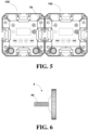
- the entire connector 3 may serve as a connecting pin 3a for connecting the housing 1 of the luminaire 100 to a housing of another luminaire 100. As such, it is possible to realize inserted connection with the connecting groove 10 of another luminaire 100.
- the connecting grooves 10 of the two luminaires 100 can be simultaneously connected by the connecting pin 3a, so that the two luminaires 100 are jointed together.
- a plurality of luminaires 100 can be joined together to form a modular structure.
- the luminaires 100 in different number as needed can be jointed to form a luminaire combination of different size and different lighting area.
- a dovetail groove is further arranged between the two connecting portions 31, which can reduce consumable of the connecting pin 3a.
- the connecting pin 3a is preferably a solid aluminum part, which is convenient to machine and shape and can ensure the connection strength.
- the luminaire 100 further includes a handwheel 4.
- the handwheel is provided with a handle screw 40 at a position of a central axis of the handwheel 4.
- the handle screw is operable to be in threaded connection with the connecting screw hole 30. Through threaded connection between the handle screw 40 and the connecting screw hole 30, other objects can be clamped between the handwheel 4 and the connector 3, so that fixed connection between the luminaire 100 and the other objects is realized.
- the disclosure further provides a luminaire combination, including two or more of the above-mentioned luminaires 100.
- the luminaire combination further includes at least one of a bracket 5, an adjusting plate 6, a hinge 7, and a cardan shaft 8.
- the bracket 5, the adjusting plate 6, the hinge 7, and the cardan shaft 8 each can be connected to the connector 3 of the luminaire 100.
- a plurality of luminaires 100 may be combined and jointed to form different shapes of luminaire combinations through one or multiple of the bracket 5, the hinge 7, the adjusting plate 6, and the cardan shaft 8.
- the bracket 5, the adjusting plate 6, the hinge 7, and the cardan shaft 8 will be respectively described below.
- the bracket 5 is a bent plate in an L shape and has two arms which serve as a base plate 51 and a connecting plate 52, respectively.
- the base plate 51 is in square shape.
- the connecting plate 52 is in a triangular shape.
- the connector 3 is disposed at the connecting plate 52.
- the connecting plate 52 defines a connecting hole (not shown in the figure) at a tip end, far away from the base plate 51, of the connecting plate 52.
- a handle screw 40 of the handwheel 4 penetrates the connecting hole to be in threaded connection with the connecting screw hole 30 of the connector 3.
- the handle screw 40 is screwed into the connecting screw hole 30 of the connector 3 to be used as a brake, so that the connector 3 is rotated to adjust an angle between the connector 3 and the bracket 5, to adjust a light projection angle of the luminaire 100.
- the connecting plate 52 is fixed and clamped between the handwheel 4 and the connector 3, so that fixed connection between the connector 3 and the bracket 5 is realized.
- the connecting plate 52 is triangular, which can avoid blocking the positioning screw 34.
- the connector 3 is inserted into the connecting groove 10, and the positioning screw is screwed on, so that fixed connection between the luminaire 100 and the bracket 5 can be realized.
- the base plate 51 is provided with a connecting block 53.
- the connecting block 53 is provided with a bracket screw hole 530.
- the bracket screw hole 530 has the same structure as the connecting screw hole, so that component universality is improved.
- the bracket screw hole 530 may be used to facilitate threaded connection with the cardan shaft 8 or other objects.
- the bracket 5 is generally used with the luminaire 100 individually, or serves as a coupler between the luminaire 100 or a luminaire combination and a holder, especially when the cardan shaft 8 is required.
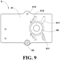
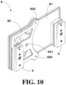
- the adjusting plate 6 is mainly used for a cross-shaped luminaire combination to achieve straight, divergent, or condensed light projection directions. As shown in FIG. 9 , FIG. 10 , and FIG. 11 , the adjusting plate 6 includes a first bearing plate 61, a second bearing plate 62, an adjusting handwheel 64, and a knurled screw 63. The first bearing plate 61 and the second bearing plate 62 are arranged in parallel. The first bearing plate 61 is in a rectangular shape. One connector 3 of one luminaire is disposed at one short edge of the first bearing plate 61. The second bearing plate 62 is arranged at the other short edge of the first bearing plate 61 and another connector 3 is disposed at the second bearing plate 62.
- the first bearing plate 61 defines a rotating through hole 610 at a long edge thereof.
- the second bearing plate 62 defines a rotating screw hole 620 at a position thereof corresponding to the rotating through hole 610.
- the knurled screw 63 penetrates the rotating through hole 610 to be in threaded connection with the rotating screw hole 620, so that a plate aligning hinge point is formed, i.e., a hinged point between the first bearing plate 61 and the second bearing plate 62 is formed.
- the knurled screw 63 serves as a pivot between the two plates, so that the first bearing plate 61 and the second bearing plate 62 may rotate relative to each other.
- the first bearing plate 61 defines a guide hole 611 in an arc-strip shape.
- the second bearing plate 62 defines an adjusting screw hole 621 at a position of the second bearing plate corresponding to the guide hole 611.
- An adjusting screw rod (not shown in the figure) is arranged at a position of a central axis of the adjusting handwheel 64.
- the adjusting screw rod penetrates the guide holes 611 to be in threaded connection with the adjusting screw hole 621.
- the first bearing plate 61 and the second bearing plate 62 may rotate relative to each other, and the adjusting screw rod moves along the guide holes 611.
- the adjusting handwheel 64 When the adjusting handwheel 64 is tightened by turning, the first bearing plate 61 is clamped between a wheel body and the second bearing plate 62, and positions of the first bearing plate 61 and the second bearing plate 62 are fixed.
- the adjusting handwheel 64 and the adjusting screw hole 621 are matched to form a brake, which can adjust the relative position between the first bearing plate 61 and the second bearing plate 62, so that the relative position between two connectors 3 can be adjusted, and further, the relative position between two luminaires 100 can be adjusted, thereby changing light projection angles of the two luminaires 100.
- both long edges of the first bearing plate 61 are provided with the rotating through holes 610, correspondingly, the second bearing plate 62 is provided with two rotating screw holes 620, and the first bearing plate 61 is provided with two guide holes 611.
- the knurled screw 63 may be detached from one of the rotating screw holes 620 and mounted into the other rotating screw hole 620, so that a rotating shaft between the first bearing plate 61 and the second bearing plate 62 may be changed to achieve adjustment of different angle directions between the two luminaires 100.
- first bearing plate 61 of the adjusting plate 6 is provided with angle mark slots 612, an opening angle can be accurately set, thereby facilitating adjustment to make angles, relative to the luminaire 100 at the center position, of the surrounding four luminaires 100 the same.
- four adjusting plates 6 and five luminaires 100 are used to form a luminaire combination.
- Four luminaires 100 may be adjustably arranged on four side faces of one luminaire 100, and by adjusting the first bearing plate 61 and the second bearing plate 62 to rotate relative to each other, overall light condensing or diverging of the luminaire combination formed of the five luminaires 100 can be achieved.
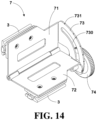
- the hinge 7 is used as a connection structural member, and can be used for adjustable connection between two luminaires 100. As shown in FIG. 14 and FIG. 15 , the hinge 7 includes a first hinge plate 71, a second hinge plate 72, and a hinge handwheel 74. The first hinge plate 71 and the second hinge plate 72 are hinged at their edges. One connector 3 of one luminaire 100 is disposed at the first hinge plate 71 and one connector 3 of another luminaire 100 is disposed at the second hinge plate 72. A length direction of each connector 3 is parallel to a pivot between the first hinge plate 71 and the second hinge plate 72. A brake plate 73 is fixed on the first hinge plate 71.
- the brake plate 73 is perpendicular to the pivot between the first hinge plate 71 and the second hinge plate 72, and defines a hinge hole 730 in an arc-strip shape.
- a portion, corresponding to the brake plate 73, of the second hinge plate 72 is bent and defines a hinge screw hole (not shown in the figure) therein.
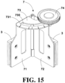
- a hinge screw rod (not shown in the figure) is arranged at a position of a central axis of the hinge handwheel 74. The hinge screw rod penetrates the hinge hole 730 to be in threaded connection with the hinge screw hole.
- the brake plate 73 When the hinge handwheel 74 is tightened by turning, the brake plate 73 is clamped between the hinge handwheel 74 and the second hinge plate 72, and positions of the first hinge plate 71, the brake plate 73, and the second hinge plate 72 are fixed.
- the hinge handwheel 74 and the hinge screw hole are matched to form a brake, which can adjust a relative angle between the two plates.
- the first hinge plate 71 and the second hinge plate 72 provided with the connectors 3, rotate around the pivot parallel to the plates, so that the opening degree of the two plates can be changed to adjust the relative position of the two luminaires 100.
- the brake plate 73 of the hinge 7 is provided with degree scale marks 731, which can achieve setting of the same angle. As shown in FIG.
- FIG. 16 with one luminaire 100 as the center, four hinges 7 and four luminaires are used on four sides of the luminaire 100 to form a cross-shaped luminaire combination. As shown in FIG. 17 , a plurality of luminaires 100, a plurality of hinges 7, brackets 5, and cardan shafts 8 are used to form a circular luminaire combination.
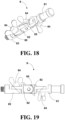
- the cardan shaft 8 is provided with three rotating shafts, which can flexibly connect the bracket 5 of the luminaire 100 or a luminaire combination to a support or a girder, or other objects.
- the cardan shaft 8 includes a fixed end 81, two intermediate parts 82, and a free end 83 which are sequentially rotationally connected.
- the fixed end 81 is used to be connected to other objects such as a support or a girder, and the free end 83 may be used to be connected to the connector 3 or the bracket 5.
- the fixed end 81 adopts an industrial standard plug, and is matched with a general standard clamp on the girder or the support.
- the free end 83 is provided with an external thread matched with the connecting screw hole 30 of the connector 3, so that a connection with the luminaire 100 is achieved.
- One wing handle screw 84 is arranged between the fixed end 81 and one intermediate part 82, one wing handle screw 84 is arranged between the two intermediate parts 82, and one wing handle screw 84 is arranged between the other intermediate part 82 and the free end 83.
- the three wing handle screws 84 may provide three rotating shafts, and at least one of the three rotating shafts is perpendicular to the other two rotating shafts. In this way, universal adjustment is achieved.
- the three wing handle screws 84 can be loosened or tightened manually easily, without the aid of tools.
- Positioning teeth 85 for preventing relative rotation are arranged between the fixed end 81 and one intermediate part 82 as well as between the two intermediate parts 82, and between the other intermediate 82 and the free end 83, which can prevent relative rotation after tightening.
- the connector 3 or the connecting pin 3a is matched with the connecting groove 10 of the housing 1 by inserting, the connector 3, is in matched connection with the bracket 5, the hinge 7, the adjusting plate 6, or the cardan shaft 8, and all four side faces of the housing 10 are provided with the connecting grooves 10. Aligning and combining of a plurality of luminaires can be achieved by using the connecting pins 3a, the hinges 7, and the adjusting plates 6. With the compact structure of the connecting pin 3a, the luminaires can be assembled with the maximum density of zero spacing.
- a compact linear combination can be formed; with the hinges 7, a cross-shaped or a circular combination can be formed; with the adjusting plates 6, a linear or a cross-shaped combination in a diverging direction can be formed. Aligning and fixing of a plurality of luminaires can be achieved through the brackets 5 and the cardan shafts 8.
- a plurality of luminaires 100 can be combined into a line, a cross shape or a circle as needed, and can be combined into various shapes of luminaire combinations. Thus, unlimited combination possibilities are provided for the luminaires 100.
- the handwheel 4, the adjusting handwheel 64, and the hinge handwheel 74 each can be matched with the corresponding screw hole to form a brake. Brakes can also be formed at positions of the wing handle screws 84 of the cardan shaft 8.
- light effects of the luminaire combination such as condensing, diverging, or in any other directions can be achieved by adjusting a vertical axis of each single luminaire, so that high flexibility in light direction and arrangement of the luminaire combination can be achieved.
- the luminaire combination can be connected to the support or the girder through a single connector or a plurality of joint points. Free alignment or any adjustment can be achieved through the brackets 5, the hinges 7, the adjusting plates 6, or the cardan shafts 8.
- the handwheel 4, the adjusting handwheel 4, and the hinge handwheel 74 may have the same shape and size, especially have the same external thread structure, which allow the three to form general components, thereby achieving exchange to facilitate mounting and using.
- the connecting accessories such as the brackets 5, the hinges 7, the adjusting plates 6 and the cardan shafts 8 each have simple structure, small size, and small space occupation, can avoid use of luminaire brackets with excessive space occupation, thereby facilitating forming of a compact spotlight array.
Landscapes
- Engineering & Computer Science (AREA)
- General Engineering & Computer Science (AREA)
- Fastening Of Light Sources Or Lamp Holders (AREA)
- Non-Portable Lighting Devices Or Systems Thereof (AREA)
Claims (15)
- Leuchtenkombination, umfassend mindestens zwei Leuchten (100) und eine Stellplatte (6), wobeijede der mindestens zwei Leuchten (100) ein Gehäuse (1) und ein Lichtquellenmodul (2) umfasst, das in dem Gehäuse (1) aufgenommen ist, wobeidas Gehäuse (1) darin eine Verbindungsnut (10) definiert, wobei die Verbindungsnut (10) in einer flachen Streifenform ist und sich aus einer Außenoberfläche des Gehäuses (1) erstreckt;die Leuchte (100) weiter einen Steckverbinder (3) in einer Streifenform umfasst, wobei ein Ende der Verbindungsnut (10) zum Einführen des Steckverbinders (3) geöffnet ist, die Verbindungsnut (10) mit einem Begrenzungsabschnitt (11) an jeder von zwei gegenüberliegenden Seitenwänden davon versehen ist, und ein Spalt zwischen jedem Begrenzungsabschnitt (11) und einer Bodenoberfläche(10a) der Verbindungsnut (10) eine Kanalführung (12) bildet; und der Steckverbinder (3) mit einem Verbindungsabschnitt (31) an jeder von zwei gegenüberliegenden Seiten davon versehen ist, und der Verbindungsabschnitt (31) betätigbar ist, um in die Kanalführung (12) entsprechend dem Verbindungsabschnitt (31) eingeführt, und darauf abgestimmt zu werden, sodass der Verbindungsabschnitt (31) in der Kanalführung (12) entsprechend dem Verbindungsabschnitt (31) über den Begrenzungsabschnitt (11) entsprechend dem Verbindungsabschnitt (31) begrenzt ist; unddie Stellplatte (6) eine erste Lagerplatte (61) in einer rechteckigen Form, eine zweite Lagerplatte (62), ein Stellhandrad (64) und eine Rändelschraube (63) umfasst, wobeidie erste Lagerplatte (61) und die zweite Lagerplatte (62) parallel angeordnet sind;ein Steckverbinder (3) einer Leuchte (100) an einer kurzen Kante der ersten Lagerplatte (61) vorgesehen ist, die zweite Lagerplatte (62) an der anderen kurzen Kante der ersten Lagerplatte (61) angeordnet ist, und ein anderer Steckverbinder (3) an der zweiten Lagerplatte (62) vorgesehen ist;die erste Lagerplatte (61) ein Drehdurchgangsloch (610) an einer langen Kante davon definiert, die zweite Lagerplatte (62) ein Drehschraubloch (620) in einer Position davon definiert, die dem Drehdurchgangsloch (610) entspricht, und die Rändelschraube (63) in das Drehdurchgangsloch (610) eindringt, um in Gewindeverbindung mit dem Drehschraubloch (620) zu sein, um einen Scharnierpunkt zwischen der ersten Lagerplatte (61) und der zweiten Lagerplatte (62) zu bilden; unddie erste Lagerplatte (61) ein Führungsloch (611) in einer Bogenstreifenform definiert, die zweite Lagerplatte (62) ein Stellschraubloch (621) in einer Position der zweiten Lagerplatte (62) definiert, die dem Führungsloch (611) entspricht, eine Stellgewindestange in einer Position einer Mittelachse des Stellhandrades (64) angeordnet ist, und die Stellgewindestange in die Führungslöcher (611) eindringt, um in Gewindeverbindung mit dem Stellschraubloch (621) zu sein.
- Leuchtenkombination nach Anspruch 1, wobei das Gehäuse (1) in Säulenform ist, eine Mittelachse des Gehäuses (1) mit einer Lichtausgangsrichtung des Lichtquellenmoduls (2) übereinstimmt, und eine Längsrichtung der Verbindungsnut (10) parallel zur Mittelachse des Gehäuses (1) ist.
- Leuchtenkombination nach Anspruch 2, wobei das Gehäuse (1) in einer rechteckigen Säulenform ist, und eine Verbindungsnut (10) an jeder von vier Seitenflächen des Gehäuses (1) definiert.
- Leuchtenkombination nach Anspruch 1, wobeider Steckverbinder (3) darin ein Positionierschraubloch definiert; undeine Positionierschraube (34) betätigbar ist, um in Gewindeverbindung mit dem Positionierschraubloch zu sein, um zu ermöglichen, dass ein Endabschnitt der Positionierschraube (34) an der Bodenoberfläche (10a) der Verbindungsnut (10) anliegt, sodass der Steckverbinder (3) in der Verbindungsnut (10) positioniert ist.
- Leuchtenkombination nach Anspruch 1, wobei der Steckverbinder (3) ein Verbindungsschraubloch (30) in einer mittleren Position entlang einer Längsrichtung des Steckverbinders (3) definiert, und sich das Verbindungsschraubloch (30) in einer mittleren Position zwischen zwei Verbindungsabschnitten (31) befindet, die an den zwei gegenüberliegenden Seiten des Steckverbinders (3) vorgesehen sind.
- Leuchtenkombination nach Anspruch 5, wobei die Leuchte (100) weiter ein Handrad (4) umfasst, wobei das Handrad (4) mit einer Griffschraube (40) in einer Position einer Mittelachse des Handrades (4) bereitgestellt ist, und die Griffschraube (40) betätigbar ist, um in Gewindeverbindung mit dem Verbindungsschraubloch (30) zu sein.
- Leuchtenkombination nach Anspruch 1, wobei der Steckverbinder (3) weiter mit einem Fixierabschnitt (32) an jeder der beiden gegenüberliegenden Seiten des Steckverbinders (3) bereitgestellt ist, und der Fixierabschnitt (32) und der Verbindungsabschnitt (31) zusammenwirken, um eine Begrenzungsnut zu definieren, die imstande ist, den Begrenzungsabschnitt (11) aufzunehmen.
- Leuchtenkombination nach Anspruch 7, wobeisich die beiden Fixierabschnitte (32) voneinander weg erstrecken, und in einer flachen und geraden Form sind, und sich aus einer Seitenoberfläche des Steckverbinders (3), von dem Verbindungsabschnitt (31) weg, erstrecken, um eine flache gerade Oberfläche zu bilden; oderder Fixierabschnitt (32) und der Verbindungsabschnitt (31) dieselbe Form und Größe aufweisen, der Fixierabschnitt (32) betätigbar ist, um in die Kanalführung (12) eingeführt, und darauf abgestimmt zu werden, sodass der Steckverbinder (3) als Verbindungsstift zum Verbinden des Gehäuses (1) der Leuchte (100) mit einem Gehäuse (1) einer anderen Leuchte (100) dient.
- Leuchtenkombination nach Anspruch 1, weiter umfassend mindestens eines von:einer Halterung (5), wobeidie Halterung (5) eine gebogene Platte in einer L-Form ist und zwei Arme aufweist, die jeweils als Grundplatte (51) in einer Quadratform und Verbindungsplatte (52) in einer dreieckigen Form dienen;der Steckverbinder (3) der Leuchte (100) an der Verbindungsplatte (52) vorgesehen ist;die Verbindungsplatte (52) ein Verbindungsloch an einem Spitzenende der Verbindungsplatte (52), von der Grundplatte (51) weg, definiert; undeine Griffschraube (40) eines Handrades (4) in das Verbindungsloch eindringt, um in Gewindeverbindung mit dem Verbindungsschraubloch (30) des Steckverbinders (3) zu sein; oderein Scharnier (7), wobei:das Scharnier (7) eine erste Scharnierplatte (71), eine zweite Scharnierplatte (72) und ein Scharnierhandrad (74) umfasst, wobei die erste Scharnierplatte (71) und die zweite Scharnierplatte (72) an ihren Kanten angeschlagen sind;ein Steckverbinder (3) von einer Leuchte (100) an der ersten Scharnierplatte (71) vorgesehen ist und ein Steckverbinder (3) einer anderen Leuchte (100) an der zweiten Scharnierplatte (72) vorgesehen ist, und eine Längsrichtung eines jeden Steckverbinders (3) parallel zu einem Drehpunkt zwischen der ersten Scharnierplatte (71) und der zweiten Scharnierplatte (72) ist;eine Bremsplatte (73) an der ersten Scharnierplatte (71) fixiert ist, wobei die Bremsplatte (73) senkrecht zum Drehpunkt zwischen der ersten Scharnierplatte (71) und der zweiten Scharnierplatte (72) ist, und ein Scharnierloch (730) in einer Bogenbandform definiert, und ein Abschnitt der zweiten Scharnierplatte (72) entsprechend dem Scharnierloch (730) gebogen ist, und darin ein Scharnierschraubloch definiert; undeine Scharniergewindestange in einer Position einer Mittelachse des Scharnierhandrades (74) angeordnet ist, wobei die Scharniergewindestange in das Scharnierloch (730) eindringt, um in Gewindeverbindung mit dem Scharnierschraubloch zu sein; odereine Kardanwelle (8), wobei:die Kardanwelle (8) ein feststehendes Ende (81), zwei Zwischenteile (82) und ein freies Ende (83) umfasst, die sequenziell drehend verbunden sind; undeine Flügelgriffschraube (84) zwischen dem feststehenden Ende (81) und einem Zwischenteil (82) angeordnet ist, eine Flügelgriffschraube (84) zwischen den beiden Zwischenteilen (82) angeordnet ist, eine Flügelgriffschraube (84) zwischen dem anderen Zwischenteil (82) und dem freien Ende (83) angeordnet ist, und die drei Flügelgriffschrauben (84) drei Drehwellen bereitstellen, und mindestens eine der drei Drehwellen senkrecht zu den anderen beiden Drehwellen ist.
- Leuchtenkombination, umfassend mindestens zwei Leuchten (100) und mindestens eines von einem Scharnier (7) oder einer Kardanwelle (8), wobeijede der mindestens zwei Leuchten (100) ein Gehäuse (1) und ein Lichtquellenmodul (2) umfasst, das in dem Gehäuse (1) aufgenommen ist, wobeidas Gehäuse (1) darin eine Verbindungsnut (10) definiert, wobei die Verbindungsnut (10) in einer flachen Streifenform ist und sich aus einer Außenoberfläche des Gehäuses (1) erstreckt;die Leuchte (100) weiter einen Steckverbinder (3) in einer Streifenform umfasst, wobei ein Ende der Verbindungsnut (10) zum Einführen des Steckverbinders (3) geöffnet ist, die Verbindungsnut (10) mit einem Begrenzungsabschnitt (11) an jeder von zwei gegenüberliegenden Seitenwänden davon versehen ist, und ein Spalt zwischen jedem Begrenzungsabschnitt (11) und einer Bodenoberfläche (10a) der Verbindungsnut (10) eine Kanalführung (12) bildet; und der Steckverbinder (3) mit einem Verbindungsabschnitt (31) an jeder von zwei gegenüberliegenden Seiten davon versehen ist, und der Verbindungsabschnitt (31) betätigbar ist, um in die Kanalführung (12) entsprechend dem Verbindungsabschnitt (31) eingeführt, und darauf abgestimmt zu werden, sodass der Verbindungsabschnitt (31) in der Kanalführung (12) entsprechend dem Verbindungsabschnitt (31) über den Begrenzungsabschnitt (11) entsprechend dem Verbindungsabschnitt (31) begrenzt ist; unddas Scharnier (7) eine erste Scharnierplatte (71), eine zweite Scharnierplatte (72) und ein Scharnierhandrad (74) umfasst, wobei die erste Scharnierplatte (71) und die zweite Scharnierplatte (72) an ihren Kanten angeschlagen sind, wobeiein Steckverbinder (3) einer Leuchte (100) an der ersten Scharnierplatte (71) vorgesehen ist, und ein Steckverbinder (3) einer anderen Leuchte (100) an der zweiten Scharnierplatte (72) vorgesehen ist, und eine Längsrichtung eines jeden Steckverbinders (3) parallel zu einem Drehpunkt zwischen der ersten Scharnierplatte (71) und der zweiten Scharnierplatte (72) ist;eine Bremsplatte (73) an der ersten Scharnierplatte (71) fixiert ist, wobei die Bremsplatte (73) senkrecht zum Drehpunkt zwischen der ersten Scharnierplatte (71) und der zweiten Scharnierplatte (72) ist, und ein Scharnierloch (730) in einer Bogenbandform definiert, und ein Abschnitt der zweiten Scharnierplatte (72) entsprechend dem Scharnierloch (730) gebogen ist, und darin ein Scharnierschraubloch definiert; undeine Scharniergewindestange in einer Position einer Mittelachse des Scharnierhandrades (74) angeordnet ist, wobei die Scharniergewindestange in das Scharnierloch (730) eindringt, um in Gewindeverbindung mit dem Scharnierschraubloch zu sein; unddie Kardanwelle (8) ein feststehendes Ende (81), zwei Zwischenteile (82) und ein freies Ende (83) umfasst, die sequenziell drehend verbunden sind; undeine Flügelgriffschraube (84) zwischen dem feststehenden Ende (81) und einem Zwischenteil (82) angeordnet ist, eine Flügelgriffschraube (84) zwischen den beiden Zwischenteilen (82) angeordnet ist, eine Flügelgriffschraube (84) zwischen dem anderen Zwischenteil (82) und dem freien Ende (83) angeordnet ist, und die drei Flügelgriffschrauben (84) drei Drehwellen bereitstellen, und mindestens eine der drei Drehwellen senkrecht zu den anderen beiden Drehwellen ist.
- Leuchtenkombination nach Anspruch 10, wobei das Gehäuse (1) in Säulenform ist, eine Mittelachse des Gehäuses (1) mit einer Lichtausgangsrichtung des Lichtquellenmoduls (2) übereinstimmt, und eine Längsrichtung der Verbindungsnut (10) parallel zur Mittelachse des Gehäuses (1) ist.
- Leuchtenkombination nach Anspruch 11, wobei das Gehäuse (1) in einer rechteckigen Säulenform ist, und eine Verbindungsnut (10) an jeder von vier Seitenflächen des Gehäuses (1) definiert.
- Leuchtenkombination nach Anspruch 10, wobei der Steckverbinder (3) darin ein Positionierschraubloch definiert; und
eine Positionierschraube (34) betätigbar ist, um in Gewindeverbindung mit dem Positionierschraubloch zu sein, um zu ermöglichen, dass ein Endabschnitt der Positionierschraube (34) an der Bodenoberfläche (10a) der Verbindungsnut (10) anliegt, sodass der Steckverbinder (3) in der Verbindungsnut (10) positioniert ist. - Leuchtenkombination nach Anspruch 10, wobei der Steckverbinder (3) ein Verbindungsschraubloch (30) in einer mittleren Position entlang einer Längsrichtung des Steckverbinders (3) definiert, und sich das Verbindungsschraubloch (30) in einer mittleren Position zwischen zwei Verbindungsabschnitten (31) befindet, die an den beiden gegenüberliegenden Seiten des Steckverbinders (3) vorgesehen sind.
- Leuchtenkombination nach Anspruch 14, wobei die Leuchte (100) weiter ein Handrad (4) umfasst, wobei das Handrad (4) mit einer Griffschraube (40) in einer Position einer zentralen Achse des Handrades (4) bereitgestellt ist, und die Griffschraube (40) betätigbar ist, um in Gewindeverbindung mit dem Verbindungsschraubloch (30) zu sein.
Applications Claiming Priority (1)
| Application Number | Priority Date | Filing Date | Title |
|---|---|---|---|
| CN202120980786.3U CN215336168U (zh) | 2021-05-08 | 2021-05-08 | 灯具及灯组 |
Publications (3)
| Publication Number | Publication Date |
|---|---|
| EP4086504A1 EP4086504A1 (de) | 2022-11-09 |
| EP4086504C0 EP4086504C0 (de) | 2023-11-22 |
| EP4086504B1 true EP4086504B1 (de) | 2023-11-22 |
Family
ID=77168103
Family Applications (1)
| Application Number | Title | Priority Date | Filing Date |
|---|---|---|---|
| EP21189097.5A Active EP4086504B1 (de) | 2021-05-08 | 2021-08-02 | Leuchte und leuchtenkombination |
Country Status (3)
| Country | Link |
|---|---|
| US (1) | US11592148B2 (de) |
| EP (1) | EP4086504B1 (de) |
| CN (1) | CN215336168U (de) |
Families Citing this family (1)
| Publication number | Priority date | Publication date | Assignee | Title |
|---|---|---|---|---|
| USD1063865S1 (en) * | 2022-04-15 | 2025-02-25 | Astera Manufacturing Limited | Connector plate |
Family Cites Families (12)
| Publication number | Priority date | Publication date | Assignee | Title |
|---|---|---|---|---|
| US4447859A (en) * | 1982-11-26 | 1984-05-08 | Inverse Square Systems Incorporated | Modular flash system |
| US4918576A (en) * | 1988-11-18 | 1990-04-17 | Farrall Instruments, Inc. | Photographic flash lighting unit |
| DE20311557U1 (de) * | 2003-07-26 | 2003-10-16 | Neuhorst Paul Heinrich | Leuchte für Beleuchtungszwecke |
| DE102006018668B4 (de) * | 2006-04-21 | 2013-04-11 | Osram Gmbh | Modulares Beleuchtungssystem und Beleuchtungsanordnung |
| KR100944521B1 (ko) * | 2007-10-29 | 2010-03-03 | 주식회사 웰라이트 | 가로등용 조명장치 |
| US20120163004A1 (en) * | 2010-12-22 | 2012-06-28 | Jenn Feng New Energy Co., Ltd. | Angle adjustable lamp |
| WO2013063247A1 (en) * | 2011-10-26 | 2013-05-02 | 0Energy Lighting, Inc. | Interlocking lighting fixture |
| US9857037B1 (en) * | 2016-06-28 | 2018-01-02 | Glt Corporation | Assembling structure for LED luminaire |
| US20180087755A1 (en) * | 2016-09-29 | 2018-03-29 | Biological Innovation & Optimization Systems, LLC | Adjustable led grow light fixtures |
| CN108518620A (zh) * | 2018-06-07 | 2018-09-11 | 苏州欧普照明有限公司 | 一种灯具以及灯具组件 |
| US10995941B2 (en) * | 2018-12-17 | 2021-05-04 | MaxLite, Inc. | Adjustable, modular flood light fixture |
| US11085594B2 (en) * | 2019-12-12 | 2021-08-10 | XAL Inc. | Modular lighting system and interconnectable lighting cells |
-
2021
- 2021-05-08 CN CN202120980786.3U patent/CN215336168U/zh active Active
- 2021-08-02 EP EP21189097.5A patent/EP4086504B1/de active Active
- 2021-08-05 US US17/395,206 patent/US11592148B2/en active Active
Also Published As
| Publication number | Publication date |
|---|---|
| EP4086504C0 (de) | 2023-11-22 |
| US20220356997A1 (en) | 2022-11-10 |
| EP4086504A1 (de) | 2022-11-09 |
| US11592148B2 (en) | 2023-02-28 |
| CN215336168U (zh) | 2021-12-28 |
Similar Documents
| Publication | Publication Date | Title |
|---|---|---|
| KR100388767B1 (ko) | 교환가능한어댑터를구비한절삭공구조립체 | |
| US9381621B2 (en) | Tooling fixture and system | |
| US8469536B2 (en) | Recessed light housing with rotatable aperture | |
| KR20010012089A (ko) | 조정가능한 리드각 챔퍼링공구 홀더 | |
| EP4086504B1 (de) | Leuchte und leuchtenkombination | |
| US5918868A (en) | Universal modular fixturing systems | |
| CN104602844A (zh) | 可调节销式夹具 | |
| CN103453487A (zh) | 一种调节转动装置及具有该调节转动装置的灯具 | |
| US5260860A (en) | Expanding tenon clamp | |
| US20140026405A1 (en) | Auxiliary fitting jig | |
| CN111399168A (zh) | 一种空间直角转折联用调节架 | |
| CN217382332U (zh) | 支架、摄像系统及照明系统 | |
| CN217584250U (zh) | 一种工作灯 | |
| JP2002191442A (ja) | 各種天板に対応可能な脚部を有するテーブル | |
| CN222711505U (zh) | 钛棒夹具和钛棒加工系统 | |
| CN223105972U (zh) | 可多向调节的台灯 | |
| KR20000000222U (ko) | 공작물의 고정장치 | |
| CN217581037U (zh) | 一种转轴式金属线条安装机构 | |
| CN217316984U (zh) | 一种组合式定位工装夹具 | |
| CN223375708U (zh) | 一种灯支架 | |
| CN112077756A (zh) | 一种电气机械设备生产夹紧结构 | |
| EP4368064A1 (de) | Tragende metallstruktur für möbelelement | |
| CN212977488U (zh) | 车架治具 | |
| CN217830614U (zh) | 一种反光镜上胶夹具工装 | |
| CN2394239Y (zh) | 可架设于多款灯架上的可调式放大镜持用架 |
Legal Events
| Date | Code | Title | Description |
|---|---|---|---|
| PUAI | Public reference made under article 153(3) epc to a published international application that has entered the european phase |
Free format text: ORIGINAL CODE: 0009012 |
|
| STAA | Information on the status of an ep patent application or granted ep patent |
Free format text: STATUS: REQUEST FOR EXAMINATION WAS MADE |
|
| 17P | Request for examination filed |
Effective date: 20210802 |
|
| AK | Designated contracting states |
Kind code of ref document: A1 Designated state(s): AL AT BE BG CH CY CZ DE DK EE ES FI FR GB GR HR HU IE IS IT LI LT LU LV MC MK MT NL NO PL PT RO RS SE SI SK SM TR |
|
| RIC1 | Information provided on ipc code assigned before grant |
Ipc: F21W 131/406 20060101ALN20230622BHEP Ipc: F21V 21/30 20060101ALI20230622BHEP Ipc: F21V 21/005 20060101ALI20230622BHEP Ipc: F21S 2/00 20160101AFI20230622BHEP |
|
| GRAP | Despatch of communication of intention to grant a patent |
Free format text: ORIGINAL CODE: EPIDOSNIGR1 |
|
| STAA | Information on the status of an ep patent application or granted ep patent |
Free format text: STATUS: GRANT OF PATENT IS INTENDED |
|
| RIC1 | Information provided on ipc code assigned before grant |
Ipc: F21W 131/406 20060101ALN20230622BHEP Ipc: F21V 21/30 20060101ALI20230622BHEP Ipc: F21V 21/005 20060101ALI20230622BHEP Ipc: F21S 2/00 20160101AFI20230622BHEP |
|
| RIC1 | Information provided on ipc code assigned before grant |
Ipc: F21W 131/406 20060101ALN20230717BHEP Ipc: F21V 21/30 20060101ALI20230717BHEP Ipc: F21V 21/005 20060101ALI20230717BHEP Ipc: F21S 2/00 20160101AFI20230717BHEP |
|
| INTG | Intention to grant announced |
Effective date: 20230801 |
|
| GRAS | Grant fee paid |
Free format text: ORIGINAL CODE: EPIDOSNIGR3 |
|
| GRAA | (expected) grant |
Free format text: ORIGINAL CODE: 0009210 |
|
| STAA | Information on the status of an ep patent application or granted ep patent |
Free format text: STATUS: THE PATENT HAS BEEN GRANTED |
|
| AK | Designated contracting states |
Kind code of ref document: B1 Designated state(s): AL AT BE BG CH CY CZ DE DK EE ES FI FR GB GR HR HU IE IS IT LI LT LU LV MC MK MT NL NO PL PT RO RS SE SI SK SM TR |
|
| REG | Reference to a national code |
Ref country code: GB Ref legal event code: FG4D |
|
| REG | Reference to a national code |
Ref country code: CH Ref legal event code: EP |
|
| REG | Reference to a national code |
Ref country code: DE Ref legal event code: R096 Ref document number: 602021007006 Country of ref document: DE |
|
| REG | Reference to a national code |
Ref country code: IE Ref legal event code: FG4D |
|
| U01 | Request for unitary effect filed |
Effective date: 20231122 |
|
| U07 | Unitary effect registered |
Designated state(s): AT BE BG DE DK EE FI FR IT LT LU LV MT NL PT SE SI Effective date: 20231127 |
|
| PG25 | Lapsed in a contracting state [announced via postgrant information from national office to epo] |
Ref country code: GR Free format text: LAPSE BECAUSE OF FAILURE TO SUBMIT A TRANSLATION OF THE DESCRIPTION OR TO PAY THE FEE WITHIN THE PRESCRIBED TIME-LIMIT Effective date: 20240223 |
|
| PG25 | Lapsed in a contracting state [announced via postgrant information from national office to epo] |
Ref country code: IS Free format text: LAPSE BECAUSE OF FAILURE TO SUBMIT A TRANSLATION OF THE DESCRIPTION OR TO PAY THE FEE WITHIN THE PRESCRIBED TIME-LIMIT Effective date: 20240322 |
|
| PG25 | Lapsed in a contracting state [announced via postgrant information from national office to epo] |
Ref country code: ES Free format text: LAPSE BECAUSE OF FAILURE TO SUBMIT A TRANSLATION OF THE DESCRIPTION OR TO PAY THE FEE WITHIN THE PRESCRIBED TIME-LIMIT Effective date: 20231122 |
|
| PG25 | Lapsed in a contracting state [announced via postgrant information from national office to epo] |
Ref country code: IS Free format text: LAPSE BECAUSE OF FAILURE TO SUBMIT A TRANSLATION OF THE DESCRIPTION OR TO PAY THE FEE WITHIN THE PRESCRIBED TIME-LIMIT Effective date: 20240322 Ref country code: GR Free format text: LAPSE BECAUSE OF FAILURE TO SUBMIT A TRANSLATION OF THE DESCRIPTION OR TO PAY THE FEE WITHIN THE PRESCRIBED TIME-LIMIT Effective date: 20240223 Ref country code: ES Free format text: LAPSE BECAUSE OF FAILURE TO SUBMIT A TRANSLATION OF THE DESCRIPTION OR TO PAY THE FEE WITHIN THE PRESCRIBED TIME-LIMIT Effective date: 20231122 |
|
| PG25 | Lapsed in a contracting state [announced via postgrant information from national office to epo] |
Ref country code: RS Free format text: LAPSE BECAUSE OF FAILURE TO SUBMIT A TRANSLATION OF THE DESCRIPTION OR TO PAY THE FEE WITHIN THE PRESCRIBED TIME-LIMIT Effective date: 20231122 Ref country code: PL Free format text: LAPSE BECAUSE OF FAILURE TO SUBMIT A TRANSLATION OF THE DESCRIPTION OR TO PAY THE FEE WITHIN THE PRESCRIBED TIME-LIMIT Effective date: 20231122 Ref country code: NO Free format text: LAPSE BECAUSE OF FAILURE TO SUBMIT A TRANSLATION OF THE DESCRIPTION OR TO PAY THE FEE WITHIN THE PRESCRIBED TIME-LIMIT Effective date: 20240222 Ref country code: HR Free format text: LAPSE BECAUSE OF FAILURE TO SUBMIT A TRANSLATION OF THE DESCRIPTION OR TO PAY THE FEE WITHIN THE PRESCRIBED TIME-LIMIT Effective date: 20231122 |
|
| PG25 | Lapsed in a contracting state [announced via postgrant information from national office to epo] |
Ref country code: CZ Free format text: LAPSE BECAUSE OF FAILURE TO SUBMIT A TRANSLATION OF THE DESCRIPTION OR TO PAY THE FEE WITHIN THE PRESCRIBED TIME-LIMIT Effective date: 20231122 |
|
| PG25 | Lapsed in a contracting state [announced via postgrant information from national office to epo] |
Ref country code: SK Free format text: LAPSE BECAUSE OF FAILURE TO SUBMIT A TRANSLATION OF THE DESCRIPTION OR TO PAY THE FEE WITHIN THE PRESCRIBED TIME-LIMIT Effective date: 20231122 |
|
| PG25 | Lapsed in a contracting state [announced via postgrant information from national office to epo] |
Ref country code: SM Free format text: LAPSE BECAUSE OF FAILURE TO SUBMIT A TRANSLATION OF THE DESCRIPTION OR TO PAY THE FEE WITHIN THE PRESCRIBED TIME-LIMIT Effective date: 20231122 Ref country code: SK Free format text: LAPSE BECAUSE OF FAILURE TO SUBMIT A TRANSLATION OF THE DESCRIPTION OR TO PAY THE FEE WITHIN THE PRESCRIBED TIME-LIMIT Effective date: 20231122 Ref country code: RO Free format text: LAPSE BECAUSE OF FAILURE TO SUBMIT A TRANSLATION OF THE DESCRIPTION OR TO PAY THE FEE WITHIN THE PRESCRIBED TIME-LIMIT Effective date: 20231122 Ref country code: CZ Free format text: LAPSE BECAUSE OF FAILURE TO SUBMIT A TRANSLATION OF THE DESCRIPTION OR TO PAY THE FEE WITHIN THE PRESCRIBED TIME-LIMIT Effective date: 20231122 |
|
| REG | Reference to a national code |
Ref country code: DE Ref legal event code: R097 Ref document number: 602021007006 Country of ref document: DE |
|
| U20 | Renewal fee for the european patent with unitary effect paid |
Year of fee payment: 4 Effective date: 20240822 |
|
| PLBE | No opposition filed within time limit |
Free format text: ORIGINAL CODE: 0009261 |
|
| STAA | Information on the status of an ep patent application or granted ep patent |
Free format text: STATUS: NO OPPOSITION FILED WITHIN TIME LIMIT |
|
| 26N | No opposition filed |
Effective date: 20240823 |
|
| REG | Reference to a national code |
Ref country code: CH Ref legal event code: PL |
|
| PG25 | Lapsed in a contracting state [announced via postgrant information from national office to epo] |
Ref country code: CH Free format text: LAPSE BECAUSE OF NON-PAYMENT OF DUE FEES Effective date: 20240831 Ref country code: MC Free format text: LAPSE BECAUSE OF FAILURE TO SUBMIT A TRANSLATION OF THE DESCRIPTION OR TO PAY THE FEE WITHIN THE PRESCRIBED TIME-LIMIT Effective date: 20231122 |
|
| PG25 | Lapsed in a contracting state [announced via postgrant information from national office to epo] |
Ref country code: IE Free format text: LAPSE BECAUSE OF NON-PAYMENT OF DUE FEES Effective date: 20240802 |
|
| U20 | Renewal fee for the european patent with unitary effect paid |
Year of fee payment: 5 Effective date: 20250828 |
|
| PGFP | Annual fee paid to national office [announced via postgrant information from national office to epo] |
Ref country code: GB Payment date: 20250826 Year of fee payment: 5 |
|
| U1N | Appointed representative for the unitary patent procedure changed after the registration of the unitary effect |
Representative=s name: SANTARELLI; FR |