EP4086491A1 - Valve assembly - Google Patents
Valve assembly Download PDFInfo
- Publication number
- EP4086491A1 EP4086491A1 EP22171236.7A EP22171236A EP4086491A1 EP 4086491 A1 EP4086491 A1 EP 4086491A1 EP 22171236 A EP22171236 A EP 22171236A EP 4086491 A1 EP4086491 A1 EP 4086491A1
- Authority
- EP
- European Patent Office
- Prior art keywords
- valve
- valve arrangement
- pressure
- spring
- outlet
- Prior art date
- Legal status (The legal status is an assumption and is not a legal conclusion. Google has not performed a legal analysis and makes no representation as to the accuracy of the status listed.)
- Pending
Links
Images


Classifications
-
- B—PERFORMING OPERATIONS; TRANSPORTING
- B05—SPRAYING OR ATOMISING IN GENERAL; APPLYING FLUENT MATERIALS TO SURFACES, IN GENERAL
- B05B—SPRAYING APPARATUS; ATOMISING APPARATUS; NOZZLES
- B05B1/00—Nozzles, spray heads or other outlets, with or without auxiliary devices such as valves, heating means
- B05B1/30—Nozzles, spray heads or other outlets, with or without auxiliary devices such as valves, heating means designed to control volume of flow, e.g. with adjustable passages
- B05B1/3093—Recirculation valves, i.e. the valve element opens a passage to the nozzle and simultaneously closes at least partially a return passage the feeding means
-
- B—PERFORMING OPERATIONS; TRANSPORTING
- B05—SPRAYING OR ATOMISING IN GENERAL; APPLYING FLUENT MATERIALS TO SURFACES, IN GENERAL
- B05B—SPRAYING APPARATUS; ATOMISING APPARATUS; NOZZLES
- B05B1/00—Nozzles, spray heads or other outlets, with or without auxiliary devices such as valves, heating means
- B05B1/30—Nozzles, spray heads or other outlets, with or without auxiliary devices such as valves, heating means designed to control volume of flow, e.g. with adjustable passages
- B05B1/3006—Nozzles, spray heads or other outlets, with or without auxiliary devices such as valves, heating means designed to control volume of flow, e.g. with adjustable passages the controlling element being actuated by the pressure of the fluid to be sprayed
-
- B—PERFORMING OPERATIONS; TRANSPORTING
- B05—SPRAYING OR ATOMISING IN GENERAL; APPLYING FLUENT MATERIALS TO SURFACES, IN GENERAL
- B05B—SPRAYING APPARATUS; ATOMISING APPARATUS; NOZZLES
- B05B12/00—Arrangements for controlling delivery; Arrangements for controlling the spray area
- B05B12/08—Arrangements for controlling delivery; Arrangements for controlling the spray area responsive to condition of liquid or other fluent material to be discharged, of ambient medium or of target ; responsive to condition of spray devices or of supply means, e.g. pipes, pumps or their drive means
- B05B12/085—Arrangements for controlling delivery; Arrangements for controlling the spray area responsive to condition of liquid or other fluent material to be discharged, of ambient medium or of target ; responsive to condition of spray devices or of supply means, e.g. pipes, pumps or their drive means responsive to flow or pressure of liquid or other fluent material to be discharged
- B05B12/087—Flow or presssure regulators, i.e. non-electric unitary devices comprising a sensing element, e.g. a piston or a membrane, and a controlling element, e.g. a valve
-
- F—MECHANICAL ENGINEERING; LIGHTING; HEATING; WEAPONS; BLASTING
- F16—ENGINEERING ELEMENTS AND UNITS; GENERAL MEASURES FOR PRODUCING AND MAINTAINING EFFECTIVE FUNCTIONING OF MACHINES OR INSTALLATIONS; THERMAL INSULATION IN GENERAL
- F16K—VALVES; TAPS; COCKS; ACTUATING-FLOATS; DEVICES FOR VENTING OR AERATING
- F16K17/00—Safety valves; Equalising valves, e.g. pressure relief valves
- F16K17/02—Safety valves; Equalising valves, e.g. pressure relief valves opening on surplus pressure on one side; closing on insufficient pressure on one side
- F16K17/04—Safety valves; Equalising valves, e.g. pressure relief valves opening on surplus pressure on one side; closing on insufficient pressure on one side spring-loaded
- F16K17/0406—Safety valves; Equalising valves, e.g. pressure relief valves opening on surplus pressure on one side; closing on insufficient pressure on one side spring-loaded in the form of balls
-
- F—MECHANICAL ENGINEERING; LIGHTING; HEATING; WEAPONS; BLASTING
- F16—ENGINEERING ELEMENTS AND UNITS; GENERAL MEASURES FOR PRODUCING AND MAINTAINING EFFECTIVE FUNCTIONING OF MACHINES OR INSTALLATIONS; THERMAL INSULATION IN GENERAL
- F16K—VALVES; TAPS; COCKS; ACTUATING-FLOATS; DEVICES FOR VENTING OR AERATING
- F16K17/00—Safety valves; Equalising valves, e.g. pressure relief valves
- F16K17/02—Safety valves; Equalising valves, e.g. pressure relief valves opening on surplus pressure on one side; closing on insufficient pressure on one side
- F16K17/04—Safety valves; Equalising valves, e.g. pressure relief valves opening on surplus pressure on one side; closing on insufficient pressure on one side spring-loaded
- F16K17/0446—Safety valves; Equalising valves, e.g. pressure relief valves opening on surplus pressure on one side; closing on insufficient pressure on one side spring-loaded with an obturating member having at least a component of their opening and closing motion not perpendicular to the closing faces
- F16K17/046—Safety valves; Equalising valves, e.g. pressure relief valves opening on surplus pressure on one side; closing on insufficient pressure on one side spring-loaded with an obturating member having at least a component of their opening and closing motion not perpendicular to the closing faces the valve being of the gate valve type or the sliding valve type
-
- F—MECHANICAL ENGINEERING; LIGHTING; HEATING; WEAPONS; BLASTING
- F16—ENGINEERING ELEMENTS AND UNITS; GENERAL MEASURES FOR PRODUCING AND MAINTAINING EFFECTIVE FUNCTIONING OF MACHINES OR INSTALLATIONS; THERMAL INSULATION IN GENERAL
- F16K—VALVES; TAPS; COCKS; ACTUATING-FLOATS; DEVICES FOR VENTING OR AERATING
- F16K17/00—Safety valves; Equalising valves, e.g. pressure relief valves
- F16K17/02—Safety valves; Equalising valves, e.g. pressure relief valves opening on surplus pressure on one side; closing on insufficient pressure on one side
- F16K17/04—Safety valves; Equalising valves, e.g. pressure relief valves opening on surplus pressure on one side; closing on insufficient pressure on one side spring-loaded
- F16K17/06—Safety valves; Equalising valves, e.g. pressure relief valves opening on surplus pressure on one side; closing on insufficient pressure on one side spring-loaded with special arrangements for adjusting the opening pressure
Definitions
- the present invention relates to a valve arrangement according to the preamble of claim 1 and a high-pressure cleaning device.
- the present invention relates to safety valve assemblies and circulation valve assemblies.
- the valve arrangement according to the invention can also be used for other applications and can be advantageous.
- Safety valves are used to protect a hydraulic system against unwanted overpressure. They are therefore also referred to as pressure relief valves or pressure relief valves. These terms are therefore preferably to be understood as synonymous below.
- Safety valve arrangements are used in particular in piston pumps, such as a high-pressure cleaning device or water jet cleaning device.
- the opening and closing of a safety valve arrangement is preferably controlled or regulated by the prevailing liquid or water pressure.
- the safety valve arrangement In normal operation, ie in particular at normal operating pressure, the safety valve arrangement is preferably closed. As soon as a certain, so-called response pressure is reached or exceeded, the safety valve arrangement opens. The opening therefore preferably takes place when a critical pressure above the operating pressure is reached or exceeded, in particular in the event of an undesired or impermissible increase in pressure. Fluid can then be drained or diverted from the system via the opened safety valve arrangement, ie in particular the pressure can be lowered again.
- the valve arrangement preferably closes (again) as soon as the pressure has fallen below a certain value, the so-called closing pressure.
- the closing pressure corresponds to the response pressure or is below the response pressure.
- Customary safety valve arrangements known from the prior art comprise a spiral spring which presses directly on a piston and presses or tensions it against a valve seat.
- the safety valve assembly opens when the fluid pressure on the piston exceeds or overcomes the pressure exerted by the spring.
- the spring is encased in a sleeve, which can be turned to adjust the preload force of the spring and thus the response pressure.
- an adjusting screw is installed. The sleeve is then tight and the spring is tensioned via the adjusting screw.
- the present invention also relates to so-called circulation valves, which are also referred to as bypass valves or unloader valves. These terms are therefore preferably to be understood as synonymous below.
- a circulating valve arrangement also blocks and opens as a function of the prevailing liquid or water pressure, so it preferably has at least a similar function to a safety valve arrangement and, as a result, preferably also has a similar structure.
- a circulating valve arrangement preferably serves as a pressure reducer and/or to switch a pump to an idle state.
- a circulating valve arrangement preferably serves to regulate down a pressure and/or to divert or divert a fluid flow, in particular when it is not required. Operation in which such a diversion takes place is also referred to as bypass operation or idle operation.
- a spool valve assembly preferably has at least two functions, namely to idle a pump and to turn down or reduce the pressure.
- a liquid in particular water
- a pump for example, a liquid, in particular water
- a pump for example, a liquid, in particular water
- a pump for example, a liquid, in particular water
- a circulating valve arrangement is preferably used, which diverts the flow of liquid, in particular back to the pump, particularly preferably so that the liquid can be conveyed in a circuit.
- a known from the prior art circulation valve assembly is for example in EP 1 854 558 A2 described.
- the arrangement has an inlet, an outlet and a bypass line.
- a non-return valve is arranged between the inlet and outlet, which is open during normal operation so that liquid can flow from the inlet, in particular a pump connected to the inlet, to the outlet, in particular a valve gun connected to the outlet.
- the bypass line is closed during normal operation.
- a spiral spring is provided, similar to a safety valve arrangement, which preloads a piston rod against a valve seat, here in particular pulling it against the valve seat.
- the non-return valve closes.
- a pressure pulse is created downstream of the check valve, which acts on the piston rod so that it is lifted off the valve seat and the bypass line opens.
- the check valve remains closed and the bypass valve remains open and the liquid is pumped by the pump in the circuit through the bypass line, unless the pump is switched off. If the valve pistol is opened again, the pressure conditions at the circulating valve arrangement change accordingly, so that the bypass valve closes again and the check valve opens.
- the spring is typically encased in a sleeve, with the sleeve being rotatable to adjust the biasing force of the spring. In particular, this adjusts the response pressure, ie the pressure at which the bypass valve opens, in such a way that the bypass line is closed in normal operation and open in idle operation.
- an adjusting screw is installed. The sleeve is then tight and the spring is tensioned via the adjusting screw.
- valve arrangements known from the prior art in particular safety valve arrangements and circulating valve arrangements, there is the problem that the spiral springs used, because of their properties, press obliquely on the valve piston sealing the valve seat. This leads in particular to one-sided wear of the valve piston and a reduced sealing effect.
- a possible solution known from the prior art is to use pressure plates mounted on balls in order to direct the spring force in the effective direction of the valve piston, so that it does not tilt in the housing.
- the problem is that when the spring preload is adjusted, i.e. when the adjusting sleeve is turned, the valve piston can turn with the spring. This leads to increased wear of the valve seat surfaces and reduced valve assembly life.
- Safety valve and/or circulating valve arrangements in particular should open reliably and in a defined manner at the set response pressure. In the event of wear, this can no longer be guaranteed.
- valve piston lifts only slightly from the valve seat. This is due, for example, to the fact that a full stroke cannot be achieved due to excessive friction between the piston rod and a guide for the piston rod.
- the small stroke means that the opening cross-section at the valve seat, and the valve piston diameter accordingly, must be increased in order to achieve a sufficient flow rate. This results in a larger design and a lower sealing effect, since the spring force has to act on a larger sealing surface.
- a proposed valve arrangement which can be a safety valve arrangement or a circulation valve arrangement, for example, has an inlet, an outlet and a valve seat arranged between the inlet and outlet.
- the proposed valve arrangement has a valve element and a spring.
- the valve element in particular at operating pressure, in a Closing position prestressed or prestressable against the valve seat with a prestressing force.
- a fluid connection between the inlet and outlet is then preferably blocked or interrupted.
- the valve element can preferably be lifted off the valve seat into an open position, so that the inlet and outlet are fluidically connected to one another, in particular when a fluid pressure or liquid pressure at the valve arrangement exceeds a response pressure.
- the valve arrangement preferably has an actuation space in which the liquid pressure is present.
- the valve arrangement preferably has an adjustment device, also known as an adjustment device, by means of which the prestressing force exerted by the spring can be adjusted or adjusted, in particular by means of which the spring can be compressed or stretched, preferably by rotating the adjustment device or adjustment device, particularly preferably in the opposite direction an axis of symmetry of the spring. Adjusting or adjusting the prestressing force of the spring preferably causes an adjustment or change in the response pressure.
- the spring is designed as a plunger spring.
- a plunger spring is to be understood here as meaning, in particular, a cylindrical helical spring or compression spring, the wire cross section of which is oval or rectangular, but not circular.
- Other common terms for this type of spring are tool springs and system springs.
- the spring thus differs from the usual spiral springs in the known valve arrangements of the prior art by its non-round or non-circular wire cross-section.
- This has the advantage that the cross-sectional area of the spring is larger than that of conventional round wire, which means that more force can be generated. This is conducive to a more compact design.
- a stamp spring settles less than a spiral spring with a circular wire cross-section.
- “Setting” is to be understood in particular as an irreversible deformation of the spring and/or a reduction in the unstressed length of the spring, which occurs as the spring ages, in particular when it is subjected to higher loads. This reduces the preload force of the spring over time.
- the valve arrangement according to the invention with a plunger spring can thus provide a more precise or constant response pressure, even over a longer period of time be achieved and / or deviations in response pressure over the life of the valve assembly are reduced. This is conducive to less wear or a longer service life of the valve arrangement and/or reliable and defined opening at the set response pressure.
- the valve arrangement is particularly preferably designed without a housing for the spring or without a spring housing or spring sleeve/adjusting sleeve and/or the spring is (at least essentially) free of a housing, a spring housing or a spring sleeve/adjusting sleeve.
- the spring is preferably (at least partially) free or open, in particular to its surroundings or to the atmosphere, or is freely accessible (from the outside). This has the advantage that any moisture that occurs can dry off the spring, so that rusting or corroding of the spring is avoided or at least reduced. In addition, fewer components are required, which is conducive to a simpler and more compact design.
- the valve arrangement has an intermediate element which is arranged between the spring and the valve element or via which the prestressing force of the spring can be transmitted to the valve element.
- the intermediate element is prevented from rotating about a symmetrical or longitudinal axis of the spring, a symmetrical or longitudinal axis of the valve element and/or an axis running in the opening direction of the valve element, and/or against rotating when adjusting the spring or actuating the Adjustment device or adjustment device, secured or stored according to non-rotatable.
- the intermediate element prevents the valve element from rotating.
- the intermediate element advantageously prevents a rotational movement from being transmitted to the valve element when the setting device or adjustment device is actuated or when the prestressing force or the response pressure is set. This reduces wear on the surfaces on the valve seat.
- the prestressing force of the spring is preferably deflected or centered by the intermediate element onto the valve element.
- the prestressing force acts on the valve element only in the axial direction or in the closing direction. Undesirable transverse forces on the valve element can thus be avoided in an advantageous manner, which on the one hand reduce the closing force and on the other hand lead to wear on one side.
- a (drain) line between the valve seat and the drain in particular downstream directly behind the valve seat, has a cross-sectional constriction or nozzle.
- an additional or greater pressure preferably acts on the valve element, in particular on the front side, than would be the case with a valve arrangement without a corresponding cross-sectional constriction.
- a dynamic pressure is preferably generated at the valve seat by the narrowing of the cross section, as a result of which a (complete) lifting of the valve element from the valve seat or a (complete) opening of the valve arrangement is supported.
- Due to the narrowing of the cross section a force or pressure acts on the end face of the valve element in the opening direction or counter to the prestressing force of the spring, particularly preferably at least essentially over the entire surface.
- a force or pressure acts on the annular region of the end face which is in contact with the valve seat in the closed position.
- valve element can be lifted off in various ways.
- the liquid pressure can be present directly at the valve element.
- the valve arrangement or the valve element is then preferably actuated by the liquid pressure acting directly on the valve element.
- valve arrangement can comprise a piston or other actuating element which, when the response pressure is reached or exceeded, presses the valve element off the valve seat against the prestressing force of the spring.
- valve arrangement can also have an outlet, in particular when it is a circulation valve arrangement.
- the inlet and outlet are preferably fluidly connected to one another, and in idling operation, the inlet and outlet are preferably connected to one another, in particular as initially described.
- a non-return valve is particularly preferably arranged between the inlet and outlet in order to separate the fluid connection between the inlet and outlet during idling operation.
- the proposed valve arrangement is preferably designed for high-pressure devices, in particular devices in which the usual operating pressure is at least 50 bar or 100 bar.
- the (minimum) response pressure that can be set on the valve arrangement is particularly preferably more than 50 bar.
- response pressures of more than 100 bar, 200 bar, 500 bar and/or 700 bar can preferably be set.
- the proposed valve arrangement preferably has a mass or weight of less than 1.5 kg, in particular less than 1 kg, and/or more than 0.3 kg or 0.4 kg, particularly preferably about 0.6 kg.
- the proposed valve arrangement can be manufactured or designed with fewer components or use of material and/or lighter than the usual valve arrangements known from the prior art.
- a further aspect of the present invention relates to a high-pressure cleaning device with a proposed valve arrangement. Corresponding advantages can be achieved in this way.
- a high-pressure cleaning device is preferably a device in which a liquid, in particular water, is delivered under high pressure, in particular for cleaning purposes.
- the liquid pressure here is preferably at least 50 bar, preferably 100 bar to 500 bar or more.
- a proposed high-pressure cleaning device particularly preferably has at least two proposed valve arrangements, one of the valve arrangements being a circulation valve arrangement and the other of the valve arrangements being a safety valve arrangement.
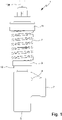
- Figures 1 to 4 show a proposed valve assembly 1 according to a first embodiment.
- the valve arrangement 1 is shown in a schematic side view and in 2 in a view rotated by 90°.
- 3 shows a schematic section of the valve assembly 1.
- the valve assembly 1 is shown in the closed position. 4 shows a cut corresponding to 3 with the valve assembly 1 in the open position.
- the valve arrangement 1 preferably has an inlet 2 and an outlet 3 .
- the inlet 2 and/or the outlet 3 are designed in particular as connections to the hoses or lines are connectable.
- the inlet 2 and/or outlet 3 preferably have appropriate connection devices, such as threads, quick-release couplings or the like.
- the valve arrangement 1 according to the first embodiment particularly preferably has exactly two connections, formed by the inlet 2 and the outlet 3 .
- the inlet 2 and the outlet 3 are preferably arranged or formed on a (common) main body or housing 4 of the valve arrangement 1 .
- the inlet 2 and the outlet 3 are preferably fluidly connected or can be connected, in particular via an inlet line 2A and/or an outlet line 3A.
- the inlet line 2A is preferably arranged or formed behind or downstream of the inlet 2 and/or in front of or upstream of the outlet 3 or the outlet line 3A.
- the outlet line 3A is preferably arranged or formed before or upstream of the outlet 3 and/or behind or downstream of the inlet 2 or the inlet line 2A.
- downstream and upstream refer here and in the following to the usual direction of flow of liquid, in particular water, during operation of the valve arrangement 1 (when it is open), in which the liquid flows through the valve arrangement 1 from the inlet 2 to the outlet 3 flows through.
- the inlet duct 2A and/or the outlet duct 3A are formed in the main body 4, respectively.
- the inlet 2 and the outlet 3 or their opening directions or the inlet line 2A and the outlet line 3A are preferably arranged transversely, in particular perpendicularly, to one another.
- other solutions are also possible here.
- a valve seat 5 is preferably arranged or formed between the inlet 2 and the outlet 3, in particular the inlet line 2A and the outlet line 3A.
- the valve seat 5 can be formed directly in or by the main body or the housing 4 and/or the inlet line 2A or the outlet line 3A, or, as in FIG 3 and 4 represented by an insert 5A.
- the insert 5A is preferably arranged or fixed in the inlet line 2A and/or outlet line 3A in a sealing or form-fitting manner.
- the insert 5A is fixed by means of a counterpart, in particular the counterpart being screwed into a screw channel of the drain line 3A.
- other solutions are also possible here.
- the valve arrangement 1 preferably has a valve element 6 which, in the closed position, such as in particular in 3 shown, sealingly against the valve seat 5 rests.
- the contact surface is preferably ring-shaped.
- the "closed position" of the valve arrangement 1 is preferably to be understood as meaning the position in which the valve element 6 rests against the valve seat 5 in a sealing manner.
- the fluid connection between inlet 2 and outlet 3, in particular inlet line 2A and outlet line 3A, is interrupted or closed or blocked, in particular by the sealing contact of valve element 6 on valve seat 5.
- the valve element 6 is preferably movably mounted or can be lifted off the valve seat 5, so that a fluid connection between the inlet 2 and the outlet 3, in particular the inlet line 2A and the outlet line 3A, is opened, released or established.
- the position in which the valve element 6 is (completely) lifted or moved away from the valve seat 5 is referred to below as the “open position” of the valve arrangement 1 . This is in 4 shown, which will be discussed in more detail later.
- valve element 6 is elongate or cylindrical or designed as a piston.
- other solutions are also possible here.
- the valve element 6 is preferably guided in the main body or housing 4 in a sealing manner.
- the valve arrangement 1 preferably has a clamping element or a spring 7 .
- the valve arrangement 1 or the valve element 6 is (pre)tensioned, preferably in the closed position or against the valve seat 5.
- the spring 7 is preferably a coil spring or a spring in which a spring wire 7A is wound in a helical form and/or helically.
- the spring 7 is a (helical) compression spring or coiled torsion spring. Under the action of an external load, in particular in the direction of the (screw) axis A of the spring 7 or compression of the spring 7, the spring wire 7A is preferably subject to torsion and an opposing force acts.
- the winding pitch of the spring 7 is preferably constant.
- the number of turns of the spring 7 is preferably greater than 4 or 5, and/or less than 16, in particular less than 12 or 10.
- the length of the spring 7 is preferably more than 4 cm, in particular more than 6 cm, and/or less than 10 cm, in particular less than 8 cm.
- the spring 7 is preferably spiral-shaped and/or has a preferably at least essentially cylindrical outer shape. However, slightly conical springs or the like are also conceivable.
- the spring 7 is preferably wound from a wire, in particular the spring wire 7A, which has an oval or rectangular cross-section or whose cross-section is non-circular, as in particular in the section according to FIG 3 and 4 shown.
- the cross section here means in particular the section perpendicular to the (longitudinal) axis of the wire, in particular the spring wire 7A, or a section along the (longitudinal) axis A or axis of symmetry or cylinder axis of the spring 7.
- the wire, in particular the spring wire 7A is preferably a square wire or profile wire, but not a round wire.
- the spring 7 particularly preferably has a rectangular wire cross section or the wire, in particular the spring wire 7A, is rectangular.
- a (helical or compression) spring with an oval or rectangular wire cross-section, i.e. with a non-circular or round wire cross-section, is also referred to as a stamp spring, tool spring or system spring.
- the spring 7 is preferably a stamp spring, tool spring or system spring.
- the spring 7 is preferably arranged on the valve arrangement 1 in such a way that its (longitudinal or spring) axis A corresponds to the opening or closing direction of the valve arrangement 1 or the valve element 6, and/or that a prestressing force of the spring 7 in Closing direction or on the valve element 6 acts.
- axial and radial preferably refer to the axis A or the axis A defined by the opening and closing direction of the valve arrangement 1.
- the axis A of the spring 7 or the closing direction of the valve element 6 corresponds to the direction of flow in the discharge line 3A (when the valve arrangement 1 is open).
- other solutions are also possible here.
- the spring 7 is preferably prestressed or mounted with a prestress.
- the valve arrangement 1 preferably has a first bearing element 8 on the side of the spring 7 facing away from the housing 4 or valve element 6 and/or a second bearing element 9 on the side of the spring 7 facing the housing 4 or valve element 6 .
- the spring 7 is preferably mounted or pretensioned between the bearing elements 8, 9, in particular compressed.
- the bearing elements 8, 9 are preferably plate-shaped or disk-shaped, in particular annular disk-shaped. In particular, the bearing elements 8, 9 form pressure plates or pressure washers.
- the prestressing or prestressing force of the spring 7 or the compression of the spring 7 and/or the distance between the bearing elements 8, 9 can preferably be set or adjusted, in particular by means of an adjustment device 10 of the valve arrangement 1.
- the adjustment device 10 preferably has a tensioning element 10A or is formed by such.
- the spring 7 and/or the bearing element 8 are/is tensioned against the tensioning element 10A.
- the setting device 10 is particularly preferably actuated by rotating the setting device 10, in particular the tensioning element 10A, in particular about an axis of symmetry of the setting device 10 or the tensioning element 10A and/or about the axis A of the spring 7.
- the adjustment device 10 is formed by a nut as a tensioning element 10A and a corresponding threaded rod 10B or has this.
- the threaded rod 10B preferably runs along the (spring) axis A or extends into the spring 7.
- the bearing element 8 is preferably moved towards or away from the bearing element 9 - depending on the direction of rotation - and/or the distance between the bearing elements 8, 9 and/or the compression or preload of the spring 7 is reduced or increased. elevated.
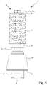
- an (internal) thread could also be formed directly on the bearing element 8, so that the bearing element 8 forms the tensioning element 10A. It is also possible that a screw is used as the clamping element 10A. The spring 7 and/or the bearing element 8 are/is then preferably tensioned against the screw head. Such a solution is exemplary for the second embodiment in Figures 5 to 7 shown.
- the valve arrangement 1 can optionally have a cover 11 in order to cover (partially or completely) the adjustment device 10, the tensioning element 10A and/or the bearing element 8 .
- the cover 11 preferably does not extend over the entire length of the spring 7 or preferably does not cover the spring 7 or only partially, in particular only one or two turns.
- the cover 11 can also be omitted entirely, as exemplified for the second embodiment in FIG Figures 5 to 7 shown.
- the spring 7 is particularly preferably arranged outside of the housing 4 and/or arranged at least substantially free of a housing and/or exposed or open to the environment or freely accessible from the outside.
- the valve arrangement 1 preferably has an intermediate element 12 .
- the intermediate element 12 is preferably arranged or mounted between the spring 7 or the bearing element 9 and the valve element 6 .
- the intermediate element 12 preferably extends radially or transversely, in particular perpendicularly, to the axis A.
- the intermediate element 12 is preferably mounted or arranged in a recess 4A or a gap, in particular of the main body or housing 4 .
- the recess 4A is in particular in 2 shown.
- the section of the recess 4A covered by the bearing element 9 is in 2 shown dashed.
- the intermediate element 12 is preferably secured or blocked against a rotary movement about the axis A, in particular in the recess 4A and/or in a form-fitting manner, and/or is mounted non-rotatably with respect to a rotation about the axis A.
- the intermediate element 12 is preferably mounted so that it can move axially.
- the recess 4A preferably extends in the axial direction, so that the intermediate element 12 can move in the recess 4A when opening or lifting the valve element 6 in the opening direction and when closing or lowering the valve element 6 in the closing direction, as in particular in 2 shown.
- the spring 7 preferably exerts a force, in particular a prestressing force, on the intermediate element 12, in particular via the bearing element 9.
- a force in particular a prestressing force
- the intermediate element 12 is preferably in direct contact with the valve element 6 , in particular axially, and/or is designed to transmit the prestressing force of the spring 7 to the valve element 6 .
- the valve element 6 is particularly preferably in contact with a central region of the intermediate element 6 or the intermediate element 12 is designed to center or deflect the prestressing force of the spring 7 onto the valve element 6 .
- the spring 7 or its prestressing force preferably acts axially on the intermediate element 12 and/or on an outer area or edge area or the outer ends of the intermediate element 12.
- the prestressing force of the spring 7 is preferably deflected via the intermediate element 12 or runs through the intermediate element 12 in the radial direction from the edge area or the outer ends of the intermediate element 12 into a central area or towards the axis A.
- the central area preferably acts in the axial direction on the valve element 6 or directs the force axially onto the valve element 6.
- the intermediate element 12 preferably forms an anti-twist device for the valve element 6.
- the valve arrangement 1 or the intermediate element 12 is preferably designed in such a way that when the spring 7 or its prestressing force is set or adjusted, or when the setting device 10 or the tensioning element 10A is actuated, in particular rotated, only forces in the axial direction or The closing direction can be transferred or can be transferred to the valve element 6 . Preferably, no torsional and/or shearing forces act on the valve element 6.
- the adjustment device 10 when the adjustment device 10 is actuated, torsional forces can occur which cause the first bearing element 8, the spring 7 and/or the second bearing element 9 to rotate about the adjustment axis, ie in particular the axis A.
- the intermediate element 12 is secured or blocked against such a rotary movement, in particular due to the bearing in the recess 4A. Accordingly, the rotational movement or torsional force is not transmitted to the valve element 6 .
- the intermediate element 12 is designed to absorb or dissipate the rotational movement or torsional forces, or to shield the valve element 6 from them.
- the intermediate element 12 is preferably designed as a feather key.
- the intermediate element 12 can also be a cotter pin, pin, bar or the like. It is also not necessary for the intermediate element 12 to be of elongate or pin-like design.
- the intermediate element 12 could also be anti-rotation (positive) be a secured cylinder piece or the like, for example a cylinder piece with at least one radially extending projection which positively engages in a corresponding recess.
- the valve arrangement 1 preferably weighs less than 1.5 kg, in particular less than 1 kg, and/or more than 0.3 kg or 0.4 kg, particularly preferably about 0.6 kg.
- valve arrangement 1 can preferably be connected to a system, plant or device (not shown), in particular with its inlet 2.
- valve 3 shows the valve arrangement 1 in the closed position, in which the valve element 6 is tensioned against the valve seat 5 or rests sealingly, in particular due to the spring 7 or its pretensioning force, which is particularly preferably deflected or centered on the valve element 6 by means of the intermediate element 12.
- a fluid connection between the inlet 2 and the outlet 3 is blocked or interrupted.
- a liquid preferably water, is present at the inlet 2 or in the inlet line 2A at a pressure which preferably corresponds to the pressure prevailing in the system or plant or device to which the Valve assembly 1 is connected by means of the inlet 2.
- the valve arrangement 1 preferably has an actuating means 13 in order to actuate or open the valve arrangement 1, in particular as a function of the fluid pressure, or to establish a fluid connection between the inlet 2 and the outlet 3.
- valve arrangement 1 or the actuating means 13 has an actuating space 14 which is preferably arranged or formed in the main body or housing 4 and/or downstream of the inlet 2 and/or upstream of the valve seat 5 .
- the valve assembly 1 is preferably for this purpose designed so that in the connected state a liquid with its liquid pressure is present or can be present on the actuating means 13 or in the actuating space 14 .
- the liquid pressure preferably acts with a force on the valve element 6 in the axial direction or in the opening direction or opposite to the prestressing force or closing direction, or the valve arrangement 1 is designed for this purpose.
- the actuating means 13 or the valve element 6 has an actuating section 15 for this purpose, in particular a step or an (annular) surface extending in the radial direction.
- other solutions are also possible here, in particular as will be explained later for the other embodiments.
- the valve arrangement 1 is preferably set or adjusted, in particular by means of the setting device 10, so that it remains in the closed position at (normal) operating pressure.
- the prestressing force of the spring 7, which acts on the valve element 6 in the closing direction is greater than the compressive force of the liquid, which acts on the valve element 6 or its actuating section 15 in the opening direction. The resulting force therefore acts in the closing direction.
- Operating pressure is preferably to be understood as meaning the (liquid) pressure at which the system or plant or device to which the valve arrangement 1 or its inlet 2 is connected is or can be operated, and /or the (liquid) pressure for which the system, plant or device is designed.
- the operating pressure is therefore preferably the normally prevailing pressure of the system or the plant or device (in operation).
- “operating pressure” is preferably not to be understood as meaning a specific pressure, but rather a pressure range, for example 50 to 200 bar or 50 to 500 bar.
- the direction of the resulting force preferably changes and then acts in the opening direction.
- the pressure required for this is also referred to as the response pressure.
- the response pressure is preferably above the operating pressure (range) or the maximum pressure for which the system or the plant or device to the / the the valve arrangement 1 or whose inlet 2 is connected is designed. However, the response pressure is preferably below a maximum permissible excess pressure of the system or the plant or device.
- the response pressure is preferably at most 5%, 10% or 15% above the maximum permissible operating pressure.
- valve element 6 When the response pressure is reached or exceeded, the valve element 6 is preferably lifted off the valve seat 5 or moved in the opening direction, in particular against the biasing force of the spring 7 . This preferably leads to an axial movement of the intermediate element 12 and/or bearing element 9 in the opening direction or to a (further) compression of the spring 7.
- the stroke of the valve element 6 or how far the valve element 6 is lifted from the valve seat 5 preferably depends on the liquid pressure.
- the stroke increases (continuously) with increasing pressure until a maximum stroke is reached.
- the pressure required for the maximum stroke is also referred to as the opening pressure.
- the valve arrangement 1 is preferably fully open. This is an example in 4 shown.
- the relationship between pressure and stroke is preferably at least essentially linear.
- the opening pressure is preferably below the maximum permissible excess pressure of the system or the plant or device.
- the opening pressure is preferably at most 5%, 10% or 15% above the response pressure. It is also possible for the valve element 6 to open directly with full lift when the response pressure is reached, ie the opening pressure corresponds at least essentially to the response pressure.
- liquid can flow from the inlet 2 to the outlet 3.
- the volume flow or the flow rate or flow rate from the inlet 2 to the outlet 3 preferably depends on the stroke of the valve element 6, the volume flow being greater the more the valve element 6 is lifted.
- the valve arrangement 1 or the discharge line 3A preferably has a nozzle or cross-sectional constriction 16 behind or downstream of the valve seat 5 .
- the cross-sectional constriction 16 can be formed directly in the main body or housing 4 or the discharge line 3A, or by an insert in the discharge line 3A, preferably by the same insert 5A that also forms the valve seat 5.
- a cross-sectional constriction 16 is preferably to be understood here as meaning that the effective or hydraulic cross-section through which liquid can flow is smaller in the region of the cross-sectional constriction 16 than at the valve seat 5.
- the valve seat 5 preferably delimits an opening through which the liquid can flow when the valve element is lifted 6 can flow to the outlet 3, the opening cross section preferably being larger than the cross section of the cross-sectional constriction 16 arranged downstream.
- the hydraulic diameter of the valve seat opening is preferably greater than the hydraulic diameter of the cross-sectional constriction 16.
- the opening cross-section of the opening delimited by the valve seat 5 and the cross-section of the cross-sectional constriction 16 are preferably circular, the diameter of the cross-sectional constriction 16 being smaller.
- other solutions are also possible here, as will be explained later with reference to the further embodiments.
- a pressure increase or an additional pressure or a back pressure is preferably generated by the cross-sectional constriction 16 upstream of the cross-sectional constriction, in particular in comparison to a valve arrangement without a cross-sectional constriction 16.
- the stroke of the valve element 6 is preferably supported or facilitated by the narrowing of the cross section 16 or the associated dynamic pressure.
- an (additional) compressive force preferably acts on the valve element 6 in the opening direction and/or on the (axial) end face 6A of the valve element 6, in particular at least essentially over the entire surface.
- the cross-sectional constriction 16 preferably achieves a greater stroke of the valve element 6 or faster or wider opening of the valve arrangement 1, in particular in comparison to a valve arrangement without a cross-sectional constriction 16.
- the cross-sectional constriction 16 preferably forms a dynamic opening aid.
- the pressure preferably drops (again).
- the valve assembly 1 preferably closes (again) when the force acting on the valve element 6 corresponds to the biasing force of the spring 7 and/or the liquid pressure in the plant or device or the system or at the inlet 2 of the valve assembly 1 is below a certain pressure , the so-called closing pressure, falls.
- the closing pressure is particularly preferably below the response pressure, in particular by more than 2%, 5%, 10% or 15%.
- the closing pressure can be above or below the maximum permissible operating pressure.
- the closing pressure is preferably above the maximum permissible operating pressure.
- a closing pressure that is lower than the response pressure is preferably achieved by the cross-sectional constriction 16 .
- the cross-sectional constriction 16 causes additional pressure on the valve element 6. If the liquid pressure in the plant or device or the system or at the inlet 2 has (again) reached the response pressure, the valve element 6 preferably does not act only the response pressure force, but also the pressure force caused by the cross-sectional constriction 16 . In particular, the total compressive force is even greater than the prestressing force, so that the valve arrangement 1 remains open. Only when the closing pressure has been reached or fallen below has the compressive force on the valve element 6 preferably decreased to such an extent that the closed position is assumed (again).
- the prestressing force of the spring 7 must preferably be overcome.
- the response pressure can preferably be set or adjusted via the setting device 10 .
- the response pressure is a property of the valve arrangement 1, namely the pressure required for opening.
- the opening pressure and/or closing pressure are preferably dependent on the response pressure and are determined in particular by the design or geometry of the valve arrangement 1, for example the diameter of the cross-sectional constriction 16.
- the valve arrangement 1 is preferably designed for a liquid pressure or operating pressure of at least 50 bar, in particular 100 bar or 200 bar and/or at most 300 bar, 500 bar or 700 bar.
- the adjustable response pressure is preferably at least 10, 20 or 50 bar, in particular 100 bar or 200 bar and/or at most 300 bar, 500 bar or 700 bar.
- the valve arrangement 1 according to the first embodiment is preferably a safety valve arrangement.
- a fluid connection is to be blocked or released under pressure control.
- FIG. 5 to 7 a second embodiment of the proposed valve assembly 1 is shown, which can be used in particular as a safety valve assembly.
- FIG. 5 shows figure 5 the valve assembly 1 according to the second embodiment in a schematic side view and Figures 6 and 7 each in a schematic section in the closed position or open position.
- the second embodiment differs from the first embodiment in particular in the design or arrangement of the inlet 2, outlet 3, main body or housing 4, valve seat 5 and/or valve element 6.
- the same explanations and explanations regarding the spring 7 preferably apply.
- the clamping element 10A of the adjustment device 10 is preferably designed as a screw.
- other solutions are also possible here, in particular as described for the first embodiment.
- valve element 6 is preferably designed as a valve ball.
- the valve arrangement 1 preferably has a piston rod 17 between the intermediate element 12 and the valve element 6, which is in particular designed as a valve ball.
- the prestressing force exerted by the spring 7 can be transmitted from the intermediate element 12 via the piston rod 17 to the valve element 6, which is designed in particular as a valve ball.
- the valve element 6 embodied in particular as a valve ball can be tensioned or tensioned by the piston rod 17 against the valve seat 5 .
- valve element 6 could itself be piston-shaped and/or abut directly against the intermediate element 12, as in the first embodiment, and/or the piston rod 17 could be formed integrally with the valve element 6, e.g. B. have a hemispherical, axial end.
- the main body or the housing 4 is preferably at least essentially cylindrical.
- the opening direction of the inlet 2 or the inlet line 2A preferably runs in the axial direction.
- the actuating means 13 is preferably formed by the surface of the valve element 6 facing the inlet 2 and/or the actuating space 14 directly in front of the valve element 6 .
- the valve arrangement 1 preferably opens or the valve element 6 is lifted, in particular together with the piston rod 17, when the compressive force on the actuating means 13 or on the surface of the valve element 6 facing the inlet 2 reaches or exceeds the prestressing force exerted on the valve element 6 by the spring 7 . This takes place in particular at the (set) response pressure, as described for the first embodiment.
- the valve arrangement 1 in particular the main body or the housing 4 , preferably has one or more transverse channels 18 downstream of the valve seat 5 .
- the transverse channels 18 preferably run radially or transversely, in particular orthogonally, to the axis A or the inlet line 2A or the opening/closing direction of the valve element 6.
- transverse channels 18 distributed over the circumference of the valve arrangement 1 or the main body or housing 4 are provided, for example 2, 4, 6 or 8 transverse channels 18.
- the transverse channels 18 preferably open out on the outside of the main body or housing 4 or into the environment.
- the transverse channels 18 can (together) form the outlet 3 .
- the valve arrangement 1 preferably has a deflection part 19 .
- the deflection part 19 is conical or truncated or has the shape of the lateral surface of a truncated cone.
- the deflection part 19 preferably surrounds or encloses the main body or the housing 4 (radially), at least partially, in particular in the region of the transverse channels 18.
- the axis of symmetry of the deflection part 19 preferably corresponds to the axis A.
- the opening diameter of the deflection part 19 increases in the direction of the Inlet 2 or in the closing direction of the valve element 6 to.
- the deflection part 19 is preferably fastened to the housing 4 .
- Liquid escaping from the transverse channels 18 can be deflected or deflected via the deflection part 19 .
- (Radially) escaping liquid can preferably be deflected in another direction, in particular in the axial direction, in particular by the conical shape, preferably by the liquid bouncing off the deflection part 19 or its inner wall.
- the deflection part 19 is preferably open at its axial, widened end, so that the liquid can escape there into the environment.
- the outlet 3 is formed in this way.
- the drain 3 preferably has an annular opening and/or surrounds the main body or housing 4 and/or is bounded (radially) by the main body or housing 4 and the deflector part 19 .
- the direction of flow of liquid exiting the outlet 3 is preferably opposite to the direction of flow of liquid entering through the inlet 2 .
- liquid is preferably not drained off via a line or hose, or the outlet 3 has no connection for a line or hose.
- the liquid is preferably discharged or drained directly into the environment, in particular via the transverse channels 18 and/or the deflection part 19. This can preferably ensure that if the valve arrangement 1 is opened, liquid is drained and the liquid pressure is reduced accordingly, in particular since no hose or the like can be used for draining, which in turn could be blocked.
- the cross-sectional constriction 16 is preferably formed by the transverse channels 18 . In this way, corresponding effects and advantages as described for the first embodiment can be achieved.
- the cross-sectional constriction 16 is preferably to be understood as the sum of the cross-sections of the individual transverse channels 18 , in particular the hydraulic cross-section of the transverse channels 18 or the (total) flow cross-section of a liquid flowing through the transverse channels 18 .
- the (hydraulic) cross section of the opening of the valve seat 5 is larger than the (hydraulic) cross section of the transverse channels 18 or the sum of all individual cross sections of the transverse channels 18.
- the hydraulic diameter of the valve seat opening is larger than the hydraulic diameter of the through the Cross channels 18 is formed.
- the liquid when it flows through the opened valve seat 5 and then through the transverse channels 18, in particular to a dynamic pressure upstream of the transverse channels 18, preferably due to the (hydraulic) narrowing of the cross section 16 formed by the transverse channels 18.
- This preferably leads to the same or corresponding effects and advantages as described for the first embodiment, in particular faster opening and/or larger stroke and/or closing pressure lying below the response pressure.
- a third embodiment of the proposed valve arrangement 1 is shown, which can be used in particular as a safety valve arrangement.
- the valve assembly 1 according to the third embodiment in a schematic side view and Figures 9 and 10 each in a schematic section in the closed position or open position.
- the valve arrangement 1 according to the third embodiment is preferably designed similarly to the valve arrangement 1 according to the second embodiment, in particular with transverse channels 18 and an optional deflection part 19.
- the valve arrangement 1 according to the third embodiment differs from the valve arrangement 1 according to the second embodiment essentially by the formation of the valve element 6.
- valve element 6 is sleeve-shaped or at least essentially hollow-cylindrical and/or surrounds or encloses the in particular at least essentially cylindrical main body or housing 4.
- the axis of symmetry of the valve element 6 preferably corresponds to the axis A and/or the main body or housing 4 and the valve element 6 are preferably arranged concentrically to one another.
- the valve seat 5 is preferably formed at or (immediately) downstream of the openings of the transverse channels 18, which is particularly preferably annular and/or closed in the closed position by the particularly sleeve-shaped valve element 6.
- valve seat 5 is preferably formed by a sealing ring or the like, which (radially) surrounds or encloses the main body or the housing 4 .
- a sealing ring or the like which (radially) surrounds or encloses the main body or the housing 4 .
- valve element 6 When the response pressure is reached or exceeded, the valve element 6 can be moved or lifted off the valve seat 5, preferably against the biasing force of the spring 7.
- the valve element 6 has an (annular) actuating surface for this purpose and/or an (annular) actuating space 14 is formed between the outlet openings of the transverse channels 18 and the valve seat 5 .
- an annular gap is preferably released through which the liquid can be discharged into the environment, in particular via the deflection part 19.
- the annular gap on the valve seat 5 can form the cross-sectional constriction 16 .
- the (hydraulic) cross section or hydraulic diameter of the gap (immediately) downstream of the valve seat 5 is smaller than the (hydraulic) cross section or hydraulic diameter of the (sum of) transverse channels 18 upstream of the valve seat 5.
- the deflection part 19 is preferably arranged or attached to the valve element 6 .
- the deflection part 19 can be moved together with the valve element 6 .
- valve arrangement 1 preferably has no intermediate element 12 .
- valve arrangement 1 preferably also has an anti-rotation device (not shown), which in particular allows an axial movement of the valve element 6 but prevents or blocks a rotary movement about the axis A.
- the valve element 6 can have projections pointing radially inwards, which are guided axially in corresponding grooves of the main body or housing 4, or vice versa.
- an anti-twist device is also conceivable in the other embodiments.
- valve arrangement 1 according to the third embodiment can also have an intermediate element 12 as described and illustrated for the other embodiments.
- a fourth embodiment of the proposed valve arrangement 1 is shown, which can be used in particular as a circulation valve arrangement.
- the valve assembly 1 according to the fourth embodiment in a schematic side view and 12 and 13 each in a schematic section in the closed position or open position.
- biasing force of spring 7 also acts in the fourth embodiment in the same direction as in the previous embodiments, i.e. in particular axially in the direction of intermediate element 12 or valve seat 5 or valve element 6 or main body/housing 4.
- Spring 7 is preferred a compression spring.
- the spring 7 according to the fourth embodiment in particular as in the other embodiments, is provided on its side facing away from the main body/housing 4 or valve seat 5 or valve element 6 or intermediate element 12 or the side on which the adjustment device 10 is provided is mounted immovably during operation or movably only for adjusting the prestressing force of the spring 7 and otherwise fixed axially.
- the side of the spring 7 that faces the main body/housing 4 or valve seat 5 or valve element 6 or intermediate element 12 or the side that faces away from the adjusting device 10 is movably mounted, in particular so that the spring 7 can be released when the Valve element 6 is compressed by the valve seat 5, or in such a way (directly) coupled to the valve element 6 that an axial movement or lifting of the valve element 6 leads to a corresponding axial movement of the end of the spring 7 on this side.
- the spring used in particular also a compression spring, acts in exactly the opposite direction and pulls the valve element against the valve seat.
- the side of the spring facing the main body or housing or valve seat is fixedly mounted. Accordingly, the side facing away, in particular the side with the adjustment device, is also movably mounted during operation, in particular so that lifting the valve element from the valve seat leads to an axial movement of this end, in particular together with the adjustment device, or to a compression of the spring.
- this design means that the valve element or a piston rod formed by it must extend through the entire spring in the prior art so that the spring can exert a corresponding prestressing force on the valve element.
- valve element 6 is preferably designed as a piston or has a piston, in particular as in the first embodiment.
- other solutions are also possible here, for example with a valve ball as in the second embodiment.
- the valve element 6 preferably only extends as far as the intermediate element 12.
- the valve arrangement 1 or the valve element 6 does not have a piston rod which—at least partially—extends through the spring 7, as is customary in the prior art.
- the valve arrangement 1 according to the fourth embodiment preferably has an outlet 20 which is different from the inlet 2 and the outlet 3.
- the inlet 2, the outlet 3 and/or the outlet 20 are preferably designed as connections to which hoses or lines can be connected.
- the inlet 2, outlet 3 and/or outlet 20 preferably have corresponding connection devices, such as threads, quick-release couplings or the like.
- the inlet 2 and outlet 20 or their openings or connections are preferably arranged opposite one another and/or a liquid can flow through the valve arrangement 1 at least essentially in a straight line from the inlet 2 to the outlet 20 .
- the outlet 3 or its opening or connection is preferably arranged transversely, in particular orthogonally, to the inlet 2 and/or outlet 20 .
- the inlet 2, outlet 3 and/or outlet 20 are preferably arranged transversely, in particular orthogonally, to the opening or closing direction of the valve element 6 and/or the axis A.
- the inlet direction or outlet direction, the discharge direction and the opening/closing direction or axis A are each transverse, in particular orthogonal, to one another.
- other arrangements are also possible here, in particular through a corresponding design of the main body or housing 4.
- a check valve 21 is preferably arranged between the inlet 2 and the outlet 20 .
- the valve arrangement 1 is preferably designed in such a way, or the response pressure is set in such a way that the check valve 21 is open during normal operation and the valve formed by the valve seat 5 and the valve element 6 is closed.
- This position is preferably the closed position of the valve arrangement 1.
- the terms "closed position” and “open position” therefore preferably refer to the valve seat 5 or the valve element 6, in particular as in the other embodiments.
- the valve arrangement 1 can be in the closed/open position when the check valve 21 is open/closed.
- Normal operation is preferably to be understood as an operation of the valve arrangement 1 or the plant, the system or the device to which the valve arrangement 1 is connected, during which a liquid is discharged downstream of the outlet 20 . This will be discussed in more detail later with reference to 14 received, which shows an example of the use of the proposed valve assembly 1 in a high-pressure cleaning device. "Normal operation” is also referred to as "conveying operation”.
- the inlet 2 and the outlet 20 are preferably fluidically connected and/or the inlet 2 and the outlet 3 are fluidically separated.
- the outlet 3 and the outlet 20 are preferably not fluidically connectable or are (permanently) sealed from one another, in particular both in the closed position and in the open position of the valve arrangement 1.
- a control channel 22 is preferably provided downstream of the check valve 21 or between the check valve 21 and the outlet 20 , which fluidically connects the outlet 20 to the actuation chamber 14 .
- the actuating space 14 is preferably arranged or formed annularly and/or concentrically to the axis A.
- the valve arrangement 1 preferably has a piston 23 .
- the piston 23 preferably delimits the actuation space 14 axially and/or is arranged symmetrically to the axis A or the opening or closing direction of the valve element 6 .
- the axis of symmetry of the piston 23 corresponds to the axis A.
- the piston 23 is preferably arranged between the actuation chamber 14 and the valve element 6 and/or lies upstream of the valve seat 5 or on the inlet side on the valve element 6 and/or is connected to it.
- the biasing force of the spring 7 acts, in particular via the valve element 6, on the piston 23 or tensions it against the main body or the housing 4, as shown in FIG 12 shown.
- the piston 23 preferably has a step or the like, so that the actuation space 14 is formed between the main body/housing 4 and the step of the piston 23 .
- the piston 23 is preferably arranged transversely, in particular orthogonally, to the inlet direction or inlet line 2A.
- the piston 23 preferably protrudes through the inlet line 2A or liquid can flow around it in the inlet line 2A.
- the piston 23 can have a reduced diameter in the area of the inlet line 2A.
- the actuating means 13 preferably has the actuating space 14 and/or the piston 23 or is formed by them.
- the valve arrangement 1 is preferably designed to separate the fluidic connection between the inlet 2 and the outlet 20 and/or to establish a fluidic connection between the inlet 2 and the outlet 3 when the fluid pressure on the outlet side or at the outlet 20 and/or in the actuation chamber 14 exceeds the response pressure reached or exceeded.
- a pressure increase or pressure peak or a pressure pulse occurs on the outlet side. This preferably causes the check valve 21 to be closed or the fluid connection between the inlet 2 and the outlet 20 to be blocked.
- the piston 23 is preferably designed to lift the valve element 6 off the valve seat 5 when the response pressure is reached or exceeded.
- the increase in pressure or pressure peak or the pressure pulse at outlet 20 preferably causes an increase in pressure in actuation chamber 14 or on piston 23, in particular via control channel 22 is moved or pressed, so that the valve element 6 resting on or attached to the piston 23 is lifted off the valve seat 5 .
- the open position is in 13 shown.
- the check valve 21 is preferably closed and the valve element 6 is lifted off the valve seat 5 so that a fluid connection between the inlet 2 and the outlet 20 is interrupted and a fluid connection between the inlet 2 and the outlet 3 is established.
- valve arrangement 1 in the case of the valve arrangement 1 according to the fourth embodiment, a narrowing of the cross section 16 behind the valve seat 5, as in the other embodiments, can be provided and advantageous.
- the response pressure is preferably set or adjustable in such a way that it lies between the normal operating pressure and the increased pressure when the liquid outlet downstream of the outlet 20 is interrupted.
- the response pressure is preferably between 510 bar and 650 bar.
- the valve assembly 1 is in normal operation or when liquid can escape downstream of the outlet 20 in the closed position - in particular with open check valve 21 - and / or idle operation or when a Escape of liquid downstream of the outlet 20 is blocked in the open position - in particular with the check valve 21 closed.
- a proposed high-pressure cleaning device 100 is shown in a block diagram-like view, which preferably has at least one proposed valve arrangement 1 .
- the high-pressure cleaning device 100 preferably has two proposed valve arrangements 1, namely a first valve arrangement 1, which is designed as a circulation valve arrangement 1A, and a second valve arrangement 1, which is designed as a safety valve arrangement 1B.
- FIG. 14 shows the high-pressure cleaning device 100 in conveying operation, in which a liquid, in particular water, preferably as a jet S, is discharged from the high-pressure cleaning device 100.
- the high-pressure cleaning device 100 preferably has a pump 110, in particular a high-pressure pump.
- the pump 110 is preferably connected to the circulating valve arrangement 1A, in particular its inlet 2, via a supply line 120.
- the high-pressure cleaning device 100 preferably has a valve pistol 130 which is connected in particular via a connecting line 140 to the circulating valve arrangement 1A, in particular to its outlet 20 .
- a return line 150 of the high-pressure cleaning device 100 is preferably connected to the circulation valve arrangement 1A, in particular its outlet 3.
- the high-pressure cleaning device 100 is preferably connected or connectable (not shown) upstream of the pump 110 to a liquid reservoir, a water line, a water distribution system or the like. It is also possible for the high-pressure cleaning device 100 to have a liquid reservoir, a liquid container or the like.
- the pump 110 is switched on and the valve pistol 130 is actuated or opened.
- a liquid in particular water, in particular from a reservoir or the like
- the valve gun preferably through supply line 120, circulation valve arrangement 1A and/or connecting line 140.
- Inlet 2 and outlet 20 of circulation valve arrangement 1A are preferably fluidic with one another connected, in particular the check valve 21 is open.
- the liquid is preferably delivered as a jet S via the valve pistol 130, in particular under high pressure.
- High pressure is preferably understood to mean a pressure of at least 50 bar or 100 bar.
- a jet S can preferably be emitted by means of the high-pressure cleaning device 100 under a pressure of up to 500 bar or 700 bar or more.
- the operating pressure or working pressure of the high-pressure cleaning device 100 is at least 50 bar or 100 bar, in particular at least 300 bar, and/or at most 700 bar, in particular at most 500 bar.
- the volume flow of the liquid through the valve arrangement 1 is preferably more than 10 l/min, in particular more than 25 l/min, and/or less than 100 l/min, in particular less than 75 l/min.
- the safety valve arrangement 1B is preferably connected downstream of the pump 110 or upstream of the circulating valve arrangement 1A or between the pump 110 and the circulating valve arrangement 1A or to the supply line 120, in particular with its inlet 2. During delivery operation, the safety valve arrangement 1B is preferably in the closed position, in the inlet 2 and outlet 3 are fluidically separated.
- the pretensioning forces of the respective springs 7 of the valve assemblies 1 are preferably set in such a way that during delivery operation or in the operating pressure (range) then prevailing, the valve assemblies 1 are in their closed position or the respective valve elements 6 are tensioned against the respective valve seats 5. If the valve gun 130 is closed - while the pump 110 is running - and in particular the jet S is interrupted, this preferably leads to a pressure pulse in the connecting line 140 which exceeds the response pressure of the circulating valve arrangement 1A or corresponds to it, so that the circulating valve arrangement 1A assumes the open position, in which the inlet 2 and outlet 3 are fluidly connected.
- the check valve 21 is preferably closed, in particular by the pressure pulse, or the fluid connection between the inlet 2 and the outlet 20 is interrupted.
- the liquid is preferably directed to the return line 150 via the circulation valve assembly 1A.
- the liquid is preferably discharged via the return line 150 or fed back into the system upstream of the pump 110, for example fed back into the reservoir.
- Operation with the valve gun 130 closed is also referred to as idling operation.
- the liquid is pumped and/or circulated into the return line 150 via the pump 110 and the circulating valve arrangement 1A.
- the safety valve arrangement 1B is preferably in the closed position in (normal) idling operation.
- the response pressure of the safety valve arrangement 1B is set in such a way that it is above the operating pressure (range) in delivery operation and idle operation.
- valve pistol 130 If the valve pistol 130 is opened (again), this preferably leads to a drop in pressure in the connecting line 140 and/or at the outlet 20 or actuation chamber 14 of the circulating valve arrangement 1A.
- the drop in pressure preferably leads to a closing movement of the valve element 6 of the circulation valve arrangement 1A, in particular due to the prestressing force of the spring 7, so that the closed position is assumed (again).
- the closed position preferably leads to an increase in pressure in the supply line 120 or at the inlet 2 or the inlet line 2A of the circulation valve arrangement 1A, in particular due to the conveying of the liquid by means of the pump 110, so that the check valve 21 opens (again) and liquid (again) is conveyed to the outlet 20 so that it can be delivered to the valve gun 130.
- the high-pressure cleaning device 100 is then preferably (again) in delivery mode.
- the response pressure of the safety valve arrangement 1B is preferably set in such a way that the safety valve arrangement 1B remains in the closed position even if the pressure rises briefly, caused by the change between delivery operation and idling operation or vice versa.
- the response pressure is preferably above the pressures occurring during these changes.
- the safety valve arrangement 1B or its response pressure is preferably set in such a way that it only opens when the pressure is higher than the pressures that usually occur, for example 5% or 10% higher.
- liquid is preferably drained off or removed from the system or the high-pressure cleaning device 100 via the safety valve arrangement 1B, as explained above, so that the pressure can drop again or the overpressure can be relieved.
- the safety valve arrangement 1B preferably closes (again) when the closing pressure is reached, which is preferably below the response pressure.
- the safety valve arrangement 1B is preferably connected to the supply line 120 . In this way, it is ensured that the safety valve arrangement 1B can trigger or open both during delivery operation and during idling operation.
Abstract
Die Erfindung betrifft eine Ventilanordnung (1), insbesondere eine Sicherheitsventilanordnung (1B) oder eine Umlaufventilanordnung (1A), die gesteuert vom Flüssigkeitsdruck öffnet und schließt. Vorschlagsgemäß ist eine Druckfeder (7), die ein Ventilelement (6) gegen einen Ventilsitz (5) vorspannt, als Stempelfeder ausgebildet. Gemäß einem weiteren Aspekt kann die Ventilanordnung ein Zwischenelement (12) aufweisen, über das die Vorspannkraft der Feder (7) auf das Ventilelement (6) übertragbar ist, wobei das Zwischenelement (12) gegen ein Drehen um eine Längs- bzw. Schrauben-Achse der Feder (7) gesichert ist. Gemäß einem weiteren Aspekt ist stromab des Ventilsitzes (5) eine Querschnittsverengung (16) vorgesehen, um ein Abheben des Ventilelements (6) vom Ventilsitz (5) zu unterstützen.

Description
Die vorliegende Erfindung betrifft eine Ventilanordnung gemäß Oberbegriff des Anspruchs 1 sowie eine Hochdruckreinigungsvorrichtung.The present invention relates to a valve arrangement according to the preamble of
Insbesondere betrifft die vorliegende Erfindung Sicherheitsventilanordnungen und Umlaufventilanordnungen. Die erfindungsgemäße Ventilanordnung kann jedoch auch für andere Anwendungen eingesetzt werden und vorteilhaft sein.In particular, the present invention relates to safety valve assemblies and circulation valve assemblies. However, the valve arrangement according to the invention can also be used for other applications and can be advantageous.
Sicherheitsventile dienen dazu, ein hydraulisches System gegen einen ungewollten Überdruck zu schützen. Sie werden daher auch als Überdruckventile bzw. Druckbegrenzungsventile bezeichnet. Diese Begriffe sind im Folgenden daher vorzugsweise als synonym zu verstehen.Safety valves are used to protect a hydraulic system against unwanted overpressure. They are therefore also referred to as pressure relief valves or pressure relief valves. These terms are therefore preferably to be understood as synonymous below.
Sicherheitsventilanordnungen werden insbesondere bei Kolbenpumpen, wie einer Hochdruckreinigungsvorrichtung bzw. Wasserstrahlreinigungsvorrichtung, verwendet.Safety valve arrangements are used in particular in piston pumps, such as a high-pressure cleaning device or water jet cleaning device.
Das Öffnen und Schließen einer Sicherheitsventilanordnung ist vorzugsweise durch den herrschenden Flüssigkeits- bzw. Wasserdruck gesteuert bzw. geregelt.The opening and closing of a safety valve arrangement is preferably controlled or regulated by the prevailing liquid or water pressure.
Im Normalbetrieb, insbesondere also bei üblichem Betriebsdruck, ist die Sicherheitsventilanordnung vorzugsweise geschlossen. Sobald ein bestimmter, sogenannter Ansprechdruck erreicht bzw. überschritten wird, öffnet die Sicherheitsventilanordnung. Das Öffnen erfolgt also vorzugsweise, wenn ein kritischer Druck oberhalb des Betriebsdrucks erreicht bzw. überschritten ist, insbesondere bei einem ungewünschten bzw. unzulässigen Druckanstieg. Über die geöffnete Sicherheitsventilanordnung kann dann Fluid aus dem System abgeleitet bzw. umgeleitet werden, insbesondere also der Druck wieder gesenkt werden.In normal operation, ie in particular at normal operating pressure, the safety valve arrangement is preferably closed. As soon as a certain, so-called response pressure is reached or exceeded, the safety valve arrangement opens. The opening therefore preferably takes place when a critical pressure above the operating pressure is reached or exceeded, in particular in the event of an undesired or impermissible increase in pressure. Fluid can then be drained or diverted from the system via the opened safety valve arrangement, ie in particular the pressure can be lowered again.
Vorzugsweise schließt die Ventilanordnung (wieder), sobald der Druck unter einen bestimmten Wert gefallen ist, den sogenannten Schließdruck. Der Schließdruck entspricht dem Ansprechdruck oder liegt unterhalb des Ansprechdrucks.The valve arrangement preferably closes (again) as soon as the pressure has fallen below a certain value, the so-called closing pressure. The closing pressure corresponds to the response pressure or is below the response pressure.
Übliche, aus dem Stand der Technik bekannte Sicherheitsventilanordnungen umfassen eine Spiralfeder, die direkt auf einen Kolben drückt und diesen gegen einen Ventilsitz presst bzw. spannt. Die Sicherheitsventilanordnung öffnet, wenn der Fluiddruck auf den Kolben den durch die Feder ausgeübten Druck überschreitet bzw. überwindet. Die Feder ist mit einer Hülse eingehaust, wobei sich die Hülse drehen lässt, um die Vorspannkraft der Feder und somit den Ansprechdruck zu verstellen bzw. einzustellen. Alternativ, insbesondere bei sehr großen Hülsen, wird eine Einstellschraube verbaut. Die Hülse ist dann fest und die Feder wird über die Einstellschraube gespannt.Customary safety valve arrangements known from the prior art comprise a spiral spring which presses directly on a piston and presses or tensions it against a valve seat. The safety valve assembly opens when the fluid pressure on the piston exceeds or overcomes the pressure exerted by the spring. The spring is encased in a sleeve, which can be turned to adjust the preload force of the spring and thus the response pressure. Alternatively, especially with very large sleeves, an adjusting screw is installed. The sleeve is then tight and the spring is tensioned via the adjusting screw.
Die vorliegende Erfindung betrifft auch sogenannte Umlaufventile, die auch als Bypassventile oder Unloader-Ventile bezeichnet werden. Diese Begriffe sind im Folgenden daher vorzugsweise als synonym zu verstehen.The present invention also relates to so-called circulation valves, which are also referred to as bypass valves or unloader valves. These terms are therefore preferably to be understood as synonymous below.
Vorzugsweise sperrt und öffnet eine Umlaufventilanordnung ebenfalls in Abhängigkeit vom herrschenden Flüssigkeits- bzw. Wasserdruck, hat also vorzugsweise eine zumindest ähnliche Funktionsweise wie eine Sicherheitsventilanordnung und damit einhergehend vorzugsweise auch einen ähnlichen Aufbau.Preferably, a circulating valve arrangement also blocks and opens as a function of the prevailing liquid or water pressure, so it preferably has at least a similar function to a safety valve arrangement and, as a result, preferably also has a similar structure.
Vorzugsweise dient eine Umlaufventilanordnung als Druckminderer und/oder um eine Pumpe in einen Leerlauf zu schalten. Eine Umlaufventilanordnung dient vorzugsweise dazu, einen Druck herunterzuregeln und/oder einen Fluidstrom, insbesondere wenn er nicht benötigt wird, umzuleiten bzw. abzuleiten. Der Betrieb, bei dem eine solche Umleitung erfolgt, wird auch als Bypassbetrieb oder Leerlaufbetrieb bezeichnet. Eine Umlaufventilanordnung hat vorzugsweise mindestens zwei Funktionen, nämlich eine Pumpe in den Leerlauf zu schalten und den Druck herunterzuregeln bzw. zu mindern.A circulating valve arrangement preferably serves as a pressure reducer and/or to switch a pump to an idle state. A circulating valve arrangement preferably serves to regulate down a pressure and/or to divert or divert a fluid flow, in particular when it is not required. Operation in which such a diversion takes place is also referred to as bypass operation or idle operation. A spool valve assembly preferably has at least two functions, namely to idle a pump and to turn down or reduce the pressure.
Beispielsweise wird bei einer Hochdruckreinigungsvorrichtung eine Flüssigkeit, insbesondere Wasser, durch eine Pumpe unter Druck gesetzt und üblicherweise über eine angeschlossene Ventilpistole ausgegeben, insbesondere für Reinigungszwecke. Wird die Ventilpistole geschlossen, weil (temporär) keine weitere Abgabe von Flüssigkeit gewünscht ist, so müsste die Pumpe gegen die geschlossene Ventilpistole arbeiten. Um dies zu Verhindern, wird vorzugsweise eine Umlaufventilanordnung eingesetzt, die den Flüssigkeitsstrom umleitet, insbesondere zurück zur Pumpe, besonders bevorzugt so dass die Flüssigkeit in einem Kreislauf förderbar ist.For example, in a high-pressure cleaning device, a liquid, in particular water, is pressurized by a pump and usually dispensed via a connected valve pistol, in particular for cleaning purposes. If the valve gun is closed because (temporarily) no further delivery of liquid is desired, the pump would have to work against the closed valve gun. In order to prevent this, a circulating valve arrangement is preferably used, which diverts the flow of liquid, in particular back to the pump, particularly preferably so that the liquid can be conveyed in a circuit.
Eine aus dem Stand der Technik bekannte Umlaufventilanordnung ist beispielsweise in der
Bei Schließen der Ventilpistole, also Zusammenbrechen der Flüssigkeitsströmung, schließt das Rückschlagventil. Gleichzeitig entsteht stromab des Rückschlagventils ein Druckimpuls, der auf die Kolbenstange wirkt, so dass diese vom Ventilsitz abgehoben wird und sich die Bypassleitung öffnet. In diesem Bypassbetrieb bzw. Leerlaufbetrieb bleibt das Rückschlagventil geschlossen und das Bypassventil geöffnet und wird die Flüssigkeit von der Pumpe im Kreislauf durch die Bypassleitung gepumpt, sofern die Pumpe nicht abgeschaltet wird. Wird die Ventilpistole wieder geöffnet, ändern sich die Druckverhältnisse an der Umlaufventilanordnung entsprechend, so dass sich das Bypassventil wieder schließt und das Rückschlagventil öffnet.When the valve pistol is closed, i.e. the liquid flow collapses, the non-return valve closes. At the same time, a pressure pulse is created downstream of the check valve, which acts on the piston rod so that it is lifted off the valve seat and the bypass line opens. In this bypass mode or idle mode, the check valve remains closed and the bypass valve remains open and the liquid is pumped by the pump in the circuit through the bypass line, unless the pump is switched off. If the valve pistol is opened again, the pressure conditions at the circulating valve arrangement change accordingly, so that the bypass valve closes again and the check valve opens.
Wie auch bei Sicherheitsventilanordnungen ist die Feder bei Umlaufventilanordnungen üblicherweise mit einer Hülse eingehaust, wobei sich die Hülse drehen lässt, um die Vorspannkraft der Feder zu verstellen. Insbesondere wird hierdurch der Ansprechdruck, also der Druck bei dem das Bypassventil öffnet, derart angepasst, dass die Bypassleitung im Normalbetrieb geschlossen und im Leerlaufbetrieb geöffnet ist. Alternativ, insbesondere bei sehr großen Hülsen, wird eine Einstellschraube verbaut. Die Hülse ist dann fest und die Feder wird über die Einstellschraube gespannt.As with safety valve assemblies, in bypass valve assemblies, the spring is typically encased in a sleeve, with the sleeve being rotatable to adjust the biasing force of the spring. In particular, this adjusts the response pressure, ie the pressure at which the bypass valve opens, in such a way that the bypass line is closed in normal operation and open in idle operation. Alternatively, especially with very large sleeves, an adjusting screw is installed. The sleeve is then tight and the spring is tensioned via the adjusting screw.
Bei den aus dem Stand der Technik bekannten Ventilanordnungen, insbesondere Sicherheitsventilanordnungen und Umlaufventilanordnungen, besteht das Problem, dass die verwendeten Spiralfedern auf Grund ihrer Eigenschaften schräg auf den am Ventilsitz dichtenden Ventilkolben drücken. Dies führt insbesondere zu einem einseitigen Verschleiß des Ventilkolbens und einer geringeren Dichtwirkung.In the valve arrangements known from the prior art, in particular safety valve arrangements and circulating valve arrangements, there is the problem that the spiral springs used, because of their properties, press obliquely on the valve piston sealing the valve seat. This leads in particular to one-sided wear of the valve piston and a reduced sealing effect.
Eine mögliche, aus dem Stand der Technik bekannte, Lösung ist, auf Kugeln gelagerte Druckteller einzusetzen, um die Federkraft in Wirkrichtung des Ventilkolbens zu richten, damit dieser nicht im Gehäuse kippt. Es besteht jedoch weiterhin das Problem, dass beim Verstellen der Federvorspannung, also beim Drehen der Einstellhülse, sich der Ventilkolben mit der Feder mitdrehen kann. Dies führt zu einem verstärkten Verschleiß der Flächen am Ventilsitz und einer kürzeren Lebensdauer der Ventilanordnung.A possible solution known from the prior art is to use pressure plates mounted on balls in order to direct the spring force in the effective direction of the valve piston, so that it does not tilt in the housing. However, that still persists The problem is that when the spring preload is adjusted, i.e. when the adjusting sleeve is turned, the valve piston can turn with the spring. This leads to increased wear of the valve seat surfaces and reduced valve assembly life.
Ferner kann sich unterhalb der Einstellhülse Wasser sammeln, was zu einem Korrodieren der Feder und wiederum einer verkürzten Lebensdauer führen kann.Furthermore, water can collect underneath the adjustment sleeve, which can lead to corroding of the spring and in turn a shortened service life.
Insbesondere Sicherheitsventil- und/oder Umlaufventilanordnungen sollten zuverlässig und definiert bei dem eingestellten Ansprechdruck öffnen. Bei Verschleiß kann dies nicht mehr gewährleistet werden.Safety valve and/or circulating valve arrangements in particular should open reliably and in a defined manner at the set response pressure. In the event of wear, this can no longer be guaranteed.
Ein weiteres Problem ist, dass bei den aus dem Stand der Technik bekannten Ventilanordnungen üblicherweise nur ein geringer Hub, also ein geringes Abheben des Ventilkolbens von dem Ventilsitz, erfolgt. Das liegt beispielsweise daran, dass wegen zu großer Reibkraft zwischen Kolbenstange und einer Führung für die Kolbenstange kein voller Hub erreicht werden kann. Der geringe Hub hat zur Folge, dass der Öffnungsquerschnitt am Ventilsitz, und entsprechend der Ventilkolbendurchmesser, vergrößert werden müssen, um einen ausreichenden Volumenstrom zu erzielen. Dies hat eine größere Bauweise und eine geringere Dichtwirkung zur Folge, da die Federkraft auf eine größere Dichtfläche wirken muss.A further problem is that in the valve arrangements known from the prior art there is usually only a small lift, that is to say the valve piston lifts only slightly from the valve seat. This is due, for example, to the fact that a full stroke cannot be achieved due to excessive friction between the piston rod and a guide for the piston rod. The small stroke means that the opening cross-section at the valve seat, and the valve piston diameter accordingly, must be increased in order to achieve a sufficient flow rate. This results in a larger design and a lower sealing effect, since the spring force has to act on a larger sealing surface.
Es ist eine Aufgabe der Erfindung, eine Ventilanordnung und eine Hochdruckreinigungsvorrichtung mit einer Ventilanordnung anzugeben, wobei die Ventilanordnung einen geringen Verschleiß und/oder einen einfachen, kompakten, ressourcenschonenden bzw. kostengünstigen Aufbau hat.It is an object of the invention to specify a valve arrangement and a high-pressure cleaning device with a valve arrangement, the valve arrangement having little wear and/or a simple, compact, resource-saving and cost-effective design.
Die Aufgabe wird gelöst durch eine Ventilanordnung gemäß Anspruch 1 oder durch eine Hochdruckreinigungsvorrichtung gemäß Anspruch 10. Vorteilhafte Weiterbildungen sind Gegenstand der Unteransprüche.The object is achieved by a valve arrangement according to
Eine vorschlagsgemäße Ventilanordnung, die beispielsweise eine Sicherheitsventilanordnung oder eine Umlaufventilanordnung sein kann, weist einen Einlass, einen Ablass und einen zwischen Einlass und Ablass angeordneten Ventilsitz auf.A proposed valve arrangement, which can be a safety valve arrangement or a circulation valve arrangement, for example, has an inlet, an outlet and a valve seat arranged between the inlet and outlet.
Die vorschlagsgemäße Ventilanordnung weist ein Ventilelement und eine Feder auf. Mittels der Feder ist das Ventilelement, insbesondere bei Betriebsdruck, in eine Schließstellung gegen den Ventilsitz mit einer Vorspannkraft vorgespannt bzw. vorspannbar. Eine Fluidverbindung zwischen Einlass und Ablass ist dann vorzugsweise gesperrt bzw. unterbrochen.The proposed valve arrangement has a valve element and a spring. By means of the spring, the valve element, in particular at operating pressure, in a Closing position prestressed or prestressable against the valve seat with a prestressing force. A fluid connection between the inlet and outlet is then preferably blocked or interrupted.
Das Ventilelement ist vorzugsweise in eine Offenstellung vom Ventilsitz abhebbar, so dass Einlass und Ablass fluidisch miteinander verbunden sind, insbesondere wenn ein Fluiddruck bzw. Flüssigkeitsdruck an der Ventilanordnung einen Ansprechdruck überschreitet. Bevorzugt weist die Ventilanordnung hierzu einen Betätigungsraum auf, in dem der Flüssigkeitsdruck ansteht.The valve element can preferably be lifted off the valve seat into an open position, so that the inlet and outlet are fluidically connected to one another, in particular when a fluid pressure or liquid pressure at the valve arrangement exceeds a response pressure. For this purpose, the valve arrangement preferably has an actuation space in which the liquid pressure is present.
Die Ventilanordnung weist vorzugsweise eine Verstelleinrichtung, auch Einstelleinrichtung genannt, auf, mittels der die von der Feder ausgeübte Vorspannkraft verstellbar bzw. einstellbar ist, insbesondere mittels der die Feder gestaucht oder gestreckt werden kann, vorzugsweise durch Drehen der Einstelleinrichtung bzw. Verstelleinrichtung, besonders bevorzugt um eine Symmetrieachse der Feder. Das Verstellen bzw. Einstellen der Vorspannkraft der Feder bewirkt vorzugsweise eine Anpassung bzw. Änderung des Ansprechdrucks.The valve arrangement preferably has an adjustment device, also known as an adjustment device, by means of which the prestressing force exerted by the spring can be adjusted or adjusted, in particular by means of which the spring can be compressed or stretched, preferably by rotating the adjustment device or adjustment device, particularly preferably in the opposite direction an axis of symmetry of the spring. Adjusting or adjusting the prestressing force of the spring preferably causes an adjustment or change in the response pressure.
Gemäß einem Aspekt der vorliegenden Erfindung ist die Feder als Stempelfeder ausgebildet. Unter einer Stempelfeder ist hierbei eine insbesondere zylindrische Schraubenfeder bzw. Druckfeder zu verstehen, deren Drahtquerschnitt oval oder rechteckig, aber nicht kreisförmig, ist. Andere geläufige Begriffe für diesen Federtyp sind Werkzeugfeder und Systemfeder.According to one aspect of the present invention, the spring is designed as a plunger spring. A plunger spring is to be understood here as meaning, in particular, a cylindrical helical spring or compression spring, the wire cross section of which is oval or rectangular, but not circular. Other common terms for this type of spring are tool springs and system springs.
Die Feder unterscheidet sich somit von den üblichen Spiralfedern bei den bekannten Ventilanordnungen des Stands der Technik durch ihren nicht-runden bzw. nichtkreisförmigen Drahtquerschnitt. Dies hat den Vorteil, dass die Querschnittsfläche der Feder größer ist als bei herkömmlichem runden Draht, wodurch mehr Kraft erzeugt werden kann. Dies ist einer kompakteren Bauweise zuträglich.The spring thus differs from the usual spiral springs in the known valve arrangements of the prior art by its non-round or non-circular wire cross-section. This has the advantage that the cross-sectional area of the spring is larger than that of conventional round wire, which means that more force can be generated. This is conducive to a more compact design.
Zudem setzt sich eine Stempelfeder weniger stark als eine Spiralfeder mit kreisförmigem Drahtquerschnitt. Unter "Setzen" ist insbesondere eine irreversible Verformung der Feder und/oder Verringerung der ungespannten Länge der Feder zu verstehen, die bei Alterung der Feder auftritt, insbesondere wenn diese höheren Belastungen ausgesetzt ist. Hierdurch verringert sich die Vorspannkraft der Feder mit der Zeit. Durch die erfindungsgemäße Ventilanordnung mit Stempelfeder kann damit ein genauerer bzw. gleichbleibender Ansprechdruck auch über einen längeren Zeitraum erzielt werden und/oder Abweichungen des Ansprechsdrucks über die Lebensdauer der Ventilanordnung vermindert werden. Dies ist einem geringeren Verschleiß bzw. einer verlängerten Lebensdauer der Ventilanordnung und/oder einem zuverlässigen und definierten Öffnen bei dem eingestellten Ansprechdruck zuträglich.In addition, a stamp spring settles less than a spiral spring with a circular wire cross-section. "Setting" is to be understood in particular as an irreversible deformation of the spring and/or a reduction in the unstressed length of the spring, which occurs as the spring ages, in particular when it is subjected to higher loads. This reduces the preload force of the spring over time. The valve arrangement according to the invention with a plunger spring can thus provide a more precise or constant response pressure, even over a longer period of time be achieved and / or deviations in response pressure over the life of the valve assembly are reduced. This is conducive to less wear or a longer service life of the valve arrangement and/or reliable and defined opening at the set response pressure.
Besonders bevorzugt ist die Ventilanordnung ohne Einhausung der Feder bzw. ohne Federgehäuse oder Federhülse/Einstellhülse ausgebildet und/oder ist die Feder (zumindest im Wesentlichen) frei von einer Einhausung, einem Federgehäuse bzw. einer Federhülse/Einstellhülse. Vorzugsweise liegt die Feder (zumindest teilweise) frei bzw. offen, insbesondere zu ihrer Umgebung bzw. zur Atmosphäre, bzw. ist (von außen) frei zugänglich. Dies hat den Vorteil, dass auftretende Feuchtigkeit von der Feder abtrockenen kann, so dass ein Rosten bzw. Korrodieren der Feder vermieden oder zumindest vermindert wird. Zudem werden weniger Bauteile benötigt, was einem einfacheren bzw. kompakteren Aufbau zuträglich ist.The valve arrangement is particularly preferably designed without a housing for the spring or without a spring housing or spring sleeve/adjusting sleeve and/or the spring is (at least essentially) free of a housing, a spring housing or a spring sleeve/adjusting sleeve. The spring is preferably (at least partially) free or open, in particular to its surroundings or to the atmosphere, or is freely accessible (from the outside). This has the advantage that any moisture that occurs can dry off the spring, so that rusting or corroding of the spring is avoided or at least reduced. In addition, fewer components are required, which is conducive to a simpler and more compact design.
Gemäß einem weiteren Aspekt der vorliegenden Erfindung, der auch unabhängig realisiert sein kann, weist die Ventilanordnung ein Zwischenelement auf, das zwischen der Feder und dem Ventilelement angeordnet ist bzw. über das die Vorspannkraft der Feder auf das Ventilelement übertragbar ist. Vorschlagsgemäß ist das Zwischenelement gegen ein Drehen um eine Symmetrie- bzw. Längsachse der Feder, eine Symmetrie- bzw. Längsachse des Ventilelements und/oder eine in Öffnungsrichtung des Ventilelements verlaufende Achse, und/oder gegen ein Drehen beim Verstellen der Feder bzw. Betätigen der Einstelleinrichtung bzw. Verstelleinrichtung, gesichert bzw. entsprechend drehfest gelagert. Insbesondere wird durch das Zwischenelement eine Verdrehsicherung des Ventilelements realisiert. In vorteilhafter Weise wird durch das Zwischenelement vermieden, dass sich eine Drehbewegung beim Betätigen der Einstelleinrichtung bzw. Verstelleinrichtung bzw. beim Einstellen der Vorspannkraft bzw. des Ansprechdrucks auf das Ventilelement überträgt. Somit wird der Verschleiß der Flächen am Ventilsitz vermindert.According to a further aspect of the present invention, which can also be implemented independently, the valve arrangement has an intermediate element which is arranged between the spring and the valve element or via which the prestressing force of the spring can be transmitted to the valve element. According to the proposal, the intermediate element is prevented from rotating about a symmetrical or longitudinal axis of the spring, a symmetrical or longitudinal axis of the valve element and/or an axis running in the opening direction of the valve element, and/or against rotating when adjusting the spring or actuating the Adjustment device or adjustment device, secured or stored according to non-rotatable. In particular, the intermediate element prevents the valve element from rotating. The intermediate element advantageously prevents a rotational movement from being transmitted to the valve element when the setting device or adjustment device is actuated or when the prestressing force or the response pressure is set. This reduces wear on the surfaces on the valve seat.
Die Vorspannkraft der Feder wird durch das Zwischenelement vorzugsweise auf das Ventilelement umgelenkt bzw. zentriert. Insbesondere wirkt die Vorspannkraft nur in axialer Richtung bzw. in Schließrichtung auf das Ventilelement. In vorteilhafter Weise können so unerwünschte Querkräfte auf das Ventilelement vermieden werden, die einerseits die Schließkraft mindern und andererseits zu einem einseitigen Verschleiß führen.The prestressing force of the spring is preferably deflected or centered by the intermediate element onto the valve element. In particular, the prestressing force acts on the valve element only in the axial direction or in the closing direction. Undesirable transverse forces on the valve element can thus be avoided in an advantageous manner, which on the one hand reduce the closing force and on the other hand lead to wear on one side.
Gemäß einem weiteren Aspekt der vorliegenden Erfindung, der auch unabhängig realisiert sein kann, weist eine (Ablass-)Leitung zwischen Ventilsitz und Ablass, insbesondere stromabwärts unmittelbar hinter dem Ventilsitz, eine Querschnittsverengung bzw. Düse auf.According to a further aspect of the present invention, which can also be implemented independently, a (drain) line between the valve seat and the drain, in particular downstream directly behind the valve seat, has a cross-sectional constriction or nozzle.
Durch die Querschnittsverengung bzw. Düse wirkt bei abgehobenem Ventilelement vorzugsweise ein zusätzlicher bzw. größerer Druck auf das Ventilelement, insbesondere stirnseitig, als dies bei einer Ventilanordnung ohne entsprechende Querschnittsverengung der Fall wäre. Vorzugsweise wird durch die Querschnittsverengung ein Staudruck am Ventilsitz erzeugt, wodurch ein (vollständiges) Abheben des Ventilelements vom Ventilsitz bzw. ein (vollständiges) Öffnen der Ventilanordnung unterstützt wird. Durch die Querschnittsverengung wirkt besonders bevorzugt zumindest im Wesentlichen vollflächig eine Kraft bzw. ein Druck auf die Stirnfläche des Ventilelements in Öffnungsrichtung bzw. entgegen der Vorspannkraft der Feder. Im Unterschied hierzu wirkt bei einer Ventilanordnung ohne Querschnittsverengung im Wesentlichen nur eine Kraft bzw. ein Druck auf den in Schließstellung am Ventilsitz anliegenden ringförmigen Bereich der Stirnfläche.Due to the cross-sectional constriction or nozzle, when the valve element is lifted, an additional or greater pressure preferably acts on the valve element, in particular on the front side, than would be the case with a valve arrangement without a corresponding cross-sectional constriction. A dynamic pressure is preferably generated at the valve seat by the narrowing of the cross section, as a result of which a (complete) lifting of the valve element from the valve seat or a (complete) opening of the valve arrangement is supported. Due to the narrowing of the cross section, a force or pressure acts on the end face of the valve element in the opening direction or counter to the prestressing force of the spring, particularly preferably at least essentially over the entire surface. In contrast to this, in the case of a valve arrangement without a narrowing of the cross section, essentially only a force or pressure acts on the annular region of the end face which is in contact with the valve seat in the closed position.
Durch die vorschlagsgemäße Ausbildung einer Querschnittsverengung bzw. Düse kann ein größerer Hub des Ventilelements als bei einer Leitung ohne Verengung bzw. mit gleichbleibendem Durchmesser erreicht werden, besonders bevorzugt ein vollständiger Hub. Insbesondere kann - bei gleichem Volumenstrom - durch einen größeren Hub der Durchmesser des Ventilsitzes und des Ventilelements verkleinert werden. Dies ist einer kompakten, ressourcenschonenden bzw. kostengünstigen Bauweise zuträglich.Due to the proposed design of a cross-sectional constriction or nozzle, a greater lift of the valve element than in the case of a line without constriction or with a constant diameter can be achieved, particularly preferably a complete lift. In particular--with the same volume flow--the diameter of the valve seat and the valve element can be reduced by a larger stroke. This is conducive to a compact, resource-saving and cost-effective construction.
Das Abheben des Ventilelements kann auf verschiedene Arten erfolgen. Beispielsweise kann der Flüssigkeitsdruck direkt am Ventilelement anstehen. Eine Betätigung der Ventilanordnung bzw. des Ventilelements erfolgt dann vorzugsweise durch den auf das Ventilelement direkt wirkenden Flüssigkeitsdruck.The valve element can be lifted off in various ways. For example, the liquid pressure can be present directly at the valve element. The valve arrangement or the valve element is then preferably actuated by the liquid pressure acting directly on the valve element.
Zusätzlich oder alternativ ist es möglich, dass die Betätigung mittelbar erfolgt. Insbesondere kann die Ventilanordnung einen Kolben oder sonstiges Betätigungselement umfassen, der/das bei Erreichen bzw. Überschreiten des Ansprechdrucks das Ventilelement entgegen der Vorspannkraft der Feder vom Ventilsitz drückt.In addition or as an alternative, it is possible for the actuation to take place indirectly. In particular, the valve arrangement can comprise a piston or other actuating element which, when the response pressure is reached or exceeded, presses the valve element off the valve seat against the prestressing force of the spring.
Die vorgenannten Aspekte können sowohl bei einer Sicherheitsventilanordnung als auch einer Umlaufventilanordnung, aber auch bei sonstigen Ventilanordnungen realisiert und vorteilhaft sein.The aforementioned aspects can be implemented and advantageous both in a safety valve arrangement and a circulation valve arrangement, but also in other valve arrangements.
Die Ventilanordnung kann zusätzlich zu dem Einlass und dem Ablass auch einen Auslass aufweisen, insbesondere wenn es sich um eine Umlaufventilanordnung handelt. Vorzugsweise sind im Normalbetrieb Einlass und Auslass fluidisch miteinander verbunden und im Leerlaufbetrieb Einlass und Ablass, insbesondere wie eingangs beschrieben. Besonders bevorzugt ist zwischen Einlass und Auslass ein Rückschlagventil angeordnet, um im Leerlaufbetrieb die Fluidverbindung zwischen Einlass und Auslass zu trennen.In addition to the inlet and the outlet, the valve arrangement can also have an outlet, in particular when it is a circulation valve arrangement. In normal operation, the inlet and outlet are preferably fluidly connected to one another, and in idling operation, the inlet and outlet are preferably connected to one another, in particular as initially described. A non-return valve is particularly preferably arranged between the inlet and outlet in order to separate the fluid connection between the inlet and outlet during idling operation.
Vorzugsweise ist die vorschlagsgemäße Ventilanordnung für Hochdruckvorrichtungen ausgelegt, insbesondere Vorrichtungen, bei denen der übliche Betriebsdruck mindestens 50 bar oder 100 bar beträgt. Besonders bevorzugt beträgt der an der Ventilanordnung einstellbare (minimale) Ansprechdruck mehr als 50 bar. Vorzugsweise sind bei der vorschlagsgemäßen Ventilanordnung Ansprechdrücke von mehr als 100 bar, 200 bar, 500 bar und/oder 700 bar einstellbar. Es ist jedoch auch möglich, Ansprechdrücke von weniger als 50 bar vorzusehen, beispielsweise von mindestens 10 bar, insbesondere mindestens 20 bar.The proposed valve arrangement is preferably designed for high-pressure devices, in particular devices in which the usual operating pressure is at least 50 bar or 100 bar. The (minimum) response pressure that can be set on the valve arrangement is particularly preferably more than 50 bar. In the case of the proposed valve arrangement, response pressures of more than 100 bar, 200 bar, 500 bar and/or 700 bar can preferably be set. However, it is also possible to provide response pressures of less than 50 bar, for example at least 10 bar, in particular at least 20 bar.
Die vorschlagsgemäße Ventilanordnung hat vorzugsweise eine Masse bzw. ein Gewicht von weniger als 1,5 kg, insbesondere weniger als 1 kg, und/oder von mehr als 0,3 kg oder 0,4 kg, besonders bevorzugt von etwa 0,6 kg. Insbesondere kann die vorschlagsgemäße Ventilanordnung mit weniger Bauteilen bzw. Materialeinsatz und/oder leichter als die üblichen aus dem Stand der Technik bekannten Ventilanordnungen hergestellt werden bzw. ausgebildet sein.The proposed valve arrangement preferably has a mass or weight of less than 1.5 kg, in particular less than 1 kg, and/or more than 0.3 kg or 0.4 kg, particularly preferably about 0.6 kg. In particular, the proposed valve arrangement can be manufactured or designed with fewer components or use of material and/or lighter than the usual valve arrangements known from the prior art.
Ein weiterer Aspekt der vorliegenden Erfindung betrifft eine Hochdruckreinigungsvorrichtung mit einer vorschlagsgemäßen Ventilanordnung. Hierdurch können entsprechende Vorteile erzielt werden.A further aspect of the present invention relates to a high-pressure cleaning device with a proposed valve arrangement. Corresponding advantages can be achieved in this way.
Eine Hochdruckreinigungsvorrichtung ist vorzugsweise eine Vorrichtung, bei der eine Flüssigkeit, insbesondere Wasser, unter Hochdruck abgegeben wird, insbesondere zu Reinigungszwecken. Der Flüssigkeitsdruck liegt hierbei vorzugsweise bei mindestens 50 bar, vorzugsweise 100 bar bis 500 bar oder mehr.A high-pressure cleaning device is preferably a device in which a liquid, in particular water, is delivered under high pressure, in particular for cleaning purposes. The liquid pressure here is preferably at least 50 bar, preferably 100 bar to 500 bar or more.
Besonders bevorzugt weist eine vorschlagsgemäße Hochdruckreinigungsvorrichtung mindestens zwei vorschlagsgemäße Ventilanordnungen auf, wobei es sich bei einer der Ventilanordnungen um eine Umlaufventilanordnung und bei der anderen der Ventilanordnungen um eine Sicherheitsventilanordnung handelt.A proposed high-pressure cleaning device particularly preferably has at least two proposed valve arrangements, one of the valve arrangements being a circulation valve arrangement and the other of the valve arrangements being a safety valve arrangement.
Die oben genannten Aspekte und Merkmale sowie weitere sich aus den Ansprüchen und der nachfolgenden Beschreibung ergebende Aspekte und Merkmale können unabhängig voneinander, aber auch in verschiedenen Kombinationen realisiert werden.The aspects and features mentioned above and other aspects and features resulting from the claims and the following description can be implemented independently of one another, but also in various combinations.
Weitere Vorteile, Aspekte, Merkmale und Eigenschaften der vorliegenden Erfindung ergeben sich aus den Ansprüchen und der folgenden Beschreibung bevorzugter Ausführungsformen anhand der Zeichnung. Es zeigt:
- Fig. 1
- eine schematische Seitenansicht einer vorschlagsgemäßen Ventilanordnung gemäß einer ersten Ausführungsform in Schließstellung;
- Fig. 2
- eine schmatische Seitenansicht der Ventilanordnung gemäß
Fig. 1 in einer um 90° gedrehten Darstellung; - Fig. 3
- einen schematischen Schnitt der Ventilanordnung gemäß der ersten Ausführungsform in Schließstellung;
- Fig. 4
- einen schematischen Schnitt der Ventilanordnung gemäß der ersten Ausführungsform in Offenstellung;
- Fig. 5
- eine schematische Seitenansicht der vorschlagsgemäßen Ventilanordnung gemäß einer zweiten Ausführungsform;
- Fig. 6
- einen schematischen Schnitt der Ventilanordnung gemäß der zweiten Ausführungsform in Schließstellung;
- Fig. 7
- einen schematischen Schnitt der Ventilanordnung gemäß der zweiten Ausführungsform in Offenstellung;
- Fig. 8
- eine schematische Seitenansicht der vorschlagsgemäßen Ventilanordnung gemäß einer dritten Ausführungsform;
- Fig. 9
- einen schematischen Schnitt der Ventilanordnung gemäß der dritten Ausführungsform in Schließstellung;
- Fig. 10
- einen schematischen Schnitt der Ventilanordnung gemäß der dritten Ausführungsform in Offenstellung;
- Fig. 11
- eine schematische Seitenansicht der vorschlagsgemäßen Ventilanordnung gemäß einer vierten Ausführungsform;
- Fig. 12
- einen schematischen Schnitt der Ventilanordnung gemäß der vierten Ausführungsform in Schließstellung;
- Fig. 13
- einen schematischen Schnitt der Ventilanordnung gemäß der vierten Ausführungsform in Offenstellung; und
- Fig. 14
- eine blockschaltbildartige Ansicht einer vorschlagsgemäßen Hochdruckreinigungsvorrichtung.
- 1
- a schematic side view of a proposed valve assembly according to a first embodiment in the closed position;
- 2
- a schematic side view of the valve assembly according to FIG
1 in a representation rotated by 90°; - 3
- a schematic section of the valve assembly according to the first embodiment in the closed position;
- 4
- a schematic section of the valve assembly according to the first embodiment in the open position;
- figure 5
- a schematic side view of the proposed valve assembly according to a second embodiment;
- 6
- a schematic section of the valve assembly according to the second embodiment in the closed position;
- 7
- a schematic section of the valve assembly according to the second embodiment in the open position;
- 8
- a schematic side view of the proposed valve assembly according to a third embodiment;
- 9
- a schematic section of the valve assembly according to the third embodiment in the closed position;
- 10
- a schematic section of the valve assembly according to the third embodiment in the open position;
- 11
- a schematic side view of the proposed valve assembly according to a fourth embodiment;
- 12
- a schematic section of the valve assembly according to the fourth embodiment in the closed position;
- 13
- a schematic section of the valve assembly according to the fourth embodiment in the open position; and
- 14
- a block diagram-like view of a proposed high-pressure cleaning device.
In den Figuren werden für dieselben oder ähnliche Teile dieselben Bezugszeichen verwendet, wobei entsprechende oder vergleichbare Vorteile und Eigenschaften erreicht werden können, auch wenn von einer wiederholten Beschreibung dieser abgesehen wird.In the figures, the same reference numbers are used for the same or similar parts, with corresponding or comparable advantages and properties being able to be achieved even if a repeated description of these is dispensed with.
Die Ventilanordnung 1 weist vorzugsweise einen Einlass 2 und einen Ablass 3 auf.The
Beim Darstellungsbeispiel gemäß
Besonders bevorzugt weist die Ventilanordnung 1 gemäß erster Ausführungsform genau zwei Anschlüsse, gebildet durch den Einlass 2 und den Ablass 3, auf.The
Vorzugsweise sind der Einlass 2 und der Ablass 3 an einem (gemeinsamen) Hauptkörper bzw. Gehäuse 4 der Ventilanordnung 1 angeordnet bzw. gebildet.The
Der Einlass 2 und der Ablass 3 sind vorzugsweise fluidisch verbunden oder verbindbar, insbesondere über eine Einlassleitung 2A und/oder eine Ablassleitung 3A.The
Die Einlassleitung 2A ist vorzugsweise hinter bzw. stromabwärts des Einlasses 2 und/oder vor bzw. stromaufwärts des Ablasses 3 bzw. der Ablassleitung 3A angeordnet bzw. gebildet. Die Ablassleitung 3A ist vorzugsweise vor bzw. stromaufwärts des Ablasses 3 und/oder hinter bzw. stromabwärts des Einlasses 2 bzw. der Einlassleitung 2A angeordnet bzw. gebildet.The
Die Begriffe "stromabwärts" und "stromaufwärts" beziehen sich hier und im Folgenden auf die übliche Strömungsrichtung von Flüssigkeit, insbesondere Wasser, beim Betrieb der Ventilanordnung 1 (wenn diese geöffnet ist), bei der die Flüssigkeit die Ventilanordnung 1 vom Einlass 2 zum Ablass 3 durchströmt.The terms "downstream" and "upstream" refer here and in the following to the usual direction of flow of liquid, in particular water, during operation of the valve arrangement 1 (when it is open), in which the liquid flows through the
Vorzugsweise sind die Einlassleitung 2A und/oder die Ablassleitung 3A im Hauptkörper bzw. Gehäuse 4 gebildet.Preferably, the
Beim Darstellungsbeispiel sind der Einlass 2 und der Ablass 3 bzw. deren Öffnungsrichtungen bzw. die Einlassleitung 2A und die Ablassleitung 3A vorzugsweise quer, insbesondere senkrecht, zueinander angeordnet. Hier sind jedoch auch andere Lösungen möglich.In the illustrated example, the
Zwischen dem Einlass 2 und Ablass 3, insbesondere der Einlassleitung 2A und Ablassleitung 3A, ist vorzugsweise ein Ventilsitz 5 angeordnet bzw. gebildet.A
Der Ventilsitz 5 kann direkt im bzw. durch den Hauptkörper bzw. das Gehäuse 4 und/oder die Einlassleitung 2A bzw. Ablassleitung 3A gebildet sein, oder, wie in
Der Einsatz 5A ist vorzugsweise dichtend bzw. formschlüssig in der Einlassleitung 2A und/oder Ablassleitung 3A angeordnet bzw. festgelegt. Beim Darstellungsbeispiel gemäß
Die Ventilanordnung 1 weist vorzugsweise ein Ventilelement 6 auf, das in Schließstellung, wie insbesondere in
Unter der "Schließstellung" der Ventilanordnung 1 ist vorzugsweise die Stellung zu verstehen, in der das Ventilelement 6 dichtend an dem Ventilsitz 5 anliegt. In der Schließstellung ist die Fluidverbindung zwischen Einlass 2 und Ablass 3, insbesondere Einlassleitung 2A und Ablassleitung 3A, unterbrochen bzw. gesperrt bzw. blockiert, insbesondere durch die dichtende Anlage des Ventilelements 6 am Ventilsitz 5.The "closed position" of the
Das Ventilelement 6 ist vorzugsweise beweglich gelagert bzw. vom Ventilsitz 5 abhebbar, so dass eine Fluidverbindung zwischen Einlass 2 und Ablass 3, insbesondere Einlassleitung 2A und Ablassleitung 3A, geöffnet, freigegeben bzw. hergestellt wird. Die Stellung, bei der das Ventilelement 6 (vollständig) vom Ventilsitz 5 abgehoben bzw. wegbewegt ist, wird im Folgenden als "Offenstellung" der Ventilanordnung 1 bezeichnet. Diese ist in
Beim Darstellungsbeispiel gemäß
Das Ventilelement 6 ist vorzugsweise dichtend in dem Hauptkörper bzw. Gehäuse 4 geführt.The
Die Ventilanordnung 1 weist vorzugsweise ein Spannelement bzw. eine Feder 7 auf. Mittels der Feder 7 ist die Ventilanordnung 1 bzw. das Ventilelement 6 vorzugsweise in die Schließstellung bzw. gegen den Ventilsitz 5 (vor)gespannt.The
Die Feder 7 ist vorzugsweise eine Schraubenfeder bzw. eine Feder, bei der ein Federdraht 7A in Schraubenform und/oder wendelförmig aufgewickelt bzw. gewunden ist. Insbesondere handelt es sich bei der Feder 7 um eine (Schrauben-) Druckfeder bzw. gewundene Torsionsfeder. Bei Einwirkung einer äußeren Belastung, insbesondere in Richtung der (Schrauben-) Achse A der Feder 7 bzw. Zusammendrücken der Feder 7, wird der Federdraht 7A vorzugsweise auf Torsion beansprucht und es wirkt eine entgegengerichtete Kraft.The
Die Windungssteigung der Feder 7 ist vorzugsweise gleichbleibend bzw. konstant.The winding pitch of the
Die Anzahl der Windungen der Feder 7 ist vorzugsweise größer als 4 oder 5, und/oder kleiner als 16, insbesondere kleiner als 12 oder 10.The number of turns of the
Die Länge der Feder 7 beträgt vorzugsweise mehr als 4 cm, insbesondere mehr als 6 cm, und/oder weniger als 10 cm, insbesondere weniger als 8 cm.The length of the
Die Feder 7 ist vorzugsweise spiralförmig und/oder weist eine vorzugsweise zumindest im Wesentlichen zylindrische äußere Form auf. Es sind jedoch auch leicht konische Federn o. dgl. denkbar.The
Die Feder 7 ist vorzugsweise aus einem Draht, insbesondere dem Federdraht 7A gewickelt, der einen ovalen oder rechteckigen Querschnitt aufweist bzw. dessen Querschnitt nicht kreisförmig ist, wie insbesondere in dem Schnitt gemäß
Besonders bevorzugt weist die Feder 7 einen rechteckigen Drahtquerschnitt auf bzw. ist der Draht, insbesondere dem Federdraht 7A rechteckig.The
Eine (Schrauben- bzw. Druck-)Feder mit ovalem bzw. rechteckigen Drahtquerschnitt, also mit nicht kreisförmigen bzw. runden Drahtquerschnitt wird auch als Stempelfeder, Werkzeugfeder bzw. Systemfeder bezeichnet. Die Feder 7 ist vorzugsweise eine Stempelfeder, Werzeugfeder bzw. Systemfeder.A (helical or compression) spring with an oval or rectangular wire cross-section, i.e. with a non-circular or round wire cross-section, is also referred to as a stamp spring, tool spring or system spring. The
Die Feder 7 ist vorzugsweise so an der Ventilanordnung 1 angeordnet, dass ihre (Längs- bzw. Feder-) Achse A der Öffnungs- bzw. Schließrichtung der Ventilanordnung 1 bzw. des Ventilelements 6 entspricht, und/oder dass eine Vorspannkraft der Feder 7 in Schließrichtung bzw. auf das Ventilelement 6 wirkt.The
Die Begriffe "axial" und "radial" beziehen sich im Folgenden vorzugsweise auf die Achse A bzw. die durch die Öffnungs- und Schließrichtung der Ventilanordnung 1 festgelegte Achse A.In the following, the terms “axial” and “radial” preferably refer to the axis A or the axis A defined by the opening and closing direction of the
Beim Darstellungsbeispiel gemäß
Die Feder 7 ist vorzugsweise vorgespannt bzw. mit einer Vorspannung gelagert.The
Die Ventilanordnung 1 weist vorzugsweise an der dem Gehäuse 4 bzw. Ventilelement 6 abgewandten Seite der Feder 7 ein erstes Lagerelement 8 und/oder an der dem Gehäuse 4 bzw. Ventilelement 6 zugewandten Seite der Feder 7 ein zweites Lagerelement 9 auf.The
Die Feder 7 ist vorzugsweise zwischen den Lagerelementen 8, 9 gelagert bzw. vorgespannt, insbesondere gestaucht.The
Die Lagerelemente 8, 9 sind vorzugsweise plattenförmigen bzw. scheibenförmig, insbesondere ringscheibenförmig, ausgebildet. Insbesondere bilden die Lagerelemente 8, 9 Druckplatten bzw. Druckscheiben.The
Die Vorspannung bzw. Vorspannkraft der Feder 7 bzw. die Stauchung der Feder 7 und/oder der Abstand der Lagerelemente 8, 9 ist vorzugsweise einstellbar bzw. verstellbar, insbesondere mittels einer Einstelleinrichtung 10 der Ventilanordnung 1.The prestressing or prestressing force of the
Die Einstelleinrichtung 10 weist vorzugsweise ein Spannelement 10A auf oder ist durch ein solches gebildet. Insbesondere sind/ist die Feder 7 und/oder das Lagerelement 8 gegen das Spannelement 10A gespannt.The
Besonders bevorzugt wird die Einstelleinrichtung 10 durch Drehen der Einstelleinrichtung 10, insbesondere des Spannelements 10A, insbesondere um eine Symmetrieachse der Einstelleinrichtung 10 bzw. des Spannelements 10A und/oder um die Achse A der Feder 7, betätigt.The
Beim Darstellungsbeispiel ist die Einstelleinrichtung 10 durch eine Mutter als Spannelement 10A und eine korrespondierende Gewindestange 10B gebildet bzw. weist diese auf. Die Gewindestange 10B verläuft vorzugsweise entlang der (Feder-) Achse A bzw. erstreckt sich in die Feder 7.In the illustrated example, the
Durch Drehen der Mutter auf der Gewindestange 10B wird vorzugsweise das Lagerelement 8 - je nach Drehrichtung - auf das Lagerelements 9 zu- oder wegbewegt und/oder der Abstand der Lagerelemente 8, 9 und/oder die Stauchung bzw. Vorspannung der Feder 7 verringert bzw. erhöht.By turning the nut on the threaded
Hier sind jedoch auch andere Lösungen möglich. Beispielsweise könnte auch direkt ein (Innen-)Gewinde an dem Lagerelement 8 ausgebildet sein, so dass das Lagerelement 8 das Spannelement 10A bildet. Auch ist es möglich, dass eine Schraube als Spannelement 10A verwendet wird. Die Feder 7 und/oder das Lagerelement 8 sind/ist dann vorzugsweise gegen den Schraubenkopf gespannt. Eine solche Lösung ist beispielhaft für die zweite Ausführungsform in
Die Ventilanordnung 1 kann optional eine Abdeckung 11 aufweisen, um die Einstelleinrichtung 10, das Spannelement 10A und/oder das Lagerelement 8 (teilweise oder vollständig) abzudecken. Die Abdeckung 11 erstreckt sich vorzugsweise jedoch nicht über die gesamte Länge der Feder 7 bzw. bedeckt die Feder 7 vorzugsweise nicht oder nur teilweise, insbesondere nur ein oder zwei Windungen. Die Abdeckung 11 kann auch ganz weggelassen werden, wie beispielhaft für die zweite Ausführungsform in
Besonders bevorzugt ist die Feder 7 außerhalb des Gehäuses 4 angeordnet und/oder zumindest im Wesentlichen frei von einer Einhausung und/oder freiliegend bzw. zur Umgebung offenliegend bzw. von außen frei zugänglich angeordnet.The
Die Ventilanordnung 1 weist vorzugsweise ein Zwischenelement 12 auf. Das Zwischenelement 12 ist vorzugsweise zwischen der Feder 7 bzw. dem Lagerelement 9 und dem Ventilelement 6 angeordnet bzw. gelagert.The
Das Zwischenelement 12 erstreckt sich vorzugsweise radial bzw. quer, insbesondere senkrecht, zur Achse A.The
Vorzugsweise ist das Zwischenelement 12 in einer Ausnehmung 4A bzw. einem Spalt, insbesondere des Hauptkörpers bzw. Gehäuses 4, gelagert bzw. angeordnet. Die Ausnehmung 4A ist insbesondere in
Vorzugsweise ist das Zwischenelement 12, insbesondere in der Ausnehmung 4A und/oder formschlüssig, gegen eine Drehbewegung um die Achse A gesichert bzw. gesperrt und/oder bezüglich einer Drehung um die Achse A drehfest gelagert.The
Das Zwischenelement 12 ist vorzugsweise axial beweglich gelagert. Insbesondere erstreckt sich die Ausnehmung 4A vorzugsweise in axialer Richtung, so dass sich das Zwischenelement 12 in der Ausnehmung 4A beim Öffnen bzw. Abheben des Ventilelements 6 in Öffnungsrichtung und beim Schließen bzw. Absenken des Ventilelements 6 in Schließrichtung bewegen kann, wie insbesondere in
Die Feder 7 übt vorzugsweise eine Kraft, insbesondere Vorspannkraft, auf das Zwischenelement 12 aus, insbesondere über das Lagerelement 9. Es ist jedoch auch möglich, das Lagerelement 9 wegzulassen, so dass die Feder 7 direkt am Zwischenelement 12 anliegt bzw. gegen das Zwischenelement 12 gespannt ist.The
Das Zwischenelement 12 liegt vorzugsweise direkt am Ventilelement 6 an, insbesondere axial, und/oder ist dazu ausgebildet, die Vorspannkraft der Feder 7 auf das Ventilelement 6 zu übertragen.The
Besonders bevorzugt liegt das Ventilelement 6 an einem mittigen Bereich des Zwischenelements 6 an bzw. ist das Zwischenelement 12 dazu ausgebildet, die Vorspannkraft der Feder 7 auf das Ventilelement 6 zu zentrieren bzw. umzulenken.The
Die Feder 7 bzw. deren Vorspannkraft wirkt vorzugsweise axial auf das Zwischenelement 12 und/oder auf einen äußeren Bereich bzw. Randbereich bzw. die äußeren Enden des Zwischenelements 12.The
Die Vorspannkraft der Feder 7 wird vorzugsweise über das Zwischenelement 12 umgelenkt bzw. verläuft durch das Zwischenelement 12 hindurch in radialer Richtung von dem Randbereich bzw. den äußeren Enden des Zwischenelements 12 in einen mittigen Bereich bzw. auf die Achse A zu. Der mittige Bereich wirkt vorzugsweise in axialer Richtung auf das Ventilelement 6 bzw. lenkt die Kraft axial auf das Ventilelement 6.The prestressing force of the
Vorzugsweise bildet das Zwischenelement 12 eine Verdrehsicherung für das Ventilelement 6.The
Die Ventilanordnung 1 bzw. das Zwischenelement 12 ist vorzugsweise derart ausgebildet, dass beim Einstellen bzw. Verstellen der Feder 7 bzw. ihrer Vorspannkraft, bzw. beim Betätigen, insbesondere Drehen, der Einstelleinrichtung 10 bzw. des Spannelements 10A, nur Kräfte in axialer Richtung bzw. Schließrichtung auf das Ventilelement 6 übertragen werden bzw. übertragbar sind. Vorzugsweise wirken keine Torsions- und/oder Scherkräfte auf das Ventilelement 6.The
Insbesondere können beim Betätigen der Einstelleinrichtung 10 Torsionskräfte auftreten, die dazu führen, dass sich das erste Lagerelement 8, die Feder 7 und/oder das zweite Lagerelement 9 um die Verstellachse, insbesondere also die Achse A, drehen. Das Zwischenelement 12 ist jedoch gegen eine solche Drehbewegung gesichert bzw. gesperrt, insbesondere aufgrund der Lagerung in der Ausnehmung 4A. Entsprechend wird die Drehbewegung bzw. Torsionskraft nicht auf das Ventilelement 6 übertragen. Insbesondere ist das Zwischenelement 12 dazu ausgebildet, die Drehbewegung bzw. Torsionskräfte aufzunehmen bzw. abzuleiten, bzw. das Ventilelement 6 davon abzuschirmen.In particular, when the
Beim Darstellungsbeispiel ist das Zwischenelement 12 vorzugsweise als Passfeder ausgebildet. Hier sind jedoch auch andere Lösungen möglich. Beispielsweise kann das Zwischenelement 12 auch ein Splint, Stift, Balken o. dgl. sein. Auch ist es nicht notwendig, dass das Zwischenelement 12 länglich bzw. stiftartig ausgebildet ist. Beispielsweise könnte das Zwischenelement 12 auch ein gegen Drehung (formschlüssig) gesichertes Zylinderstück o. dgl. sein, zum Beispiel ein Zylinderstück mit mindestens einem sich radial erstreckenden Vorsprung, der in eine entsprechende Ausnehmung formschlüssig eingreift.In the example shown, the
Die Ventilanordnung 1 wiegt vorzugsweise weniger als 1,5 kg, insbesondere weniger als 1 kg, und/oder von mehr als 0,3 kg oder 0,4 kg, besonders bevorzugt von etwa 0,6 kg.The
Im Folgenden wird insbesondere mit Bezug auf die
Die Ventilanordnung 1 ist vorzugsweise an ein System, eine Anlage oder eine Vorrichtung anschließbar (nicht dargestellt), insbesondere mit ihrem Einlass 2.In the following, in particular with reference to the
The
In der Schließstellung ist eine Fluidverbindung zwischen dem Einlass 2 und Ablass 3 gesperrt bzw. unterbrochen. Insbesondere steht beim Betrieb eine Flüsskeit, vorzugsweise Wasser, am Einlass 2 bzw. in der Einlassleitung 2A mit einem Druck an, der vorzugsweise dem Druck entspricht, der in dem System bzw. der Anlage bzw. Vorrichtung herrscht, an das bzw. an die die Ventilanordnung 1 mittels des Einlasses 2 angeschlossen ist.In the closed position, a fluid connection between the
Vorzugsweise weist die Ventilanordnung 1 ein Betätigungsmittel 13 auf, um die Ventilanordnung 1, insbesondere in Abhängigkeit vom Flüssigkeitsdruck, zu betätigen bzw. zu öffnen bzw. um eine Fluidverbindung zwischen Einlass 2 und Ablass 3 herzustellen.The
Beim Darstellungsbeispiel weist die Ventilanordnung 1 bzw. das Betätigungsmittel 13 einen Betätigungsraum 14 auf, der vorzugsweise im Hauptkörper bzw. Gehäuse 4 und/oder stromabwärts des Einlasses 2 und/oder stromaufwärts des Ventilsitzes 5 angeordnet bzw. gebildet ist. Die Ventilanordnung 1 ist vorzugsweise dazu ausgebildet, dass im angeschlossenen Zustand eine Flüssigkeit mit ihrem Flüssigkeitsdruck an dem Betätigungsmittel 13 bzw. in dem Betätigungsraum 14 ansteht bzw. anstehen kann.In the illustrated example, the
Vorzugsweise wirkt der Flüssigkeitsdruck mit einer Kraft auf das Ventilelement 6 in axialer Richtung bzw. in Öffnungsrichtung bzw. entgegengesetzt zur Vorspannkraft bzw. Schließrichtung, bzw. ist die Ventilanordnung 1 dazu ausgebildet. Beim Darstellungsbeispiel weist das Betätigungsmittel 13 bzw. das Ventilelement 6 hierzu einen Betätigungsabschnitt 15, insbesondere eine Stufe bzw. eine sich in radiale Richtung erstreckende (Ring-)Fläche, auf. Hier sind jedoch auch andere Lösungen möglich, insbesondere wie für die weiteren Ausführungsformen später erläutert wird.The liquid pressure preferably acts with a force on the
Die Ventilanordnung 1 ist vorzugsweise so eingestellt bzw. einstellbar, insbesondere mittels der Einstelleinrichtung 10, dass sie bei (normalem) Betriebsdruck in der Schließstellung verharrt. Insbesondere ist in der Schließstellung die Vorspannkraft der Feder 7, die in Schließrichtung auf das Ventilelement 6 wirkt, größer als die Druckkraft der Flüssigkeit, die in Öffnungsrichtung auf das Ventilelement 6 bzw. dessen Betätigungsabschnitt 15 wirkt. Die resultierende Kraft wirkt folglich in Schließrichtung.The
Unter "Betriebsdruck" ist vorzugsweise der (Flüssigkeits-)Druck zu verstehen, bei dem das System bzw. die Anlage bzw. Vorrichtung, an das/die die Ventilanordnung 1 bzw. deren Einlass 2 angeschlossen ist, betrieben wird bzw. betreibbar ist, und/oder der (Flüssigkeits-)Druck, für den das System bzw. die Anlage bzw. Vorrichtung ausgelegt ist. Der Betriebsdruck ist also vorzugsweise der normalerweise herrschende Druck des Systems bzw. der Anlage bzw. Vorrichtung (im Betrieb). Hierbei ist unter "Betriebsdruck" vorzugsweise nicht ein bestimmter Druck zu verstehen, sondern ein Druckbereich, beispielsweise 50 bis 200 bar oder 50 bis 500 bar.“Operating pressure” is preferably to be understood as meaning the (liquid) pressure at which the system or plant or device to which the
Wenn der Flüssigkeitsdruck ansteigt und seine Druckkraft im Betätigungsraum 14 bzw. auf das Ventilelement 6 bzw. den Betätigungsabschnitt 15 die durch die Feder 7 ausgeübte Vorspannkraft erreicht bzw. übersteigt, ändert sich vorzugsweise die Richtung der resultierenden Kraft und wirkt dann in Öffnungsrichtung. Der hierfür nötige Druck wird auch als Ansprechdruck bezeichnet.If the liquid pressure increases and its pressure force in the
Der Ansprechdruck liegt vorzugsweise oberhalb des Betriebdruck(bereich) bzw. des maximalen Drucks, für den das System bzw. die Anlage bzw. Vorrichtung, an das/die die Ventilanordnung 1 bzw. deren Einlass 2 angeschlossen ist, ausgelegt ist. Der Ansprechdruck liegt jedoch vorzugsweise unterhalb einer maximal zulässigen Drucküberschreitung des Systems bzw. der Anlage bzw. Vorrichtung.The response pressure is preferably above the operating pressure (range) or the maximum pressure for which the system or the plant or device to the / the the
Vorzugsweise liegt der Ansprechdruck höchstens 5 %, 10 % oder 15 % über dem maximal zulässigen Betriebsdruck.The response pressure is preferably at most 5%, 10% or 15% above the maximum permissible operating pressure.
Bei Erreichen bzw. Überschreiten des Ansprechdrucks wird das Ventilelement 6 vorzugsweise vom Ventilsitz 5 abgehoben bzw. in Öffnungsrichtung, insbesondere entgegen der Vorspannkraft der Feder 7, bewegt. Dies führt vorzugsweise zu einer Axialbewegung des Zwischenelements 12 und/oder Lagerelements 9 in Öffnungsrichtung bzw. zu einer (weiteren) Stauchung der Feder 7.When the response pressure is reached or exceeded, the
Der Hub des Ventilelements 6 bzw. wie weit das Ventilelement 6 vom Ventilsitz 5 abgehoben wird, hängt vorzugsweise vom Flüssigkeitsdruck ab. Insbesondere nimmt der Hub (stetig) mit steigendem Druck zu, bis ein Maximalhub erreicht ist. Der für den Maximalhub nötige Druck wird auch als Öffnungsdruck bezeichnet. Bei Erreichen des Öffnungsdrucks ist die Ventilanordnung 1 vorzugsweise vollständig geöffnet. Dies ist beispielhaft in
Zwischen dem Ansprechdruck und dem Öffnungsdruck ist der Zusammenhang zwischen Druck und Hub vorzugsweise zumindest im Wesentlichen linear.Between the response pressure and the opening pressure, the relationship between pressure and stroke is preferably at least essentially linear.
Vorzugsweise liegt der Öffnungsdruck unterhalb der maximal zulässigen Drucküberschreitung des Systems bzw. der Anlage bzw. Vorrichtung.The opening pressure is preferably below the maximum permissible excess pressure of the system or the plant or device.
Vorzugsweise liegt der Öffnungsdruck höchstens 5 %, 10 % oder 15 % über dem Ansprechdruck. Es ist auch möglich, dass das Ventilelement 6 bei Erreichen des Ansprechdrucks direkt mit vollem Hub öffnet, der Öffnungsdruck also zumindest im Wesentlichen dem Ansprechdruck entspricht.The opening pressure is preferably at most 5%, 10% or 15% above the response pressure. It is also possible for the
Wenn das Ventilelement 6 vom Ventilsitz 5 abgehoben ist, kann Flüssigkeit vom Einlass 2 zum Ablass 3 strömen. Der Volumenstrom bzw. die Durchflussrate bzw. Durchflussmenge vom Einlass 2 zum Ablass 3 hängt vorzugsweise vom Hub des Ventilelements 6 ab, wobei der Volumenstrom umso größer ist, je mehr das Ventilelement 6 abgehoben ist.When the
Die Ventilanordnung 1 bzw. die Ablassleitung 3A weist vorzugsweise eine Düse bzw. Querschnittsverengung 16 hinter bzw. stromabwärts des Ventilsitzes 5 auf.The
Die Querschnittsverengung 16 kann direkt im Hauptkörper bzw. Gehäuse 4 bzw. der Ablassleitung 3A gebildet sein, oder durch einen Einsatz in der Ablassleitung 3A, vorzugsweise durch den gleichen Einsatz 5A, der auch den Ventilsitz 5 bildet.The
Unter einer Querschnittsverengung 16 ist hierbei vorzugsweise zu verstehen, dass der wirksame bzw. hydraulische Querschnitt, durch den Flüssigkeit strömen kann, im Bereich der Querschnittsverengung 16 geringer ist als am Ventilsitz 5. Der Ventilsitz 5 begrenzt vorzugsweise eine Öffnung, durch die Flüssigkeit bei abgehobenem Ventilelement 6 zum Ablass 3 strömen kann, wobei der Öffnungsquerschnitt vorzugsweise größer als der Querschnitt der stromabwärts angeordnete Querschnittsverengung 16 ist.A
Vorzugsweise ist der hydraulische Durchmesser der Ventilsitzöffnung größer als der hydraulische Durchmesser der Querschnittsverengung 16.The hydraulic diameter of the valve seat opening is preferably greater than the hydraulic diameter of the
Beim Darstellungsbeispiel gemäß
Vorzugsweise wird durch die Querschnittsverengung 16 stromauf der Querschnittsverengung eine Druckerhöhung bzw. ein zusätzlicher Druck bzw. ein Staudruck erzeugt, insbesondere im Vergleich zu einer Ventilanordnung ohne eine Querschnittsverengung 16.A pressure increase or an additional pressure or a back pressure is preferably generated by the
Durch die Querschnittsverengung 16 bzw. den damit einhergehenden Staudruck wird vorzugsweise der Hub des Ventilelements 6 unterstützt bzw. erleichert.The stroke of the
Durch die Querschnittsverengung 16 wirkt vorzugsweise eine (zusätzliche) Drucckraft auf das Ventilelement 6 in Öffnungsrichtung und/oder auf die (axiale) Stirnfläche 6A des Ventilelements 6, insbesondere zumindest im Wesentlichen vollflächig.Due to the
Durch die Querschnittsverengung 16 wird vorzugsweise ein größerer Hub des Ventilelements 6 bzw. ein schnelleres bzw. weiteres Öffnen der Ventilanordnung 1 erzielt, insbesondere im Vergleich zu einer Ventilanordnung ohne Querschnittsverengung 16. Die Querschnittsverengung 16 bildet vorzugsweise eine dynamische Öffnungshilfe.The
Wird die Flüssigkeit über den Ablass 3 aus dem System bzw. der Anlage bzw. Vorrichtung entfernt bzw. abgeleitet, sinkt der Druck vorzugsweise (wieder). Die Ventilanordnung 1 schließt vorzugsweise (wieder), wenn die auf das Ventilelement 6 wirkende Kraft der Vorspannkraft der Feder 7 entspricht und/oder der Flüssigkeitsdruck in der Anlage bzw. Vorrichtung bzw. dem System bzw. am Einlass 2 der Ventilanordnung 1 unter einen bestimmten Druck, den sogenannten Schließdruck, fällt.If the liquid is removed or drained from the system or plant or device via the
Besonders bevorzugt liegt der Schließdruck unterhalb des Ansprechdrucks, insbesondere um mehr als 2 %, 5 %, 10 % oder 15 %. Der Schließdruck kann oberhalb oder unterhalb des maximal zulässigen Betriebsdrucks liegen. Vorzugsweise liegt der Schließdruck oberhalb des maximal zulässigen Betriebsdrucks.The closing pressure is particularly preferably below the response pressure, in particular by more than 2%, 5%, 10% or 15%. The closing pressure can be above or below the maximum permissible operating pressure. The closing pressure is preferably above the maximum permissible operating pressure.
Ein gegenüber dem Ansprechdruck verringerter Schließdruck wird vorzugsweise durch die Querschnittsverengung 16 erreicht. Wie bereits zuvor beschrieben, bewirkt die Querschnittsverengung 16 einen zusätzlichen Druck auf das Ventilelement 6. Hat der Flüssigkeitsdruck in der Anlage bzw. Vorrichtung bzw. dem System bzw. am Einlass 2 (wieder) den Ansprechdruck erreicht, so wirkt auf das Ventilelement 6 vorzugsweise nicht nur die Ansprechdruckkraft, sondern auch die durch die Querschnittsverengung 16 hervorgerufene Druckkraft. Insbesondere ist die Gesamtdruckkraft noch größer als die Vorspannungskraft, so dass die Ventilanordnung 1 geöffnet bleibt. Erst, wenn der Schließdruck erreicht bzw. unterschritten ist, hat die Druckkraft auf das Ventilelement 6 vorzugsweise so weit abgenommen, dass die Schließstellung (wieder) eingenommen wird.A closing pressure that is lower than the response pressure is preferably achieved by the
Wie zuvor erläutert, muss zum Öffnen der Ventilanordnung 1 bzw. Abheben des Ventilelements 6 vorzugsweise die Vorspannkraft der Feder 7 überwunden werden. Es besteht ein, vorzugsweise linearer, Zusammenhang zwischen Vorspannkraft und Ansprechdruck. Über die Einstelleinrichtung 10 kann vorzugsweise der Ansprechdruck eingestellt bzw. verstellt werden. Insbesondere ist der Ansprechdruck eine Eigenschaft der Ventilanordnung 1, nämlich der zum Öffnen notwendige Druck.As explained above, in order to open the
Der Öffnungsdruck und/oder Schließdruck sind vorzugsweise vom Ansprechdruck abhängig und insbesondere durch die Ausbildung bzw. Geometrie der Ventilanordnung 1, beispielsweise dem Durchmesser der Querschnittsverengung 16, bestimmt.The opening pressure and/or closing pressure are preferably dependent on the response pressure and are determined in particular by the design or geometry of the
Die Ventilanordnung 1 ist vorzugsweise für einen Flüssigkeitsdruck bzw. Betriebsdruck von mindestens 50 bar, insbesondere 100 bar oder 200 bar und/oder höchstens 300 bar, 500 bar oder 700 bar ausgelegt.The
Vorzugsweise beträgt der einstellbare Ansprechdruck mindestens 10, 20 oder 50 bar, insbesondere 100 bar oder 200 bar und/oder höchstens 300 bar, 500 bar oder 700 bar.The adjustable response pressure is preferably at least 10, 20 or 50 bar, in particular 100 bar or 200 bar and/or at most 300 bar, 500 bar or 700 bar.
Bei der Ventilanordnung 1 gemäß erster Ausführungsform handelt es sich vorzugsweise um eine Sicherheitsventilanordnung. Es sind jedoch auch andere Anwendungen denkbar, bei denen eine Fluidverbindung druckgesteuert gesperrt oder freigegeben werden soll.The
Nachfolgend werden weitere Ausführungsformen der vorschlagsgemäßen Ventilanordnung 1 anhand der weiteren Figuren erläutert, wobei primär lediglich auf wesentliche Unterschiede bzw. neue Aspekte eingegangen wird. Die bisherigen Ausführungen und Erläuterungen gelten insbesondere entsprechend oder ergänzend, auch ohne Wiederholung.Further embodiments of the proposed
In den
Die zweite Ausführungsform unterscheidet sich von der ersten Ausführungsform insbesondere durch die Gestaltung bzw. Anordnung des Einlass 2, Ablass 3, Hauptkörper bzw. Gehäuse 4, Ventilsitz 5 und/oder Ventilelement 6. Insbesondere gelten vorzugsweise die gleichen Ausführungen und Erläuterungen bezüglich der Feder 7, Einstelleinrichtung 10 und/oder dem Zwischenelement 12 wie für die erste Ausführungsform.The second embodiment differs from the first embodiment in particular in the design or arrangement of the
Beim Darstellungsbeispiel ist das Spannelement 10A der Einstelleinrichtung 10 vorzugsweise als Schraube ausgebildet. Hier sind jedoch auch andere Lösungen möglich, insbesondere wie für die erste Ausführungsform beschrieben. Ferner ist es auch möglich, die Ventilanordnung 1 gemäß zweiter Ausführungsform mit der optionalen Abdeckung 11 zu versehen, die beim Darstellungsbeispiel weggelassen wurde.In the illustrated example, the clamping
Beim Darstellungsbeispiel ist das Ventilelement 6 vorzugsweise als Ventilkugel ausgebildet.In the illustrated example, the
Die Ventilanordnung 1 gemäß zweiter Ausführungsform weist vorzugsweise eine zwischen dem Zwischenelement 12 und dem, insbesondere als Ventilkugel ausgebildeten, Ventilelement 6 eine Kolbenstange 17 auf.The
Vorzugsweise ist die durch die Feder 7 ausgeübte Vorspannkraft vom Zwischenelement 12 über die Kolbenstange 17 auf das insbesondere als Ventilkugel ausgebildete Ventilelement 6 übertragbar. Besonders bevorzugt ist das insbesondere als Ventilkugel ausgebildete Ventilelement 6 durch die Kolbenstange 17 gegen den Ventilsitz 5 spannbar bzw. gespannt.Preferably, the prestressing force exerted by the
Hier sind jedoch auch andere Lösungen möglich. Beispielsweise könnte das Ventilelement 6 selbst kolbenförmig sein und/oder direkt am Zwischenelement 12 anliegen, wie in der ersten Ausführungsform, und/oder die Kolbenstange 17 einstückig mit dem Ventilelement 6 gebildet sein, z. B. ein halbkugelförmiges, axiales Ende haben.However, other solutions are also possible here. For example, the
Der Hauptkörper bzw. das Gehäuse 4 ist vorzugsweise zumindest im Wesentlichen zylindrisch ausgebildet.The main body or the
Die Öffnungsrichtung des Einlasses 2 bzw. die Einlassleitung 2A verläuft vorzugsweise in axialer Richtung.The opening direction of the
Das Betätigungsmittel 13 ist bei der zweiten Ausführungsform vorzugsweise durch die dem Einlass 2 zugewandte Oberfläche des Ventilelements 6 und/oder den Betätigungsraum 14 unmittelbar vor dem Ventilelement 6 gebildet.In the second embodiment, the actuating means 13 is preferably formed by the surface of the
Vorzugsweise öffnet die Ventilanordnung 1 bzw. erfolgt ein Hub des Ventilelements 6, insbesondere gemeinsam mit der Kolbenstange 17, wenn die Druckkraft auf das Betätigungsmittel 13 bzw. auf die dem Einlass 2 zugewandte Oberfläche des Ventilelements 6 die durch die Feder 7 auf das Ventilelement 6 ausgeübte Vorspannkraft erreicht bzw. überschreitet. Dies erfolgt insbesondere bei dem (eingestellten) Ansprechdruck, wie für die erste Ausführungsform beschrieben.The
Vorzugsweise weist die Ventilanordnung 1, insbesondere der Hauptkörper bzw. das Gehäuse 4, einen oder mehrere Querkanäle 18 stromabwärts des Ventilsitzes 5 auf. Die Querkanäle 18 verlaufen vorzugsweise radial bzw. quer, insbesondere orthogonal, zu der Achse A bzw. der Einlassleitung 2A bzw. der Öffnungs-/Schließrichtung des Ventilelements 6.The
Besonders bevorzugt sind mehrere, über den Umfang der Ventilanordnung 1 bzw. des Hauptkörpers bzw. Gehäuses 4 verteilte Querkanäle 18 vorgesehen, beispielsweise 2, 4, 6 oder 8 Querkanäle 18.Particularly preferably, several
Die Querkanäle 18 münden vorzugsweise an der Außenseite des Hauptkörpers bzw. Gehäuses 4 bzw. in die Umgebung. Die Querkanäle 18 können (gemeinsam) den Ablass 3 bilden.The
Bevorzugt weist die Ventilanordnung 1 ein Ablenkteil 19 auf. Vorzugsweise ist das Ablenkteil 19 konisch bzw. kegelstumpfförmig bzw. hat die Form der Mantelfläche eines Kegelstumpfs.The
Vorzugsweise umgibt bzw. umschließt das Ablenkteil 19 den Hauptkörper bzw. das Gehäuse 4 (radial), zumindest teilweise, insbesondere im Bereich der Querkanäle 18. Die Symmetrieachse des Ablenkteils 19 entspricht vorzugsweise der Achse A. Insbesondere nimmt der Öffnungsdurchmesser des Ablenkteils 19 in Richtung des Einlasses 2 bzw. in Schließrichtung des Ventilelements 6 zu.The
Vorzugsweise ist das Ablenkteil 19 am Gehäuse 4 befestigt.The
Über das Ablenkteil 19 ist aus den Querkanälen 18 austretende Flüssigkeit, insbesondere Wasser, umlenkbar bzw. ablenkbar. Vorzugsweise kann (radial) austretende Flüssigkeit, insbesondere durch die konische Form, in eine andere Richtung, insbesondere in axiale Richtung, abgelenkt werden, vorzugsweise durch Abprallen der Flüssigkeit an dem Ablenkteil 19 bzw. dessen Innenwandung.Liquid escaping from the
An seinem axialen, aufgeweiteten Ende ist das Ablenkteil 19 vorzugsweise offen, so dass die Flüssigkeit dort in die Umgebung austreten kann. Insbesondere wird so der Ablass 3 gebildet.The
Bei der zweiten Ausführungsform hat der Ablass 3 vorzugsweise eine ringförmige Öffnung und/oder umgibt den Hauptkörper bzw. das Gehäuse 4 und/oder ist (radial) von dem Hauptkörper bzw. Gehäuse 4 und dem Ablenkteil 19 begrenzt.In the second embodiment, the
Die Strömungsrichtung von aus dem Ablass 3 austretender Flüssigkeit ist vorzugsweise entgegengesetzt zu der Strömungsrichtung von durch den Einlass 2 eintretender Flüssigkeit.The direction of flow of liquid exiting the
Vorzugsweise ist bei der zweiten Ausführungsform kein Ableiten von Flüssigkeit über eine Leitung bzw. einen Schlauch vorgesehen, bzw. weist der Ablass 3 keinen Anschluss für eine Leitung oder einen Schlauch auf. Vorzugsweise wird die Flüssigkeit direkt in die Umgebung abgelassen bzw. abgeleitet, insbesondere über die Querkanäle 18 und/oder das Ablenkteil 19. Hierdurch kann vorzugsweise sichergestellt werden, dass im Fall eines Öffnens der Ventilanordnung 1 Flüssigkeit abgeleitet wird und der Flüssigkeitsdruck entsprechend verringert wird, insbesondere da kein Schlauch oder dergleichen zum Ableiten verwendet werden kann, der seinerseits blockiert sein könnte.In the second embodiment, liquid is preferably not drained off via a line or hose, or the
Die Querschnittsverengung 16 wird vorzugsweise durch die Querkanäle 18 gebildet. Hierdurch können entsprechende Wirkungen und Vorteile, wie für die erste Ausführungsform beschrieben, erzielt werden.The
Unter der Querschnittsverengung 16 ist bei der zweiten Ausführungsform vorzugsweise die Summe der Querschnitte der einzelnen Querkanäle 18 zu verstehen, insbesondere der hydraulische Querschnitt der Querkanäle 18 bzw. der (Gesamt-)Strömungsquerschnitt einer Flüssigkeit, die durch die Querkanäle 18 strömt. Mit anderen Worten ist der (hydraulische) Querschnitt der Öffnung des Ventilsitzes 5 größer als der (hydraulische) Querschnitt der Querkanäle 18 bzw. der Summe aller einzelnen Querschnitte der Querkanäle 18. Insbesondere ist der hydraulische Durchmesser der Ventilsitzöffnung größer als der hydraulische Durchmesser der durch die Querkanäle 18 gebildet ist.In the second embodiment, the
Vorzugsweise kommt es zu einer Druckänderung der Flüssigkeit, wenn diese den geöffneten Ventilsitz 5 und anschließend die Querkanäle 18 durchströmt, insbesondere zu einem Staudruck stromauf der Querkanäle 18, vorzugsweise aufgrund der von den Querkanälen 18 gebildeten (hydraulischen) Querschnittsverengung 16. Dies führt vorzugsweise zu den gleichen oder korrespondierenden Wirkungen und Vorteilen wie für die erste Ausführungsform beschrieben, insbesondere einem schnelleren Öffnen und/oder größeren Hub und/oder unterhalb des Ansprechsdrucks liegenden Schließdrucks.Preferably, there is a pressure change in the liquid when it flows through the opened
In den
Vorzugsweise ist die Ventilanordnung 1 gemäß der dritten Ausführungsform ähnlich ausgebildet wie die Ventilanordnung 1 gemäß der zweiten Ausführungsform, insbesondere mit Querkanälen 18 und einem optionalen Ablenkteil 19. Die Ventilanordnung 1 gemäß der dritten Ausführungsform unterscheidet sich von der Ventilanordnung 1 gemäß der zweiten Ausführungsform im Wesentlichen durch die Ausbildung des Ventilelements 6.The
Beim Darstellungsbeispiel ist das Ventilelement 6 hülsenförmig bzw. zumindest im Wesentlichen hohlzylindrisch und/oder umgibt bzw. umschließt den/das insbesondere zumindest im Wesentlichen zylindrische(n) Hauptkörper bzw. Gehäuse 4.In the example shown, the
Die Symmetrieachse des Ventilelements 6 entspricht vorzugsweise der Achse A und/oder Hauptkörper bzw. Gehäuse 4 und Ventilelement 6 sind vorzugsweise konzentrisch zueinander angeordnet.The axis of symmetry of the
Vorzugsweise ist an oder (unmittelbar) stromabwärts der Mündungen der Querkanäle 18 der Ventilsitz 5 gebildet, der besonders bevorzugt ringförmig ausgebildet und/oder in Schließstellung von dem insbesondere hülsenförmigen Ventilelement 6 verschlossen ist.The
Der Ventilsitz 5 ist beim Darstellungsbeispiel vorzugsweise durch einen Dichtring o. dgl. gebildet, der den Hauptkörper bzw. das Gehäuse 4 (radial) umgibt bzw. umschließt. Es ist jedoch auch möglich, den Ventilsitz 5 direkt durch den Hauptkörper bzw. das Gehäuse 4 zu bilden.In the illustrated example, the
Bei Erreichen oder Überschreiten des Ansprechdrucks ist das Ventilelement 6 vorzugsweise entgegen der Vorspannkraft der Feder 7 bewegbar bzw. vom Ventilsitz 5 abhebbar. Insbesondere weist das Ventilelement 6 hierfür eine (ringförmige) Betätigungsfläche auf und/oder ist zwischen den Mündungsöffnungen der Querkanäle 18 und dem Ventilsitz 5 ein (ringförmiger) Betätigungsraum 14 gebildet.When the response pressure is reached or exceeded, the
Durch das Abheben des Ventilelements 6 vom Ventilsitz 5 wird vorzugsweise ein ringfömiger Spalt freigegeben, durch den die Flüssigkeit in die Umgebung abgegeben werden kann, insbesondere über das Ablenkteil 19.By lifting the
Der ringförmige Spalt am Ventilsitz 5 kann die Querschnittsverengung 16 bilden. Insbesondere ist der (hydraulische) Querschnitt bzw. hydraulische Durchmesser des Spalts (unmittelbar) stromab des Ventilsitzes 5 geringer als der (hydraulische) Querschnitt bzw. hydraulische Durchmesser der (Summe der) Querkanäle 18 stromauf des Ventilsitzes 5. Hierdurch werden entsprechende Wirkungen und Vorteile erzielt.The annular gap on the
Das Ablenkteil 19 ist vorzugsweise an dem Ventilelement 6 angeordnet bzw. befestigt. Insbesondere ist das Ablenkteil 19 mit dem Ventilelement 6 zusammen bewegbar.The
Beim Darstellungsbeispiel gemäß dritter Ausführungsform weist die Ventilanordnung 1 vorzugsweise kein Zwischenelement 12 auf.In the illustrated example according to the third embodiment, the
Vorzugsweise weist jedoch auch die Ventilanordnung 1 gemäß dritter Ausführungsform eine Verdrehsicherung (nicht dargestellt) auf, die insbesondere eine Axialbewegung des Ventilelements 6 gestattet, aber eine Drehbewegung um die Achse A verhindert bzw. sperrt. Beispielsweise kann das Ventilelement 6 radial nach innen weisende Vorsprünge aufweisen, die in entsprechenden Nuten des Hauptkörpers bzw. Gehäuses 4 axial geführt sind, oder umgekehrt. Eine derartige Verdrehsicherung ist auch bei den übrigen Ausführungsformen denkbar.However, the
Es sind jedoch auch andere Lösungen möglich. Insbesondere kann auch die Ventilanordnung 1 gemäß dritter Ausführungsform ein Zwischenelement 12 wie für die übrigen Ausführungsformen beschrieben und dargestellt aufweisen.However, other solutions are also possible. In particular, the
In den
Auch bezüglich der vierten Ausführungsform gelten vorzugsweise die gleichen Ausführungen und Erläuterungen bezüglich Feder 7, Einstelleinrichtung 10 und Zwischenelement 12 wie für die vorherigen Ausführungsformen.Also with regard to the fourth embodiment, the same statements and
Insbesondere wirkt die Vorspannkraft der Feder 7 auch bei der vierten Ausführungsform in die gleiche Richtung wie bei den vorherigen Ausführungsformen, insbesondere also axial in Richtung des Zwischenelements 12 bzw. Ventilsitzes 5 bzw. Ventilelements 6 bzw. Hauptkörpers/Gehäuses 4. Die Feder 7 ist vorzugsweise eine Druckfeder.In particular, the biasing force of
Vorzugsweise ist die Feder 7 gemäß der vierten Ausführungsform, insbesondere wie auch bei den übrigen Ausführungsformen, an ihrer dem Hauptkörper/Gehäuse 4 bzw. Ventilsitz 5 bzw. Ventilelement 6 bzw. Zwischenelement 12 abgewandten Seite bzw. der Seite, an der die Einstelleinrichtung 10 vorgesehen ist, im Betrieb unbeweglich bzw. nur zum Einstellen der Vorspannungskraft der Feder 7 bewegbar gelagert und im Übrigen axial festgelegt.Preferably, the
Vorzugsweise ist die dem Hauptkörper/Gehäuse 4 bzw. Ventilsitz 5 bzw. Ventilelement 6 bzw. Zwischenelement 12 zugewandte Seite der Feder 7 bzw. die Seite, die der Einstelleinrichtung 10 abgewandt ist, ist beweglich gelagert, insbesondere so dass die Feder 7 bei Abheben des Ventilelements 6 vom Ventilsitz 5 gestaucht wird, bzw. derart (unmittelbar) mit dem Ventilelement 6 gekoppelt, dass eine Axialbewegung bzw. ein Abheben des Ventilelements 6 zu einer entsprechenden axialen Bewegung des Endes der Feder 7 an dieser Seite führt.Preferably, the side of the
Bei den aus dem Stand der Technik bekannten Umlaufventilanordnungen ist es hingegen üblich, dass die eingesetzte Feder, insbesondere ebenfalls eine Druckfeder, in genau die entgegengesetzte Richtung wirkt und das Ventilelement gegen den Ventilsitz zieht. Beim Stand der Technik ist es insbesondere so, dass die dem Hauptkörper bzw. Gehäuse bzw. Ventilsitz zugewandte Seite der Feder fest gelagert ist. Entsprechend ist die abgewandte Seite, insbesondere die Seite mit der Einstelleinrichtung, auch im Betrieb beweglich gelagert, insbesondere so dass ein Abheben des Ventilelements vom Ventilsitz zu einer Axialbewegung dieses Endes, insbesondere gemeinsam mit der Einstelleinrichtung, bzw. einer Stauchung der Feder führt. Diese Ausbildung hat insbesondere zur Folge, dass sich das Ventilelement bzw. eine davon gebildete Kolbenstange beim Stand der Technik durch die gesamte Feder erstrecken muss, damit diese eine entsprechende Vorspannkraft auf das Ventilelement ausüben kann.In the circulation valve arrangements known from the prior art, however, it is common for the spring used, in particular also a compression spring, acts in exactly the opposite direction and pulls the valve element against the valve seat. In the prior art, it is particularly the case that the side of the spring facing the main body or housing or valve seat is fixedly mounted. Accordingly, the side facing away, in particular the side with the adjustment device, is also movably mounted during operation, in particular so that lifting the valve element from the valve seat leads to an axial movement of this end, in particular together with the adjustment device, or to a compression of the spring. In particular, this design means that the valve element or a piston rod formed by it must extend through the entire spring in the prior art so that the spring can exert a corresponding prestressing force on the valve element.
Bei der vierten Ausführungsform ist das Ventilelement 6 vorzugsweise als Kolben ausgebildet bzw. weist einen Kolben auf, insbesondere wie bei der ersten Ausführungsform. Hier sind jedoch auch andere Lösungen möglich, beispielsweise mit Ventilkugel wie bei der zweiten Ausführungsform. Das Ventilelement 6 erstreckt sich jedoch vorzugsweise nur bis zum Zwischenelement 12. Insbesondere weist die Ventilanordnung 1 bzw. das Ventilelement 6 keine Kolbenstange auf, die sich - zumindest teilweise - durch die Feder 7 erstreckt, wie dies im Stand der Technik üblich ist.In the fourth embodiment, the
Die Ventilanordnung 1 gemäß der vierten Ausführungsform hat vorzugsweise einen von Einlass 2 und Ablass 3 verschiedenen Auslass 20.The
Vorzugsweise sind der Einlass 2, der Ablass 3 und/oder der Auslass 20 als Anschlüsse ausgebildet, an die Schläuche bzw. Leitungen anschließbar sind. Vorzugsweise weisen der Einlass 2, Ablass 3 und/oder Auslass 20 entsprechende Anschlusseinrichtungen, wie Gewinde, Schnellkupplungen oder dergleichen, auf.The
Vorzugsweise sind der Einlass 2 und Auslass 20 bzw. deren Öffnungen oder Anschlüsse einander gegenüberliegend angeordnet und/oder kann eine Flüssigkeit die Ventilanordnung 1 zumindest im Wesentlichen geradlinig vom Einlass 2 zum Auslass 20 durchströmen.The
Der Ablass 3 bzw. dessen Öffnung oder Anschluss ist vorzugsweise quer, insbesondere orthogonal, zum Einlass 2 und/oder Auslass 20 angeordnet.The
Vorzugsweise sind/ist beim Darstellungsbeispiel der Einlass 2, Ablass 3 und/oder Auslass 20 quer, insbesondere orthogonal, zu der Öffnungs- bzw. Schließrichtung des Ventilelements 6 und/oder der Achse A angeordnet. Besonders bevorzugt sind die Einlassrichtung bzw. Auslassrichtung, die Ablassrichtung und die Öffnungs-/Schließrichtung bzw. Achse A jeweils quer, insbesondere orthogonal, zueinander. Hier sind jedoch auch andere Anordnungen möglich, insbesondere durch entsprechende Gestaltung des Hauptkörpers bzw. Gehäuses 4.In the illustrated example, the
Zwischen dem Einlass 2 und Auslass 20 ist vorzugsweise ein Rückschlagventil 21 angeordnet.A
Die Ventilanordnung 1 ist vorzugsweise derart ausgelegt, bzw. der Ansprechdruck ist derart eingestellt, dass im Normalbetrieb das Rückschlagventil 21 geöffnet und das durch Ventilsitz 5 und Ventilelement 6 gebildete Ventil geschlossen ist. Diese Stellung ist vorzugsweise die Schließstellung der Ventilanordnung 1. Die Begriffe "Schließstellung" und "Öffnungsstellung" beziehen sich also vorzugsweise auf den Ventilsitz 5 bzw. das Ventilelement 6, insbesondere wie auch bei den anderen Ausführungsformen. Insbesondere kann sich die Ventilanordnung 1 in der Schließstellung/Öffnungsstellung befinden, wenn das Rückschlagventil 21 geöffnet/geschlossen ist.The
Unter "Normalbetrieb" ist vorzugsweise ein Betrieb der Ventilanordnung 1 bzw. der Anlage, des Systems bzw. der Vorrichtung, woran die Ventilanordnung 1 angeschlossen ist, zu verstehen, bei dem eine Flüssigkeit stromabwärts des Auslasses 20 abgegeben wird. Hierauf wird später noch genauer mit Bezug auf
Beim Normalbetrieb bzw. in der Schließstellung sind vorzugsweise der Einlass 2 und der Auslass 20 fluidisch verbunden und/oder der Einlass 2 und der Ablass 3 fluidisch getrennt.During normal operation or in the closed position, the
Der Ablass 3 und der Auslass 20 sind vorzugsweise nicht fludidisch verbindbar bzw. sind (dauerhaft) voneinander abgedichtet, insbesondere sowohl in der Schließstellung als auch in der Offenstellung der Ventilanordnung 1.The
Vorzugsweise ist stromabwärts des Rückschlagventils 21 bzw. zwischen Rückschlagventil 21 und Auslass 20 ein Steuerkanal 22 vorgesehen, der den Auslass 20 mit dem Betätigungsraum 14 fluidisch verbindet.A
Wie insbesondere in
Vorzugsweise weist die Ventilanordnung 1 einen Kolben 23 auf. Der Kolben 23 begrenzt den Betätigungsraum 14 vorzugsweise axial und/oder ist symmetrisch zur Achse A bzw. der Öffnungs- bzw. Schließrichtung des Ventilelements 6 angeordnet. Insbesondere entspricht die Symmetrieachse des Kolbens 23 der Achse A.The
Vorzugsweise ist der Kolben 23 zwischen dem Betätigungsraum 14 und dem Ventilelement 6 angeordnet und/oder liegt stromauf des Ventilssitzes 5 bzw. einlassseitig am Ventilelement 6 an und/oder ist mit diesem verbunden.The
Vorzugsweise wirkt die Vorspannkraft der Feder 7, insbesondere über das Ventilelement 6, auf den Kolben 23 bzw. spannt diesen gegen den Hauptkörper bzw. das Gehäuse 4, wie in
Der Kolben 23 ist vorzugsweise quer, insbesondere orthogonal, zur Einlassrichtung bzw. Einlassleitung 2A angeordnet.The
Der Kolben 23 ragt vorzugsweise durch die Einlassleitung 2A hindurch bzw. ist in der Einlassleitung 2A von Flüssigkeit umströmbar. Insbesondere kann der Kolben 23 im Bereich der Einlassleitung 2A einen verringerten Durchmesser aufweisen.The
Vorzugsweise weist das Betätigungsmittel 13 den Betätigungsraum 14 und/oder den Kolben 23 auf oder ist dadurch gebildet.The actuating means 13 preferably has the
Die Ventilanordnung 1 ist vorzugsweise dazu ausgebildet, die fluidische Verbindung zwischen Einlass 2 und Auslass 20 zu trennen und/oder eine fluidische Verbindung zwischen Einlass 2 und Ablass 3 herzustellen, wenn der Flüssigkeitsdruck auslassseitig bzw. am Auslass 20 und/oder im Betätigungsraum 14 den Ansprechdruck erreicht oder überschreitet.The
Insbesondere, wenn ein Flüssigkeitsaustritt am oder stromabwärts des Auslasses 20 unterbrochen wird, beispielsweise weil eine angeschlossene Ventilpistole geschlossen wird, kommt es zu einer auslassseitigen Druckerhöhung bzw. Druckspitze bzw. zu einem Druckimpuls. Hierdurch wird vorzugsweise ein Schließen des Rückschalgventils 21 bzw. ein Sperren der Fluidverbindung zwischen Einlass 2 und Auslass 20 bewirkt.In particular, if a liquid outlet at or downstream of the
Der Kolben 23 ist vorzugsweise dazu ausgebildet, das Ventilelement 6 vom Ventilsitz 5 abzuheben, wenn der Ansprechdruck erreicht bzw. überschritten wird.The
Die Druckerhöhung bzw. Druckspitze bzw. der Druckimpuls am Auslass 20 bewirkt vorzugsweise eine Druckerhöhung im Betätigungsraum 14 bzw. am Kolben 23, insbesondere über den Steuerkanal 22. Hierdurch wird der Kolben 23 vorzugsweise entgegen der Vorspannkraft der Feder 7 bzw. in Öffnungsrichtung des Ventilelements 6 bewegt bzw. gedrückt, so dass das am Kolben 23 anliegende bzw. daran befestigte Ventilelement 6 vom Ventilsitz 5 abgehoben wird.The increase in pressure or pressure peak or the pressure pulse at
Die Offenstellung ist in
Auch bei der Ventilanordnung 1 gemäß vierter Ausführungsform kann eine Querschnittsverengung 16 hinter dem Ventilsitz 5, wie bei den anderen Ausführungsformen, vorgesehen und vorteilhaft sein.Also in the case of the
Der Ansprechdruck ist vorzugsweise derart eingestellt bzw. einstellbar, dass er zwischen dem normalen Betriebsdruck und dem erhöhten Druck bei Unterbrechung des Flüssigkeitsaustritts stromabwärts des Auslasses 20 liegt. Bei einem beispielhaften Betriebsdruck von 500 bar liegt der Ansprechdruck vorzugsweise zwischen 510 bar und 650 bar.The response pressure is preferably set or adjustable in such a way that it lies between the normal operating pressure and the increased pressure when the liquid outlet downstream of the
Vorzugsweise ist die Ventilanordnung 1 bei Normalbetrieb bzw. wenn Flüssigkeit stromabwärts des Auslasses 20 austreten kann in Schließstellung - insbesondere mit geöffnetem Rückschlagventil 21 - und/oder bei Leerlaufbetrieb bzw. wenn ein Flüssigkeitsaustritt stromabwärts des Auslasses 20 gesperrt ist in Offenstellung - insbesondere mit geschlossenem Rückschlagventil 21.Preferably, the
In
Beim Darstellungsbeispiel weist die Hochdruckreinigungsvorrichtung 100 vorzugsweise zwei vorschlagsgemäße Ventilanordnungen 1 auf, nämlich eine erste Ventilanordnung 1, die als Umlaufventilanordnung 1A ausgebildet ist, und eine zweite Ventilanordnung 1, die als Sicherheitsventilanordnung 1B ausgebildet ist.In the illustrated example, the high-
Die Hochdruckreinigungsvorrichtung 100 weist vorzugsweise eine Pumpe 110, insbesondere Hochdruckpumpe, auf. Die Pumpe 110 ist vorzugweise über eine Zuleitung 120 an die Umlaufventilanordnung 1A, insbesondere deren Einlass 2, angeschlossen.The high-
Die Hochdruckreinigungsvorrichtung 100 weist vorzugsweise eine Ventilpistole 130 auf, die insbesondere über eine Verbindungsleitung 140 an die Umlaufventilanordnung 1A, insbesondere deren Auslass 20, angeschlossen ist.The high-
Eine Rückleitung 150 der Hochdruckreinigungsvorrichtung 100 ist vorzugsweise an die Umlaufventilanordnung 1A, insbesondere deren Ablass 3, angeschlossen.A
Die Hochdruckreinigungsvorrichtung 100 ist vorzugsweise stromaufwärts der Pumpe 110 an ein Flüssigkeitsreservoir, eine Wasserleitung, ein Wasserverteilungssystem o. dgl. angeschlossen oder anschließbar (nicht dargestellt). Es ist auch möglich, dass die Hochdruckreinigungsvorrichtung 100 ein Flüssigkeitsreservoir, einen Flüssigkeitsbehälter o. dgl. aufweist.The high-
Im Förderbetrieb der Hochdruckreinigungsvorrichtung 100 ist die Pumpe 110 eingeschaltet und die Ventilpistole 130 betätigt bzw. geöffnet. Vorzugsweise wird durch die Pumpe 110 eine Flüssigkeit, insbesondere Wasser, insbesondere aus einem Reservoir o. dgl., zur Ventilpistole gepumpt, vorzugsweise durch die Zuleitung 120, die Umlaufventilanordnung 1A und/oder die Verbindungsleitung 140. Einlass 2 und Auslass 20 der Umlaufventilanordnung 1A sind vorzugsweise fluidisch miteinander verbunden, insbesondere ist das Rückschlagventil 21 geöffnet. Über die Ventilpistole 130 wird die Flüssigkeit vorzugsweise als Strahl S abgegeben, insbesondere unter Hochdruck.In the conveying operation of the high-
Unter "Hochdruck" ist hierbei vorzugsweise ein Druck von mindestens 50 bar oder 100 bar zu verstehen. Vorzugsweise kann mittels der Hochdruckreinigungsvorrichtung 100 ein Strahl S unter einem Druck von bis zu 500 bar oder 700 bar oder mehr abgegeben werden."High pressure" is preferably understood to mean a pressure of at least 50 bar or 100 bar. A jet S can preferably be emitted by means of the high-
Der Betriebsdruck bzw. Arbeitsdruck der Hochdruckreinigungsvorrichtung 100 beträgt mindestens 50 bar oder 100 bar, insbesondere mindestens 300 bar, und/oder höchstens 700 bar, insbesondere höchstens 500 bar.The operating pressure or working pressure of the high-
Der Volumenstrom der Flüssigkeit durch die Ventilanordnung 1 beträgt vorzugsweise mehr als 10 l/min, insbesondere mehr als 25 l/min, und/oder weniger als 100 l/min, insbesondere weniger als 75 l/min.The volume flow of the liquid through the
Im Förderbetrieb fließt vorzugsweise keine Flüssigkeit durch die Rückleitung 150, insbesondere ist die Umlaufventilanordnung 1A in der Schließstellung, in der Einlass 2 und Ablass 3 fluidisch getrennt sind.In conveying operation, preferably no liquid flows through the
Vorzugsweise ist die Sicherheitsventilanordnung 1B stromabwärts der Pumpe 110 bzw. stromaufwärts der Umlaufventilanordnung 1A bzw. zwischen der Pumpe 110 und Umlaufventilanordnung 1A bzw. an der Zuleitung 120 angeschlossen, insbesondere mit ihrem Einlass 2. Im Förderbetrieb ist die Sicherheitsventilanordnung 1B vorzugsweise in der Schließstellung, in der Einlass 2 und Ablass 3 fluidisch getrennt sind.The
Die Vorspannkräfte der jeweiligen Federn 7 der Ventilanordnungen 1 sind vorzugsweise jeweils so eingestellt, dass im Förderbetrieb bzw. bei dem dann herrschenden Betriebsdruck(bereich) die Ventilanordnungen 1 in ihrer Schließstellung sind bzw. die jeweiligen Ventilelemente 6 gegen die jeweiligen Ventilsitze 5 gespannt sind. Wird die Ventilpistole 130 - bei laufender Pumpe 110 - geschlossen, insbesondere der Strahl S unterbrochen, führt dies vorzugsweise zu einem Druckimpuls in der Verbindungsleitung 140, der den Ansprechdruck der Umlaufventilanordnung 1A überschreitet oder diesem entspricht, so dass die Umlaufventilanordnung 1A die Offenstellung einnimmt, in der der Einlass 2 und Ablass 3 fluidisch verbunden sind. Das Rückschlagventil 21 wird, insbesondere durch den Druckimpuls, vorzugsweise geschlossen bzw. die Fluidverbindung zwischen Einlass 2 und Auslass 20 unterbrochen.The pretensioning forces of the
Die Flüssigkeit wird vorzugsweise über die Umlaufventilanordnung 1A in die Rückleitung 150 geleitet.The liquid is preferably directed to the
Vorzugsweise wird die Flüssigkeit über die Rückleitung 150 abgeleitet oder stromaufwärts der Pumpe 110 wieder zurück in das System gespeist, beispielsweise wieder in das Reservoir geleitet.The liquid is preferably discharged via the
Der Betrieb bei geschlossener Ventilpistole 130 wird auch als Leerlaufbetrieb bezeichnet. Im Leerlaufbetrieb wird die Flüssigkeit über die Pumpe 110 und die Umlaufventilanordnung 1A in die Rückleitung 150 gepumpt bzw. gefördert und/oder im Kreis gefördert.Operation with the
Vorzugsweise ist die Sicherheitsventilanordnung 1B im (normalen) Leerlaufbetrieb in Schließstellung. Insbesondere ist der Ansprechdruck der Sicherheitsventilanordnung 1B derart eingestellt, dass er über dem Betriebsdruck(bereich) im Förderbetrieb und Leerlaufbetrieb liegt.The
Wird die Ventilpistole 130 (wieder) geöffnet, führt dies vorzugsweise zu einem Druckabfall in der Verbindungsleitung 140 und/oder am Auslass 20 bzw. Betätigungsraum 14 der Umlaufventilanordnung 1A. Vorzugsweise führt der Druckabfall zu einer Schließbewegung des Ventilelements 6 der Umlaufventilanordnung 1A, insbesondere aufgrund der Vorspannkraft der Feder 7, so dass die Schließstellung (wieder) eingenommen wird.If the
Das Einnehmen der Schließstellung führt vorzugsweise zu einem Druckanstieg in der Zuleitung 120 bzw. am Einlass 2 bzw. der Einlassleitung 2A der Umlaufventilanordnung 1A, insbesondere aufgrund der Förderung der Flüssigkeit mittels der Pumpe 110, so dass sich das Rückschlagventil 21 (wieder) öffnet und Flüssigkeit (wieder) zum Auslass 20 gefördert wird, so dass diese an der Ventilpistole 130 abgegeben werden kann. Die Hochdruckreinigungsvorrichtung 100 ist dann vorzugsweise (wieder) im Förderbetrieb.Assuming the closed position preferably leads to an increase in pressure in the
Vorzugsweise ist der Ansprechdruck der Sicherheitsventilanordnung 1B derart eingestellt, dass die Sicherheitsventilanordnung 1B auch bei kurzem Druckanstieg, verursacht durch den Wechsel zwischen Förderbetrieb und Leerlaufbetrieb oder umgekehrt, in der Schließstellung verharrt. Der Ansprechdruck liegt vorzugsweise oberhalb der bei diesen Wechseln auftretenden Drücken.The response pressure of the
Vorzugsweise ist die Sicherheitsventilanordnung 1B bzw. deren Ansprechdruck so eingestellt, dass sie nur dann öffnet, wenn der Druck über den üblicherweise auftretenden Drücken liegt, beispielsweise 5 % oder 10 % darüber. In einem solchen Fall wird vorzugsweise wie zuvor erläutert Flüssigkeit über die Sicherheitsventilanordnung 1B aus dem System bzw. der Hochdruckreinigungsvorrichtung 100 abgeleitet bzw. entfernt, so dass der Druck wieder absinken bzw. der Überdruck abgebaut werden kann. Vorzugsweise schließt die Sicherheitsventilanordnung 1B (wieder) bei Erreichen des Schließdrucks, der vorzugsweise unterhalb des Ansprechdrucks liegt.The
Die Sicherheitsventilanordnung 1B ist vorzugsweise an die Zuleitung 120 angeschlossen. Auf diese Weise wird sichergestellt, dass die Sicherheitsventilanordnung 1B sowohl im Förderbetrieb als auch im Leerlaufbetrieb auslösen bzw. öffnen kann.The
Einzelne Aspekte und Merkmale der vorliegenden Erfindung können unabhängig voneinander, aber auch in verschiedenen Kombinationen realisierbar sein.Individual aspects and features of the present invention can be implemented independently of one another, but also in various combinations.
- 11
- Ventilanordnungvalve assembly
- 1A1A
- Umlaufventilanordnungcirculation valve arrangement
- 1B1B
- Sicherheitsventilanordnungsafety valve assembly
- 22
- Einlassinlet
- 2A2A
- Einlassleitunginlet line
- 33
- Ablassindulgence
- 3A3A
- Ablassleitungdrain line
- 44
- Hauptkörper/Gehäusemain body/casing
- 4A4A
- Ausnehmungrecess
- 55
- Ventilsitzvalve seat
- 5A5A
- Einsatzmission
- 66
- Ventilelementvalve element
- 77
- FederFeather
- 7A7A
- Federdrahtspring wire
- 88th
- Lagerelementbearing element
- 99
- Lagerelementbearing element
- 1010
- Einstelleinrichtungadjustment device
- 10A10A
- Spannelementclamping element
- 10B10B
- Gewindestangethreaded rod
- 1111
- Abdeckungcover
- 1212
- Zwischenelementintermediate element
- 1313
- Betätigungsmittelactuating means
- 1414
- Betätigungsraumexercise room
- 1515
- Betätigungsabschnittoperating section
- 1616
- Querschnittsverengungconstriction
- 1717
- Kolbenstangepiston rod
- 1818
- Querkanalcross channel
- 1919
- Ablenkteildeflection part
- 2020
- Auslassoutlet
- 2121
- Rückschlagventilcheck valve
- 2222
- Steuerkanalcontrol channel
- 2323
- KolbenPistons
- 100100
- Hochdruckreinigungsvorrichtunghigh-pressure cleaning device
- 110110
- Pumpepump
- 120120
- Zuleitungsupply line
- 130130
- Ventilpistolevalve gun
- 140140
- Verbindungsleitungconnection line
- 150150
- Rückleitungreturn line
- AA
- Achseaxis
- SS
- Strahlbeam
Claims (10)
Priority Applications (2)
| Application Number | Priority Date | Filing Date | Title |
|---|---|---|---|
| EP24161335.5A EP4357874A2 (en) | 2021-05-03 | 2022-05-03 | Valve assembly |
| EP23181931.9A EP4242779A3 (en) | 2021-05-03 | 2022-05-03 | Valve assembly |
Applications Claiming Priority (2)
| Application Number | Priority Date | Filing Date | Title |
|---|---|---|---|
| DE102021002304 | 2021-05-03 | ||
| DE102021002454.0A DE102021002454A1 (en) | 2021-05-03 | 2021-05-10 | valve assembly |
Related Child Applications (2)
| Application Number | Title | Priority Date | Filing Date |
|---|---|---|---|
| EP23181931.9A Division EP4242779A3 (en) | 2021-05-03 | 2022-05-03 | Valve assembly |
| EP24161335.5A Division EP4357874A2 (en) | 2021-05-03 | 2022-05-03 | Valve assembly |
Publications (1)
| Publication Number | Publication Date |
|---|---|
| EP4086491A1 true EP4086491A1 (en) | 2022-11-09 |
Family
ID=81580364
Family Applications (3)
| Application Number | Title | Priority Date | Filing Date |
|---|---|---|---|
| EP22171236.7A Pending EP4086491A1 (en) | 2021-05-03 | 2022-05-03 | Valve assembly |
| EP24161335.5A Pending EP4357874A2 (en) | 2021-05-03 | 2022-05-03 | Valve assembly |
| EP23181931.9A Pending EP4242779A3 (en) | 2021-05-03 | 2022-05-03 | Valve assembly |
Family Applications After (2)
| Application Number | Title | Priority Date | Filing Date |
|---|---|---|---|
| EP24161335.5A Pending EP4357874A2 (en) | 2021-05-03 | 2022-05-03 | Valve assembly |
| EP23181931.9A Pending EP4242779A3 (en) | 2021-05-03 | 2022-05-03 | Valve assembly |
Country Status (1)
| Country | Link |
|---|---|
| EP (3) | EP4086491A1 (en) |
Citations (11)
| Publication number | Priority date | Publication date | Assignee | Title |
|---|---|---|---|---|
| US2964310A (en) * | 1958-08-26 | 1960-12-13 | Sundstrand Corp | Spring assembly for relief valves |
| FR1334478A (en) * | 1962-06-28 | 1963-08-09 | P Berthoud Ets | Improvements to pressure relief valves, in particular for agricultural sprayers and the like |
| DE2704754A1 (en) * | 1977-02-04 | 1978-08-17 | Speck Kolbenpumpen Fabrik | VALVE ARRANGEMENT |
| US4474208A (en) * | 1983-04-13 | 1984-10-02 | Baird Manufacturing Company | Safety valve |
| DE19838947C1 (en) * | 1998-08-12 | 1999-11-25 | Frank Arbeiter | By-pass vlave for high pressure washer |
| EP1854558A2 (en) | 2006-05-08 | 2007-11-14 | Suttner GmbH | Valve assembly |
| DE102007021381A1 (en) * | 2006-05-08 | 2007-11-22 | Suttner Gmbh | Valve arrangement for e.g. high pressure washer, has actuating device and control device formed as modular component, where actuating device is decoupled from closing body of bypass valve and influence on valve with actuating force |
| WO2013090036A1 (en) * | 2011-12-12 | 2013-06-20 | Carrier Corporation | Pressure relief valve with protective cap |
| ITTO20120916A1 (en) * | 2012-10-17 | 2014-04-18 | Mtm Hydro S R L | BYPASS VALVE FOR A WASHING SYSTEM |
| US20150276076A1 (en) * | 2013-05-31 | 2015-10-01 | Marathon Valve LLC | Pressure Relief Valve |
| DE202017003786U1 (en) * | 2017-06-02 | 2018-06-06 | Suttner Gmbh | Valve arrangement and valve assembly |
-
2022
- 2022-05-03 EP EP22171236.7A patent/EP4086491A1/en active Pending
- 2022-05-03 EP EP24161335.5A patent/EP4357874A2/en active Pending
- 2022-05-03 EP EP23181931.9A patent/EP4242779A3/en active Pending
Patent Citations (11)
| Publication number | Priority date | Publication date | Assignee | Title |
|---|---|---|---|---|
| US2964310A (en) * | 1958-08-26 | 1960-12-13 | Sundstrand Corp | Spring assembly for relief valves |
| FR1334478A (en) * | 1962-06-28 | 1963-08-09 | P Berthoud Ets | Improvements to pressure relief valves, in particular for agricultural sprayers and the like |
| DE2704754A1 (en) * | 1977-02-04 | 1978-08-17 | Speck Kolbenpumpen Fabrik | VALVE ARRANGEMENT |
| US4474208A (en) * | 1983-04-13 | 1984-10-02 | Baird Manufacturing Company | Safety valve |
| DE19838947C1 (en) * | 1998-08-12 | 1999-11-25 | Frank Arbeiter | By-pass vlave for high pressure washer |
| EP1854558A2 (en) | 2006-05-08 | 2007-11-14 | Suttner GmbH | Valve assembly |
| DE102007021381A1 (en) * | 2006-05-08 | 2007-11-22 | Suttner Gmbh | Valve arrangement for e.g. high pressure washer, has actuating device and control device formed as modular component, where actuating device is decoupled from closing body of bypass valve and influence on valve with actuating force |
| WO2013090036A1 (en) * | 2011-12-12 | 2013-06-20 | Carrier Corporation | Pressure relief valve with protective cap |
| ITTO20120916A1 (en) * | 2012-10-17 | 2014-04-18 | Mtm Hydro S R L | BYPASS VALVE FOR A WASHING SYSTEM |
| US20150276076A1 (en) * | 2013-05-31 | 2015-10-01 | Marathon Valve LLC | Pressure Relief Valve |
| DE202017003786U1 (en) * | 2017-06-02 | 2018-06-06 | Suttner Gmbh | Valve arrangement and valve assembly |
Also Published As
| Publication number | Publication date |
|---|---|
| EP4242779A2 (en) | 2023-09-13 |
| EP4357874A2 (en) | 2024-04-24 |
| EP4242779A3 (en) | 2023-10-18 |
Similar Documents
| Publication | Publication Date | Title |
|---|---|---|
| EP0096303B1 (en) | Pressure relief valve | |
| EP1828651B1 (en) | Pressure limiting valve comprising a reduced differential surface | |
| EP1409873B1 (en) | Valve block for a control device, particularly for a hydrostatic machine | |
| WO2002077446A1 (en) | Pressure limiting valve for fuel injection devices | |
| DE102004014485B3 (en) | Pressure relief valve for hydraulic system has a sliding valve body and forms a pressure-sealed chamber for a valve spring | |
| DE4202853A1 (en) | PRESSURE VALVE | |
| EP4060210A1 (en) | Backflow preventer valve | |
| EP3645885B1 (en) | High-pressure cleaning device | |
| DE19614446C1 (en) | Grease gun check valve | |
| EP4086491A1 (en) | Valve assembly | |
| DE102021002454A1 (en) | valve assembly | |
| DE3800377C1 (en) | By-pass valve for a high-pressure cleaning appliance | |
| DE19536725C2 (en) | Pilot operated pressure cut-off valve | |
| DE19710983C2 (en) | check valve | |
| EP1854557A2 (en) | Valve assembly | |
| WO1990012232A1 (en) | Valve for pressure medium | |
| DE3201432A1 (en) | Damping device for control pistons | |
| DE102010044824B4 (en) | Valve | |
| EP3788284B1 (en) | Device for regulating the pressure of fluids | |
| DE102019218402B4 (en) | Spring dome for a hydraulic valve and hydraulic valve with such a spring dome | |
| DE102021214583B3 (en) | Hydraulic system for a brake lifter, brake lifter with such a hydraulic system and brake system | |
| EP2172680A2 (en) | Valve assembly | |
| DE8312106U1 (en) | PRESSURE LIMIT VALVE | |
| AT364966B (en) | INJECTION PUMP NOZZLE FOR DIRECT FUEL INJECTION | |
| DE10004975C2 (en) | Multi-stage hydraulic pressure relief valve |
Legal Events
| Date | Code | Title | Description |
|---|---|---|---|
| PUAI | Public reference made under article 153(3) epc to a published international application that has entered the european phase |
Free format text: ORIGINAL CODE: 0009012 |
|
| STAA | Information on the status of an ep patent application or granted ep patent |
Free format text: STATUS: THE APPLICATION HAS BEEN PUBLISHED |
|
| AK | Designated contracting states |
Kind code of ref document: A1 Designated state(s): AL AT BE BG CH CY CZ DE DK EE ES FI FR GB GR HR HU IE IS IT LI LT LU LV MC MK MT NL NO PL PT RO RS SE SI SK SM TR |
|
| STAA | Information on the status of an ep patent application or granted ep patent |
Free format text: STATUS: REQUEST FOR EXAMINATION WAS MADE |
|
| 17P | Request for examination filed |
Effective date: 20230330 |
|
| RBV | Designated contracting states (corrected) |
Designated state(s): AL AT BE BG CH CY CZ DE DK EE ES FI FR GB GR HR HU IE IS IT LI LT LU LV MC MK MT NL NO PL PT RO RS SE SI SK SM TR |