EP4086453A1 - Wind turbine blade and wind turbine including the same - Google Patents
Wind turbine blade and wind turbine including the same Download PDFInfo
- Publication number
- EP4086453A1 EP4086453A1 EP22168392.3A EP22168392A EP4086453A1 EP 4086453 A1 EP4086453 A1 EP 4086453A1 EP 22168392 A EP22168392 A EP 22168392A EP 4086453 A1 EP4086453 A1 EP 4086453A1
- Authority
- EP
- European Patent Office
- Prior art keywords
- spar cap
- wind turbine
- spar
- blade
- support plates
- Prior art date
- Legal status (The legal status is an assumption and is not a legal conclusion. Google has not performed a legal analysis and makes no representation as to the accuracy of the status listed.)
- Granted
Links
Images


Classifications
-
- F—MECHANICAL ENGINEERING; LIGHTING; HEATING; WEAPONS; BLASTING
- F03—MACHINES OR ENGINES FOR LIQUIDS; WIND, SPRING, OR WEIGHT MOTORS; PRODUCING MECHANICAL POWER OR A REACTIVE PROPULSIVE THRUST, NOT OTHERWISE PROVIDED FOR
- F03D—WIND MOTORS
- F03D1/00—Wind motors with rotation axis substantially parallel to the air flow entering the rotor
- F03D1/06—Rotors
- F03D1/065—Rotors characterised by their construction elements
- F03D1/0675—Rotors characterised by their construction elements of the blades
-
- B—PERFORMING OPERATIONS; TRANSPORTING
- B29—WORKING OF PLASTICS; WORKING OF SUBSTANCES IN A PLASTIC STATE IN GENERAL
- B29D—PRODUCING PARTICULAR ARTICLES FROM PLASTICS OR FROM SUBSTANCES IN A PLASTIC STATE
- B29D99/00—Subject matter not provided for in other groups of this subclass
- B29D99/0025—Producing blades or the like, e.g. blades for turbines, propellers, or wings
-
- B—PERFORMING OPERATIONS; TRANSPORTING
- B29—WORKING OF PLASTICS; WORKING OF SUBSTANCES IN A PLASTIC STATE IN GENERAL
- B29C—SHAPING OR JOINING OF PLASTICS; SHAPING OF MATERIAL IN A PLASTIC STATE, NOT OTHERWISE PROVIDED FOR; AFTER-TREATMENT OF THE SHAPED PRODUCTS, e.g. REPAIRING
- B29C70/00—Shaping composites, i.e. plastics material comprising reinforcements, fillers or preformed parts, e.g. inserts
- B29C70/04—Shaping composites, i.e. plastics material comprising reinforcements, fillers or preformed parts, e.g. inserts comprising reinforcements only, e.g. self-reinforcing plastics
- B29C70/28—Shaping operations therefor
- B29C70/40—Shaping or impregnating by compression not applied
- B29C70/42—Shaping or impregnating by compression not applied for producing articles of definite length, i.e. discrete articles
- B29C70/44—Shaping or impregnating by compression not applied for producing articles of definite length, i.e. discrete articles using isostatic pressure, e.g. pressure difference-moulding, vacuum bag-moulding, autoclave-moulding or expanding rubber-moulding
- B29C70/443—Shaping or impregnating by compression not applied for producing articles of definite length, i.e. discrete articles using isostatic pressure, e.g. pressure difference-moulding, vacuum bag-moulding, autoclave-moulding or expanding rubber-moulding and impregnating by vacuum or injection
-
- B—PERFORMING OPERATIONS; TRANSPORTING
- B29—WORKING OF PLASTICS; WORKING OF SUBSTANCES IN A PLASTIC STATE IN GENERAL
- B29L—INDEXING SCHEME ASSOCIATED WITH SUBCLASS B29C, RELATING TO PARTICULAR ARTICLES
- B29L2031/00—Other particular articles
- B29L2031/08—Blades for rotors, stators, fans, turbines or the like, e.g. screw propellers
- B29L2031/082—Blades, e.g. for helicopters
- B29L2031/085—Wind turbine blades
-
- F—MECHANICAL ENGINEERING; LIGHTING; HEATING; WEAPONS; BLASTING
- F05—INDEXING SCHEMES RELATING TO ENGINES OR PUMPS IN VARIOUS SUBCLASSES OF CLASSES F01-F04
- F05B—INDEXING SCHEME RELATING TO WIND, SPRING, WEIGHT, INERTIA OR LIKE MOTORS, TO MACHINES OR ENGINES FOR LIQUIDS COVERED BY SUBCLASSES F03B, F03D AND F03G
- F05B2240/00—Components
- F05B2240/20—Rotors
- F05B2240/30—Characteristics of rotor blades, i.e. of any element transforming dynamic fluid energy to or from rotational energy and being attached to a rotor
-
- F—MECHANICAL ENGINEERING; LIGHTING; HEATING; WEAPONS; BLASTING
- F05—INDEXING SCHEMES RELATING TO ENGINES OR PUMPS IN VARIOUS SUBCLASSES OF CLASSES F01-F04
- F05B—INDEXING SCHEME RELATING TO WIND, SPRING, WEIGHT, INERTIA OR LIKE MOTORS, TO MACHINES OR ENGINES FOR LIQUIDS COVERED BY SUBCLASSES F03B, F03D AND F03G
- F05B2280/00—Materials; Properties thereof
- F05B2280/60—Properties or characteristics given to material by treatment or manufacturing
- F05B2280/6003—Composites; e.g. fibre-reinforced
-
- Y—GENERAL TAGGING OF NEW TECHNOLOGICAL DEVELOPMENTS; GENERAL TAGGING OF CROSS-SECTIONAL TECHNOLOGIES SPANNING OVER SEVERAL SECTIONS OF THE IPC; TECHNICAL SUBJECTS COVERED BY FORMER USPC CROSS-REFERENCE ART COLLECTIONS [XRACs] AND DIGESTS
- Y02—TECHNOLOGIES OR APPLICATIONS FOR MITIGATION OR ADAPTATION AGAINST CLIMATE CHANGE
- Y02E—REDUCTION OF GREENHOUSE GAS [GHG] EMISSIONS, RELATED TO ENERGY GENERATION, TRANSMISSION OR DISTRIBUTION
- Y02E10/00—Energy generation through renewable energy sources
- Y02E10/70—Wind energy
- Y02E10/72—Wind turbines with rotation axis in wind direction
-
- Y—GENERAL TAGGING OF NEW TECHNOLOGICAL DEVELOPMENTS; GENERAL TAGGING OF CROSS-SECTIONAL TECHNOLOGIES SPANNING OVER SEVERAL SECTIONS OF THE IPC; TECHNICAL SUBJECTS COVERED BY FORMER USPC CROSS-REFERENCE ART COLLECTIONS [XRACs] AND DIGESTS
- Y02—TECHNOLOGIES OR APPLICATIONS FOR MITIGATION OR ADAPTATION AGAINST CLIMATE CHANGE
- Y02E—REDUCTION OF GREENHOUSE GAS [GHG] EMISSIONS, RELATED TO ENERGY GENERATION, TRANSMISSION OR DISTRIBUTION
- Y02E10/00—Energy generation through renewable energy sources
- Y02E10/70—Wind energy
- Y02E10/74—Wind turbines with rotation axis perpendicular to the wind direction
Definitions
- Apparatuses and methods consistent with exemplary embodiments relate to a wind turbine blade and a wind turbine including the same, and more particularly, to a wind turbine blade including a spar cap, and a wind turbine including the same.
- Wind power generation refers to a method for generating electric power by using a windmill to convert wind energy into mechanical energy (i.e., rotational force) and then driving a generator to obtain electrical energy.
- Wind power generation is being actively invested in the United States and Asia as well as in Europe, because wind power is the most economical renewable energy source developed so far and it is an indefinite, cost-free, and clean energy source that can be generated using wind.
- the wind turbine for wind power generation may be classified into a vertical-axis wind turbine and a horizontal-axis wind turbine according to the direction of the rotary shaft.
- the horizontal-axis wind turbine has been mainly applied to commercial wind farms because the horizontal-axis wind turbine is more efficient and more stable than the vertical-axis wind turbine.
- the wind turbine includes a plurality of blades, and each blade is provided with a spar cap to improve its strength.
- the spar caps are respectively disposed at an upper portion (i.e., suction side) and a lower portion (i.e., pressure side) of the blade and are connected through a shear web.
- a plurality of spar caps may be installed in one blade. For example, four spar caps are installed between the core panels of the blade. Each spar cap must be bent and twisted according to the shape of the blade. However, the shape of the blade may be limited because it is difficult to bend or twist the spar cap depending on the constituent object. It is also necessary to prevent the formation of pores in the spar cap. If pores are formed in the spar cap, the strength of the spar cap may be decreased.
- aspects of one or more exemplary embodiments provide a wind turbine blade capable of being easily manufactured while improving structural strength, and a wind turbine including the same.
- a wind turbine blade including: an outer skin defining an external appearance, an inner skin spaced apart from the outer skin, a plurality of spar caps positioned between the outer skin and the inner skin and spaced apart from each other in a thickness direction of the blade, and shear webs configured to connect the plurality of spar caps, wherein at least one of the plurality of spar caps has a structure in which a resin is impregnated with reinforcing fiber sheets, and the other spar caps each have a structure in which support plates including reinforcing fibers are stacked.
- the spar cap including the reinforcing fiber sheets may be coupled to one end of an associated one of the shear webs.
- the spar caps each including the support plates may be coupled to the other ends of associated ones of the shear webs.
- the blade may have an airfoil cross-section and may include a pressure side, a suction side, a leading edge through which wind enters, and a trailing edge through which wind exits.
- the blade may include a first spar cap positioned adjacent to the leading edge on the pressure side, a second spar cap positioned adjacent to the trailing edge on the pressure side, a third spar cap positioned adjacent to the leading edge on the suction side, and a fourth spar cap positioned adjacent to the trailing edge on the suction side.
- the second spar cap may have a structure in which the resin is impregnated with the reinforcing fiber sheets.
- the first spar cap may have a structure in which the support plates including the reinforcing fibers are stacked.
- Each of the third spar cap and the fourth spar cap may have a structure in which the support plates including the reinforcing fibers are stacked.
- the support plates may be bonded through a resin bonding layer.
- Each of the second spar cap and the fourth spar cap may have a structure in which the resin is impregnated with the reinforcing fiber sheets.
- the support plates may be configured such that an outer support plate has a smaller width than an inner support plate.
- a wind turbine including: a tower installed upright, a nacelle installed on the tower, and a rotor rotatably installed on the nacelle and including a plurality of blades.
- Each of the plurality of blades includes an outer skin defining an external appearance, an inner skin spaced apart from the outer skin, a plurality of spar caps positioned between the outer skin and the inner skin and spaced apart from each other in a thickness direction of the blade, and shear webs configured to connect the plurality of spar caps, wherein at least one of the plurality of spar caps has a structure in which a resin is impregnated with reinforcing fiber sheets, and the other spar caps each have a structure in which support plates including reinforcing fibers are stacked.
- the spar cap including the reinforcing fiber sheets may be coupled to one end of an associated one of the shear webs.
- the spar caps each including the support plates may be coupled to the other ends of associated ones of the shear webs.
- the blade may have an airfoil cross-section and may include a pressure side, a suction side, a leading edge through which wind enters, and a trailing edge through which wind exits.
- the blade may include a first spar cap positioned adjacent to the leading edge on the pressure side, a second spar cap positioned adjacent to the trailing edge on the pressure side, a third spar cap positioned adjacent to the leading edge on the suction side, and a fourth spar cap positioned adjacent to the trailing edge on the suction side.
- the second spar cap may have a structure in which the resin is impregnated with the reinforcing fiber sheets.
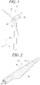
- FIG. 1 is a perspective view illustrating a wind turbine according to a first exemplary embodiment.
- the wind turbine 10 includes a tower 110, a nacelle 120, and a rotor 130.
- the wind turbine 10 may be installed on land or offshore, and may be a direct type with or without a gearbox.
- the tower 110 is installed standing up at a certain height on the ground or offshore, and supports the nacelle 120 and the rotor 130.
- the tower 110 may have a tubular shape that increases in diameter from top to bottom.
- the tower 110 may have a multistage form in which a plurality of tubular members are stacked.
- the inside of the tower 110 may be provided with a stair, a conveyor, or an elevator for transporting a worker or a work tool for maintenance.
- the nacelle 120 may be installed on the tower 110 to be able to yaw with respect to the tower 110.
- the nacelle 120 may be positioned on the tower 110 and rotatably coupled to the tower 110.
- the nacelle 120 may be a housing for accommodating a generator or the like, and may have a hexahedral shape.
- the shape of the nacelle 120 is not necessarily limited thereto, and the nacelle 120 may be formed in a cylinder, an ellipsoid, or the like.
- the rotor 130 includes a hub 131 and a plurality of blades 132, and the hub 131 is rotatably installed on a front surface of the nacelle 120.
- the plurality of blades 132 are coupled to an outer peripheral surface of the hub 131 while being spaced apart from each other at predetermined intervals in a circumferential direction.
- FIG. 1 illustrates that three blades 132 are installed on one hub 131, but the present disclosure is not limited thereto.
- the plurality of blades 132 are rotated about a central axis of the hub 131 by wind.
- Each of the blades 132 has a streamlined cross-section in a width direction, and a space may be formed therein.
- FIG. 2 is a perspective view illustrating one blade according to the first exemplary embodiment.
- FIG. 3 is a cross-sectional view of the blade according to the first exemplary embodiment.
- the blade 132 includes a cylindrical part connected to the hub 131 and has an airfoil cross-section outwardly.
- the blade 132 having an airfoil shape in cross-section includes a suction side S2 and a pressure side S1.
- the rotor 130 is rotated by the difference in pressure between the suction side S2 and the pressure side S1.
- the blade 132 includes a leading edge LE through which the wind enters and a trailing edge TE through which the wind exits.
- the blade 132 has a relatively flat extension adjacent to the leading edge LE and a large bend adjacent to the trailing edge TE.
- the blade 132 may include an outer skin 142, core panels 141, an inner skin 143, spar caps SC, and shear webs 155.
- the outer skin 142, the core panels 141, the inner skin 143, and the spar caps SC form a pressure side shell 181 and a suction side shell 182, and the pressure side shell 181 and suction side shell 182 are joined to form the blade 132.
- the core panels 141 are positioned between the inner skin 143 and the outer skin 142.
- the blade 132 may be in a form of a sandwich panel in which the inner skin 143 and the outer skin 142 surround the core panels 141 and the spar caps SC.
- the inner skin 143 and the outer skin 142 may be made of fiber-reinforced plastic (FRP).
- FRP fiber-reinforced plastic
- the inner skin 143 and the outer skin 142 may be made of glass-fiber-reinforced plastic (GFRP) or carbon-fiber-reinforced plastic (CFRP).
- the core panels 141 may be made of balsa wood or foam.
- the core panels 141 may be made of urethane foam.
- the core panels 141 may be disposed between the spar caps SC and outside the spar caps SC.
- the spar caps SC are respectively positioned between the core panels 141 to enhance the rigidity of the blade 132.
- Each of the spar caps SC may be in a form of a plate having a predetermined width extending in a longitudinal direction of the blade 132.
- the spar caps SC are spaced apart from each other in a thickness direction of the blade 132 and are installed on the pressure side S1 and the suction side S2.
- the shear webs 155 connect the spar caps SC installed on the pressure side S1 and the spar caps SC installed on the suction side S2, and are installed upright in the thickness direction of the blade 132.
- two shear webs 155 spaced apart from each other in the width direction of the blade 132 may be installed in the blade 132.
- the shear webs 155 may extend in the longitudinal direction of the blade 132.
- the shear web 155 disposed adjacent to the trailing edge TE has one end coupled to an associated spar cap SC including reinforcing fiber sheets 163 and the other end coupled to an associated spar cap SC including support plates 161.
- one shear web 155 may be coupled to the spar caps SC having different structures to support the blade 132.
- Each of the shear webs 155 may be in the form of a sandwich panel and may support a load by connecting the associated spar caps SC.
- the shear web 155 may have a structure in which a foam or wood is inserted between metal plates or fiber-reinforced plastic plates.
- FIG. 4 is a cross-sectional view illustrating a first spar cap according to the first exemplary embodiment.
- FIG. 5 is a cross-sectional view illustrating a second spar cap according to the first exemplary embodiment.
- FIG. 6 is a view illustrating a process of manufacturing the first spar cap according to the first exemplary embodiment.
- FIG. 7 is a view illustrating a process of manufacturing the second spar cap according to the first exemplary embodiment.
- FIG. 8 is a view illustrating a process of coupling the first and second spar caps to an outer skin according to the first exemplary embodiment.
- the blade 132 may include a first spar cap 151 positioned adjacent to the leading edge LE on the pressure side S1, a second spar cap 152 positioned adjacent to the trailing edge TE on the pressure side S1, a third spar cap 153 positioned adjacent to the leading edge LE on the suction side S2, and a fourth spar cap 154 positioned adjacent to the trailing edge TE on the suction side S2.
- first spar cap 151, the third spar cap 153, and the fourth spar cap 154 may be first-type spar caps each having a structure in which support plates 161 including reinforcing fibers are stacked, and the second spar cap 152 may be a second-type spar cap in which a resin is impregnated with reinforcing fiber sheets 163.
- the first spar cap 151 and the second spar cap 152 are spaced apart from each other on the pressure side S1, and the third spar cap 153 and the fourth spar cap 154 are spaced apart from each other on the suction side S2.
- One of the core panels 141 may be positioned between the first spar cap 151 and the second spar cap 152, and another core panel 141 may be positioned between the third spar cap 153 and the fourth spar cap 154.
- the first spar cap 151, the third spar cap 153, and the fourth spar cap 154 may each have a structure in which the support plates 161 including reinforcing fibers are stacked.
- the reinforcing fibers may be carbon fibers.
- the description of the first spar cap 151 will replace the description of the third spar cap 153 and the fourth spar cap 154.
- the first spar cap 151 may include support plates 161 and a resin bonding layer 162 for fixing the support plates 161.
- the resin bonding layer 162 may be made of a polyester resin, an epoxy resin, or the like.
- a detachable guide block 176 is installed at side ends of the support plates 161 in a state in which the support plates 161 are stacked on a mold 177.
- the resin stored in a container 175 is injected into the mold 177 to form a structure in which the support plates 161 are bonded by the resin bonding layer 162.
- Each of the support plates 161 may be an elongated plate formed by drawing a reinforcing fiber and a resin.
- the reinforcing fiber constituting the support plate 161 may be made of a carbon fiber.
- the strength of each spar cap SC can be improved because the spar cap SC is formed by stacking the support plates 161 including carbon fibers.
- the second spar cap 152 may include reinforcing fiber sheets 163 and a resin body 164 for supporting the reinforcing fiber sheets 163.
- the resin body 164 may be made of reinforcing-fiber-reinforced plastic.
- the reinforcing fiber may be a glass fiber.
- the resin body 164 surrounds and supports the reinforcing fiber sheets 163.
- the reinforcing fiber sheets 163 are wrapped with a film-type cover 171 in a state in which the reinforcing fiber sheets 163 are stacked on a mold 174.
- the resin stored in a container 172 is injected into the mold 174, and the air within the cover 171 is discharged by a vacuum pump 173. Accordingly, the reinforcing fiber sheets 163 are fixed inside the resin body 164 while preventing pores from being formed between the reinforcing fiber sheets 163.
- the second spar cap 152 may have a structure in which a polyester resin or an epoxy resin is impregnated with the reinforcing fiber sheets 163 so that the reinforcing fiber sheets 163 are integrally formed with the resin body 164.
- the spar caps 151, 152 and the core panels 141 are positioned on a main mold 178, the outer skin 142 is placed below them, and the inner skin 143 is placed above them.
- the outer skin 142 and the inner skin 143 may each be formed of a glass fiber sheet or a carbon fiber sheet.
- each of the outer skin 142 and the inner skin 143 may be formed of a hybrid fiber sheet including glass and carbon fibers.
- the inside of the cover 179 is connected to the vacuum pump 190 in a state in which the main mold 178 is wrapped with the film-type cover 179 to form a shell by injecting a resin while a vacuum pressure is applied to the space between the cover 179 and the main mold 178.
- the resin is injected, the resin is adhered to the outer skin 142 and the inner skin 143.
- the outer skin 142 and the inner skin 143 may be integrally fixed to the core panels 141 and the spar caps SC by the resin.
- the reinforcing fiber sheets 163 may easily reflect the bent shape and the twisted shape of the blade 132. However, it may be difficult for the support plates 161 to reflect the bent part of the blade 132 because the support plates 161 are relatively inflexible and are not easily bent.
- the degree of freedom in design of the blade 132 can be improved by freely forming the shape of the trailing edge TE.
- first spar cap 151 and the third spar cap 153 having a structure in which the support plates 161 are stacked are disposed in the side of the leading edge LE extending in a straight line receiving a relatively large load, the strength of the blade 132 can be improved.
- the fourth spar cap 154 in which the support plates 161 are stacked is disposed in the portion adjacent to the trailing edge TE on the suction side S2 which is relatively less bent compared to the pressure side S1, the strength of the blade 132 can be improved.
- FIG. 9 is a cross-sectional view of one blade according to the second exemplary embodiment.
- the blade 232 may include a first spar cap 251 positioned adjacent to a leading edge LE on a pressure side S1, a second spar cap 252 positioned adjacent to a trailing edge TE on the pressure side S1, a third spar cap 253 positioned adjacent to the leading edge LE on the suction side S2, and a fourth spar cap 254 positioned adjacent to the trailing edge TE on the suction side S2.
- first spar cap 251 and the third spar cap 253 may be first-type spar caps each having a structure in which support plates including reinforcing fibers are stacked
- second spar cap 252 and the fourth spar cap 254 may be second-type spar caps each having a structure in which a resin is impregnated with reinforcing fiber sheets.
- the first spar cap 251 and the second spar cap 252 are spaced apart from each other on the pressure side S1, and the third spar cap 253 and the fourth spar cap 254 are spaced apart from each other on the suction side S2.
- a core panel 141 may be positioned between the first spar cap 251 and the second spar cap 252, and another core panel 141 may be positioned between the third spar cap 253 and the fourth spar cap 254.
- the degree of freedom in design of the blade 232 can be improved by freely forming the shape of the trailing edge TE.
- the first spar cap 251 and the third spar cap 253 each having a structure in which the support plates including carbon fibers are stacked are disposed in the side of the leading edge LE extending in a straight line receiving a relatively large load, the strength of the blade 232 can be improved.
- FIG. 10 is a cross-sectional view illustrating a first spar cap according to the third exemplary embodiment.
- the blade according to the third exemplary embodiment has the same structure as the blade according to the first exemplary embodiment except for a first spar cap 351, a redundant description will be omitted.
- the first spar cap 351 may have a structure in which support plates 361 including carbon fibers are stacked.
- the first spar cap 351 may include support plates 361 and a resin bonding layer 362 for fixing the support plates 361.
- the outermost support plate 361 may have a smaller width W11 than the inner support plates 361.
- the first spar cap 351 is shaped to coincide with the outer surface of the blade curved in the form of an arc, the blade can be supported more stably.
- the freedom of design of the blade can be improved because some spar caps include the glass fiber sheets, and the strength of the blade can be improved because other spar caps have a structure in which the support plates including the carbon fibers are stacked.
Landscapes
- Engineering & Computer Science (AREA)
- Mechanical Engineering (AREA)
- Chemical & Material Sciences (AREA)
- Life Sciences & Earth Sciences (AREA)
- Sustainable Development (AREA)
- Sustainable Energy (AREA)
- Combustion & Propulsion (AREA)
- General Engineering & Computer Science (AREA)
- Composite Materials (AREA)
- Wind Motors (AREA)
Abstract
Description
- Apparatuses and methods consistent with exemplary embodiments relate to a wind turbine blade and a wind turbine including the same, and more particularly, to a wind turbine blade including a spar cap, and a wind turbine including the same.
- Wind power generation refers to a method for generating electric power by using a windmill to convert wind energy into mechanical energy (i.e., rotational force) and then driving a generator to obtain electrical energy.
- Wind power generation is being actively invested in the United States and Asia as well as in Europe, because wind power is the most economical renewable energy source developed so far and it is an indefinite, cost-free, and clean energy source that can be generated using wind.
- The wind turbine for wind power generation may be classified into a vertical-axis wind turbine and a horizontal-axis wind turbine according to the direction of the rotary shaft. For example, the horizontal-axis wind turbine has been mainly applied to commercial wind farms because the horizontal-axis wind turbine is more efficient and more stable than the vertical-axis wind turbine.
- The wind turbine includes a plurality of blades, and each blade is provided with a spar cap to improve its strength. The spar caps are respectively disposed at an upper portion (i.e., suction side) and a lower portion (i.e., pressure side) of the blade and are connected through a shear web.
- A plurality of spar caps may be installed in one blade. For example, four spar caps are installed between the core panels of the blade. Each spar cap must be bent and twisted according to the shape of the blade. However, the shape of the blade may be limited because it is difficult to bend or twist the spar cap depending on the constituent object. It is also necessary to prevent the formation of pores in the spar cap. If pores are formed in the spar cap, the strength of the spar cap may be decreased.
- Aspects of one or more exemplary embodiments provide a wind turbine blade capable of being easily manufactured while improving structural strength, and a wind turbine including the same.
- Additional aspects will be set forth in part in the description which follows and, in part, will become apparent from the description, or may be learned by practice of the exemplary embodiments.
- According to an aspect of an exemplary embodiment, there is provided a wind turbine blade including: an outer skin defining an external appearance, an inner skin spaced apart from the outer skin, a plurality of spar caps positioned between the outer skin and the inner skin and spaced apart from each other in a thickness direction of the blade, and shear webs configured to connect the plurality of spar caps, wherein at least one of the plurality of spar caps has a structure in which a resin is impregnated with reinforcing fiber sheets, and the other spar caps each have a structure in which support plates including reinforcing fibers are stacked.
- The spar cap including the reinforcing fiber sheets may be coupled to one end of an associated one of the shear webs.
- The spar caps each including the support plates may be coupled to the other ends of associated ones of the shear webs.
- The blade may have an airfoil cross-section and may include a pressure side, a suction side, a leading edge through which wind enters, and a trailing edge through which wind exits. The blade may include a first spar cap positioned adjacent to the leading edge on the pressure side, a second spar cap positioned adjacent to the trailing edge on the pressure side, a third spar cap positioned adjacent to the leading edge on the suction side, and a fourth spar cap positioned adjacent to the trailing edge on the suction side.
- The second spar cap may have a structure in which the resin is impregnated with the reinforcing fiber sheets.
- The first spar cap may have a structure in which the support plates including the reinforcing fibers are stacked.
- Each of the third spar cap and the fourth spar cap may have a structure in which the support plates including the reinforcing fibers are stacked.
- The support plates may be bonded through a resin bonding layer.
- Each of the second spar cap and the fourth spar cap may have a structure in which the resin is impregnated with the reinforcing fiber sheets.
- The support plates may be configured such that an outer support plate has a smaller width than an inner support plate.
- According to an aspect of another exemplary embodiment, there is provided a wind turbine including: a tower installed upright, a nacelle installed on the tower, and a rotor rotatably installed on the nacelle and including a plurality of blades. Each of the plurality of blades includes an outer skin defining an external appearance, an inner skin spaced apart from the outer skin, a plurality of spar caps positioned between the outer skin and the inner skin and spaced apart from each other in a thickness direction of the blade, and shear webs configured to connect the plurality of spar caps, wherein at least one of the plurality of spar caps has a structure in which a resin is impregnated with reinforcing fiber sheets, and the other spar caps each have a structure in which support plates including reinforcing fibers are stacked.
- The spar cap including the reinforcing fiber sheets may be coupled to one end of an associated one of the shear webs.
- The spar caps each including the support plates may be coupled to the other ends of associated ones of the shear webs.
- The blade may have an airfoil cross-section and may include a pressure side, a suction side, a leading edge through which wind enters, and a trailing edge through which wind exits. The blade may include a first spar cap positioned adjacent to the leading edge on the pressure side, a second spar cap positioned adjacent to the trailing edge on the pressure side, a third spar cap positioned adjacent to the leading edge on the suction side, and a fourth spar cap positioned adjacent to the trailing edge on the suction side.
- The second spar cap may have a structure in which the resin is impregnated with the reinforcing fiber sheets.
- The above and other aspects will become more apparent from the following description of the exemplary embodiments with reference to the accompanying drawings, in which:
-
FIG. 1 is a perspective view illustrating a wind turbine according to a first exemplary embodiment; -
FIG. 2 is a perspective view illustrating one blade according to the first exemplary embodiment; -
FIG. 3 is a cross-sectional view of the blade according to the first exemplary embodiment; -
FIG. 4 is a cross-sectional view illustrating a first spar cap according to the first exemplary embodiment; -
FIG. 5 is a cross-sectional view illustrating a second spar cap according to the first exemplary embodiment; -
FIG. 6 is a view illustrating a process of manufacturing the first spar cap according to the first exemplary embodiment; -
FIG. 7 is a view illustrating a process of manufacturing the second spar cap according to the first exemplary embodiment; -
FIG. 8 is a view illustrating a process of coupling the first and second spar caps to an outer skin according to the first exemplary embodiment; -
FIG. 9 is a cross-sectional view of one blade according to a second exemplary embodiment; and -
FIG. 10 is a cross-sectional view illustrating a first spar cap according to a third exemplary embodiment. - Various modifications and different embodiments will be described below in detail with reference to the accompanying drawings so that those skilled in the art can easily carry out the disclosure. It should be understood, however, that the present disclosure is not intended to be limited to the specific embodiments, but the present disclosure includes all modifications, equivalents or replacements that fall within the spirit and scope of the disclosure as defined in the following claims.
- The terminology used herein is for the purpose of describing specific embodiments only and is not intended to limit the scope of the disclosure. As used herein, the singular forms "a", "an" and "the" are intended to include the plural forms as well, unless the context clearly indicates otherwise. It will be further understood that the terms "comprises/includes" and/or "have/has" when used in this specification, specify the presence of stated features, integers, steps, operations, components, parts, and/or combinations thereof, but do not preclude the presence or addition of one or more of other features, integers, steps, operations, components, parts, and/or combinations thereof.
- Hereinafter, exemplary embodiments will be described with reference to the accompanying drawings. It should be noted that like reference numerals refer to like parts throughout various drawings and exemplary embodiments. In certain embodiments, a detailed description of functions and configurations well known in the art may be omitted to avoid obscuring appreciation of the disclosure by those skilled in the art. For the same reason, some components may be exaggerated, omitted, or schematically illustrated in the accompanying drawings.
-
FIG. 1 is a perspective view illustrating a wind turbine according to a first exemplary embodiment. - Referring to
FIG. 1 , thewind turbine 10 includes atower 110, anacelle 120, and arotor 130. Thewind turbine 10 may be installed on land or offshore, and may be a direct type with or without a gearbox. - The
tower 110 is installed standing up at a certain height on the ground or offshore, and supports thenacelle 120 and therotor 130. Thetower 110 may have a tubular shape that increases in diameter from top to bottom. In this case, thetower 110 may have a multistage form in which a plurality of tubular members are stacked. For example, the inside of thetower 110 may be provided with a stair, a conveyor, or an elevator for transporting a worker or a work tool for maintenance. - The
nacelle 120 may be installed on thetower 110 to be able to yaw with respect to thetower 110. In other words, thenacelle 120 may be positioned on thetower 110 and rotatably coupled to thetower 110. - The
nacelle 120 may be a housing for accommodating a generator or the like, and may have a hexahedral shape. However, the shape of thenacelle 120 is not necessarily limited thereto, and thenacelle 120 may be formed in a cylinder, an ellipsoid, or the like. - The
rotor 130 includes ahub 131 and a plurality ofblades 132, and thehub 131 is rotatably installed on a front surface of thenacelle 120. The plurality ofblades 132 are coupled to an outer peripheral surface of thehub 131 while being spaced apart from each other at predetermined intervals in a circumferential direction. AlthoughFIG. 1 illustrates that threeblades 132 are installed on onehub 131, but the present disclosure is not limited thereto. - The plurality of
blades 132 are rotated about a central axis of thehub 131 by wind. Each of theblades 132 has a streamlined cross-section in a width direction, and a space may be formed therein. -
FIG. 2 is a perspective view illustrating one blade according to the first exemplary embodiment.FIG. 3 is a cross-sectional view of the blade according to the first exemplary embodiment. - Referring to
FIGS. 2 and3 , theblade 132 includes a cylindrical part connected to thehub 131 and has an airfoil cross-section outwardly. - The
blade 132 having an airfoil shape in cross-section includes a suction side S2 and a pressure side S1. Therotor 130 is rotated by the difference in pressure between the suction side S2 and the pressure side S1. Theblade 132 includes a leading edge LE through which the wind enters and a trailing edge TE through which the wind exits. Theblade 132 has a relatively flat extension adjacent to the leading edge LE and a large bend adjacent to the trailing edge TE. - The
blade 132 may include anouter skin 142,core panels 141, aninner skin 143, spar caps SC, andshear webs 155. - The
outer skin 142, thecore panels 141, theinner skin 143, and the spar caps SC form apressure side shell 181 and asuction side shell 182, and thepressure side shell 181 andsuction side shell 182 are joined to form theblade 132. - The
core panels 141 are positioned between theinner skin 143 and theouter skin 142. Theblade 132 may be in a form of a sandwich panel in which theinner skin 143 and theouter skin 142 surround thecore panels 141 and the spar caps SC. - The
inner skin 143 and theouter skin 142 may be made of fiber-reinforced plastic (FRP). For example, theinner skin 143 and theouter skin 142 may be made of glass-fiber-reinforced plastic (GFRP) or carbon-fiber-reinforced plastic (CFRP). Thecore panels 141 may be made of balsa wood or foam. Thecore panels 141 may be made of urethane foam. Thecore panels 141 may be disposed between the spar caps SC and outside the spar caps SC. - The spar caps SC are respectively positioned between the
core panels 141 to enhance the rigidity of theblade 132. Each of the spar caps SC may be in a form of a plate having a predetermined width extending in a longitudinal direction of theblade 132. The spar caps SC are spaced apart from each other in a thickness direction of theblade 132 and are installed on the pressure side S1 and the suction side S2. - The
shear webs 155 connect the spar caps SC installed on the pressure side S1 and the spar caps SC installed on the suction side S2, and are installed upright in the thickness direction of theblade 132. For example, twoshear webs 155 spaced apart from each other in the width direction of theblade 132 may be installed in theblade 132. Theshear webs 155 may extend in the longitudinal direction of theblade 132. - The
shear web 155 disposed adjacent to the trailing edge TE has one end coupled to an associated spar cap SC including reinforcingfiber sheets 163 and the other end coupled to an associated spar cap SC includingsupport plates 161. As described above, according to the first exemplary embodiment, oneshear web 155 may be coupled to the spar caps SC having different structures to support theblade 132. - Each of the
shear webs 155 may be in the form of a sandwich panel and may support a load by connecting the associated spar caps SC. Theshear web 155 may have a structure in which a foam or wood is inserted between metal plates or fiber-reinforced plastic plates. -
FIG. 4 is a cross-sectional view illustrating a first spar cap according to the first exemplary embodiment.FIG. 5 is a cross-sectional view illustrating a second spar cap according to the first exemplary embodiment.FIG. 6 is a view illustrating a process of manufacturing the first spar cap according to the first exemplary embodiment.FIG. 7 is a view illustrating a process of manufacturing the second spar cap according to the first exemplary embodiment.FIG. 8 is a view illustrating a process of coupling the first and second spar caps to an outer skin according to the first exemplary embodiment. - Referring to
FIGS. 3 to 5 , theblade 132 may include afirst spar cap 151 positioned adjacent to the leading edge LE on the pressure side S1, asecond spar cap 152 positioned adjacent to the trailing edge TE on the pressure side S1, athird spar cap 153 positioned adjacent to the leading edge LE on the suction side S2, and afourth spar cap 154 positioned adjacent to the trailing edge TE on the suction side S2. - Here, the
first spar cap 151, thethird spar cap 153, and thefourth spar cap 154 may be first-type spar caps each having a structure in which supportplates 161 including reinforcing fibers are stacked, and thesecond spar cap 152 may be a second-type spar cap in which a resin is impregnated with reinforcingfiber sheets 163. - The
first spar cap 151 and thesecond spar cap 152 are spaced apart from each other on the pressure side S1, and thethird spar cap 153 and thefourth spar cap 154 are spaced apart from each other on the suction side S2. One of thecore panels 141 may be positioned between thefirst spar cap 151 and thesecond spar cap 152, and anothercore panel 141 may be positioned between thethird spar cap 153 and thefourth spar cap 154. - The
first spar cap 151, thethird spar cap 153, and thefourth spar cap 154 may each have a structure in which thesupport plates 161 including reinforcing fibers are stacked. Here, the reinforcing fibers may be carbon fibers. - Here, because the
third spar cap 153 and thefourth spar cap 154 have the same structure as thefirst spar cap 151, the description of thefirst spar cap 151 will replace the description of thethird spar cap 153 and thefourth spar cap 154. - The
first spar cap 151 may includesupport plates 161 and aresin bonding layer 162 for fixing thesupport plates 161. Theresin bonding layer 162 may be made of a polyester resin, an epoxy resin, or the like. - Referring to
FIG. 6 , adetachable guide block 176 is installed at side ends of thesupport plates 161 in a state in which thesupport plates 161 are stacked on amold 177. In this state, the resin stored in acontainer 175 is injected into themold 177 to form a structure in which thesupport plates 161 are bonded by theresin bonding layer 162. - Each of the
support plates 161 may be an elongated plate formed by drawing a reinforcing fiber and a resin. Here, the reinforcing fiber constituting thesupport plate 161 may be made of a carbon fiber. The strength of each spar cap SC can be improved because the spar cap SC is formed by stacking thesupport plates 161 including carbon fibers. - The
second spar cap 152 may include reinforcingfiber sheets 163 and aresin body 164 for supporting the reinforcingfiber sheets 163. Theresin body 164 may be made of reinforcing-fiber-reinforced plastic. Here, the reinforcing fiber may be a glass fiber. Theresin body 164 surrounds and supports the reinforcingfiber sheets 163. - Referring to
FIG. 7 , the reinforcingfiber sheets 163 are wrapped with a film-type cover 171 in a state in which the reinforcingfiber sheets 163 are stacked on amold 174. In this state, the resin stored in acontainer 172 is injected into themold 174, and the air within thecover 171 is discharged by avacuum pump 173. Accordingly, the reinforcingfiber sheets 163 are fixed inside theresin body 164 while preventing pores from being formed between the reinforcingfiber sheets 163. - The
second spar cap 152 may have a structure in which a polyester resin or an epoxy resin is impregnated with the reinforcingfiber sheets 163 so that the reinforcingfiber sheets 163 are integrally formed with theresin body 164. - Referring to
FIG. 8 , to form thepressure side shell 181 or thesuction side shell 182, the spar caps 151, 152 and thecore panels 141 are positioned on amain mold 178, theouter skin 142 is placed below them, and theinner skin 143 is placed above them. Theouter skin 142 and theinner skin 143 may each be formed of a glass fiber sheet or a carbon fiber sheet. Alternatively, each of theouter skin 142 and theinner skin 143 may be formed of a hybrid fiber sheet including glass and carbon fibers. - The inside of the
cover 179 is connected to thevacuum pump 190 in a state in which themain mold 178 is wrapped with the film-type cover 179 to form a shell by injecting a resin while a vacuum pressure is applied to the space between thecover 179 and themain mold 178. - If the resin is injected, the resin is adhered to the
outer skin 142 and theinner skin 143. In addition, theouter skin 142 and theinner skin 143 may be integrally fixed to thecore panels 141 and the spar caps SC by the resin. - Because the reinforcing
fiber sheets 163 have flexibility, the reinforcingfiber sheets 163 may easily reflect the bent shape and the twisted shape of theblade 132. However, it may be difficult for thesupport plates 161 to reflect the bent part of theblade 132 because thesupport plates 161 are relatively inflexible and are not easily bent. - According to the first exemplary embodiment, because the
second spar cap 152 formed by impregnating the resin with the reinforcingfiber sheets 163 is disposed adjacent to the trailing edge TE of the pressure side S1, the degree of freedom in design of theblade 132 can be improved by freely forming the shape of the trailing edge TE. - In addition, because the
first spar cap 151 and thethird spar cap 153 having a structure in which thesupport plates 161 are stacked are disposed in the side of the leading edge LE extending in a straight line receiving a relatively large load, the strength of theblade 132 can be improved. - Furthermore, because the
fourth spar cap 154 in which thesupport plates 161 are stacked is disposed in the portion adjacent to the trailing edge TE on the suction side S2 which is relatively less bent compared to the pressure side S1, the strength of theblade 132 can be improved. - Hereinafter, a blade according to a second exemplary embodiment will be described.
FIG. 9 is a cross-sectional view of one blade according to the second exemplary embodiment. - Referring to
FIG. 9 , theblade 232 may include afirst spar cap 251 positioned adjacent to a leading edge LE on a pressure side S1, asecond spar cap 252 positioned adjacent to a trailing edge TE on the pressure side S1, athird spar cap 253 positioned adjacent to the leading edge LE on the suction side S2, and afourth spar cap 254 positioned adjacent to the trailing edge TE on the suction side S2. - Here, the
first spar cap 251 and thethird spar cap 253 may be first-type spar caps each having a structure in which support plates including reinforcing fibers are stacked, and thesecond spar cap 252 and thefourth spar cap 254 may be second-type spar caps each having a structure in which a resin is impregnated with reinforcing fiber sheets. - The
first spar cap 251 and thesecond spar cap 252 are spaced apart from each other on the pressure side S1, and thethird spar cap 253 and thefourth spar cap 254 are spaced apart from each other on the suction side S2. Acore panel 141 may be positioned between thefirst spar cap 251 and thesecond spar cap 252, and anothercore panel 141 may be positioned between thethird spar cap 253 and thefourth spar cap 254. - According to the second exemplary embodiment, because the
second spar cap 252 and thefourth spar cap 254 each formed by impregnating a resin with glass fiber sheets are disposed adjacent to the trailing edge TE, the degree of freedom in design of theblade 232 can be improved by freely forming the shape of the trailing edge TE. In addition, because thefirst spar cap 251 and thethird spar cap 253 each having a structure in which the support plates including carbon fibers are stacked are disposed in the side of the leading edge LE extending in a straight line receiving a relatively large load, the strength of theblade 232 can be improved. - Hereinafter, a blade according to a third exemplary embodiment will be described.
FIG. 10 is a cross-sectional view illustrating a first spar cap according to the third exemplary embodiment. - Referring to
FIG. 10 , because the blade according to the third exemplary embodiment has the same structure as the blade according to the first exemplary embodiment except for afirst spar cap 351, a redundant description will be omitted. - The
first spar cap 351 may have a structure in which supportplates 361 including carbon fibers are stacked. Thefirst spar cap 351 may includesupport plates 361 and aresin bonding layer 362 for fixing thesupport plates 361. In thefirst spar cap 351, theoutermost support plate 361 may have a smaller width W11 than theinner support plates 361. - Accordingly, because the
first spar cap 351 is shaped to coincide with the outer surface of the blade curved in the form of an arc, the blade can be supported more stably. - As described above, according to the exemplary embodiments, the freedom of design of the blade can be improved because some spar caps include the glass fiber sheets, and the strength of the blade can be improved because other spar caps have a structure in which the support plates including the carbon fibers are stacked.
- While one or more exemplary embodiments have been described with reference to the accompanying drawings, it will be apparent to those skilled in the art that various variations and modifications may be made by adding, changing, or removing components without departing from the spirit and scope of the disclosure as defined in the appended claims, and these variations and modifications fall within the spirit and scope of the disclosure as defined in the appended claims.
Claims (15)
- A wind turbine blade (132) comprising:an outer skin (142) defining an external appearance;an inner skin (143) spaced apart from the outer skin (142);a plurality of spar caps (132) positioned between the outer skin (142) and the inner skin (143) and spaced apart from each other in a thickness direction of the blade (132); andshear webs (155) configured to connect the plurality of spar caps (132),wherein at least one of the plurality of spar caps (132) has a structure in which a resin is impregnated with reinforcing fiber sheets (163), and the other spar caps each have a structure in which support plates (161, 361) including reinforcing fibers are stacked.
- The wind turbine blade according to claim 1, wherein the spar cap (132) comprising the reinforcing fiber sheets (163) is coupled to one end of an associated one of the shear webs (155).
- The wind turbine blade according to claims 1 or 2, wherein the spar caps (132) each comprising the support plates (161, 361) are coupled to the other ends of associated ones of the shear webs (155).
- The wind turbine blade according to claim 1, wherein:the blade (132) has an airfoil cross-section and comprises a pressure side (S1), a suction side (S2), a leading edge (LE) through which wind enters, and a trailing edge (TE) through which wind exits; andthe blade (132) comprises a first spar cap (151, 251, 351) positioned adjacent to the leading edge (LE) on the pressure side (S1), a second spar cap (152, 252) positioned adjacent to the trailing edge (TE) on the pressure side (S1), a third spar cap (153, 253) positioned adjacent to the leading edge (LE) on the suction side (S2), and a fourth spar cap (154, 254) positioned adjacent to the trailing edge (TE) on the suction side (S2).
- The wind turbine blade according to claim 4, wherein the second spar cap (152, 252) has a structure in which the resin is impregnated with the reinforcing fiber sheets (163).
- The wind turbine blade according to claim 4, wherein the first spar cap (151, 251, 351) has a structure in which the support plates (161, 361) including the reinforcing fibers are stacked.
- The wind turbine blade according to claim 4, wherein each of the third spar cap (153, 253) and the fourth spar cap (154, 254) has a structure in which the support plates (161, 361) including the reinforcing fibers are stacked.
- The wind turbine blade according to any one of the preceding claims, wherein the support plates (161, 361) are bonded through a resin bonding layer.
- The wind turbine blade according to claim 4, wherein each of the second spar cap (152, 252) and the fourth spar cap (154, 254) has a structure in which the resin is impregnated with the reinforcing fiber sheets (163).
- The wind turbine blade according to claim 1, wherein the support plates (161, 361) are configured such that an outer support plate (161, 361) has a smaller width than an inner support plate (161, 361).
- A wind turbine (10) comprising:a tower (110) installed upright;a nacelle (120) installed on the tower (110); anda rotor (130) rotatably installed on the nacelle (120) and comprising a plurality of blades (132),wherein each of the plurality of blades (132) comprises:an outer skin (142) defining an external appearance;an inner skin (143) spaced apart from the outer skin (142);a plurality of spar caps positioned between the outer skin (142) and the inner skin (143) and spaced apart from each other in a thickness direction of the blade (132); andshear webs (155) configured to connect the plurality of spar caps (132),wherein at least one of the plurality of spar caps (132) has a structure in which a resin is impregnated with reinforcing fiber sheets (163), and the other spar caps each have a structure in which support plates (161, 361) including reinforcing fibers are stacked.
- The wind turbine according to claim 11, wherein the spar cap (132) comprising the reinforcing fiber sheets (163) is coupled to one end of an associated one of the shear webs (155).
- The wind turbine according to claim 12, wherein the spar caps each comprising the support plates (161, 361) are coupled to the other ends of associated ones of the shear webs (155).
- The wind turbine according to claim 11, wherein:the blade (132) has an airfoil cross-section and comprises a pressure side (S1), a suction side (S2), a leading edge (LE) through which wind enters, and a trailing edge (TE) through which wind exits; andthe blade (132) comprises a first spar cap (151, 251, 351) positioned adjacent to the leading edge (LE) on the pressure side (S1), a second spar cap (152, 252) positioned adjacent to the trailing edge (TE) on the pressure side (S1), a third spar cap (153, 253) positioned adjacent to the leading edge (LE) on the suction side (S2), and a fourth spar cap (154, 254) positioned adjacent to the trailing edge (TE) on the suction side (S2).
- The wind turbine according to claim 14, wherein the second spar cap (152, 252) has a structure in which the resin is impregnated with the reinforcing fiber sheets (163).
Applications Claiming Priority (1)
| Application Number | Priority Date | Filing Date | Title |
|---|---|---|---|
| KR1020210057987A KR102513583B1 (en) | 2021-05-04 | 2021-05-04 | Blade of wind turbine and manufacturing method of the same |
Publications (2)
| Publication Number | Publication Date |
|---|---|
| EP4086453A1 true EP4086453A1 (en) | 2022-11-09 |
| EP4086453B1 EP4086453B1 (en) | 2025-01-08 |
Family
ID=81326665
Family Applications (1)
| Application Number | Title | Priority Date | Filing Date |
|---|---|---|---|
| EP22168392.3A Active EP4086453B1 (en) | 2021-05-04 | 2022-04-14 | Wind turbine blade and wind turbine including the same |
Country Status (3)
| Country | Link |
|---|---|
| US (1) | US11754038B2 (en) |
| EP (1) | EP4086453B1 (en) |
| KR (2) | KR102513583B1 (en) |
Families Citing this family (2)
| Publication number | Priority date | Publication date | Assignee | Title |
|---|---|---|---|---|
| KR102719754B1 (en) | 2022-12-09 | 2024-10-22 | 두산에너빌리티 주식회사 | A blade of wind power generator |
| KR102724979B1 (en) * | 2022-12-16 | 2024-11-01 | 주식회사 자라윈드 | A fixing device for reinforcing ropes to maintain the soundness of wind turbine blades |
Citations (5)
| Publication number | Priority date | Publication date | Assignee | Title |
|---|---|---|---|---|
| EP2239461A2 (en) * | 2008-12-11 | 2010-10-13 | General Electric Company | Sparcap system for wind turbine rotor blade and method of fabricating wind turbine rotor blade |
| EP2791500A1 (en) * | 2011-12-16 | 2014-10-22 | Vestas Wind Systems A/S | Wind turbine blades |
| US20160040651A1 (en) * | 2014-08-07 | 2016-02-11 | General Electric Company | Methods of manufacturing rotor blades of a wind turbine |
| EP3174704A1 (en) * | 2014-07-31 | 2017-06-07 | Vestas Wind Systems A/S | Improvements relating to reinforcing structures for wind turbine blades |
| EP3501810A1 (en) * | 2017-12-22 | 2019-06-26 | Siemens Gamesa Renewable Energy A/S | Pultruded fibrous composite strips having corrugated profiles for wind turbine blade spar caps |
Family Cites Families (15)
| Publication number | Priority date | Publication date | Assignee | Title |
|---|---|---|---|---|
| JP4699255B2 (en) * | 2006-03-24 | 2011-06-08 | 三菱重工業株式会社 | Windmill wing |
| JP5078757B2 (en) | 2008-05-30 | 2012-11-21 | 三菱重工業株式会社 | Wind turbine blade and method for manufacturing wind turbine blade |
| DK2358998T3 (en) * | 2008-12-05 | 2017-10-30 | Vestas Wind Sys As | EFFICIENT WINDOWS, WINDOWS, AND ASSOCIATED SYSTEMS AND PROCEDURES FOR MANUFACTURING, INSTALLING AND USING |
| JP5546624B2 (en) * | 2011-12-09 | 2014-07-09 | 三菱重工業株式会社 | Windmill wing |
| JP5675673B2 (en) | 2012-02-29 | 2015-02-25 | 三菱重工業株式会社 | Fiber reinforced plastic heating element and wind power generator equipped with the heating element |
| EP2899396B1 (en) * | 2012-09-24 | 2017-08-16 | Mitsubishi Heavy Industries, Ltd. | Method for manufacturing windmill blade |
| US20160146185A1 (en) | 2014-11-25 | 2016-05-26 | General Electric Company | Methods for manufacturing a spar cap for a wind turbine rotor blade |
| JP2017129091A (en) | 2016-01-22 | 2017-07-27 | 株式会社日立製作所 | Wind power generator or blade manufacturing method |
| FR3063774B1 (en) * | 2017-03-13 | 2021-06-11 | Arkema France | THERMOPLASTIC POLYMER COMPOSITE WIND TURBINE BLADE, PART OF THE BLADE AND MANUFACTURING METHOD |
| JP2019218886A (en) | 2018-06-19 | 2019-12-26 | 株式会社日立製作所 | Windmill blade and wind power generation apparatus |
| JP2020084812A (en) | 2018-11-19 | 2020-06-04 | 株式会社日立製作所 | Windmill blade and wind power generation device |
| EP3726049B2 (en) | 2019-04-15 | 2026-04-01 | Siemens Gamesa Renewable Energy Innovation & Technology, S.L. | Rotor blade and method for manufacturing a rotor blade |
| EP3792049A1 (en) * | 2019-09-13 | 2021-03-17 | Siemens Gamesa Renewable Energy Innovation & Technology, S.L. | Wind turbine blade |
| KR102250535B1 (en) | 2020-01-20 | 2021-05-11 | 두산중공업 주식회사 | Blade of wind turbine and wind turbine including the same |
| KR102250536B1 (en) | 2020-01-20 | 2021-05-11 | 두산중공업 주식회사 | Blade of wind turbine and manufacturing method of the same |
-
2021
- 2021-05-04 KR KR1020210057987A patent/KR102513583B1/en active Active
-
2022
- 2022-04-14 US US17/720,326 patent/US11754038B2/en active Active
- 2022-04-14 EP EP22168392.3A patent/EP4086453B1/en active Active
-
2023
- 2023-03-20 KR KR1020230035774A patent/KR102586818B1/en active Active
Patent Citations (5)
| Publication number | Priority date | Publication date | Assignee | Title |
|---|---|---|---|---|
| EP2239461A2 (en) * | 2008-12-11 | 2010-10-13 | General Electric Company | Sparcap system for wind turbine rotor blade and method of fabricating wind turbine rotor blade |
| EP2791500A1 (en) * | 2011-12-16 | 2014-10-22 | Vestas Wind Systems A/S | Wind turbine blades |
| EP3174704A1 (en) * | 2014-07-31 | 2017-06-07 | Vestas Wind Systems A/S | Improvements relating to reinforcing structures for wind turbine blades |
| US20160040651A1 (en) * | 2014-08-07 | 2016-02-11 | General Electric Company | Methods of manufacturing rotor blades of a wind turbine |
| EP3501810A1 (en) * | 2017-12-22 | 2019-06-26 | Siemens Gamesa Renewable Energy A/S | Pultruded fibrous composite strips having corrugated profiles for wind turbine blade spar caps |
Also Published As
| Publication number | Publication date |
|---|---|
| KR20230041999A (en) | 2023-03-27 |
| KR102513583B1 (en) | 2023-03-22 |
| KR20220150695A (en) | 2022-11-11 |
| KR102586818B1 (en) | 2023-10-06 |
| EP4086453B1 (en) | 2025-01-08 |
| US20220356864A1 (en) | 2022-11-10 |
| US11754038B2 (en) | 2023-09-12 |
Similar Documents
| Publication | Publication Date | Title |
|---|---|---|
| EP2204577B1 (en) | Flatback insert for turbine blades | |
| US9951750B2 (en) | Rotor blade with interior shelf for a flat plate spar cap | |
| EP2249027B1 (en) | Segmented wind turbine blades | |
| US8142164B2 (en) | Rotor blade for use with a wind turbine and method for assembling rotor blade | |
| US8172539B2 (en) | Wind turbine rotor blade joint | |
| US11754038B2 (en) | Wind turbine blade and wind turbine including the same | |
| US12064933B2 (en) | Wind turbine blade | |
| KR102250536B1 (en) | Blade of wind turbine and manufacturing method of the same | |
| CN101670635A (en) | Molded reinforced shear web cores | |
| EP4086452A1 (en) | Method of manufacturing wind turbine blade | |
| EP3894689B1 (en) | Segmented rotor blade having maximized overall pre-bend via an increased pre-bend in a blade tip segment thereof | |
| KR102250535B1 (en) | Blade of wind turbine and wind turbine including the same | |
| EP3899245B1 (en) | Wind turbine rotor blade shell with varying fiber types | |
| CN113167217B (en) | Bonded rotor blade with internal support structure having different fiber orientations for pin reinforcement | |
| EP4388192B1 (en) | Winged spar cap configuration for a jointed wind turbine blade | |
| JP2023004899A (en) | Wind turbine blade | |
| US20160177918A1 (en) | Wind turbine rotor blades with support flanges | |
| EP4311930A1 (en) | First blade segment for a segmented wind turbine rotor blade | |
| WO2011144970A1 (en) | Aerogenerator blade and method of manufacturing thereof |
Legal Events
| Date | Code | Title | Description |
|---|---|---|---|
| PUAI | Public reference made under article 153(3) epc to a published international application that has entered the european phase |
Free format text: ORIGINAL CODE: 0009012 |
|
| STAA | Information on the status of an ep patent application or granted ep patent |
Free format text: STATUS: REQUEST FOR EXAMINATION WAS MADE |
|
| 17P | Request for examination filed |
Effective date: 20220414 |
|
| AK | Designated contracting states |
Kind code of ref document: A1 Designated state(s): AL AT BE BG CH CY CZ DE DK EE ES FI FR GB GR HR HU IE IS IT LI LT LU LV MC MK MT NL NO PL PT RO RS SE SI SK SM TR |
|
| RBV | Designated contracting states (corrected) |
Designated state(s): AL AT BE BG CH CY CZ DE DK EE ES FI FR GB GR HR HU IE IS IT LI LT LU LV MC MK MT NL NO PL PT RO RS SE SI SK SM TR |
|
| STAA | Information on the status of an ep patent application or granted ep patent |
Free format text: STATUS: EXAMINATION IS IN PROGRESS |
|
| 17Q | First examination report despatched |
Effective date: 20230619 |
|
| GRAP | Despatch of communication of intention to grant a patent |
Free format text: ORIGINAL CODE: EPIDOSNIGR1 |
|
| STAA | Information on the status of an ep patent application or granted ep patent |
Free format text: STATUS: GRANT OF PATENT IS INTENDED |
|
| INTG | Intention to grant announced |
Effective date: 20241028 |
|
| GRAS | Grant fee paid |
Free format text: ORIGINAL CODE: EPIDOSNIGR3 |
|
| GRAA | (expected) grant |
Free format text: ORIGINAL CODE: 0009210 |
|
| STAA | Information on the status of an ep patent application or granted ep patent |
Free format text: STATUS: THE PATENT HAS BEEN GRANTED |
|
| AK | Designated contracting states |
Kind code of ref document: B1 Designated state(s): AL AT BE BG CH CY CZ DE DK EE ES FI FR GB GR HR HU IE IS IT LI LT LU LV MC MK MT NL NO PL PT RO RS SE SI SK SM TR |
|
| REG | Reference to a national code |
Ref country code: GB Ref legal event code: FG4D |
|
| REG | Reference to a national code |
Ref country code: CH Ref legal event code: EP |
|
| REG | Reference to a national code |
Ref country code: DE Ref legal event code: R096 Ref document number: 602022009483 Country of ref document: DE |
|
| REG | Reference to a national code |
Ref country code: IE Ref legal event code: FG4D |
|
| REG | Reference to a national code |
Ref country code: LT Ref legal event code: MG9D |
|
| REG | Reference to a national code |
Ref country code: NL Ref legal event code: MP Effective date: 20250108 |
|
| REG | Reference to a national code |
Ref country code: AT Ref legal event code: MK05 Ref document number: 1758476 Country of ref document: AT Kind code of ref document: T Effective date: 20250108 |
|
| PG25 | Lapsed in a contracting state [announced via postgrant information from national office to epo] |
Ref country code: NL Free format text: LAPSE BECAUSE OF FAILURE TO SUBMIT A TRANSLATION OF THE DESCRIPTION OR TO PAY THE FEE WITHIN THE PRESCRIBED TIME-LIMIT Effective date: 20250108 |
|
| PG25 | Lapsed in a contracting state [announced via postgrant information from national office to epo] |
Ref country code: RS Free format text: LAPSE BECAUSE OF FAILURE TO SUBMIT A TRANSLATION OF THE DESCRIPTION OR TO PAY THE FEE WITHIN THE PRESCRIBED TIME-LIMIT Effective date: 20250408 |
|
| PG25 | Lapsed in a contracting state [announced via postgrant information from national office to epo] |
Ref country code: PL Free format text: LAPSE BECAUSE OF FAILURE TO SUBMIT A TRANSLATION OF THE DESCRIPTION OR TO PAY THE FEE WITHIN THE PRESCRIBED TIME-LIMIT Effective date: 20250108 |
|
| PGFP | Annual fee paid to national office [announced via postgrant information from national office to epo] |
Ref country code: DE Payment date: 20250409 Year of fee payment: 4 |
|
| PG25 | Lapsed in a contracting state [announced via postgrant information from national office to epo] |
Ref country code: ES Free format text: LAPSE BECAUSE OF FAILURE TO SUBMIT A TRANSLATION OF THE DESCRIPTION OR TO PAY THE FEE WITHIN THE PRESCRIBED TIME-LIMIT Effective date: 20250108 |
|
| PG25 | Lapsed in a contracting state [announced via postgrant information from national office to epo] |
Ref country code: IS Free format text: LAPSE BECAUSE OF FAILURE TO SUBMIT A TRANSLATION OF THE DESCRIPTION OR TO PAY THE FEE WITHIN THE PRESCRIBED TIME-LIMIT Effective date: 20250508 Ref country code: NO Free format text: LAPSE BECAUSE OF FAILURE TO SUBMIT A TRANSLATION OF THE DESCRIPTION OR TO PAY THE FEE WITHIN THE PRESCRIBED TIME-LIMIT Effective date: 20250408 |
|
| PG25 | Lapsed in a contracting state [announced via postgrant information from national office to epo] |
Ref country code: HR Free format text: LAPSE BECAUSE OF FAILURE TO SUBMIT A TRANSLATION OF THE DESCRIPTION OR TO PAY THE FEE WITHIN THE PRESCRIBED TIME-LIMIT Effective date: 20250108 |
|
| PG25 | Lapsed in a contracting state [announced via postgrant information from national office to epo] |
Ref country code: LV Free format text: LAPSE BECAUSE OF FAILURE TO SUBMIT A TRANSLATION OF THE DESCRIPTION OR TO PAY THE FEE WITHIN THE PRESCRIBED TIME-LIMIT Effective date: 20250108 Ref country code: PT Free format text: LAPSE BECAUSE OF FAILURE TO SUBMIT A TRANSLATION OF THE DESCRIPTION OR TO PAY THE FEE WITHIN THE PRESCRIBED TIME-LIMIT Effective date: 20250508 |
|
| PG25 | Lapsed in a contracting state [announced via postgrant information from national office to epo] |
Ref country code: BG Free format text: LAPSE BECAUSE OF FAILURE TO SUBMIT A TRANSLATION OF THE DESCRIPTION OR TO PAY THE FEE WITHIN THE PRESCRIBED TIME-LIMIT Effective date: 20250108 Ref country code: GR Free format text: LAPSE BECAUSE OF FAILURE TO SUBMIT A TRANSLATION OF THE DESCRIPTION OR TO PAY THE FEE WITHIN THE PRESCRIBED TIME-LIMIT Effective date: 20250409 |
|
| PG25 | Lapsed in a contracting state [announced via postgrant information from national office to epo] |
Ref country code: AT Free format text: LAPSE BECAUSE OF FAILURE TO SUBMIT A TRANSLATION OF THE DESCRIPTION OR TO PAY THE FEE WITHIN THE PRESCRIBED TIME-LIMIT Effective date: 20250108 |
|
| PG25 | Lapsed in a contracting state [announced via postgrant information from national office to epo] |
Ref country code: SE Free format text: LAPSE BECAUSE OF FAILURE TO SUBMIT A TRANSLATION OF THE DESCRIPTION OR TO PAY THE FEE WITHIN THE PRESCRIBED TIME-LIMIT Effective date: 20250108 |
|
| PG25 | Lapsed in a contracting state [announced via postgrant information from national office to epo] |
Ref country code: SM Free format text: LAPSE BECAUSE OF FAILURE TO SUBMIT A TRANSLATION OF THE DESCRIPTION OR TO PAY THE FEE WITHIN THE PRESCRIBED TIME-LIMIT Effective date: 20250108 |
|
| REG | Reference to a national code |
Ref country code: DE Ref legal event code: R097 Ref document number: 602022009483 Country of ref document: DE |
|
| PG25 | Lapsed in a contracting state [announced via postgrant information from national office to epo] |
Ref country code: DK Free format text: LAPSE BECAUSE OF FAILURE TO SUBMIT A TRANSLATION OF THE DESCRIPTION OR TO PAY THE FEE WITHIN THE PRESCRIBED TIME-LIMIT Effective date: 20250108 |
|
| PG25 | Lapsed in a contracting state [announced via postgrant information from national office to epo] |
Ref country code: EE Free format text: LAPSE BECAUSE OF FAILURE TO SUBMIT A TRANSLATION OF THE DESCRIPTION OR TO PAY THE FEE WITHIN THE PRESCRIBED TIME-LIMIT Effective date: 20250108 Ref country code: CZ Free format text: LAPSE BECAUSE OF FAILURE TO SUBMIT A TRANSLATION OF THE DESCRIPTION OR TO PAY THE FEE WITHIN THE PRESCRIBED TIME-LIMIT Effective date: 20250108 |
|
| PG25 | Lapsed in a contracting state [announced via postgrant information from national office to epo] |
Ref country code: RO Free format text: LAPSE BECAUSE OF FAILURE TO SUBMIT A TRANSLATION OF THE DESCRIPTION OR TO PAY THE FEE WITHIN THE PRESCRIBED TIME-LIMIT Effective date: 20250108 |
|
| PG25 | Lapsed in a contracting state [announced via postgrant information from national office to epo] |
Ref country code: SK Free format text: LAPSE BECAUSE OF FAILURE TO SUBMIT A TRANSLATION OF THE DESCRIPTION OR TO PAY THE FEE WITHIN THE PRESCRIBED TIME-LIMIT Effective date: 20250108 |
|
| PLBE | No opposition filed within time limit |
Free format text: ORIGINAL CODE: 0009261 |
|
| STAA | Information on the status of an ep patent application or granted ep patent |
Free format text: STATUS: NO OPPOSITION FILED WITHIN TIME LIMIT |
|
| REG | Reference to a national code |
Ref country code: CH Ref legal event code: L10 Free format text: ST27 STATUS EVENT CODE: U-0-0-L10-L00 (AS PROVIDED BY THE NATIONAL OFFICE) Effective date: 20251119 |
|
| REG | Reference to a national code |
Ref country code: CH Ref legal event code: H13 Free format text: ST27 STATUS EVENT CODE: U-0-0-H10-H13 (AS PROVIDED BY THE NATIONAL OFFICE) Effective date: 20251125 |
|
| PG25 | Lapsed in a contracting state [announced via postgrant information from national office to epo] |
Ref country code: LU Free format text: LAPSE BECAUSE OF NON-PAYMENT OF DUE FEES Effective date: 20250414 |
|
| 26N | No opposition filed |
Effective date: 20251009 |
|
| PG25 | Lapsed in a contracting state [announced via postgrant information from national office to epo] |
Ref country code: MC Free format text: LAPSE BECAUSE OF FAILURE TO SUBMIT A TRANSLATION OF THE DESCRIPTION OR TO PAY THE FEE WITHIN THE PRESCRIBED TIME-LIMIT Effective date: 20250108 |
|
| REG | Reference to a national code |
Ref country code: BE Ref legal event code: MM Effective date: 20250430 |
|
| PG25 | Lapsed in a contracting state [announced via postgrant information from national office to epo] |
Ref country code: BE Free format text: LAPSE BECAUSE OF NON-PAYMENT OF DUE FEES Effective date: 20250430 |
|
| PG25 | Lapsed in a contracting state [announced via postgrant information from national office to epo] |
Ref country code: CH Free format text: LAPSE BECAUSE OF NON-PAYMENT OF DUE FEES Effective date: 20250430 |
|
| PG25 | Lapsed in a contracting state [announced via postgrant information from national office to epo] |
Ref country code: IT Free format text: LAPSE BECAUSE OF FAILURE TO SUBMIT A TRANSLATION OF THE DESCRIPTION OR TO PAY THE FEE WITHIN THE PRESCRIBED TIME-LIMIT Effective date: 20250108 |
|
| PGFP | Annual fee paid to national office [announced via postgrant information from national office to epo] |
Ref country code: GB Payment date: 20260303 Year of fee payment: 5 |
|
| PG25 | Lapsed in a contracting state [announced via postgrant information from national office to epo] |
Ref country code: IE Free format text: LAPSE BECAUSE OF NON-PAYMENT OF DUE FEES Effective date: 20250414 |
|
| PGFP | Annual fee paid to national office [announced via postgrant information from national office to epo] |
Ref country code: FR Payment date: 20260223 Year of fee payment: 5 |