EP4086333B1 - Vollautomatische genanalysevorrichtung und genanalyseverfahren - Google Patents
Vollautomatische genanalysevorrichtung und genanalyseverfahren Download PDFInfo
- Publication number
- EP4086333B1 EP4086333B1 EP21920108.4A EP21920108A EP4086333B1 EP 4086333 B1 EP4086333 B1 EP 4086333B1 EP 21920108 A EP21920108 A EP 21920108A EP 4086333 B1 EP4086333 B1 EP 4086333B1
- Authority
- EP
- European Patent Office
- Prior art keywords
- pcr
- tube
- clamping
- opening
- centrifugal
- Prior art date
- Legal status (The legal status is an assumption and is not a legal conclusion. Google has not performed a legal analysis and makes no representation as to the accuracy of the status listed.)
- Active
Links
Images


Classifications
-
- B—PERFORMING OPERATIONS; TRANSPORTING
- B67—OPENING, CLOSING OR CLEANING BOTTLES, JARS OR SIMILAR CONTAINERS; LIQUID HANDLING
- B67B—APPLYING CLOSURE MEMBERS TO BOTTLES JARS, OR SIMILAR CONTAINERS; OPENING CLOSED CONTAINERS
- B67B3/00—Closing bottles, jars or similar containers by applying caps
-
- B—PERFORMING OPERATIONS; TRANSPORTING
- B04—CENTRIFUGAL APPARATUS OR MACHINES FOR CARRYING-OUT PHYSICAL OR CHEMICAL PROCESSES
- B04B—CENTRIFUGES
- B04B11/00—Feeding, charging, or discharging bowls
- B04B11/04—Periodical feeding or discharging; Control arrangements therefor
-
- B—PERFORMING OPERATIONS; TRANSPORTING
- B04—CENTRIFUGAL APPARATUS OR MACHINES FOR CARRYING-OUT PHYSICAL OR CHEMICAL PROCESSES
- B04B—CENTRIFUGES
- B04B5/00—Other centrifuges
- B04B5/04—Radial chamber apparatus for separating predominantly liquid mixtures, e.g. butyrometers
- B04B5/0407—Radial chamber apparatus for separating predominantly liquid mixtures, e.g. butyrometers for liquids contained in receptacles
- B04B5/0414—Radial chamber apparatus for separating predominantly liquid mixtures, e.g. butyrometers for liquids contained in receptacles comprising test tubes
-
- B—PERFORMING OPERATIONS; TRANSPORTING
- B67—OPENING, CLOSING OR CLEANING BOTTLES, JARS OR SIMILAR CONTAINERS; LIQUID HANDLING
- B67B—APPLYING CLOSURE MEMBERS TO BOTTLES JARS, OR SIMILAR CONTAINERS; OPENING CLOSED CONTAINERS
- B67B3/00—Closing bottles, jars or similar containers by applying caps
- B67B3/20—Closing bottles, jars or similar containers by applying caps by applying and rotating preformed threaded caps
-
- B—PERFORMING OPERATIONS; TRANSPORTING
- B67—OPENING, CLOSING OR CLEANING BOTTLES, JARS OR SIMILAR CONTAINERS; LIQUID HANDLING
- B67B—APPLYING CLOSURE MEMBERS TO BOTTLES JARS, OR SIMILAR CONTAINERS; OPENING CLOSED CONTAINERS
- B67B7/00—Hand- or power-operated devices for opening closed containers
- B67B7/02—Hand- or power-operated devices for opening closed containers for removing stoppers
-
- B—PERFORMING OPERATIONS; TRANSPORTING
- B67—OPENING, CLOSING OR CLEANING BOTTLES, JARS OR SIMILAR CONTAINERS; LIQUID HANDLING
- B67B—APPLYING CLOSURE MEMBERS TO BOTTLES JARS, OR SIMILAR CONTAINERS; OPENING CLOSED CONTAINERS
- B67B7/00—Hand- or power-operated devices for opening closed containers
- B67B7/14—Hand- or power-operated devices for opening closed containers for removing tightly-fitting lids or covers, e.g. of shoe-polish tins, by gripping and rotating
-
- C—CHEMISTRY; METALLURGY
- C12—BIOCHEMISTRY; BEER; SPIRITS; WINE; VINEGAR; MICROBIOLOGY; ENZYMOLOGY; MUTATION OR GENETIC ENGINEERING
- C12Q—MEASURING OR TESTING PROCESSES INVOLVING ENZYMES, NUCLEIC ACIDS OR MICROORGANISMS; COMPOSITIONS OR TEST PAPERS THEREFOR; PROCESSES OF PREPARING SUCH COMPOSITIONS; CONDITION-RESPONSIVE CONTROL IN MICROBIOLOGICAL OR ENZYMOLOGICAL PROCESSES
- C12Q1/00—Measuring or testing processes involving enzymes, nucleic acids or microorganisms; Compositions therefor; Processes of preparing such compositions
- C12Q1/68—Measuring or testing processes involving enzymes, nucleic acids or microorganisms; Compositions therefor; Processes of preparing such compositions involving nucleic acids
- C12Q1/6806—Preparing nucleic acids for analysis, e.g. for polymerase chain reaction [PCR] assay
-
- G—PHYSICS
- G01—MEASURING; TESTING
- G01N—INVESTIGATING OR ANALYSING MATERIALS BY DETERMINING THEIR CHEMICAL OR PHYSICAL PROPERTIES
- G01N35/00—Automatic analysis not limited to methods or materials provided for in any single one of groups G01N1/00 - G01N33/00; Handling materials therefor
- G01N35/0099—Automatic analysis not limited to methods or materials provided for in any single one of groups G01N1/00 - G01N33/00; Handling materials therefor comprising robots or similar manipulators
-
- G—PHYSICS
- G01—MEASURING; TESTING
- G01N—INVESTIGATING OR ANALYSING MATERIALS BY DETERMINING THEIR CHEMICAL OR PHYSICAL PROPERTIES
- G01N35/00—Automatic analysis not limited to methods or materials provided for in any single one of groups G01N1/00 - G01N33/00; Handling materials therefor
- G01N35/02—Automatic analysis not limited to methods or materials provided for in any single one of groups G01N1/00 - G01N33/00; Handling materials therefor using a plurality of sample containers moved by a conveyor system past one or more treatment or analysis stations
- G01N35/04—Details of the conveyor system
-
- G—PHYSICS
- G01—MEASURING; TESTING
- G01N—INVESTIGATING OR ANALYSING MATERIALS BY DETERMINING THEIR CHEMICAL OR PHYSICAL PROPERTIES
- G01N35/00—Automatic analysis not limited to methods or materials provided for in any single one of groups G01N1/00 - G01N33/00; Handling materials therefor
- G01N35/10—Devices for transferring samples or any liquids to, in, or from, the analysis apparatus, e.g. suction devices, injection devices
- G01N35/1009—Characterised by arrangements for controlling the aspiration or dispense of liquids
- G01N35/1016—Control of the volume dispensed or introduced
-
- B—PERFORMING OPERATIONS; TRANSPORTING
- B04—CENTRIFUGAL APPARATUS OR MACHINES FOR CARRYING-OUT PHYSICAL OR CHEMICAL PROCESSES
- B04B—CENTRIFUGES
- B04B11/00—Feeding, charging, or discharging bowls
- B04B11/04—Periodical feeding or discharging; Control arrangements therefor
- B04B2011/046—Loading, unloading, manipulating sample containers
-
- G—PHYSICS
- G01—MEASURING; TESTING
- G01N—INVESTIGATING OR ANALYSING MATERIALS BY DETERMINING THEIR CHEMICAL OR PHYSICAL PROPERTIES
- G01N35/00—Automatic analysis not limited to methods or materials provided for in any single one of groups G01N1/00 - G01N33/00; Handling materials therefor
- G01N2035/00465—Separating and mixing arrangements
- G01N2035/00495—Centrifuges
-
- G—PHYSICS
- G01—MEASURING; TESTING
- G01N—INVESTIGATING OR ANALYSING MATERIALS BY DETERMINING THEIR CHEMICAL OR PHYSICAL PROPERTIES
- G01N35/00—Automatic analysis not limited to methods or materials provided for in any single one of groups G01N1/00 - G01N33/00; Handling materials therefor
- G01N35/02—Automatic analysis not limited to methods or materials provided for in any single one of groups G01N1/00 - G01N33/00; Handling materials therefor using a plurality of sample containers moved by a conveyor system past one or more treatment or analysis stations
- G01N35/04—Details of the conveyor system
- G01N2035/0401—Sample carriers, cuvettes or reaction vessels
- G01N2035/0403—Sample carriers with closing or sealing means
- G01N2035/0405—Sample carriers with closing or sealing means manipulating closing or opening means, e.g. stoppers, screw caps, lids or covers
-
- G—PHYSICS
- G01—MEASURING; TESTING
- G01N—INVESTIGATING OR ANALYSING MATERIALS BY DETERMINING THEIR CHEMICAL OR PHYSICAL PROPERTIES
- G01N35/00—Automatic analysis not limited to methods or materials provided for in any single one of groups G01N1/00 - G01N33/00; Handling materials therefor
- G01N35/10—Devices for transferring samples or any liquids to, in, or from, the analysis apparatus, e.g. suction devices, injection devices
- G01N2035/1027—General features of the devices
- G01N2035/1048—General features of the devices using the transfer device for another function
- G01N2035/1051—General features of the devices using the transfer device for another function for transporting containers, e.g. retained by friction
Definitions
- the present disclosure relates to the field of medical detection technologies, and particularly to a full-automatic gene analysis apparatus and a gene analysis method.
- test tube lid opening and closing device can only achieve automatic lid opening and closing function which is single, and cannot complete operations after the lid is opened and closed.
- the present disclosure provides a full-automatic gene analysis apparatus to solve problems that an existing detection apparatus requires a large detection space, wastes labor and has a low detection efficiency.
- the present disclosure provides a full-automatic gene analysis apparatus which has a specific technical solution as defined in claim 1.
- the PCR buffer region may be provided across the nucleic acid purification region and the PCR detection region, the PCR buffer region may be a sealed chamber, and the sealed chamber may be provided with a first opening located in the nucleic acid purification region and a second opening located in the PCR detection region; the first opening may be provided with a first door for opening and closing the first opening, and the second opening may be provided with a second door for opening and closing the second opening; the centrifugal transfer device and the second lid opening and closing device may be both located within the sealed chamber and may be located below the first opening and the second opening.
- the full-automatic gene analysis apparatus may further include a negative pressure suction device and an air treatment device, the negative pressure suction device may be respectively communicated with the PCR detection region and the air treatment device, the air treatment device may be communicated with outside atmosphere.
- the negative pressure suction device is configured to provide a negative pressure effect such that a gas pressure of the nucleic acid purification region is greater than that of the PCR buffer region, and a gas pressure of the PCR buffer region is greater than that of the PCR detection region.
- the air treatment device may include an air filter, a reagent solution filter and an exhaust pipe, and the negative pressure suction device, the air filter, the reagent solution filter and the exhaust pipe may be communicated sequentially.
- a one-way valve may be provided between the sealed chamber and the PCR detection region for allowing a unidirectional gas stream flow from the sealed chamber to the PCR detection region.
- the first taking and placing device may include a motion mechanism and a first clamping mechanism connected to each other, and the motion mechanism may be configured to drive the first clamping mechanism to translate and lift and drop;
- the first clamping mechanism may include two clamping arms, each clamping arm may be provided with a first clamping structure and a second clamping structure, the two first clamping structures are fitted to form a first clamping portion, and the two second clamping structures are fitted to form a second clamping portion.
- the first clamping structure may be an arc groove formed in an inner side of the clamping arm, and/or the second clamping structure may be a clamping block provided at a lower end of the clamping arm.
- the first taking and placing device may further include a pipetting device configured to perform a pipetting operation after a pipette tip is taken.
- the PCR detection device may include a plurality of PCR detection mechanisms, the plurality of PCR detection mechanisms may be sequentially arranged in a preset direction, the second taking and placing device may be configured to sequentially place the PCR tubes into the plurality of PCR detection mechanisms.
- the full-automatic gene analysis apparatus is configured for performing detection after all hole positions of the PCR detection mechanisms have been loaded with the PCR tubes.
- the centrifugal transfer device may further include a tube body fixing assembly; a motor base plate may be provided at a bottom of the rotary driving member, a fixing base plate may be provided on the side of the motor base plate away from the rotary driving member, and the second lid opening and closing device and the tube body fixing assembly may be both provided on the fixing base plate; the tube body fixing assembly has a tube body clamp for clamping the PCR tube.
- the tube body fixing assembly may include a clamping driving member, a clamping screw and a clamping nut; the clamping driving member may be in transmission connection with the clamping screw, the clamping nut may be provided on the clamping screw, the clamping nut is connected with the tube body clamp, and the clamping driving member may be configured to drive the clamping screw to rotate in an axis direction of the clamping screw, so as to move the tube body clamp towards or away from the PCR tube.
- the tube body fixing assembly may further include a clamping mounting frame; the clamping driving member is connected with the clamping mounting frame, and the clamping mounting frame may be provided with a limiting signal sensor and an origin signal sensor.
- the centrifugal transfer device may further include an outer housing, an upper cover plate and a rear cover plate; the upper cover plate and the rear cover plate may be both connected with the outer housing, the fixing base plate is respectively connected with the outer housing and the rear cover plate, the fixing base plate, the upper cover plate, the rear cover plate and the outer housing form an accommodating cavity, and the second lid opening and closing device may be located in the accommodating cavity.
- an upper cover sealing strip may be provided between the outer housing and the upper cover plate; the fixing base plate may be provided with a lower sealing strip; a first sealing strip may be provided between the rear cover plate and the outer housing; an inner frame may be provided in the accommodating cavity, and a second sealing strip may be provided between the inner frame and the outer housing.
- the centrifugal transfer device may further include a door opening and closing assembly; the upper cover plate may be provided with an opening, the door opening and closing assembly may have a door pressing plate, the opening may be plugged by the door pressing plate, and a door-plate sealing strip is provided between the door opening and closing assembly and the upper cover plate.
- the door opening and closing assembly may include a linear motor, a door frame, a first spring hanger, a second spring hanger and an elastic member;
- the linear motor may be provided on the upper cover plate, the linear motor is in transmission connection with the door frame, the first spring hanger may be provided on the door frame, a kidney shape hole may be provided in the door frame, and the door pressing plate extends into the kidney shape hole through the second spring hanger; one end of the elastic member may be connected with the first spring hanger, the other end of the elastic member may be connected with the second spring hanger, and the elastic member may be configured to give the door pressing plate a tendency to move towards the door frame.
- the upper cover plate may be provided with a limiting block; the linear motor drives the door frame to move towards the limiting block, such that the door pressing plate abuts against the limiting block, and the door pressing plate moves along the kidney shape hole to tightly press the door-plate sealing strip.
- the centrifugal transfer device in the present disclosure may include: the rotary disc, the second lid opening and closing device and the rotary driving member; the rotary disc is configured to mount the PCR tube, the second lid opening and closing device has the grabbing portion, and the grabbing portion can drive the tube lid on the PCR tube to move; the rotary driving member is in transmission connection with the rotary disc, and the rotary driving member has the rotary mode and the centrifugal mode; when in the rotary mode, the rotary driving member drives the PCR tube to move to the position below the grabbing portion; when in the centrifugal mode, the rotary driving member drives the PCR tube to perform centrifugal motion.
- the PCR tube is placed on the rotary disc, the rotary mode of the rotary driving member is started, the PCR tube is moved to the position below the grabbing portion, and the tube lid on the PCR tube is driven to move by the grabbing portion of the second lid opening and closing device, so as to complete a lid opening or closing operation;
- the centrifugal mode of the rotary driving member is started, and the rotary disc rotates at a high speed to drive the PCR tube to perform centrifugal motion, thus facilitating a centrifugal operation of reagents in the PCR tube;
- the lid opening and closing functions can be achieved, the reagents may be centrifuged, more functions are achieved, and the technical problem that in a prior art, an existing PCR tube lid opening and closing device can only achieve the single automatic lid opening and closing functions is solved.
- the present disclosure further provides a gene analysis method in which the above apparatus is applied, including the following steps:
- the first taking and placing device is configured to take and place the sample tube or the PCR tube or perform the pipetting operation, the lid is automatically opened and closed by the lid opening and closing device, and then, the genes may be purified and extracted automatically, thus automatically constructing a PCR system; automatic transfer and centrifuging operations of the PCR tube are realized by the centrifugal transfer device, thus achieving plural purposes with one device; the PCR detection step is automatically performed by the second taking and placing device and the PCR detection device, and manual intervention is avoided in the whole process, thus improving a detection efficiency, guaranteeing detection accuracy, simplifying a required experimental apparatus, and reducing the space for detection.
- the terms “provided”, “mounted”, “connected”, and “coupled” and the like are used broadly, and may be, for example, fixed connections, detachable connections, or integral connections; may also be mechanical or electrical connections; may also be direct connections or indirect connections via intervening structures; may also be inner communications of two elements.
- the above terms can be understood by those skilled in the art according to specific situations.
- an exemplary embodiment of the present disclosure particularly proposes a full-automatic gene analysis apparatus intended to achieve full automation of gene analysis detection through linkage of various functional devices.
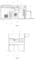
- the full-automatic gene analysis apparatus may include a body 100, a first taking and placing device 200 (shown in FIG. 19 ), a second taking and placing device (not shown), a first lid opening and closing device 300, a second lid opening and closing device 400, a sample rack 500, a consumable rack 600, a PCR detection device 700, a centrifugal transfer device 800, and other functional devices, and it should be noted that FIG. 1 in the exemplary embodiment of the present disclosure only shows a part of an upper structure of the apparatus, and does not show the first taking and placing device 200 and other parts in the present embodiment.
- the body 100 in the exemplary embodiment of the present disclosure may be used as a mounting base for other functional devices, and may have a structure similar to a multi-layer box in the drawing, or may be in other structural forms, and a bottom of the body 100 may be provided with a traveling mechanism, such as a roller, or the like, to facilitate movement of the whole apparatus.
- a traveling mechanism such as a roller, or the like
- An upper portion of the body 100 in the exemplary embodiment of the present disclosure may be divided by a partition into a nucleic acid purification region 110 and a PCR detection region 120 isolated from each other, the body may be provided with a PCR buffer region spanning the nucleic acid purification region 110 and the PCR detection region 120, a nucleic acid purification module 180 and a template buffer module may be provided in the nucleic acid purification region 110 in the present embodiment, and the nucleic acid purification module 180 may be configured to place a nucleic acid extraction tool, such as a reagent strip (not shown), or the like.
- a nucleic acid extraction tool such as a reagent strip (not shown), or the like.
- a lower portion of the body 100 in the exemplary embodiment of the present disclosure may be provided with a spare consumable placing region 140 and a waste tip collecting region 150, the spare consumable placing region 140 may be configured to place spare consumables, and the waste tip collecting region 150 may be configured to store waste pipette tips used in a detection process.
- the first taking and placing device 200, the first lid opening and closing device 300, the sample rack 500 and the consumable rack 600 in the exemplary embodiment of the present disclosure may all be mounted in the nucleic acid purification region 110, the first taking and placing device 200 in the exemplary embodiment of the present disclosure may be moved or operated to the nucleic acid purification module 180, the sample rack 500, the consumable rack 600, the first lid opening and closing device 300 and the centrifugal transfer device 800, and take and place detection objects, such as the sample tube 900, or the like, and the detection objects include the sample tube 900, the PCR tube 1000, various pipette tips, or the like.
- the first lid opening and closing device 300 in the exemplary embodiment of the present disclosure may be configured to open or close a tube lid of the sample tube 900
- the sample rack 500 in the exemplary embodiment of the present disclosure is configured to store the sample tube 900
- the consumable rack 600 in the exemplary embodiment of the present disclosure is configured to store the PCR tube 1000, reagents, various pipette tips, or the like.
- the PCR detection device 700 and the second taking and placing device in the exemplary embodiment of the present disclosure may be both mounted in the PCR detection region 120, and the second taking and placing device in the exemplary embodiment of the present disclosure may be moved to the centrifugal transfer device 800 and the PCR detection device 700 and take and place the PCR tube, and has a similar function and structure to the first taking and placing device 200 in the exemplary embodiment of the present disclosure.
- the centrifugal transfer device 800 in the exemplary embodiment of the present disclosure may have one part located in the nucleic acid purification region 110 and the other part located in the PCR detection region 120, the centrifugal transfer device 800 may be configured to perform centrifugal treatment on the PCR tube 1000, and using position characteristics and structural characteristics of the centrifugal transfer device 800, the centrifugal transfer device 800 may rotate to drive the PCR tube 1000 thereon to move from the nucleic acid purification region 110 to the PCR detection region 120, thereby simplifying a structure and integrating centrifugation and transfer functions.
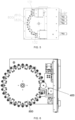
- the centrifugal transfer device 800 in the exemplary embodiment of the present disclosure may structurally include a rotary disc 810 and a plurality of mounting assemblies 820 hinged near an edge of the rotary disc 810, the mounting assembly 820 may be configured to fix and contain the PCR tube 1000, and during centrifugal rotation of the rotary disc 810, since the mounting assembly 820 may further rotate centrifugally under a centrifugal force, an efficiency and effect of centrifuging the PCR tube 1000 can be improved.
- the rotary disc 810 may be a rotary circular disc.
- the centrifugal transfer device 800 may include: a rotary disc 810, a second lid opening and closing device 400 and a rotary driving member 3.
- the rotary disc 810 may be configured to mount the PCR tube 1000, the second lid opening and closing device 400 may have a grabbing portion 7, and the grabbing portion 7 can drive the tube lid on the PCR tube 1000 to move;
- the rotary driving member 3 may be in transmission connection with the rotary disc 810, and the rotary driving member 3 may have a rotary mode and a centrifugal mode; when in the rotary mode, the rotary driving member 3 may drive the PCR tube 1000 to move to a position below the grabbing portion 7; and when in the centrifugal mode, the rotary driving member 3 may drive the PCR tube 1000 to perform centrifugal motion.
- the PCR tube 1000 may be placed on the rotary disc 810, and a number of the PCR tubes 1000 may be one or more.
- An origin trigger may be provided on the rotary disc 810
- an origin position signal sensor may be provided on the rotary driving member 3
- the rotary driving member 3 drives the rotary disc 810 to rotate, and when the origin trigger is rotated to a position of the origin position signal sensor, the origin position signal sensor senses the origin trigger, the rotary disc 810 stops rotating, and this position serves as a position origin;
- each PCR tube 1000 on the rotary disc 810 is rotated to a tube placing position of a moving mechanical arm with this position as a reference and stops, and in conjunction with hole positions on the rotary disc 810, a clamping jaw on the moving mechanical arm automatically loads all the hole positions with the PCR tubes 1000 or places a required number of PCR tubes 1000 on the hole positions of the rotary disc 810, and a pipetting device on the moving mechanical arm adds the required reagent or sample into the PCR tube 1000 with the lid opened, for example, adds a PCR reagent and a DNA or RNA template into the PCR tube 1000 with the
- the rotary disc 810 When the rotary driving member 3 is switched to the rotary mode, the rotary disc 810 is driven to rotate, such that the PCR tube 1000 is moved to a position below the grabbing portion 7, thus facilitating the grabbing portion 7 to open or close the tube lid of the PCR tube 1000; when the rotary driving member 3 is switched to the centrifugal mode, the rotary disc 810 is driven to rotate at a high speed, and the PCR tube 1000 performs centrifugal motion, thus facilitating a centrifugal operation of the reagent.
- the centrifugal transfer device 800 may include: the rotary disc 810, the second lid opening and closing device 400 and the rotary driving member 3; the rotary disc 810 may be configured to mount the PCR tube 1000, the second lid opening and closing device 400 may have the grabbing portion 7, and the grabbing portion 7 can drive the tube lid on the PCR tube 1000 to move; the rotary driving member 3 is in transmission connection with the rotary disc 810, and the rotary driving member 3 may have the rotary mode and the centrifugal mode; when in the rotary mode, the rotary driving member 3 may drive the PCR tube 1000 to move to the position below the grabbing portion 7; when in the centrifugal mode, the rotary driving member 3 may drive the PCR tube 1000 to perform centrifugal motion.
- the PCR tube 1000 is placed on the rotary disc 810, the rotary mode of the rotary driving member 3 is started, the PCR tube 1000 is moved to the position below the grabbing portion 7, and the tube lid on the PCR tube 1000 is driven to move by the grabbing portion 7 of the second lid opening and closing device 400, so as to complete a lid opening or closing operation; the centrifugal mode of the rotary driving member 3 is started, and the rotary disc 810 rotates at a high speed to drive the PCR tube 1000 to perform centrifugal motion, thus facilitating the centrifugal operation of the reagents in the PCR tube 1000; and lid opening and closing functions can be achieved, the reagents may be centrifuged, more functions are achieved, and the technical problem that in a prior art, an existing PCR tube 1000 lid opening and closing device can only achieve single automatic lid opening and closing functions is solved.
- the centrifugal transfer device 800 includes a mounting assembly 820, and the mounting assembly 820 may be a hanging basket.
- the PCR tube 1000 is placed in the hanging basket; a plurality of hanging baskets are provided, the plural hanging baskets are uniformly arranged in an outer circumference direction of the rotary disc 810, and the hanging baskets are hinged to the rotary disc 810; a tube lid placing portion 6 is provided between any two adjacent hanging baskets.
- sample tube placing holes in the rotary disc 810 are uniformly distributed in the rotary disc 810, the rotary disc 810 may be fixedly connected with the rotary driving member 3 by a connecting piece, the hanging baskets may be uniformly distributed and mounted on the rotary disc 810, the hanging baskets may swing flexibly, the tube lid placing portion 6 may be provided between any two hanging baskets, the tube lid placing portions 6 and the hanging baskets are alternately and uniformly distributed and mounted on the rotary disc 810, and the unscrewed tube lid is placed on the tube lid placing portion; in addition, the tube lid placing portion 6 may not be provided, if there exists only one PCR tube 1000, the tube lid may be always grabbed by the grabbing portion 7 without placement of the tube lid, and whether the tube lid placing portion 6 is provided is selected according to actual conditions; and the rotary driving member 3 moves to position each hole position with a reference that the origin trigger triggers the origin position signal sensor, and meanwhile, the rotary driving member 3 also achieves a high-speed rotary centr
- the PCR tube 1000 may be placed in the hanging basket, and the hanging basket may be connected with the rotary disc 810 by a rotating shaft; when the rotary disc 810 does not rotate, the hanging basket is kept perpendicular to a surface of the rotary disc 810 under the action of gravity, and at this point, the sample, the PCR tube 1000 and the tube lid may be taken and placed conveniently; during centrifugation, an included angle between the hanging basket and the rotary disc 810 becomes smaller under the action of a centrifugal force, such that the reagent or sample in the PCR tube 1000 may be conveniently centrifuged to a bottom of the tube.
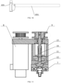
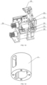
- the second lid opening and closing device 400 may include a gripper driving member 8, a connecting screw 9, a nut sleeve 10, a moving seat 11 and a wedge 12; the gripper driving member 8 may be in transmission connection with the connecting screw 9, the nut sleeve 10 may be provided on the connecting screw 9, the nut sleeve 10 may be connected with the wedge 12 through the moving seat 11, and the gripper driving member 8 may be configured to drive the connecting screw 9 to rotate in an axis direction of the connecting screw, so as to move the nut sleeve 10, the moving seat 11 and the wedge 12 in the axis direction of the connecting screw 9; the wedge 12 may have an inclined surface, the grabbing portion 7 may abut against the inclined surface, and the wedge 12 moves to drive the grabbing portion 7 to clamp or release the tube lid.
- the gripper driving member 8 may be a driving motor, a first belt pulley may be provided on an output shaft of the driving motor, a second belt pulley may be provided at an end of the connecting screw 9, and transmission of the first belt pulley and the second belt pulley may be implemented by a belt;
- the nut sleeve 10 may be in threaded connection with the connecting screw 9, the gripper driving member 8 drives the connecting screw 9 to rotate, the moving seat 11 and the wedge 12 connected with the nut sleeve 10 linearly move along the connecting screw 9, the nut sleeve 10 linearly moves back and forth by forward and reverse rotation of the connecting screw 9, and the wedge 12 is fixedly connected with the moving seat 11 by a connecting piece, such that the wedge 12 linearly moves back and forth;
- the inclined surface is provided on the wedge 12,
- the grabbing portion 7 specifically includes two fingers, corresponding inclined surfaces are provided on the fingers, and the inclined surface of the wedge 12 is matched with the corresponding inclined surfaces of the two fingers, thereby driving the two
- the second lid opening and closing device 400 may further include a lifting driving member 13, a fixing mounting plate 14 and a fixing seat 15;
- the fixing seat 15 may be connected with the fixing mounting plate 14, a sliding groove may be provided in the fixing seat 15, the connecting screw 9 may penetrate through the fixing seat 15 into the sliding groove, and the nut sleeve 10 may be located in the sliding groove;
- the lifting driving member 13 may be connected with the fixing mounting plate 14, and the lifting driving member 13 may be configured to drive the fixing mounting plate 14 to move, so as to move the grabbing portion 7 towards or away from the PCR tube 1000.
- the lifting driving member 13 may be mounted on a lifting mounting frame, a sliding rail is provided on the lifting mounting frame, the fixing mounting plate 14 may be slidably connected with the sliding rail, the origin position signal sensor may be provided on the lifting mounting frame, a signal trigger may be provided on the fixing mounting plate 14, and the lifting driving member 13 moves up and down to drive the grabbing portion 7 to move up and down, so as to separate and combine the tube lid and a tube body; the lifting driving member 13 moves with a reference that the signal trigger triggers the origin position signal sensor.
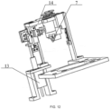
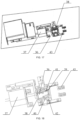
- the centrifugal transfer device 800 may further include a tube body fixing assembly 16 (shown in FIG. 7 ); a motor base plate 17 may be provided at a bottom of the rotary driving member 3, a fixing base plate 18 may be provided on the side of the motor base plate 17 away from the rotary driving member 3, and the second lid opening and closing device 400 and the tube body fixing assembly 16 may be both provided on the fixing base plate 18, as shown in FIG. 8 ; the tube body fixing assembly 16 may have a tube body clamp 19 (shown in FIG. 13 ) for clamping the PCR tube 1000.
- the fixing base plate 18 and the motor base plate 17 may be connected by a support, such that the fixing base plate 18 supports the motor base plate 17, the tube body fixing assembly 16 may be provided beside the rotary disc 810, and the tube body clamp 19 may clamp the PCR tube 1000 when the lid is opened, thereby avoiding that the PCR tube 1000 is inseparable from the tube lid due to too tight connection therebetween.
- the tube body fixing assembly 16 may include a clamping driving member 20, a clamping screw 21 and a clamping nut 22; the clamping driving member 20 may be in transmission connection with the clamping screw 21, the clamping nut 22 is provided on the clamping screw 21, the clamping nut 22 is connected with the tube body clamp 19, and the clamping driving member 20 may be configured to drive the clamping screw 21 to rotate in an axis direction of the clamping screw, so as to move the tube body clamp 19 towards or away from the PCR tube 1000.
- a belt pulley may be provided at a driving end of the clamping driving member 20, and a belt pulley is also provided at an end of the clamping screw 21, such that the clamping driving member 20 drives the clamping screw 21 to rotate by cooperation of the two belt pulleys, so as to further drive the clamping nut 22 and the tube body clamp 19 connected with the clamping nut 22 to move back and forth, thereby fixing and releasing the tube body.
- the tube body fixing assembly 16 may further include a clamping mounting frame 23; the clamping driving member 20 may be connected with the clamping mounting frame 23, and the clamping mounting frame 23 may be provided with a limiting signal sensor 24 and an origin signal sensor 25.
- a guide rail may be provided on the clamping mounting frame 23, the tube body clamp 19 may move along the guide rail, a trigger may be provided on the tube body clamp 19, and the tube body clamp 19 moves with the trigger and trigger positions of the limiting signal sensor 24 and the origin signal sensor 25 as references, such that the tube body clamp 19 can only move between the limiting signal sensor 24 and the origin signal sensor 25.
- a lid opening working process is as follows: the PCR tube 1000 is placed in the mounting assembly 820, such as the hanging basket, on the rotary disc 810, the rotary mode of the rotary driving member 3 is started, the rotary disc 810 rotates to move the PCR tube 1000 to the position below the grabbing portion 7, the lifting driving member 13 drives the grabbing portion 7 to move towards the PCR tube 1000, the clamping driving member 20 drives the tube body clamp 19 to move towards the PCR tube 1000, and the tube body of the PCR tube 1000 is clamped by the tube body clamp 19; the gripper driving member 8 drives the connecting screw 9 to rotate, so as to open the two grippers of the grabbing portion 7, and after the two grippers move to the position of the tube lid, the gripper driving member 8 drives the connecting screw 9 to rotate reversely, the two grippers of the grabbing portion 7 get close to each other to clamp the tube lid, and the lifting driving member 13 drives the grabbing portion 7 to move away from the PCR tube 1000 to separate the tube lid from the tube body, thus
- a specific lid closing working process is as follows: after the grabbing portion 7 grabs the tube lid, the lifting driving member 13 drives the grabbing portion 7 to move towards the tube body, the tube lid extends to the tube body, the gripper driving member 8 drives the connecting screw 9 to rotate, and the two grippers of the grabbing portion 7 get away from each other to release the tube lid, thus completing the lid closing operation.
- the lids may be opened and closed continuously or individually.
- the centrifugal mode of the rotary driving member 3 is started, the rotary disc 810 rotates at a high speed to swing the hanging basket, and the reagent in the tube body of the PCR tube 1000 performs centrifugal motion to finish the centrifugal operation.
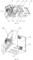
- the centrifugal transfer device 800 may further include an outer housing 26, an upper cover plate 27 and a rear cover plate 28; the upper cover plate 27 and the rear cover plate 28 may be both connected with the outer housing 26, the fixing base plate 18 may be connected with the outer housing 26 and the rear cover plate 28, the fixing base plate 18, the upper cover plate 27, the rear cover plate 28 and the outer housing 26 enclose an accommodating cavity, and the second lid opening and closing device 400 may be located in the accommodating cavity.
- the accommodating cavity enclosed by the fixing base plate 18, the upper cover plate 27, the rear cover plate 28 and the outer housing 26 packages the second lid opening and closing device 400, the rotary disc 810, the rotary driving member 3 and the tube body fixing assembly 16 and isolates them from the outside.
- an upper cover sealing strip 29 may be provided between the outer housing 26 and the upper cover plate 27; the fixing base plate 18 may be provided with a lower sealing strip 30; a first sealing strip 31 may be provided between the rear cover plate 28 and the outer housing 26; an inner frame 32 may be provided in the accommodating cavity, and a second sealing strip 33 is provided between the inner frame 32 and the outer housing 26.
- the lower sealing strip 30 may be mounted on the fixing base plate 18, and the outer housing 26 may be connected with the fixing base plate 18, such that the outer housing 26 tightly presses the lower sealing strip 30 to seal a lower portion;
- the upper cover sealing strip 29 may be mounted on the outer housing 26, and the upper cover plate 27 may be connected with the outer housing 26, such that the upper cover sealing strip 29 is pressed tightly to seal an upper portion;
- the inner frame 32 may be connected with the outer housing 26, such that the second sealing strip 33 is pressed tightly to seal a side surface;
- the rear cover plate 28 may be connected with the outer housing 26 and the fixing base plate 18, such that the first sealing strip 31 and the lower sealing strip 30 are pressed tightly to seal a rear surface.
- the centrifugal transfer device 800 may further include a door opening and closing assembly 35; the upper cover plate 27 may be provided with an opening, the door opening and closing assembly 35 may be provided with a door pressing plate 36, the opening may be plugged by the door pressing plate 36, and a door-plate sealing strip 34 is provided between the door opening and closing assembly 35 and the upper cover plate 27.
- a plurality of door opening and closing assemblies 35 may be provided, the door opening and closing assemblies 35 are provided in one-to-one correspondence to the openings and the door-plate sealing strips 34, and the door-plate sealing strips 34 may be mounted on the upper cover plate 27.
- the door opening and closing assembly 35 may include a linear motor 37, a door frame 38, a first spring hanger 39, a second spring hanger 40 and an elastic member 41;
- the linear motor 37 may be provided on the upper cover plate 27, the linear motor 37 may be in transmission connection with the door frame 38, the first spring hanger 39 may be provided on the door frame 38, a kidney shape hole 42 may be provided in the door frame 38, and the door pressing plate 36 may extend into the kidney shape hole 42 through the second spring hanger 40; one end of the elastic member 41 may be connected with the first spring hanger 39, the other end of the elastic member 41 may be connected with the second spring hanger 40, and the elastic member 41 may be configured to give the door pressing plate 36 a tendency to move towards the door frame 38.
- a first door enclosure and a second door enclosure may be provided on the upper cover plate 27, a motor mounting base is mounted on the upper cover plate 27, the linear motor 37 is mounted on the motor mounting base, a guide rail assembly is mounted on the upper cover plate 27, the door frame 38 is mounted on a slider of the guide rail assembly through a support, the first spring hanger 39 is mounted on the door frame 38, the door pressing plate 36 is connected with the second spring hanger 40, shafts at two ends of the second spring hanger 40 may be inserted into the kidney shape holes 42 of the door frame 38, hooks at two ends of the elastic member 41 are hooked on the first spring hanger 39 and the second spring hanger 40 to hang the door pressing plate 36 in the kidney shape hole 42 for movement, a screw of the linear motor 37 is connected with the door frame 38, a trigger sensing device is connected with the door frame 38, a first sensor and a second sensor may be fixed on the upper cover plate 27, and the second door enclosure may be fixed on the support and the slider
- the upper cover plate 27 may be provided with a limiting block 43; the linear motor 37 drives the door frame 38 to move towards the limiting block 43, such that the door pressing plate 36 abuts against the limiting block 43, and the door pressing plate 36 moves along the kidney shape hole 42 to tightly press the door-plate sealing strip 34.
- the linear motor 37 is activated, and the screw of the linear motor 37 moves linearly forwards, such that the door frame 38 slides on the guide rail assembly; when the door pressing plate 36 contacts the limiting block 43 and the linear motor 37 moves forwards, an assembly of the door pressing plate 36 and the second spring hanger 40 may slide in the door frame 38 along the kidney shape hole 42, and move downwards in a vertical direction, so as to press a door sealing strip downwards, thereby achieving a door sealing purpose; when the linear motor 37 moves backwards, the door frame 38 moves backwards along the guide rail assembly, and at this point, the assembly of the door pressing plate 36 and the second spring hanger 40 moves upward under a pulling force of the elastic member, such that the door pressing plate 36 is separated from the door-plate sealing strip 34, the opening of the upper cover plate 27 is opened, and meanwhile, the second door enclosure always moves with the door frame 38.
- the arrangement of the sealing strips between the outer housing and the cover plates of the centrifugal transfer device 800 may achieve an integral sealing effect of the centrifugal transfer device 800, such that the internal reagent or sample may be prevented from polluting the outside.
- a door sealing effect may be further achieved, such that the internal reagent or sample may be further prevented from polluting the outside.
- a specific method to which the full-automatic gene analysis apparatus according to the exemplary embodiment of the present disclosure is applied may include specific steps of nucleic acid extraction, PCR system construction, centrifugal treatment, PCR detection, or the like; the nucleic acid extraction step in the exemplary embodiment of the present disclosure may include: the first taking and placing device 200 (shown in FIG.
- the PCR system construction step S2 in the exemplary embodiment of the present disclosure may include: the first taking and placing device 200 transfers the PCR tube 1000 on the consumable rack 600 to the centrifugal transfer device 800, the PCR tube lid is opened by the second lid opening and closing device 400, and the first taking and placing device 200 then takes a second pipette tip on the consumable rack 600, allows the second pipette tip to suck a reagent, adds the reagent into the PCR tube 1000, then takes a third pipette tip on the consumable rack 600, allows the third pipette tip to suck a gene sample extracted in the nucleic acid purification module 180, and adds the gene sample into the PCR tube 1000.
- the centrifugal treatment step in the exemplary embodiment of the present disclosure may include: the PCR tube lid is closed by the second lid opening and closing device 400, and then, the centrifugal transfer device 800 performs rotary centrifugal treatment on the PCR tube 1000 and transfers the PCR tube 1000 after the centrifugal treatment to the PCR detection region 120.
- the PCR detection step in the exemplary embodiment of the present disclosure may include: the second taking and placing device transfers the PCR tube 1000 located in the PCR detection region 120 to the PCR detection device 700 for detection.
- the sample tube 900 filled with the sample is required to be placed on the sample rack 500; in specific work, the first taking and placing device 200 first grabs the sample tube 900 on the sample rack 500 to the first lid opening and closing device 300 for the lid opening operation; after the lid of the sample tube 900 is opened, the first taking and placing device 200 in the exemplary embodiment of the present disclosure is moved to a pipette tip region of the consumable rack 600 to take the first pipette tip, is then moved to the sample tube 900 with the lid opened by the first lid opening and closing device 300 again, allows the first pipette tip to suck the sample in the sample tube 900, is then moved to a position above a middle part of the reagent strip of the nucleic acid purification module 180, drops the sample sucked in the first pipette tip into the reagent strip, and then discards the first pipette tip to the waste tip collecting region.
- the first lid opening and closing device 300 again closes the sample tube lid, and then, the first taking and placing device 200 places the sample tube 900 with the sample tube lid closed by the first lid opening and closing device 300 back again into the sample rack 500.
- the first taking and placing device 200 in the exemplary embodiment of the present disclosure grabs the PCR tube 1000 in a PCR tube region in the consumable rack 600 to the centrifugal transfer device 800, the PCR tube lid is opened by the second lid opening and closing device 400, and then, the first taking and placing device 200 is moved to the consumable rack 600 again to take the second pipette tip, adds the reagent into the PCR tube 1000 with the lid opened on the centrifugal transfer device after the reagent is sucked in a reagent region of the consumable rack 600, and then discards the second pipette tip.
- the first taking and placing device 200 may be moved to the consumable rack 600 again to take the third pipette tip, and is then moved to the nucleic acid purification module 180, an appropriate quantity of extracted DNA or RNA templates are sucked and added into the reagent-added PCR tube 1000 with the lid opened on the centrifugal transfer device 800, and then, the third pipette tip is discarded; or the first taking and placing device 200 is directly moved to the nucleic acid purification module 180 after taking the third pipette tip, all the DNA or RNA templates extracted by the nucleic acid purification module 180 are sucked, an appropriate quantity of DNA or RNA templates are added into the reagent-added PCR tube 1000 with the lid opened, and the remaining DNA or RNA templates are transferred to a template buffer tube of the template buffer region for later use; then, the lid of the PCR tube is closed by the second lid opening and closing device 400.
- a centrifugal transfer module performs rotary centrifugation, and the reagent, and the DNA or RNA template in the PCR tube 1000 are centrifuged to the bottom of the test tube; after the centrifugation by the PCR tube 1000 is completed, the centrifugal transfer device 800 in the exemplary embodiment of the present disclosure is rotated by a certain angle, and the PCR tube 1000 thereon is transferred to the PCR detection region 120.
- the second taking and placing device in the PCR detection region 120 may move, to the PCR detection device 700, the PCR tube 1000 on the centrifugal transfer device 800 transferred into the PCR detection region 120, the PCR detection device 700 includes a plurality of PCR detection mechanisms, and the plurality of PCR detection mechanisms are sequentially arranged along a preset direction; the second taking and placing device sequentially places the PCR tubes 1000 into the plurality of PCR detection mechanisms, detection is performed after all the hole positions of the PCR detection mechanism are loaded with the PCR tubes 1000, and meanwhile, the second taking and placing device in the exemplary embodiment of the present disclosure continues to perform taking and placing operations between the centrifugal transfer device 800 and the PCR detection device 700, and both operations are performed simultaneously, thereby improving a working efficiency; after one PCR detection mechanism completes detection, the second taking and placing device discards the detected PCR tube 1000 to a PCR waste bin (not shown).
- the PCR buffer region 130 is designed as a sealed chamber, the second lid opening and closing device 400 and the centrifugal transfer device 800 are both located in the sealed chamber, and the sealed chamber is provided with a first opening 131 located in the nucleic acid purification region 110 and a second opening 132 located in the PCR detection region 120;
- the first opening 131 is provided with a first door (not shown) for opening and closing the first opening, and the second opening 132 is provided with a second door (not shown) for opening and closing the second opening;
- the second door in the exemplary embodiment of the present disclosure is closed when the first door in the exemplary embodiment of the present disclosure is opened, and the second door in the exemplary embodiment of the present disclosure is opened when the first door in the
- the centrifugal transfer device 800 and the second lid opening and closing device 400 in the exemplary embodiment of the present disclosure are both mounted in the sealed chamber, the second lid opening and closing device 400 is configured to perform the lid opening and closing operation on the PCR tube 1000 on the centrifugal transfer device 800, and the rotary disc 810 of the centrifugal transfer device 800 in the exemplary embodiment of the present disclosure is located below the first opening 131 and the second opening 132, such that the PCR tube 1000 thereon can be moved to positions below the first opening 131 and the second opening 132 under rotation, thus facilitating the taking and placing operations of the first taking and placing device 200 and the second taking and placing device.
- a mounting chamber 160 may be provided at the lower portion of the body 100 in the exemplary embodiment of the present disclosure, and a negative pressure suction device 1100 and an air treatment device 1200 may be mounted in the mounting chamber 160; the negative pressure suction device 1100 may be respectively communicated with the PCR detection region 120 and the air treatment device 1200, and the air treatment device 1200 is communicated with outside atmosphere; in the exemplary embodiment of the present disclosure, a one-way valve (not shown) is further provided between the sealed chamber and the PCR detection region 120, such that a gas stream can only unidirectionally flow to the PCR detection region 120 from the sealed chamber.
- the negative pressure suction device 1100 When the apparatus runs normally, the negative pressure suction device 1100 always operates to draw out gas in the PCR detection region 120, and due to the action of the one-way valve, part of gas in the PCR buffer region 130 flows into the PCR detection region 120, such that a certain pressure difference is kept between the PCR buffer region 130 and the PCR detection region 120, and a gas pressure in the nucleic acid purification region 110 is greater than a gas pressure in the PCR buffer region 130 which is greater than a gas pressure in the PCR detection region 120.
- the gas pressure in the nucleic acid purification region 110 is greater than the gas pressure in the PCR buffer region 130, when the first door 131 is opened, the gas flows from the nucleic acid purification region 110 into the PCR buffer region 130 and cannot flow reversely, and when the second door 132 is opened, the gas in the PCR buffer region 130 flows into the PCR detection region 120 and cannot flow reversely, such that the aerosol is prevented from diffusing from the PCR detection region 120 to the nucleic acid purification region 110, thus avoiding pollution to the nucleic acid purification region 110.
- the first taking and placing device 200 in the exemplary embodiment of the present disclosure may include a motion mechanism 210 and a first clamping mechanism 220 connected to each other, and the motion mechanism 210 may be configured to drive the first clamping mechanism 220 to translate and lift and drop; in order to enable the motion mechanism 210 in the exemplary embodiment of the present disclosure to move to a desired position, in the exemplary embodiment of the present disclosure, the motion mechanism is designed to be movable along three mutually perpendicular directions, and since such a moving structure is an existing structure, the exemplary embodiment of the present disclosure does not give too many descriptions of a moving manner of the first taking and placing device 200.
- the first taking and placing device 200 in the exemplary embodiment of the present disclosure is mainly structurally improved in the first clamping mechanism 220;
- the first clamping mechanism 220 in the exemplary embodiment of the present disclosure includes two clamping arms 230, each clamping arm 230 is provided with a first clamping structure 231 and a second clamping structure 232, the two first clamping structures 231 are fitted to form a first clamping portion, and the two second clamping structures 232 are fitted to form a second clamping portion.
- the first clamping structure 231 may be an arc groove formed in an inner side of the clamping arm 230
- the second clamping structure 232 may be a clamping block provided at a lower end of the clamping arm 230
- a clamping ring can be formed by the two arc grooves to clamp the sample tube 900
- the PCR tube 1000 can be clamped by cooperation of the two clamping blocks, such that the first clamping mechanism 220 has double clamping functions.
- the first taking and placing device 200 in the exemplary embodiment of the present disclosure further includes the pipetting device (not shown), and the pipetting device in the exemplary embodiment of the present disclosure may perform pipetting operations, such as liquid suction, liquid drainage, or the like, after the pipette tips are taken; that is, the first taking and placing device 200 in the present disclosure may achieve the double clamping functions and also integrate the pipetting device to perform the pipetting operation, such that on the one hand, the device is multipurpose, and a structure of the apparatus is simplified, and on the other hand, full-automatic operation of the apparatus is guaranteed.
- the pipetting device may perform pipetting operations, such as liquid suction, liquid drainage, or the like, after the pipette tips are taken; that is, the first taking and placing device 200 in the present disclosure may achieve the double clamping functions and also integrate the pipetting device to perform the pipetting operation, such that on the one hand, the device is multipurpose, and a structure of the apparatus is simplified, and on the other hand, full-automatic operation of the apparatus is guaranteed.
- the body 100 may be provided with a guide rail 170
- the consumable rack 600 in the exemplary embodiment of the present disclosure may be slidably mounted on the guide rail 170
- the consumable rack 600 forms a drawer-type structure to facilitate replacement of consumables
- the consumable rack 600 in the exemplary embodiment of the present disclosure is provided with a refrigeration module, thus guaranteeing chemical stability of various reagents thereon.
- the air treatment device 1200 may include an air filter 1210, a reagent solution filter 1220 and an exhaust pipe 1230, the negative pressure suction device 1100, the air filter 1210, the reagent solution filter 1220 and the exhaust pipe 1230 are communicated sequentially, and after the air in the PCR detection region 120 is sucked by the negative pressure suction device 1100, the air filter 1210 and the reagent solution filter 1220 in the exemplary embodiment of the present disclosure perform double filtration on the air, thus guaranteeing a filtering effect; the filtered gas is directly exhausted by the exhaust pipe 1230, thus avoiding air pollution.
- the present disclosure provides the full-automatic gene analysis apparatus and the gene analysis method; the full-automatic gene analysis apparatus achieves plural purposes while realizing automatic detection, and manual intervention is avoided in the whole process, thus improving the detection efficiency, guaranteeing the detection accuracy, simplifying the required experimental apparatus, and reducing the space for detection.
- the full-automatic gene analysis apparatus the PCR detection device, the nucleic acid purification module, the centrifugal transfer device, or the like, in the present disclosure are reproducible and may be applied to various industrial applications.
- the full-automatic gene analysis apparatus according to the present disclosure may be applied to a gene analysis experiment in which automatic detection is required.
Landscapes
- Chemical & Material Sciences (AREA)
- Engineering & Computer Science (AREA)
- Life Sciences & Earth Sciences (AREA)
- Health & Medical Sciences (AREA)
- Analytical Chemistry (AREA)
- General Health & Medical Sciences (AREA)
- Immunology (AREA)
- Biochemistry (AREA)
- Physics & Mathematics (AREA)
- Mechanical Engineering (AREA)
- General Physics & Mathematics (AREA)
- Pathology (AREA)
- Organic Chemistry (AREA)
- Zoology (AREA)
- Wood Science & Technology (AREA)
- Proteomics, Peptides & Aminoacids (AREA)
- Microbiology (AREA)
- Biophysics (AREA)
- Molecular Biology (AREA)
- Chemical Kinetics & Catalysis (AREA)
- Biotechnology (AREA)
- Bioinformatics & Cheminformatics (AREA)
- General Engineering & Computer Science (AREA)
- Genetics & Genomics (AREA)
- Robotics (AREA)
- Apparatus Associated With Microorganisms And Enzymes (AREA)
- Measuring Or Testing Involving Enzymes Or Micro-Organisms (AREA)
- Automatic Analysis And Handling Materials Therefor (AREA)
Claims (13)
- Vollautomatische Genanalysevorrichtung, dadurch gekennzeichnet, dass sie umfasst:einen Kasten (100), eine erste Aufnahme- und Platzierungsvorrichtung (200), eine zweite Aufnahme- und Platzierungsvorrichtung, eine erste Deckelöffnungs- und - schließvorrichtung (300), ein Probengestell (500), ein Verbrauchsmaterialgestell (600), eine PCR-Nachweisvorrichtung (700), eine Zentrifugenvorrichtung (800) und ein Nukleinsäure-Aufreinigungsmodul (180), wobeider Kasten (100) einen Nukleinsäure-Aufreinigungsbereich (110), einen PCR-Nachweisbereich (120) und einen PCR-Pufferbereich (130) umfasst;die erste Aufnahme- und Platzierungsvorrichtung (200), die erste Deckelöffnungs- und - schließvorrichtung (300), das Probengestell (500), das Verbrauchsmaterialgestell (600) und das Nukleinsäure-Aufreinigungsmodul (180) alle in dem Nukleinsäure-Aufreinigungsbereich (110) angebracht sind, und die erste Aufnahme- und Platzierungsvorrichtung (200) konfiguriert ist, um bewegt zu werden, das Probengestell (500), das Verbrauchsmaterialgestell (600), die erste Deckelöffnungs- und - schließvorrichtung (300) und die Zentrifugenvorrichtung (800) und ein Probenröhrchen (900) oder ein PCR-Röhrchen (1000) aufzunehmen und zu platzieren oder einen Pipettiervorgang durchzuführen;die PCR-Nachweisvorrichtung (700) und die zweite Aufnahme- und Platzierungsvorrichtung beide in dem PCR-Nachweisbereich (120) angebracht sind und die zweite Aufnahme- und Platzierungsvorrichtung so konfiguriert ist, dass sie zu der PCR-Nachweisvorrichtung (700) bewegt werden kann und das PCR-Röhrchen (1000) aufnehmen und platzieren kann; unddie Zentrifugalvorrichtung (800) in dem PCR-Pufferbereich (130) angebracht ist; dadurch gekennzeichnet, dassdie vollautomatische Genanalysevorrichtung ferner eine zweite Deckelöffnungs- und - schließvorrichtung umfasst, die in dem PCR-Pufferbereich (130) angebracht ist;die Zentrifugalvorrichtung (800) eine Zentrifugaltransfervorrichtung ist, wobei ein Teil der Zentrifugaltransfervorrichtung (800) im Nukleinsäure- Aufreinigungsbereich (110) angeordnet ist, der andere Teil der Zentrifugaltransfervorrichtung im PCR-Nachweisbereich (120) angeordnet ist, und die Zentrifugaltransfervorrichtung (800) so konfiguriert ist, dass sie gedreht werden kann, um das PCR-Röhrchen (1000) auf der Zentrifugaltransfervorrichtung anzutreiben, um sich in den Nukleinsäure-Aufreinigungsbereich (110) oder den PCR-Nachweisbereich (120) zu bewegen;die erste Aufnahme- und Platzierungsvorrichtung (200) so konfiguriert ist, dass sie zu dem Nukleinsäure- Aufreinigungsmodul (180) bewegt wird; unddie zweite Aufnahme- und Platzierungsvorrichtung so konfiguriert ist, dass sie zu der Zentrifugentransfervorrichtung (800) bewegt wird;und dass die Zentrifugaltransfervorrichtung (800) einen Drehteller (810) und ein Drehantriebselement (3) umfasst, wobeider Drehteller (810) so konfiguriert ist, dass er das PCR-Röhrchen (1000) anbringt, die zweite Deckelöffnungs- und -schließvorrichtung (400) einen Greifabschnitt (7) aufweist und der Greifabschnitt (7) so konfiguriert ist, dass er einen Röhrchendeckel auf dem PCR-Röhrchen (1000) bewegt; unddas Drehantriebselement (3) in Übertragungsverbindung mit dem Drehteller (810) steht, und das Drehantriebselement (3) einen Drehmodus und einen Zentrifugalmodus aufweist, wobei das Drehantriebselement (3), wenn es sich im Drehmodus befindet, das PCR-Röhrchen (1000) antreibt, um sich in eine Position unterhalb des Greifabschnitts (7) zu bewegen; und , wenn sich das Drehantriebselement (3) im Zentrifugalmodus befindet, das PCR-Röhrchen (1000) antreibt, um eine Zentrifugalbewegung auszuführen, wobeidie Zentrifugaltransfervorrichtung (800) ferner Montagebaugruppen (820) umfasst, wobeidie PCR-Röhrchen (1000) in den Montagebaugruppen (820) angeordnet sind, mehrere Montagebaugruppen (820) vorgesehen sind, die mehreren Montagebaugruppen (820) gleichmäßig entlang einer äußeren Umfangsrichtung des Drehtellers (810) angeordnet sind, und die Montagebaugruppen (820) an dem Drehteller (810) angelenkt sind; undzwischen zwei beliebigen benachbarten Montagebaugruppen (820) ein Röhrchendeckelplatzierungsabschnitt (6) vorgesehen ist;die zweite Deckelöffnungs- und -schließvorrichtung (400) ein Greiferantriebselement (8), eine Verbindungsschraube (9), eine Mutterhülse (10), einen beweglichen Sitz (11) und einen Keil (12) umfasst, wobeidas Greiferantriebselement (8) in Übertragungsverbindung mit der Verbindungsschraube (9) steht, die Mutterhülse (10) auf der Verbindungsschraube (9) vorgesehen ist, die Mutterhülse (10) mit dem Keil (12) durch den beweglichen Sitz (11) verbunden ist, und das Greiferantriebselement (8) so konfiguriert ist, dass es die Verbindungsschraube (9) antreibt, um sich in einer Achsenrichtung der Verbindungsschraube zu drehen, um so die Mutterhülse (10), den beweglichen Sitz (11) und den Keil (12) in der Achsenrichtung der Verbindungsschraube (9) zu bewegen; undder Keil (12) eine geneigte Fläche aufweist, der Greifabschnitt (7) gegen die geneigte Fläche stößt und der Keil (12) sich bewegt, um den Greifabschnitt (7) anzutreiben, um den Röhrchendeckel zu klemmen oder zu lösen; und dassdie zweite Deckelöffnungs- und -schließvorrichtung (400) ferner ein Hebeantriebselement (13), eine Befestigungsmontageplatte (14) und einen Befestigungssitz (15) umfasst, wobei der Befestigungssitz (15) mit der Befestigungsmontageplatte (14) verbunden ist, eine Gleitrille in dem Befestigungssitz (15) vorgesehen ist, die Verbindungsschraube (9) durch den Befestigungssitz (15) in die Gleitrille eindringt und die Mutterhülse (10) in der Gleitrille angeordnet ist; unddas Hebe-Antriebselement (13) mit der Befestigungs-Montageplatte (14) verbunden ist, und das Hebe-Antriebselement (13) so konfiguriert ist, dass es die Befestigungs-Montageplatte (14) antreibt, sich zu bewegen, um den Greifabschnitt (7) zu dem PCR- Röhrchen (1000) hin oder von ihm weg zu bewegen.
- Die vollautomatische Genanalysevorrichtung nach Anspruch 1, wobei der PCR-Pufferbereich (130) über dem Nukleinsäure- Aufreinigungsbereich (110) und dem PCR-Nachweisbereich (120) vorgesehen ist, der PCR-Pufferbereich (130) eine abgedichtete Kammer ist, und die abgedichtete Kammer mit einer ersten Öffnung (131), die sich in dem Nukleinsäure- Aufreinigungsbereich (110) befindet, und einer zweiten Öffnung (132), die sich in dem PCR-Nachweisbereich (120) befindet, versehen ist, wobeidie erste Öffnung (131) mit einer ersten Tür zum Öffnen und Schließen der ersten Öffnung versehen ist, und die zweite Öffnung (132) mit einer zweiten Tür zum Öffnen und Schließen der zweiten Öffnung versehen ist; unddie Zentrifugaltransfervorrichtung (800) und die zweite Deckelöffnungs- und - schließvorrichtung (400) beide innerhalb der abgedichteten Kammer und unterhalb der ersten Öffnung (131) und der zweiten Öffnung (132) angeordnet sind.
- Die vollautomatische Genanalysevorrichtung nach Anspruch 2, die ferner eine Unterdruckabsaugvorrichtung (1100) und eine Luftbehandlungsvorrichtung (1200) umfasst, wobei die Unterdruckabsaugvorrichtung (1100) jeweils mit dem PCR-Nachweisbereich (120) und der Luftbehandlungsvorrichtung (1200) in Verbindung steht und die Luftbehandlungsvorrichtung (1200) mit der Außenatmosphäre in Verbindung steht, und die Unterdruck-Saugvorrichtung so konfiguriert ist, dass sie einen Unterdruckeffekt erzeugt, so dass der Gasdruck des Nukleinsäure-Aufreinigungsbereichs größer ist als der des PCR-Pufferbereichs, und der Gasdruck des PCR-Pufferbereichs größer ist als der des PCR-Nachweisbereichs.
- Die vollautomatische Genanalysevorrichtung nach Anspruch 3, wobei die Luftbehandlungsvorrichtung (1200) einen Luftfilter (1210), einen Reagenzlösungsfilter (1220) und ein Abluftrohr (1230) umfasst, und die Unterdruck- Absaugvorrichtung (1100), der Luftfilter (1210), der Reagenzlösungsfilter (1220) und das Abluftrohr (1230) aufeinanderfolgend miteinander verbunden sind.
- Die vollautomatische Genanalysevorrichtung nach Anspruch 2, wobei ein Einwegventil zwischen der abgedichteten Kammer und dem PCR-Nachweisbereich (120) vorgesehen ist, um einen unidirektionalen Gasströmungsfluss von der abgedichteten Kammer zum PCR-Nachweisbereich zu ermöglichen.
- Die vollautomatische Genanalysevorrichtung nach einem der Ansprüche 1 bis 5, wobei die erste Aufnahme- und Platzierungsvorrichtung (200) einen Bewegungsmechanismus (210) und einen ersten Klemmmechanismus (220) umfasst, die miteinander verbunden sind, und der Bewegungsmechanismus (210) so konfiguriert ist, dass er den ersten Klemmmechanismus (220) zum Verschieben und Heben und Senken antreibt, undder erste Klemmmechanismus (220) zwei Klemmarme (230) umfasst, wobei jeder Klemmarm (230) mit einer ersten Klemmstruktur (231) und einer zweiten Klemmstruktur (232) versehen ist, wobei zwei erste Klemmstrukturen (231) eingepasst sind, um einen ersten Klemmabschnitt zu bilden, und zwei zweite Klemmstrukturen (232) eingepasst sind, um einen zweiten Klemmabschnitt zu bilden,die erste Klemmstruktur (231) eine Bogennut ist, die in einer Innenseite des Klemmarms (230) ausgebildet ist, und/oder die zweite Klemmstruktur (232) ein Klemmblock ist, der an einem unteren Ende des Klemmarms (230) vorgesehen ist;die erste Aufnahme- und Platzierungsvorrichtung (200) ferner eine Pipettiervorrichtung umfasst, die so konfiguriert ist, dass sie einen Pipettiervorgang durchführt, nachdem eine Pipettenspitze aufgenommen wurde.
- Die vollautomatische Genanalysevorrichtung nach einem der Ansprüche 1 bis 5, wobei die PCR-Nachweisvorrichtung (700) eine Vielzahl von PCR-Nachweismechanismen umfasst, die Vielzahl von PCR-Nachweismechanismen sequentiell in einer voreingestellten Richtung angeordnet sind, die zweite Aufnahme- und Platzierungsvorrichtung so konfiguriert ist, dass sie sequentiell PCR-Röhrchen (1000) in die Vielzahl von PCR-Nachweismechanismen platziert, wobei die vollautomatische Genanalysevorrichtung so konfiguriert ist, dass sie den Nachweis durchführt, nachdem alle Lochpositionen der PCR-Nachweismechanismen mit den PCR-Gefäßen bestückt worden sind.
- Die vollautomatische Genanalysevorrichtung nach einem der Ansprüche 1 bis 5, wobei die Zentrifugaltransfervorrichtung (800) ferner eine Röhrchenkörperbefestigungsbaugruppe (16) umfasst;eine Motorgrundplatte (17) an einem Boden des Drehantriebselements (3) vorgesehen ist, eine Befestigungsgrundplatte (18) auf einer von dem Drehantriebselement (3) abgewandten Seite der Motorgrundplatte (17) vorgesehen ist, und die zweite Deckelöffnungs- und - schließvorrichtung (400) und die Röhrchenkörperbefestigungsbaugruppe (16) beide auf der Befestigungsgrundplatte (18) vorgesehen sind; unddie Röhrchenkörperbefestigungsbaugruppe (16) eine Röhrchenkörperklemme (19) aufweist, die zum Klemmen des PCR- Röhrchens (1000) konfiguriert ist,die Röhrchenkörperbefestigungsbaugruppe (16) ein Klemm- Antriebselement (20), eine Klemm- Schraube (21) und eine Klemm- Mutter (22) aufweist,wobei das Klemm- Antriebselement (20) in Übertragungsverbindung mit der KlemmSchraube (21) steht, die Klemmmutter (22) auf der Klemmschraube (21) vorgesehen ist, die Klemmmutter (22) mit der Röhrchenkörperklemme (19) verbunden ist und das Klemmantriebselement (20) so konfiguriert ist, dass es die Klemmschraube (21) so antreibt, dass sie sich in einer Achsenrichtung der Klemmschraube dreht, um die Röhrche Röhrchenkörperklemme (19) zu dem PCR-Röhrchen (1000) hin oder von ihm weg zu bewegen.
- Die vollautomatische Genanalysevorrichtung nach Anspruch 8, wobeidie Röhrchenkörperbefestigungsbaugruppe (16) ferner einen Klemmhalterungsrahmen (23) umfasst,wobei das Klemmantriebselement (20) mit dem Klemmhalterungsrahmen (23) verbunden ist und der Klemmhalterungsrahmen (23) mit einem Begrenzungssignalsensor (24) und einem Ursprungssignalsensor (25) versehen ist.
- Die vollautomatische Genanalysevorrichtung nach Anspruch 8, wobeidie Zentrifugaltransfervorrichtung (800) weiterhin ein Außengehäuse (26), eine obere Abdeckplatte (27) und eine hintere Abdeckplatte (28) umfasst,wobei die obere Abdeckplatte (27) und die hintere Abdeckplatte (28) beide mit dem Außengehäuse (26) verbunden sind, die Befestigungsgrundplatte (18) jeweils mit dem äußeren Gehäuse (26) und der hinteren Abdeckplatte (28) verbunden ist, die Befestigungsgrundplatte (18), die obere Abdeckplatte (27), die hintere Abdeckplatte (28) und das äußere Gehäuse (26) einen Aufnahmehohlraum bilden, und die zweite Deckelöffnungs- und -schließvorrichtung (400) in dem Aufnahmehohlraum angeordnet ist,zwischen dem Außengehäuse (26) und der oberen Abdeckplatte (27) eine obere Deckeldichtungsleiste (29) vorgesehen ist;die Befestigungsgrundplatte (18) mit einer unteren Dichtleiste (30) versehen ist;zwischen der hinteren Abdeckplatte (28) und dem Außengehäuse (26) eine erste Dichtleiste (31) vorgesehen ist; undein innerer Rahmen (32) in dem Aufnahmehohlraum vorgesehen ist und ein zweiter Dichtungsstreifen (33) zwischen dem inneren Rahmen (32) und dem äußeren Gehäuse (26) vorgesehen ist;die Zentrifugaltransfervorrichtung (800) ferner eine Türöffnungs- und -schließanordnung (35) umfasst; unddie obere Abdeckplatte (27) mit einer Öffnung versehen ist, die Türöffnungs- und - schließanordnung (35) eine Türdrückplatte (36) aufweist, die Öffnung durch die Türdrückplatte (36) verschlossen werden kann, und ein Türplattendichtungsstreifen (34) zwischen der Türöffnungs- und -schließanordnung (35) und der oberen Abdeckplatte (27) vorgesehen ist.
- Die vollautomatische Genanalysevorrichtung nach Anspruch 10, wobeidie Türöffnungs- und -schließanordnung (35) einen Linearmotor (37), einen Türrahmen (38), eine erste Federaufhängung (39), eine zweite Federaufhängung (40) und ein elastisches Element (41) umfasst, wobeider Linearmotor (37) an der oberen Abdeckplatte (27) vorgesehen ist, der Linearmotor (37) in Übertragungsverbindung mit dem Türrahmen (38) steht, die erste Federaufhängung (39) an dem Türrahmen (38) vorgesehen ist, ein nierenförmiges Loch (42) in dem Türrahmen (38) vorgesehen ist und die Türdrückplatte (36) sich in das nierenförmige Loch (42) durch die zweite Federaufhängung (40) erstreckt; undein Ende des elastischen Elements (41) mit der ersten Federaufhängung (39) verbunden ist, das andere Ende des elastischen Elements (41) mit der zweiten Federaufhängung (40) verbunden ist und das elastische Element (41) so konfiguriert ist, dass es der Türandrückplatte (36) eine Tendenz verleiht, sich in Richtung des Türrahmens (38) zu bewegen.
- Die vollautomatische Genanalysevorrichtung nach Anspruch 11, wobeidie obere Abdeckplatte (27) mit einem Begrenzungsblock (43) versehen ist; undder Linearmotor (37) den Türrahmen (38) antreibt, um sich in Richtung des Begrenzungsblocks (43) zu bewegen, so dass die Türdrückplatte (36) gegen den Begrenzungsblock (43) stößt und die Türdruckplatte (36) sich entlang des nierenförmigen Lochs (42) bewegt, um den Türplattendichtungsstreifen (34) fest zu drücken.
- Ein Genanalyseverfahren, bei dem die vollautomatische Genanalysevorrichtung nach einem der Ansprüche 1 bis 12 angewendet wird, dadurch gekennzeichnet, dass es folgende Schritte umfasst::S1-Durchführen einer Nukleinsäureextraktion, wobei die erste Aufnahme- und Platzierungsvorrichtung (200) das Probenröhrchen (900) auf dem Probengestell (500) an die erste Deckelöffnungs- und Schließvorrichtung (300) übergibt, um einen Deckel des Probenröhrchens (900) durch die erste Deckelöffnungs- und Schließvorrichtung zu öffnen, und dann eine erste Pipettenspitze auf dem Verbrauchsmaterial-Rack (600) genommen wird, so dass die erste Pipettenspitze eine Probe in dem Probenröhrchen (900) ansaugt, und die von der ersten Pipettenspitze angesaugte Probe in das Nukleinsäure- Aufreinigungsmodul zur Nukleinsäure-Extraktion platziert;S2- Durchführen eines PCR-Systemaufbaus, wobei die erste Aufnahme- und Platzierungsvorrichtung (200) das PCR- Röhrchen (1000) auf dem Verbrauchsmaterialgestell (600) an die Zentrifugaltransfervorrichtung (800) übergibt, ein PCR- Röhrchendeckel durch die zweite Deckelöffnungs- und -schließvorrichtung (400) geöffnet wird, und die erste Aufnahme- und Platzierungsvorrichtung (200) dann eine zweite Pipettenspitze auf dem Verbrauchsmaterialgestell (600) aufnimmt, die zweite Pipettenspitze ein Reagenz ansaugen lässt, das Reagenz in das PCR-Röhrchen (1000) gibt, dann eine dritte Pipettenspitze auf dem Verbrauchsmaterialgestell (600) aufnimmt, die dritte Pipettenspitze eine Genprobe ansaugen lässt, die in dem Nukleinsäure-Aufreinigungsmodul extrahiert wurde, und die Genprobe in das PCR-Röhrchen (1000) gibt;S3-Durchführen einer Zentrifugalbehandlung, wobei der PCR-Röhrchendeckel durch die zweite Deckelöffnungs- und -schließvorrichtung (400) verschlossen wird und dann die Zentrifugaltransfervorrichtung (800) eine Rotationszentrifugalbehandlung an dem PCR-Röhrchen (1000) durchführt und das PCR-Röhrchen (1000) nach der Zentrifugalbehandlung in den PCR-Nachweisbereich (120) transferiert; undS4-Durchführen eines PCR-Nachweises, wobei die zweite Aufnahme- und Platzierungsvorrichtung das PCR-Röhrchen (1000), das sich in dem PCR-Nachweisbereich (120) befindet, zu der PCR-Nachweisvorrichtung (700) zum Nachweis transferiert.
Applications Claiming Priority (3)
| Application Number | Priority Date | Filing Date | Title |
|---|---|---|---|
| CN202110286476.6A CN113046224B (zh) | 2021-03-17 | 2021-03-17 | 全自动基因分析设备和基因分析方法 |
| CN202110288381.8A CN113072018B (zh) | 2021-03-17 | 2021-03-17 | 分子检测离心开关盖装置 |
| PCT/CN2021/111017 WO2022193532A1 (zh) | 2021-03-17 | 2021-08-05 | 全自动基因分析设备和基因分析方法 |
Publications (4)
| Publication Number | Publication Date |
|---|---|
| EP4086333A1 EP4086333A1 (de) | 2022-11-09 |
| EP4086333A4 EP4086333A4 (de) | 2023-09-13 |
| EP4086333C0 EP4086333C0 (de) | 2025-05-28 |
| EP4086333B1 true EP4086333B1 (de) | 2025-05-28 |
Family
ID=83321189
Family Applications (1)
| Application Number | Title | Priority Date | Filing Date |
|---|---|---|---|
| EP21920108.4A Active EP4086333B1 (de) | 2021-03-17 | 2021-08-05 | Vollautomatische genanalysevorrichtung und genanalyseverfahren |
Country Status (5)
| Country | Link |
|---|---|
| US (1) | US20230258673A1 (de) |
| EP (1) | EP4086333B1 (de) |
| JP (1) | JP7324375B2 (de) |
| BR (1) | BR112022023930A2 (de) |
| WO (1) | WO2022193532A1 (de) |
Families Citing this family (2)
| Publication number | Priority date | Publication date | Assignee | Title |
|---|---|---|---|---|
| CN117551547B (zh) * | 2024-01-09 | 2024-03-22 | 四川徕伯益自动化技术有限公司 | 一种试剂扩增检测设备及检测方法 |
| CN120310638B (zh) * | 2025-06-17 | 2025-08-22 | 苏州百源基因技术有限公司 | 一种基于多光谱的pcr检测仪 |
Family Cites Families (13)
| Publication number | Priority date | Publication date | Assignee | Title |
|---|---|---|---|---|
| JP2955613B2 (ja) * | 1994-09-21 | 1999-10-04 | 株式会社日立製作所 | 分析装置 |
| WO2000078464A1 (en) * | 1999-06-23 | 2000-12-28 | Hitachi, Ltd. | Centrifugal separator and sample preparation device using the separator |
| JP4141608B2 (ja) * | 2000-01-17 | 2008-08-27 | プレシジョン・システム・サイエンス株式会社 | 容器搬送処理システム |
| US8222048B2 (en) * | 2007-11-05 | 2012-07-17 | Abbott Laboratories | Automated analyzer for clinical laboratory |
| EP2743705B1 (de) * | 2010-07-23 | 2016-10-12 | Beckman Coulter, Inc. | System oder Verfahren einschließlich analytischen Einheiten |
| JP6496083B2 (ja) * | 2016-04-20 | 2019-04-03 | シスメックス株式会社 | 核酸分析装置および核酸分析方法 |
| CN108949548A (zh) * | 2018-09-14 | 2018-12-07 | 昆明医科大学第附属医院 | 一种基于恒温扩增反应的全自动核酸扩增分析仪 |
| CN110628608A (zh) * | 2019-10-15 | 2019-12-31 | 珀金埃尔默医学诊断产品(上海)有限公司 | 一种全自动核酸检测装置及其检测方法 |
| CN211057123U (zh) * | 2019-10-23 | 2020-07-21 | 成都瀚辰光翼科技有限责任公司 | 一种全自动核酸提取及实时荧光定量pcr一体装置 |
| CN112170023B (zh) * | 2020-09-18 | 2022-05-27 | 中国人民解放军陆军军医大学第二附属医院 | 一种离心机 |
| CN112410204B (zh) * | 2020-11-30 | 2024-05-07 | 中国科学院苏州生物医学工程技术研究所 | 一种全自动核酸检测系统 |
| CN113072018B (zh) * | 2021-03-17 | 2022-12-13 | 杭州博日科技股份有限公司 | 分子检测离心开关盖装置 |
| CN113046224B (zh) * | 2021-03-17 | 2023-09-15 | 杭州博日科技股份有限公司 | 全自动基因分析设备和基因分析方法 |
-
2021
- 2021-08-05 US US17/905,099 patent/US20230258673A1/en active Pending
- 2021-08-05 BR BR112022023930A patent/BR112022023930A2/pt unknown
- 2021-08-05 JP JP2022545870A patent/JP7324375B2/ja active Active
- 2021-08-05 EP EP21920108.4A patent/EP4086333B1/de active Active
- 2021-08-05 WO PCT/CN2021/111017 patent/WO2022193532A1/zh not_active Ceased
Also Published As
| Publication number | Publication date |
|---|---|
| EP4086333A1 (de) | 2022-11-09 |
| WO2022193532A1 (zh) | 2022-09-22 |
| BR112022023930A2 (pt) | 2023-12-12 |
| JP7324375B2 (ja) | 2023-08-09 |
| US20230258673A1 (en) | 2023-08-17 |
| EP4086333C0 (de) | 2025-05-28 |
| EP4086333A4 (de) | 2023-09-13 |
| JP2023523497A (ja) | 2023-06-06 |
Similar Documents
| Publication | Publication Date | Title |
|---|---|---|
| CN115698249B (zh) | 样本前处理系统 | |
| CN114369529B (zh) | 基因检测设备 | |
| CN211896907U (zh) | 一种多功能液体工作站 | |
| CN113072018B (zh) | 分子检测离心开关盖装置 | |
| EP4086333B1 (de) | Vollautomatische genanalysevorrichtung und genanalyseverfahren | |
| CN113046224B (zh) | 全自动基因分析设备和基因分析方法 | |
| CN112920948A (zh) | 一种核酸检测前处理仪 | |
| CN115505526B (zh) | 一种全自动核酸检测流水线及使用方法 | |
| CN114621850A (zh) | 一种全自动核酸提取装置 | |
| CN110631878A (zh) | 一种液基细胞自动制片医疗设备的样本移送机构 | |
| WO2023041042A1 (zh) | 核酸提取检测设备及核酸提取检测方法 | |
| CN214937358U (zh) | 一种设有微流控结构的全密封式核酸智能化提取装置 | |
| CN112170023A (zh) | 一种离心机 | |
| CN217459381U (zh) | 一种全自动核酸提取装置 | |
| CN217265649U (zh) | 一种核酸提取设备 | |
| CN216073006U (zh) | 一种自动开盖装置 | |
| CN114717098A (zh) | 一种用于快速提取dna的血液样品制备贮存装置 | |
| CN217830104U (zh) | 夹紧装置及分杯系统 | |
| CN217230193U (zh) | 医用批量启盖装置 | |
| CN217921398U (zh) | 开盖装置及分杯系统 | |
| CN220867423U (zh) | 全自动分子诊断一体机设备 | |
| CN223633373U (zh) | 分子检测一体机 | |
| CN218675023U (zh) | 一种样品处理装置 | |
| CN114907962A (zh) | 样本检测前处理设备及其中的试剂卡盒 | |
| CN115109693A (zh) | 一种全自动样本处理系统 |
Legal Events
| Date | Code | Title | Description |
|---|---|---|---|
| STAA | Information on the status of an ep patent application or granted ep patent |
Free format text: STATUS: UNKNOWN |
|
| STAA | Information on the status of an ep patent application or granted ep patent |
Free format text: STATUS: THE INTERNATIONAL PUBLICATION HAS BEEN MADE |
|
| PUAI | Public reference made under article 153(3) epc to a published international application that has entered the european phase |
Free format text: ORIGINAL CODE: 0009012 |
|
| STAA | Information on the status of an ep patent application or granted ep patent |
Free format text: STATUS: REQUEST FOR EXAMINATION WAS MADE |
|
| 17P | Request for examination filed |
Effective date: 20220726 |
|
| AK | Designated contracting states |
Kind code of ref document: A1 Designated state(s): AL AT BE BG CH CY CZ DE DK EE ES FI FR GB GR HR HU IE IS IT LI LT LU LV MC MK MT NL NO PL PT RO RS SE SI SK SM TR |
|
| STAA | Information on the status of an ep patent application or granted ep patent |
Free format text: STATUS: EXAMINATION IS IN PROGRESS |
|
| A4 | Supplementary search report drawn up and despatched |
Effective date: 20230811 |
|
| RIC1 | Information provided on ipc code assigned before grant |
Ipc: B67B 7/02 20060101ALI20230807BHEP Ipc: B67B 3/00 20060101ALI20230807BHEP Ipc: G01N 35/10 20060101ALI20230807BHEP Ipc: G01N 35/04 20060101ALI20230807BHEP Ipc: G01N 35/00 20060101ALI20230807BHEP Ipc: B04B 5/04 20060101ALI20230807BHEP Ipc: B67B 7/15 20060101ALI20230807BHEP Ipc: B67B 3/20 20060101ALI20230807BHEP Ipc: C12Q 1/686 20180101ALI20230807BHEP Ipc: C12M 1/00 20060101ALI20230807BHEP Ipc: C12M 1/36 20060101ALI20230807BHEP Ipc: C12M 1/34 20060101AFI20230807BHEP |
|
| 17Q | First examination report despatched |
Effective date: 20230825 |
|
| DAV | Request for validation of the european patent (deleted) | ||
| DAX | Request for extension of the european patent (deleted) | ||
| GRAP | Despatch of communication of intention to grant a patent |
Free format text: ORIGINAL CODE: EPIDOSNIGR1 |
|
| STAA | Information on the status of an ep patent application or granted ep patent |
Free format text: STATUS: GRANT OF PATENT IS INTENDED |
|
| INTG | Intention to grant announced |
Effective date: 20250203 |
|
| GRAS | Grant fee paid |
Free format text: ORIGINAL CODE: EPIDOSNIGR3 |
|
| GRAA | (expected) grant |
Free format text: ORIGINAL CODE: 0009210 |
|
| STAA | Information on the status of an ep patent application or granted ep patent |
Free format text: STATUS: THE PATENT HAS BEEN GRANTED |
|
| AK | Designated contracting states |
Kind code of ref document: B1 Designated state(s): AL AT BE BG CH CY CZ DE DK EE ES FI FR GB GR HR HU IE IS IT LI LT LU LV MC MK MT NL NO PL PT RO RS SE SI SK SM TR |
|
| REG | Reference to a national code |
Ref country code: GB Ref legal event code: FG4D |
|
| REG | Reference to a national code |
Ref country code: CH Ref legal event code: EP |
|
| REG | Reference to a national code |
Ref country code: IE Ref legal event code: FG4D Ref country code: DE Ref legal event code: R096 Ref document number: 602021031546 Country of ref document: DE |
|
| U01 | Request for unitary effect filed |
Effective date: 20250528 |
|
| U07 | Unitary effect registered |
Designated state(s): AT BE BG DE DK EE FI FR IT LT LU LV MT NL PT RO SE SI Effective date: 20250606 |
|
| U20 | Renewal fee for the european patent with unitary effect paid |
Year of fee payment: 5 Effective date: 20250805 |
|
| U1N | Appointed representative for the unitary patent procedure changed after the registration of the unitary effect |
Representative=s name: LOZANO ALONSO, JOSE; ES |
|
| PG25 | Lapsed in a contracting state [announced via postgrant information from national office to epo] |
Ref country code: ES Free format text: LAPSE BECAUSE OF FAILURE TO SUBMIT A TRANSLATION OF THE DESCRIPTION OR TO PAY THE FEE WITHIN THE PRESCRIBED TIME-LIMIT Effective date: 20250528 |
|
| PG25 | Lapsed in a contracting state [announced via postgrant information from national office to epo] |
Ref country code: NO Free format text: LAPSE BECAUSE OF FAILURE TO SUBMIT A TRANSLATION OF THE DESCRIPTION OR TO PAY THE FEE WITHIN THE PRESCRIBED TIME-LIMIT Effective date: 20250828 Ref country code: GR Free format text: LAPSE BECAUSE OF FAILURE TO SUBMIT A TRANSLATION OF THE DESCRIPTION OR TO PAY THE FEE WITHIN THE PRESCRIBED TIME-LIMIT Effective date: 20250829 |
|
| PG25 | Lapsed in a contracting state [announced via postgrant information from national office to epo] |
Ref country code: PL Free format text: LAPSE BECAUSE OF FAILURE TO SUBMIT A TRANSLATION OF THE DESCRIPTION OR TO PAY THE FEE WITHIN THE PRESCRIBED TIME-LIMIT Effective date: 20250528 |
|
| PG25 | Lapsed in a contracting state [announced via postgrant information from national office to epo] |
Ref country code: HR Free format text: LAPSE BECAUSE OF FAILURE TO SUBMIT A TRANSLATION OF THE DESCRIPTION OR TO PAY THE FEE WITHIN THE PRESCRIBED TIME-LIMIT Effective date: 20250528 |
|
| PG25 | Lapsed in a contracting state [announced via postgrant information from national office to epo] |
Ref country code: RS Free format text: LAPSE BECAUSE OF FAILURE TO SUBMIT A TRANSLATION OF THE DESCRIPTION OR TO PAY THE FEE WITHIN THE PRESCRIBED TIME-LIMIT Effective date: 20250828 |
|
| PG25 | Lapsed in a contracting state [announced via postgrant information from national office to epo] |
Ref country code: IS Free format text: LAPSE BECAUSE OF FAILURE TO SUBMIT A TRANSLATION OF THE DESCRIPTION OR TO PAY THE FEE WITHIN THE PRESCRIBED TIME-LIMIT Effective date: 20250928 |